

Page 1
IOG 2294.00
ENGLISH
~
ESPANOL
LAVATORY FAUCET (with Wall-Mount Spout)
EL GRIFO DEL LAVABO (con Caño Montado en la Pared)
Installation Instructions Instrucciones de instalación
1-7/16"
(36mm)
Muchas gracias por elegir nuestro producto. Estamos seguros que podemos
atisfacer completamente sus expectativas ofreciéndole una amplia variedad
de productos tecnológicamente avanzados que resultan directamente de
muchos años de experiencia en grifos y su producción apropiada.
Para el cuidado, utilice solamente una toalla
suave con jabón y aqua! Bajo ninguna
circunstancia no use productos químicos.
1070
31/64"
(12.5mm)
63/64"
(25mm)
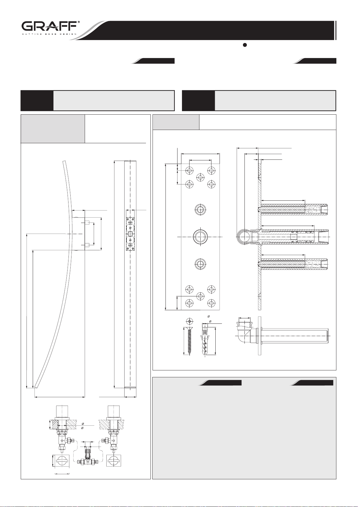
Spout Connection Rough Set
Conjunto de Conexión del Caño
2-3/4" (70mm)
1-37/64" (40mm)
Dear Customer Estimado Cliente
Thank you for selecting our product. We are confident we can fully satisfy
your expectations by offering you a wide range of technologically advanced
products which directly result from our many years of experience in faucet
and fitting production.
For care, use soft towel with soap and water
ATTENTION! ATENCIÓN!
6000-C14-**-T
only! Under no circumstances should you use
any chemicals.
LUNA Lavatory Faucet
with Wall-Mount Spout
El Grifo del Lavabo
con caño Montado
en la Pared LUNA
2-1/4" (57mm)
~1-17/32" (~39mm)
63/64" (25mm)
3/16" (5mm)
3-5/32" (80mm)
3-53/64" (97mm)
~26-3/4" (~ 682mm)
~23-7/8" (~ 609mm)
~8-25/32" (~ 223mm)
(38mm)
MAX. 1-1/2"
1-57/64"
2-23/64" (60mm)
(48mm)
2x 1-1/2"
(2x 38mm)
1/2"NPT
3-7/8"(99mm)
5-11/16" (144mm)
2-3/64" (52mm)
5/16"
HEX KEY
~39-9/16" (~1005mm)
10-15/32" (266mm)
63/64"
(25mm)
1-31/32" (50mm)
Tools and Materials
Tape Measure
•
Pencil
•
Drill
•
Blade Screwdriver
•
Philips Screwdriver
•
Hex Wrenches
•
Level
•
Silicone Sealant
•
25/64"
( 10mm)
1-31/32" (50mm)
3-5/32" (80mm)
1/2-14NPT
Herramientas y materiales
Cinta para media
•
Lápiz
•
Taladro
•
Destornillador plano
•
Destornillador de punta
•
de cruz o Phillips
Llave hexagonales
•
Nivel
•
Sellador de silicona
•
ESPAÑOLENGLISH
1
Rev. 2 October 2010
Page 2
LAVATORY FAUCET (with Wall-Mount Spout)
EL GRIFO DEL LAVABO (con Caño Montado en la Pared)
Installation Instructions Instrucciones de instalación
6000-C14-**-T
A
2
5
Make sure that the
®
Teflon
insert is in
a proper position
in the spout holder.
Asegúrese que el
insertador de Teflon
se encuentren en
su lugar en el parte
de montaje del caño.
®
LUNA Lavatory Faucet • El Grifo del Lavabo LUNA
4
3
6
7
8
3
4
1
9
10
11B
1/2NPT
19
18
17
6
7
8
9
10
11A
12
13
14
15
16
12
13
14
1/4 TURN
1/4 DE VUELTA
COUNTERCLOCKWISE OPENING
SE ABRE HACIA LA IZQUIERDA
1-57/64" (48mm)
1-57/64" (48mm)
2-23/64" (60mm)
OFF
ON ON
15
1/4 TURN
1/4 DE VUELTA
CLOCKWISE OPENING
SE ABRE HACIA LA DERECHA
1-57/64" (48mm)
1-57/64" (48mm)
2-23/64" (60mm)
OFF
IOG 2294.00
1
2
Rev. 2 October 2010
Page 3
LAVATORY FAUCET (with Wall-Mount Spout)
EL GRIFO DEL LAVABO (con Caño Montado en la Pared)
Installation Instructions Instrucciones de instalación
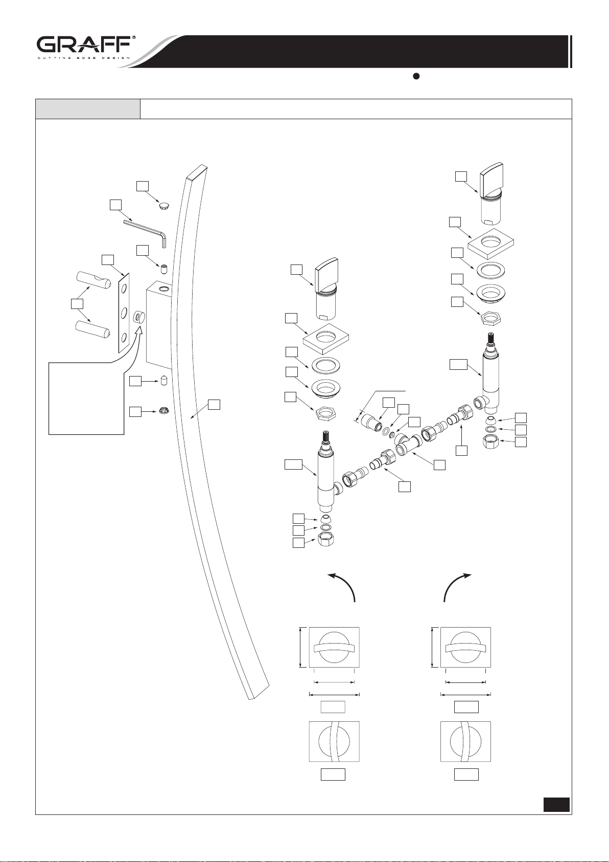
1 WALL-MOUNT SPOUT CAÑO MONTADO EN LA PARED
2 WASHER ARANDELA
3 FIXING SCREW (2 PCS.) TORNILLO DE FIJACIÓN (2 PIEZAS)
4 CAP (2 PCS.) TAPÓN (2 PIEZAS)
5 MOUNTING SLEEVE (2 PCS.) CASQUILLO DE MONTAJE (2 PIEZAS)
6 HANDLE ASSEMBLY (2 PCS.) JUEGO DE LA MANILLA (2 PIEZAS)
7 HANDLE BASE (2 PCS.) BASE DE LA MANILLA (2 PIEZAS)
8 WASHER (2 PCS.) ARANDELA (2 PIEZAS)
9 FLANGED NUT (2 PCS.) TUERCA CON BRIDA (2 PIEZAS)
10 COUNTER NUT (2 PCS.) TUERCA DE CONTRA (2 PIEZAS)
11A RIGHT VALVE (with clockwise opening cartridge) VÁLVULA DERECHA (con cartucho que se abre hacia la derecha)
11B LEFT VALVE (with counterclockwise opening cartridge) VÁLVULA IZQUIERDA (con cartucho que se abre hacia la izquierda)
12 CONE GASKET (2 PCS.) JUNTA CÓNICA (2 PIEZAS)
13 WASHER (2 PCS.) ARANDELA (2 PIEZAS)
14 COUPLING NUT (2 PCS.) TUERCA DE FIJACIÓN (2 PIEZAS)
15 HOSE, 11-13/16” (300mm) length, (2 PCS.) MANGUERA, longitud 11-13/16” (300mm), (2 PIEZAS)
16 T-CONNECTION CONEXIÓN „T”
17 NOZZLE INYECTOR
18 O-RING SEAL JUNTA O-RING
19 NIPPLE PIEZA DE EMPALME
A HEX KEY LLAVE HEXAGONAL
1070
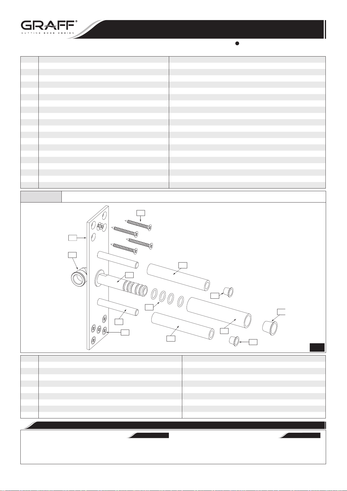
Spout Connection Rough Set • Conjunto de conexión del caño
R9
R
R1
R7
R2
R8
R4
R6
R3
R9
R7
R COMPLETE SPOUT CONNECTION ROUGH CONJUNTO COMPLETO DE CONEXIÓN DEL CAÑO
R1 SUPPLY ELBOW 1/2”NPT CODO 1/2”NPT DE SUMINISTRO
R2 SPOUT CONNECTION CONEXIÓN DEL CAŃO
R3 MOUNTING PIN (2 PCS.) PERNO DE MONTAJE (2 PIEZAS)
R4 O-RING SEAL (4 PCS.) JUNTA O-RING (4 PIEZAS)
R5 SPOUT CONNECTION PROTECTION CONECTOR DEL CAŃO DE PROTECCIÓN
R6 PROTECTION CAP TAPÓN DE PROTECCIÓN
R7 PROTECTION SLEEVE (2 PCS.) CASQUILLO DE PROTECCIÓN (2 PIEZAS)
R8 PROTECTION CAP (2 PCS.) TAPÓN DE PROTECCIÓN (2 PIEZAS)
R9 SCREW WITH ANCHOR (10 PCS) TORNILLO CON ESTACA (10 PIEZAS)
R5
R8
2
Carefully unpack and inspect all the components for damage. To protect against damage, return all components
to the carton until ready to install.
IOG 2294.00
PRODUCT INSPECTION
Desembale con cuidado y cerciórese de que ningún com
ponente esté dañado. Para protección contra daños, vuelva
a colocar todos los componentes en la caja de embalaje hasta
el momento de su instalación.
3
INSPECCIÓN DEL PRODUCTO
•
ESPAÑOLENGLISH
Rev. 2 October 2010
-
Page 4
LAVATORY FAUCET (with Wall-Mount Spout)
EL GRIFO DEL LAVABO (con Caño Montado en la Pared)
Installation Instructions Instrucciones de instalación
NOTE: Make sure the water supply is off before start of installation.
Lavatory wall-mount spout (1) is to be mounted on the wall.
Before starting of spout installation (1) you should plan:
➣ point of assembly of spout connection rough
from a spout should be at the height guaranteeing a comfortable use of the lavatory faucet,
➣ the routing of mixed water supply piping to spout (1); it
is recommended to prepare piping with maximum diameter 1/2” with 1/2”NPT male thread connector to connect
the spout connection rough (R), and with female thread
1/2”NPT connector to connect T-connection (16) & nipple
(19) set – see fig. 4.1,
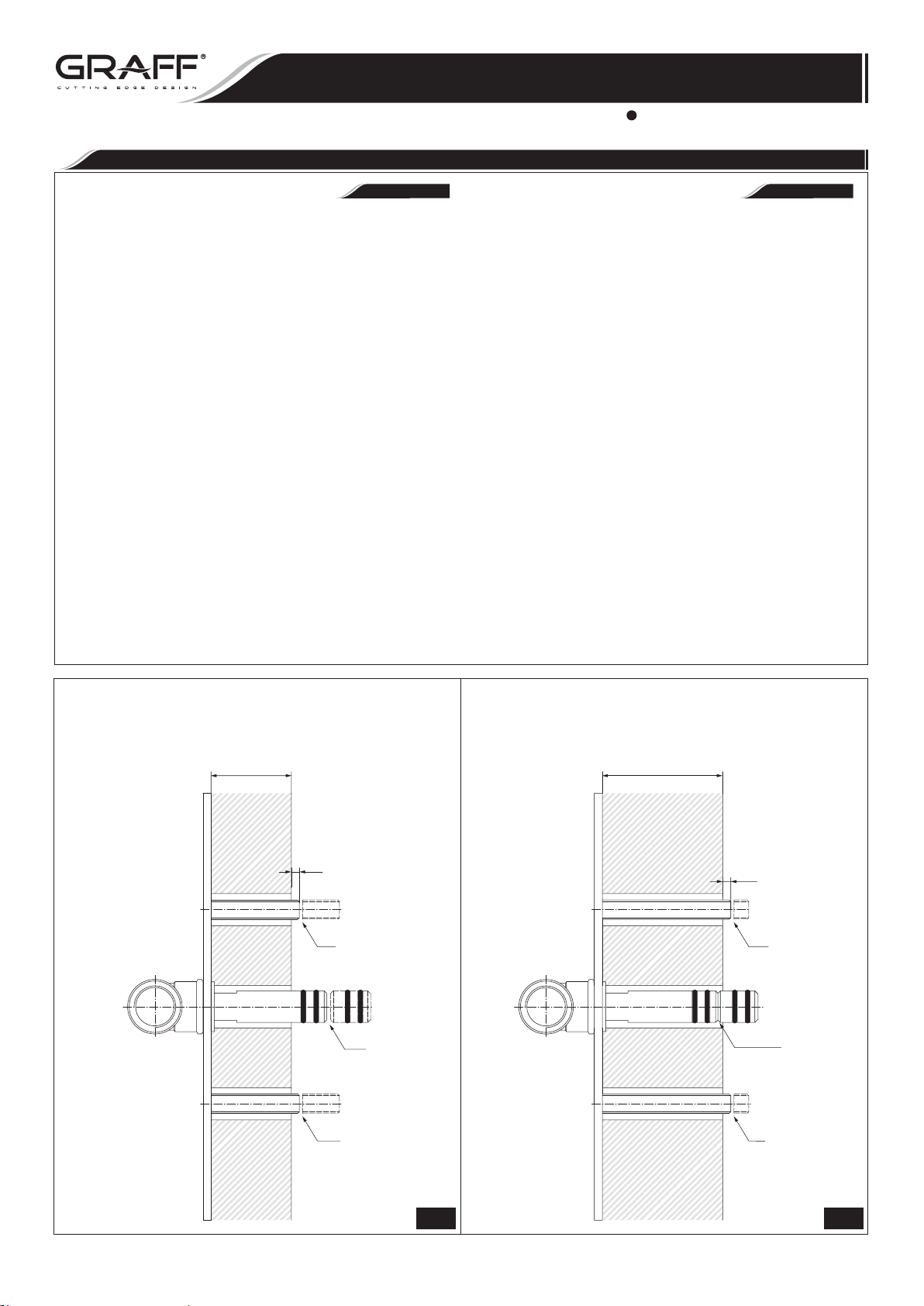
➣ type of wall: standard wall (VERSION 1 - see fig. 3.1) or
marble wall (VERSION 2 - see fig. 3.2).
Before beginning the installation works decide on the type of
wall that it will be used:
VERSION 1 /see fig. 3.1/: Total wall thickness (T):
MIN. 1”- MAX. 2” /standard wall/.
VERSION 2 /see fig. 3.2/: Total wall thickness (T):
MIN. 2”- MAX. 3” /marble wall/.
Position of spout connection rough
in such way that the
range applicable for each version.
(T) value would be in the MIN.-MAX.
(R) should be determined
(R); outflow
SPOUT INSTALLATION
NB: Antes de empezar el montaje asegúrese que el sumini-
stro de agua esté cerrado.
El caño del grifo del lavabo
je en la pared. Antes de iniciar el montaje del caño (1) tiene
que planificar:
➣ lugar del montaje del conjunto de conexión del caño (R),
la posición del flujo saliente del caño debe garantizar el
uso cómodo del grifo del lavabo.
➣ el recurrido de la instalación que lleva el agua mezclada al
caño (1); le recomendamos preparar una instalación de
max diámetro 1⁄2” dotada de una pieza de conexión con
la rosca externa 1⁄2”NPT para unir el conjunto de cone
xión del caño
interna 1⁄2”NPT para acoplar el conjunto que consta del
tubo en T (16) y la pieza de empalme (19) - ver el dis.
4.1.
➣ tipo del muro: la pared standard (VARIANTE 1 - ver el
dis. 3.1) o la pared de mármol (VARIANTE 2 - ver el dis.
3.2)
Antes de proceder a la instalación debe determinar el tipo del
muro:
VARIANTE 1 /ver el dis. 3.1/: Espesor total del muro (T):
MIN. 1” – MAX. 2” /la pared estandard/.
VARIANTE 2 /ver el dis. 3.2/: Espesor total del muro (T):
MIN. 2” – MAX. 3” /la pared de mármol/.
Se debe definir la profundidad de colocación del conjunto de
conexión del caño
en los límites MIN.-MAX. para el variante en cuestión.
(R) y de una pieza de conexión con la rosca
(R) de tal manera que el valor (T) quepa
(1) está destinada para el monta-
MONTAJE DEL CAÑO
•
ESPAÑOLENGLISH
-
VERSION 1 • VARIANTE 1
Standard Wall: MIN.1”-MAX.2”
Pared Estandard: MIN.1”-MAX.2”
WALL MIN. 1"
WALL MAX. 2"
T T
0.2"
CUT
CORTE
CUT
CORTE
CUT
CORTE
VERSION 2 • VARIANTE 2
Marble Wall: MIN.2”-MAX.3”
Pared Marmol: MIN.2”-MAX.3”
WALL MIN. 2"
WALL MAX. 3"
0.2"
CUT
CORTE
DON`T CUT
NO CORTE
CUT
CORTE
IOG 2294.00
3.1 3.2
4
Rev. 2 October 2010
Page 5
LAVATORY FAUCET (with Wall-Mount Spout)
EL GRIFO DEL LAVABO (con Caño Montado en la Pared)
Installation Instructions Instrucciones de instalación
R
R7&R8
R7&R8
R5&R6
5
Finished Wall
R2
Acabado de la pared
5
Make sure that the Teflon® insert
is in a proper position in the spout holder.
Asegúrese que el insertador de Teflon
se encuentren en su lugar en el parte
de montaje del caño.
~1-21/32"(42mm)
4
A
3
2
1
3
®
4
19
15
16
15
4.1
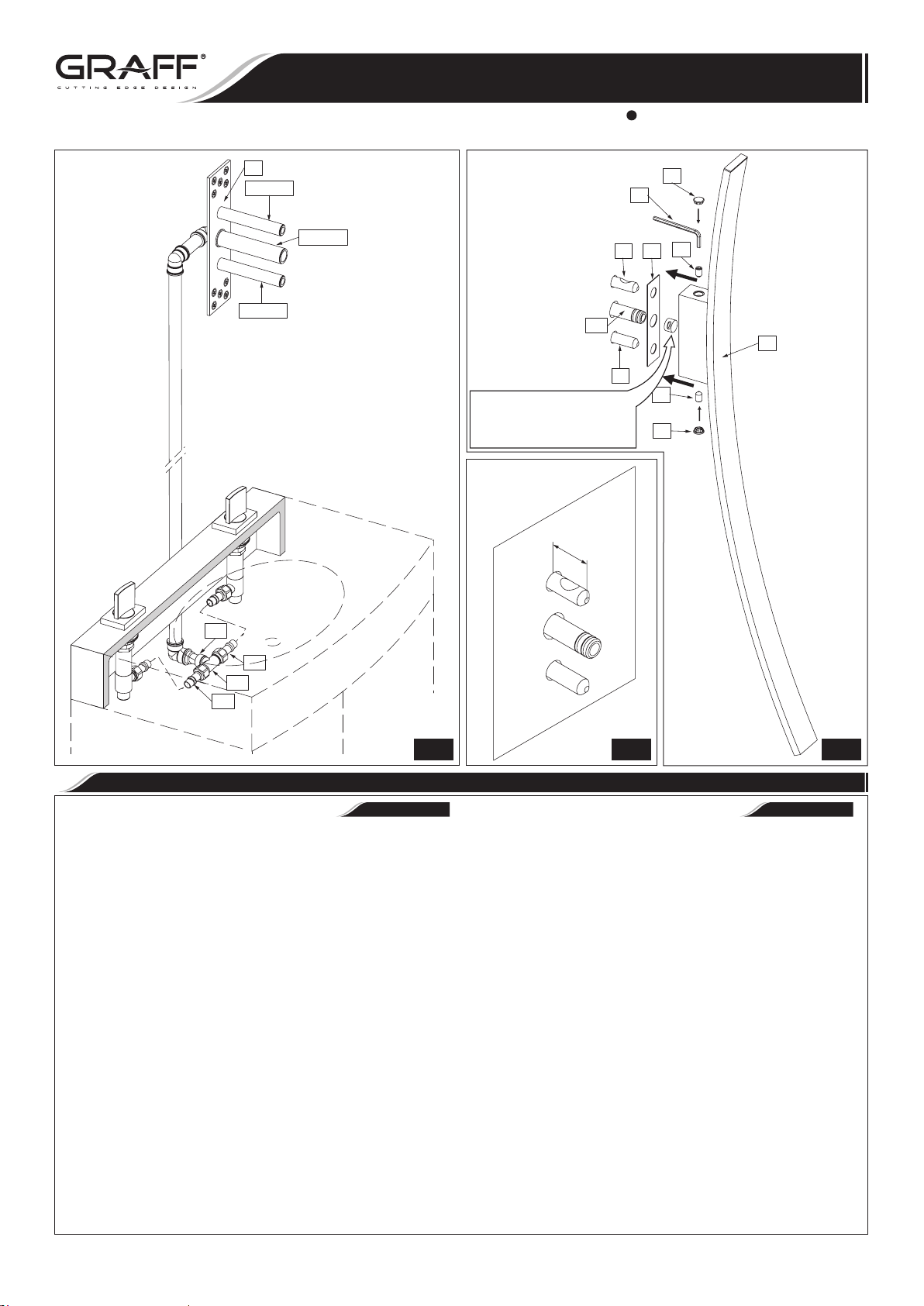
1. Connect the spout connection rough (R) to mounting cavity in the wall using mounting screws
Note: Position spout connection rough (R) correctly in
vertical and horizontal axis using level.
2. Connect water supply piping to supply elbow with a female
thread 1/2”NPT (R1) - see fig. 4.1.
3. Make sure, that all protection sleeves (R5 & R7) are in
correct position on spout connection rough
with construction work on finished wall layer.
4. After finishing the construction work, remove the protec
tion sleeves (R5 & R7) together with protection caps
& R8) from spout rough
the type of wall, that you have, choose the appropriate
version of further steps:
VERSION 1 /see fig. 3.1/: Total wall thickness
1”- MAX. 2” /standard wall/
➣ cut the mounting pins
two pins protrude from the finished wall by about 0.2”;
remove all burrs after cutting,
➣ cut spout connection
nufacturing groove is; remove all burrs after cutting, do
not damage o-ring seals (R4).
(R) – see fig. 4.1. Depending on
(R3) using hack-saw so that the
(R2) at the place where the ma-
(R9).
(R). Continue
(R6
(T): MIN.
4.2 4.3
SPOUT INSTALLATION
1. Sujete el conjunto de conexión del caño
nillos de fijación
Atención: Posicione bien vertical y horizontalmente el
conjunto de conexión del caño
burbuja.
2. Conecte al codo de suministro con rosca externa 1⁄2”NPT
(R1) la instalación que lleva el agua al caño – ver el dis.
4.1.
3. Asegúrese que todos los casquillos de protección (R5 &
-
R7) se encuentren en su lugar en el cojunto de conexión
(R). Ahora puede proceder a realizar la superficie de aca-
bado de la pared.
4. Cuando termine las obras de acabado, quite los casquillos
de protección (R5 & R7) con los tapones de protección
(R6 & R8) del conjunto de conexión (R) - ver el dis. 4.1.
En función del tipo de la pared en su caso escoja el varian
te adecuado para continuar el montaje:
VARIANTE 1 /ver el dis. 3.1/: Espesor total del muro
(T): MIN. 1” – MAX 2” /la pared estandard/
➣ corte los pernos de montaje (R3) con el serrucho para
metal de tal modo que los pernos emerjan de la cara
interior de la pared de acabado de unos 0,2”; elimine
todas las rebabas que se puedan producir en el mo
mento de cortar,
➣ corte la conexión del caño
nota la ranura marcada por la fábrica; elimine todas
las rebabas que se puedan producir en el momento de
cortar, no dañe las junta o-ring
(R9) en el vano de montaje en la pared.
INSTALACION DEL CAÑO
•
ESPAÑOLENGLISH
(R) con los tor-
(R) con ayuda del nivel de
(R2) en el lugar donde se
(R4).
-
-
IOG 2294.00
5
Rev. 2 October 2010
Page 6
LAVATORY FAUCET (with Wall-Mount Spout)
EL GRIFO DEL LAVABO (con Caño Montado en la Pared)
Installation Instructions Instrucciones de instalación
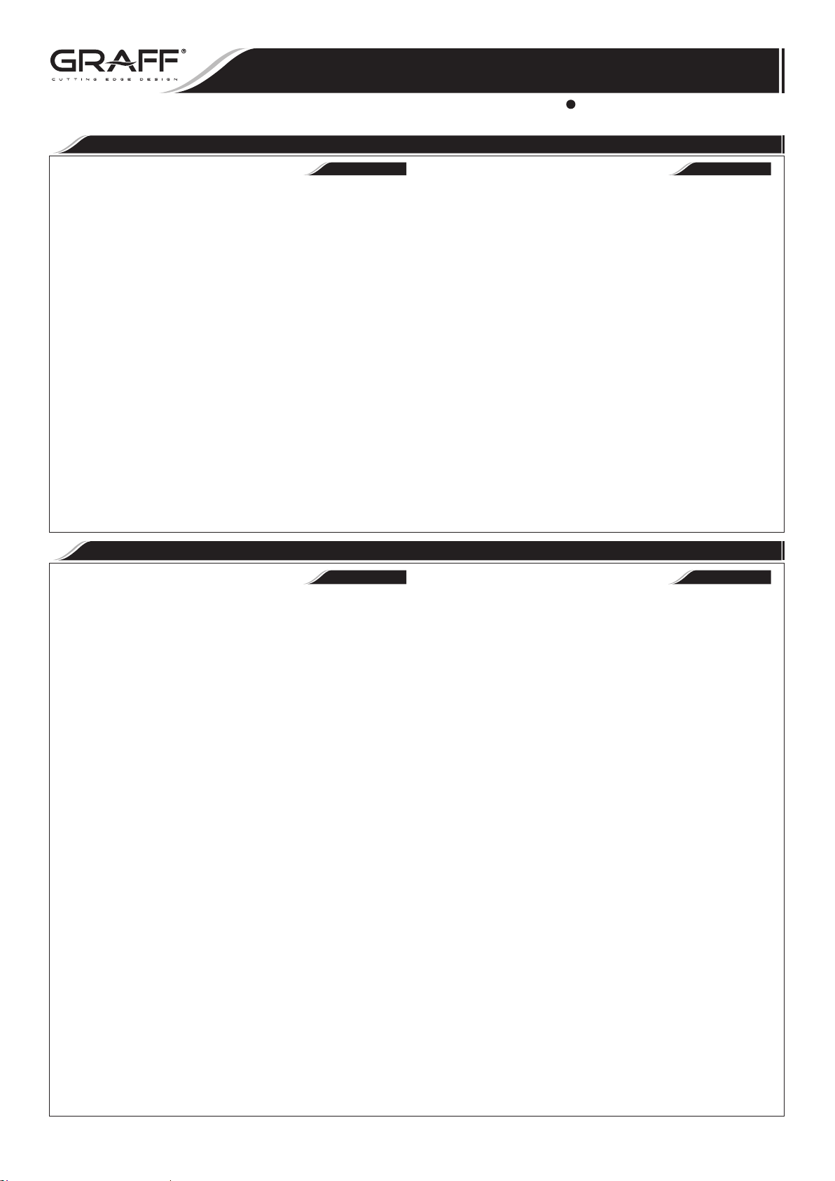
VERSION 2 /see fig. 3.2/: Total wall thickness (T): MIN.
2”- MAX. 3” /marble wall/
➣
cut the mounting pins (R3) using hack-saw so that the
two pins protrude from the finished wall by about 0.2”;
remove all burrs after cutting,
➣
ATTENTION! Do not cut spout connection (R2).
5. Screw mounting sleeves
sistance is felt /see fig. 4.3/. ATTENTION! The distance
from the finished wall to the tip of sleeve (5) should
be about 1-21/32” (42mm) /see fig. 4.2/. Top sleeve
(5) should be positioned in such way that the tapered
recess is pointing upwards, and the bottom sleeve
should be positioned in such way that the tapered recess
is pointing downwards /see fig. 4.2/.
6. Put the washer
7. Screw the fixing screws
sockets in spout holder /see fig. 4.3/. Use the hex key
8. Slide the spout
spout connection
is correctly positioned.
9. Holding the spout
screws (3) using the hex key (A).
10. Put in the masking caps
(2) onto the mounting sleeves (5).
(1) over two mounting sleeves (5) and
(R2), pay attention that the washer (2)
(5) onto the pins (R3) until re-
(5)
(3) 1-1.5 turns into appropriate
(A).
(1) screw all the way in both of fixing
(4) into spout holder.
HANDLES INSTALLATION
SPOUT INSTALLATION
VARIANTE 2 /ver el dis. 3.2/: Espesor total del muro (T):
MIN. 2” – MAX. 3” /la pared de mármol/
➣ corte los pernos de montaje (R3) con el serrucho para me-
tal de tal modo que los pernos emerjan de la cara interior
de la pared de acabado de unos 0,2”; elimine todas las
rebabas que se puedan producir en el momento de cortar,
➣ ATENCIÓN: No corte la conexión del caño (R2).
5. Sobre los pernos de montaje (R3) enrosque los casquillos de
montaje (5) girándolos a tope /ver el dis. 4.3/. ATENCIÓN:
La distancia entre la parte frontal de la pared de acabado y la parte frontal del casquillo (5) debe de ser de
unos 1-21/32” (42 mm) /ver el dis. 4.2/. Ponga el casquillo
superior (5) de tal manera que el recorte cónico esté dirijido
hacia arriba, mientras el casquillo inferior (5) ponga de tal
manera que el recorte esté dirijido hacia abajo /ver el dis.
4.2/.
6. Sobre los casquillos de montaje (5) enroscados ponga la aran-
dela (2).
7. Apriete de un 1-1,5 giro los tornillos de fijación (3) en los
asientos adecuados en la parte de montaje del caño /ver el dis.
4.3/. Use la llave alien (A).
8. Coloque el caño (1) sobre dos casquillos de montaje (5) y la
conexión del caño (R2). Preste atención a posicionar correctamente la arandela (2).
9. Sosteniendo el caño (1) apriete a tope ambos tornillos de fija
ción (3) con la llave alien (A).
10. Ponga los tapones (4).
INSTALACIÓN DE LAS MANILLAS
•
INSTALACION DEL CAÑO
•
ESPAÑOLENGLISH
-
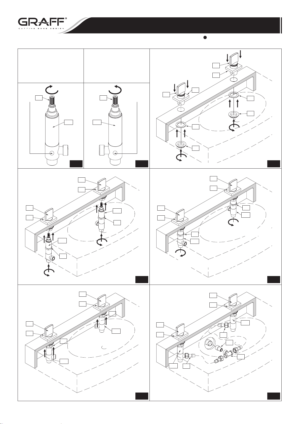
See fig. 5.1-5.2, 6.1-6.5
1) Place handle base (7) and center over side hole of mount-
ing surface - see fig. 1 and 6.1.
2) Insert handle assembly (6) into the hole of a handle base
(7) and a deck. From underneath the lavatory place the
washer (8) and then screw the flanged nut (9) (fig.6.1).
3) Set the handle as on fig. 1 - “OFF” position.
4) Turn the spline of a cartridge in a valve (11A) & (11B) to
OFF position:
➣ in the hot water valve (fig. 5.1): left valve marked with
the red sticker turn the cartridge spline (A) in clockwise direction,
➣ in the cold water valve (fig. 5.2): right valve marked
with the blue sticker turn the cartridge spline (B) in
counterclockwise direction.
5) Turn onto the valve (11A) & (11B) counter nut (10) (fig.
6.2).
6) Holding the valve with the outlet pointing towards you (in
case of hot water valve) (11B)/ or outwards (in case of
cold water valve (11A)) put the valve into the handle assembly (6), so the spline of the cartridge mates with the
spline of the handle (fig. 6.2).
7) Thread in the valve home, then release the valve 0.5 to
1.5 turn. Position the handle (6) as on fig. 1. Tighten lightly the counter nut (10) on the valve (fig. 6.3).
8) Note the position of the outlet of the valve and make sure
it fits the flexible hose connection (15) - see fig. 6.5. If
it is ok tighten the counter nut (10) - see fig. 6.4, if not
move the valve by the required angle. To achieve this do
the following:
➣ unscrew the valve without disconnecting the handle,
➣ hold the handle,
➣ disconnect the valve from the handle,
➣ rotate the valve by required angle,
➣ connect the valve to the handle as described above,
➣ secure the handle and the valve with the counter
nut (10).
Ver dis. 5.1-5.2, 6.1-6.5
1) Coloque la base de la manilla (7) y centre en el agujero
lateral de la superficie de montaje - ver dis. 1 y 6.1.
2) Poner el juego de manilla (6) al agujero de la base de la
manilla (7) y de la superficie de montaje. Colocar la arandela por debajo del lavabo (8) y atornillar la tuerca con
brida (9) (dis. 6.1).
3) Poner la manilla como en el dib. 1 en la posición “OFF”.
4) Poner la polichaveta del cartucho en la válvula (11A) y
(11B) en la posición “cartucho cerrado” - “OFF”:
➣ en el caso de la válvula de agua caliente (dis. 5.1): la
válvula izquierda con etiqueta roja con cartucho cerrado a la derecha - girar la polichaveta del cartucho (A)
a la derecha,
➣ en el caso de la válvula de agua fría (dis. 5.2) válvula
derecha con etiqueta azul con cartucho cerrado a la
izquierda - girar la polichaveta del cartucho (B) a la
izquierda.
5) Atornillar en la válvula (11A) y (11B) la tuerca de contra
(10) (dis. 6.2).
6) Teniendo la válvula con su salida hacia sí (en el caso
de la válvula de agua caliente, (11B)/ hacia fuera
(en el caso de la válvula de agua fría (11A)), ponerla a la manilla (6), la polichaveta del cartucho se engranará con la polichaveta de la manilla (dis. 6.2).
7) Enroscar la válvula a su máximo y después retirar la válvula a 0.5 hacia 1.5 de la rotación. Poner la manilla (6) como
en el dib. 1. Apretar ligeramente la tuerca de contra (10)
en la válvula (dis. 6.3).
8) Recordar la posición del escape de la válvula y estimar si
concuerda con la manguera flexible (15) - ver el dis. 6.5.
Si concuerda, atornillar la tuerca de contra (10) - ver el
dis. 6.4., si no concuerda; reponer la válvula teniendo en
cuenta el ángulo adecuado. Para hacer eso:
➣ destornillar la válvula sin desconectarla con la manilla,
➣ sujetar la manilla,
➣ desconectar la válvula de la manilla,
➣ reponer la válvula hacia su ángulo adecuado,
➣ conectar la válvula con la manilla teniendo en cuenta lo
susodicho,
➣
proteger la manilla y la válvula con la tuerca de contra (10)
ESPAÑOLENGLISH
.
IOG 2294.00
6
Rev. 2 October 2010
Page 7
LAVATORY FAUCET (with Wall-Mount Spout)
EL GRIFO DEL LAVABO (con Caño Montado en la Pared)
Installation Instructions Instrucciones de instalación
Turn spline of cartridge (A)
to (OFF) position max.
clockwise direction.
Luego girar la polichaveta
de cartucho (A)
en la posición (OFF) maximo
hacia la derecha.
A
11B 11A
Hot water valve
is marked with red sticker
La válvula de agua caliente
esta marcada con le etiqueta roja
5.1 5.2
Turn spline of cartridge (B)
to (OFF) position max.
counterclockwise direction.
Luego girar la polichaveta
de cartucho (B)
en la posición (OFF) maximo
hacia la ízquierda.
B
6
7
6
7
7
6
8
9
8
Cold water valve
is marked with blue sticker
La válvula de agua fría
esta marcada con le etiqueta azul
9
6.1
6
7
6
11A
7
6
7
10
11A
10
1-1.5 turn clockwise direction
1-1.5 girar hacia la derecha
11B
10
11B
10
1-1.5 turn counterclockwise direction
1-1.5 girar hacia la ízquierda
6.2 6.3
6
7
10
6
7
11A
6
7
10
6
7
11A
15
19
IOG 2294.00
11B
16
11B
15
6.4 6.5
7
Rev. 2 October 2010
Page 8
LAVATORY FAUCET (with Wall-Mount Spout)
EL GRIFO DEL LAVABO (con Caño Montado en la Pared)
Installation Instructions Instrucciones de instalación
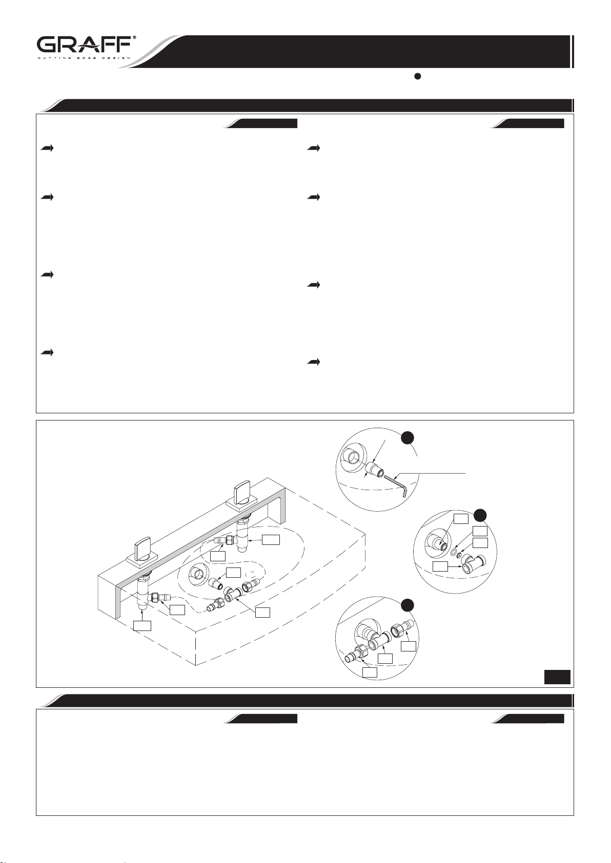
MAKE CONNECTION TO WATER LINES
See fig. 1 & 7
Use mounting set to 3/8” copper tubes consisting of cone
gaskets (12), metal washers (13) and coupling nuts (14).
Pay attention that the hot and cold water is correctly connected. It is recommended to mount ball valves with a filter on the water supply.
Screw a nipple (19) into the ferrule of the system supplying water to the spout connection rough (R). Use a 5/16”
hex key. The ferrule of the system supplying water to the
spout connection rough (R) should be equipped with a wa-
ter supply pipe with a 1/2”NPT female thread placed in
the wall at such a height that it is possible to correctly
connect the valves (11A) and (11B) with the installed
T-connection (16) using the hoses (15).
Put the nozzle (17) and then the o-ring (18) into the
T-connection ferrule (16) as shown in fig. 7. You can grease
slightly the nozzle (17) and o-ring seal (18) with silicone,
so they would be kept in place in the socket of the T-connection (16) during threading of the T-connection (16)
onto nipple (19). Screw the T-connection (16) onto the
nipple (19). Avoid using too much force while tightening
the connection.
Connect one end of the hoses (15) to the lateral outputs of
the valves (11A) and (11B) and the other to the installed
T-connection
Use adjustable wrench when tightening. Do not overtighten.
(16).
CONEXIÓN A LAS FUENTES DE AGUA
•
Ver dis. 1 y 7
Use un completo de montaje para tuberias de CU de 3/8”
que consisten en empaquetaduras (12), las arandelas de
metal (13) y uniones (14). Tenga en cuenta la conexión
correcta del agua fría y caliente. Es recomendable montar
válvulas de bola con filtro en la alimentación.
Al tubo corto de la instalación que suministra el agua al
conjunto de conexión cruda del caño (R) atornille el racor
(19). Para ello use la llave hexagonal 5/16”. El tubo corto de la instalación que alimenta el conjunto de conexión
cruda del caño (R) debería poseer una tubuladura con la
rosca interior de 1/2”NPT situada en la pared a la altura
que facilite la conexión correcta a través de las mangueras
(15) con las válvulas (11A) y (11B) con el tubo en T
(16) instalado.
En el tubo corto central del tubo en T (16) meta la tobera
(17) así como está presentado en el dib. 7, luego meta la
junta o-ring (18). Puede poner un poco de silicona sobre
el inyector (17) y la junta o-ring (18) para impedir el
traslado de estos elementos en el asiento del tubo en T en
el momento de enroscar el tubo en T (16) sobre la pieza
de empalme (19). Atornille el tubo en T (16) en el racor
(19). No lo haga forzando al apretar.
Una las mangueras (15) por un lado a las salidas laterales
de las válvulas (11A) y (11B), y por el otro al tubo en T
instalado (16).
Utilice llaves ajustables cunado necesite ajustar alguna pieza.
No ajuste demasiado.
ESPAÑOLENGLISH
11A
15
19
15
16
11B
OPERATING INSTRUCTION
Levers are used to open and regulate the water flow. Full flow
is obtained by turning the lever through 900 (the cold water
tap on the right goes clockwise, the hot water tap on the left
counterclockwise). The intensity of the water flow is regulated
by positions between 00-900.
1
1/2" NPT
5/16" HEX KEY
LLAVE HEXAGONAL 5/16"
19
16
2
18
17
3
15
16
15
LA DESCRIPCIÓN DEL FUNCIONAMIENTO
•
ESPAÑOLENGLISH
Para abrir la salida y la regulación del flujo del agua sirven las
palancas. La apertura total sucede al tornar la palanca por
el ángulo de 900 (de acuerdo con el movimiento de las manillas del reloj en caso de la palanca del agua fría colocada en
el lado derecho, en contrario del movimiento de las manillas
del reloj en caso de la palanca del agua caliente colocada en
el lado izquierdo). La regulación de la intensidad del flujo de
agua sucede en las posiciones 0
0
-900.
7
IOG 2294.00
8
Rev. 2 October 2010
Page 9
LAVATORY FAUCET (with Wall-Mount Spout)
EL GRIFO DEL LAVABO (con Caño Montado en la Pared)
Installation Instructions Instrucciones de instalación
CARE AND MAINTENANCE / WARRANTY
Your Graff valve is designed and engineered in accordance
with the highest quality and performance standards.Be sure
not to damage the finish during installation. Care should be
given to the cleaning of this product. Although its finish is
extremely durable, it can be damaged by harsh abrasives or
polish. Never use abrasive cleaners, acids, solvents, etc. to
clean any Graff product. To clean, simply wipe gently with a
damp cloth and blot dry with a soft towel.
Warranty conditions and warranty registration card are outlined on a separate sheet.
HOTLINE FOR HELP
NUMERO DE EMERGENCIA
For toll-free information and answers to your
questions, call:
Llame sin costo para obteiner informacion
y respestas a sus preguntas:
CUIDADO Y MANTENIMIENTO / GARANTÍA
•
ESPAÑOLENGLISH
Su válvula de la
los estándares de funcionamiento y calidad más altos. Este
seguro no dañar las terminaciones del grifo durante la instalación. Cuide el producto manteniendolo siempre limpio.
Aunque su acabado es extremadamente durable, puede ser
dañado por los abrasivos o pulientes ásperos. Nunca utilice
limpiadores abrasivos, ácidos, solventes, el etc. para limpiar
cualquier producto de la Graff. Para limpiar, simplemente use
un paño húmedo y seque con una toalla suave.
Las condiciones de la garantía y la tarjeta del registro de la
garantía se encuentran en una pagina separada.
Graff esta diseñado y dirigido acuerdo con
1 - 800 - 954 - GRAF (4723)
www.graffcollection.com
IOG 2294.00
All dimensions and drawings are for reference only. For details, please refer to actual products.
Todas las dimensiones y dibujos sirven únicamente de referencia. Para consultar detalles, ver los productos.
9
Rev. 2 October 2010
 Loading...