


*MEC96
UPFLOW / HORIZONTAL TWO-STAGE
GAS FURNACE
(Type FSP CATEGORY IV Direct or Non Direct Vent Air Furnace)
These furnaces comply with requirements embodied in the American National Standard / National Standard of Canada ANSI Z21.47·CSA-2.3 Gas Fired Central Furnaces.
Installer: Affix all manuals
adjacent to the unit.
As a professional installer you have an obligation to know the product better than the customer. This includes all safety precautions and related items.
Prior to actual installation, thoroughly familiarize yourself with this Instruction Manual. Pay special attention to all safety warnings. Often during installation or repair it is possible to place yourself in a position which is more hazardous than when the unit is in operation.
Remember, it is your responsibility to install the product safely and to know it well enough to be able to instruct a customer in its safe use.
Safety is a matter of common sense...a matter of thinking before acting. Most dealers have a list of specific good safety practices...follow them.
The precautions listed in this Installation Manual are intended as supplemental to existing practices. However, if there is a direct conflict between existing practices and the content of this manual, the precautions listed here take precedence.
 RECOGNIZE THIS SYMBOL
AS A SAFETY PRECAUTION.
TABLE OF CONTENTS |
|
SAFETY CONSIDERATIONS .................................... |
2 |
SHIPPING INSPECTION ............................................ |
4 |
ELECTROSTATIC DISCHARGE (ESD) PRECAUTIONS ................... |
4 |
TO THE INSTALLER .............................................. |
5 |
PRODUCT DESCRIPTION ......................................... |
5 |
FEATURES ....................................................... |
5 |
PRODUCT APPLICATION ......................................... |
5 |
LOCATION REQUIREMENTS & CONSIDERATIONS ........... |
6 |
CLEARANCES AND ACCESSIBILITY ................................... |
7 |
EXISTING FURNACE REMOVAL ..................................... |
8 |
THERMOSTAT LOCATION .......................................... |
8 |
COMBUSTION & VENTILATION AIR REQUIREMENTS .................. |
9 |
INSTALLATION POSITIONS ...................................... |
9 |
HORIZONTAL APPLICATIONS & CONSIDERATIONS ..................... |
9 |
FURNACE SUSPENSION .......................................... |
10 |
FRONT COVER PRESSURE SWITCH TUBE LOCATION ................ |
10 |
DRAIN TRAP AND LINES ......................................... |
10 |
HORIZONTAL FURNACE LEVELING ................................ |
10 |
ALTERNATE ELECTRICAL AND GAS LINE CONNECTIONS ............. |
10 |
DRAIN PAN .................................................... |
10 |
FREEZE PROTECTION ............................................ |
10 |
PROPANE GAS/HIGH ALTITUDE INSTALLATIONS .......... |
10 |
VENT/FLUE PIPE & COMBUSTION AIR PIPE ................. |
11 |
DUAL CERTIFICATION: NON-DIRECT/DIRECT VENT ................ |
11 |
MATERIALS AND JOINING METHODS .............................. |
11 |
PROPER VENT/FLUE AND COMBUSTION AIR PIPING PRACTICES ..... |
12 |
TERMINATION LOCATIONS ........................................ |
12 |
CANADIAN VENTING REQUIREMENTS .............................. |
13 |
STANDARD FURNACE CONNECTIONS .............................. |
13 |
VENT/FLUE PIPE .............................................. |
13 |
NON-DIRECT VENT (SINGLE PIPE) PIPING ........................ |
15 |
VENT/INTAKE TERMINATIONS FOR INSTALLATION |
|
OF MULTIPLE DIRECT VENT FURNACES ........................ |
18 |
CONCENTRIC VENT TERMINATION ................................. |
18 |
SIDE WALL VENT KIT .......................................... |
18 |
CONDENSATE DRAIN LINES & DRAIN TRAP ................. |
18 |
GENERAL DRAIN INFORMATION ................................... |
18 |
FIELD SUPPLIED DRAIN ......................................... |
19 |
UPFLOW MODEL INSTALLED VERTICALLY .......................... |
19 |
DRAIN EXITING RIGHT SIDE ..................................... |
19 |
DRAIN EXITING LEFT SIDE ...................................... |
20 |
UPFLOW MODEL INSTALLED HORIZONTALLY |
|
WITH RIGHT SIDE DOWN ..................................... |
20 |
UPFLOW MODEL INSTALLED HORIZONTALLY |
|
WITH LEFT SIDE DOWN ...................................... |
20 |
*NOTE: Please contact your distributor or our website for the applicable Specification Sheet referred to in this manual.
|
5151 San Felipe Suite 500 |
|
Houston, TX 77056 |
IOG-2011F |
www.goodmanmfg.com • www.amana-hac.com |
04/2016 |
© 2014 - 2016 Goodman Manufacturing Company, L.P. |
 is a registered trademark of Maytag Corporation or its related companies and is used under license. All rights reserved.
ELECTRICAL CONNECTIONS ................................... |
21 |
WIRING HARNESS ............................................... |
21 |
115 VOLT LINE CONNECTIONS .................................. |
21 |
JUNCTION BOX RELOCATION ..................................... |
21 |
24 VOLT THERMOSTAT WIRING .................................. |
22 |
SINGLE-STAGE HEATING THERMOSTAT APPLICATION ................ |
23 |
FOSSIL FUEL APPLICATIONS ...................................... |
23 |
TWINNING ..................................................... |
23 |
115 VOLT LINE CONNECTION OF ACCESSORIES |
|
(HUMIDIFIER AND ELECTRONIC AIR CLEANER) .................. |
23 |
GAS SUPPLY AND PIPING ....................................... |
24 |
HIGH ALTITUDE DERATE ......................................... |
24 |
PROPANE GAS CONVERSION ..................................... |
24 |
GAS PIPING CONNECTIONS ...................................... |
25 |
PROPANE GAS TANKS AND PIPING ................................ |
26 |
CIRCULATING AIR & FILTERS .................................. |
27 |
DUCT WORK - AIR FLOW ....................................... |
27 |
CHECKING DUCT STATIC ......................................... |
27 |
BOTTOM RETURN AIR OPENING [UPFLOW MODELS] .............. |
28 |
FILTERS - READ THIS SECTION BEFORE INSTALLING |
|
THE RETURN AIR DUCT WORK ................................ |
28 |
UPRIGHT INSTALLATIONS ......................................... |
29 |
HORIZONTAL INSTALLATIONS ...................................... |
30 |
STARTUP PROCEDURE & ADJUSTMENT ...................... |
30 |
DRAIN TRAP PRIMING ........................................... |
30 |
FURNACE OPERATION ........................................... |
30 |
GAS SUPPLY PRESSURE MEASUREMENT ........................... |
31 |
GAS MANIFOLD PRESSURE MEASUREMENT AND ADJUSTMENT ....... |
32 |
GAS INPUT RATE MEASUREMENT (NATURAL GAS ONLY) ........... |
32 |
TEMPERATURE RISE ............................................. |
33 |
CIRCULATOR BLOWER SPEEDS ................................... |
33 |
DIP SWITCH SETTINGS ......................................... |
34 |
BLOWER HEAT OFF DELAY TIMINGS ............................. |
40 |
NORMAL SEQUENCE OF OPERATION ......................... |
40 |
POWER UP .................................................... |
40 |
HEATING MODE ................................................ |
40 |
COOLING MODE ................................................ |
41 |
FAN ONLY MODE .............................................. |
41 |
OPERATIONAL CHECKS ......................................... |
41 |
SAFETY CIRCUIT DESCRIPTION ............................... |
41 |
INTEGRATED CONTROL MODULE ................................. |
41 |
PRIMARY LIMIT ................................................. |
41 |
AUXILIARY LIMIT ................................................ |
41 |
ROLLOUT LIMIT ................................................ |
42 |
PRESSURE SWITCHES ............................................ |
42 |
FLAME SENSOR ................................................ |
42 |
TROUBLESHOOTING ............................................. |
42 |
ELECTROSTATIC DISCHARGE (ESD) PRECAUTIONS .................. |
42 |
CHECKING FLAME SENSOR ...................................... |
42 |
LIMIT FAULT CODES ............................................ |
42 |
DIAGNOSTIC CHART ............................................. |
43 |
FAULT RECALL ................................................. |
43 |
RESETTING FROM LOCKOUT ..................................... |
44 |
MAINTENANCE ................................................... |
44 |
ANNUAL INSPECTION ............................................ |
44 |
FILTERS ........................................................ |
44 |
BURNERS ...................................................... |
45 |
INDUCED DRAFT AND CIRCULATOR BLOWERS ...................... |
45 |
CONDENSATE TRAP AND DRAIN SYSTEM (QUALIFIED SERVICER ONLY)45 |
|
FLAME SENSOR (QUALIFIED SERVICER ONLY) .................... |
45 |
FLUE PASSAGES (QUALIFIED SERVICER ONLY) .................... |
45 |
BEFORE LEAVING AN INSTALLATION ......................... |
45 |
REPAIR AND REPLACEMENT PARTS ........................... |
46 |
TROUBLESHOOTING CHART ................................... |
47 |
WIRING DIAGRAM ............................................... |
49 |
SPECIAL INSTRUCTIONS FOR PRODUCTS INSTALLED |
|
IN THE STATE OF MASSACHUSETTS .................. |
50 |
SAFETY CONSIDERATIONS |
WARNING |
Adhere to the following warnings and cautions when installing, adjusting, altering, servicing, or operating the furnace. To ensure proper installation and operation, thoroughly read this manual for specifics pertaining to the installation and application of this product.
GOODMAN WILL NOT BE RESPONSIBLE FOR ANY INJURY OR PROPERTY DAMAGE ARISING FROM IMPROPER SERVICE OR SERVICE PROCEDURES. IF YOU INSTALL OR PERFORM SERVICE ON THIS UNIT, YOU ASSUME RESPONSIBILITY FOR ANY PERSONAL INJURY OR PROPERTY DAMAGE WHICH MAY RESULT. MANY JURISDICTIONS REQUIRE A LICENSE TO INSTALL OR SERVICE HEATING AND AIR CONDITIONING EQUIPMENT.
This furnace is manufactured for use with natural gas. It may be field converted to operate on L.P. gas by using the appro-
priate L.P. conversion kit listed in the PROPANE GAS/HIGH ALTITUDE INSTALLATIONS section of this manual
Install this furnace only in a location and position as specified in LOCATION REQUIREMENTS & CONSIDERATIONS section and INSTALLATION POSITIONS section of this manual.
Provide adequate combustion and ventilation air to the furnace as specified in COMBUSTION & VENTILATION AIR REQUIRE-
MENTS section of this manual.
2
Combustion products must be discharged to the outdoors. Connect this furnace to an approved vent system only, as specified in VENT/FLUE PIPE & COMBUSTION AIR PIPE section of this manual.
Never test for gas leaks with an open flame. Use a commercially available soap solution made specifically for the detection of leaks to check all connections, as specified in GAS SUPPLY AND PIPING section of this manual.
Always install a furnace to operate within the furnace’s intended temperature-rise range with a duct system which has external static pressure within the allowable range, as specified on the furnace rating plate and OPERATIONAL CHECKS section of these instructions.
When a furnace is installed so that supply ducts carry air circulated by the furnace to areas outside the space containing the furnace, the return air shall also be handled by duct(s) sealed to the furnace casing and terminating outside the space containing the furnace.
 CAUTION
FROZEN AND BURST WATER PIPE HAZARD
FAILURE TO PROTECT AGAINST THE RISK OF FREEZING MAY RESULT IN PROPERTY DAMAGE.
SPECIAL PRECAUTIONS MUST BE MADE IF INSTALLING FURNACE IN AN AREA WHICH MAY DROP BELOW FREEZING. THIS CAN CAUSE IMPROPER OPERATION OR DAMAGE TO EQUIPMENT. IF THE FURNACE ENVIRONMENT HAS THE POTENTIAL OF FREEZING, THE DRAIN TRAP AND DRAIN LINE MUST BE PROTECTED. THE USE OF ACCESSORY DRAIN TRAP HEATERS, ELECTRIC HEAT TAPE AND/OR RV ANTIFREEZE IS RECOMMENDED FOR THESE INSTALLATIONS.
A gas-fired furnace for installation in a residential garage must be installed as specified in the LOCATION REQUIREMENTS AND CONSIDERATIONS section of this manual.
This furnace may be used as a construction site heater only if certain conditions are met. These conditions are listed in the PRODUCT APPLICATION section of this manual.
 WARNING
TO PREVENT PERSONAL INJURY OR DEATH DUE TO IMPROPER INSTALLATION, ADJUSTMENT, ALTERATION, SERVICE OR MAINTENANCE,
REFER TO THIS MANUAL. FOR ADDITIONAL ASSISTANCE OR INFORMATION, CONSULT A QUALIFIED INSTALLER, SERVICER AGENCY OR THE GAS SUPPLIER.
 WARNING
IF THE INFORMATION IN THESE INSTRUCTIONS IS NOT FOLLOWED EXACTLY, A FIRE OR EXPLOSION MAY RESULT CAUSING PROPERTY DAMAGE, PERSONAL INJURY OR LOSS OF LIFE.
DO NOT STORE OR USE GASOLINE OR OTHER FLAMMABLE VAPORS AND LIQUIDS IN THE VICINITY OF THIS OR ANY OTHER APPLIANCE.
WHAT TO DO IF YOU SMELL GAS:
DO NOT TRY TO LIGHT ANY APPLIANCE.
DO NOT TOUCH ANY ELECTRICAL SWITCH; DO NOT USE ANY PHONE
IN YOUR BUILDING.
IMMEDIATELY CALL YOUR GAS SUPPLIER FROM A NEIGHBOR’S PHONE. FOLLOW THE GAS SUPPLIER’S INSTRUCTIONS.
IF YOU CANNOT REACH YOUR GAS SUPPLIER, CALL THE FIRE DEPARTMENT.
INSTALLATION AND SERVICE MUST BE PERFORMED BY A QUALIFIED INSTALLER, SERVICE AGENCY OR THE GAS SUPPLIER.
 WARNING
THIS PRODUCT CONTAINS OR PRODUCES A CHEMICAL OR CHEMICALS WHICH MAY CAUSE SERIOUS ILLNESS OR DEATH AND WHICH ARE KNOWN TO THE STATE OF CALIFORNIA TO CAUSE CANCER, BIRTH DEFECTS OR OTHER REPRODUCTIVE HARM.
 WARNING
HEATING UNIT SHOULD NOT BE UTILIZED WITHOUT REASONABLE,
ROUTINE, INSPECTION, MAINTENANCE AND SUPERVISION. IF THE BUILDING IN WHICH ANY SUCH DEVICE IS LOCATED WILL BE VACANT,
CARE SHOULD BE TAKEN THAT SUCH DEVICE IS ROUTINELY INSPECTED,
MAINTAINED AND MONITORED. IN THE EVENT THAT THE BUILDING MAYBE EXPOSED TO FREEZING TEMPERATURES AND WILL BE VACANT,
ALL WATER-BEARING PIPES SHOULD BE DRAINED, THE BUILDING SHOULD BE PROPERLY WINTERIZED, AND THE WATER SOURCE CLOSED. IN THE EVENT THAT THE BUILDING MAY BE EXPOSED TO FREEZING TEMPERATURES AND WILL BE VACANT, ANY HYDRONIC COIL UNITS SHOULD BE DRAINED AS WELL AND, IN SUCH CASE, ALTERNATIVE HEAT SOURCES SHOULD BE UTILIZED.
 WARNING
TO PREVENT POSSIBLE PROPERTY DAMAGE, PERSONAL INJURY OR DEATH DUE TO ELECTRICAL SHOCK, THE FURNACE MUST BE LOCATED TO PROTECT THE ELECTRICAL COMPONENTS FROM WATER.
Drain trap must be primed at time of installation. Trap is internally partitioned; add water to both inlet ports until water appears at both sides of the outlet opening. Failure to prime trap at time of installation may have a negative effect on combustion quality and pressure switch action.
3

Advertencia especial para la instalación de calentadores ó manejadoras de aire en áreas cerradas como estacionamientos ó cuartos de servicio.
|
|
|
|
|
|
|
|
|
|
|
|
|
|
|
|
|
|
|
|
|
|
|
|
|
|
|
|
|
|
|
|
|
|
|
|
|
|
|
|
|
|
|
|
|
|
|
|
|
|
|
|
|
|
|
|
|
|
|
|
|
|
|
|
|
|
|
|
|
|
|
|
|
|
|
|
|
|
|
|
|
|
|
|
|
|
|
|
|
|
|
|
|
|
|
|
|
|
|
|
|
|
|
|
|
|
|
|
|
|
|
|
|
|
|
|
|
|
|
|
|
|
|
|
|
|
|
|
|
|
|
|
|
|
|
Las emisiones de monóxido de carbono pueden circular a través |
||||||||
|
|
|
|
|
|
|
|
|
|||||||||
|
|
|
|
|
|
|
|
|
|||||||||
|
|
|
|
|
|
|
|
|
|||||||||
|
|
|
|
|
|
|
|
|
|||||||||
|
|
|
|
|
|
|
|
|
del aparato cuando se opera en cualquier modo. |
|
|
|
|||||
|
|
|
|
|
|
|
|
|
|
|
|
|
|
|
|
|
|
|
CO can cause serious illness including permanent brain |
|
|
|
|
|
|
|
El monóxido de carbono puede causar enfermedades severas |
||||||||
|
damage or death. |
B10259-216 |
como daño cerebral permanente ó muerte. |
B10259-216 |
|||||||||||||
SHIPPINGINSPECTION
RISQUE D'EMPOISONNEMENT AU MONOXYDE DE CARBONE
Cette ventilation est nécessaire pour éviter le danger d'intoxication au CO pouvant survenir si un appareil produisant du monoxyde
de carbone continue de fonctionner au sein de la zone confinée.
Le monoxyde de carbone peut causer des maladies graves telles que des dommages permanents au cerveau et meme la mort.
All units are securely packed in shipping containers tested according to International Safe Transit Association specifications. The carton must be checked upon arrival for external damage. If damage is found, a request for inspection by carrier’s agent must be made in writing immediately.
The furnace must be carefully inspected on arrival for damage and bolts or screws which may have come loose in transit. In the event of damage the consignee should:
1.Make a notation on delivery receipt of any visible damage to shipment or container.
2.Notify carrier promptly and request an inspection.
3.With concealed damage, carrier must be notified as soon as possible - preferably within five days.
 WARNING
SHOULD OVERHEATING OCCUR OR THE GAS SUPPLY FAIL TO SHUT OFF, TURN OFF THE MANUAL GAS SHUTOFF VALVE EXTERNAL TO THE FURNACE BEFORE TURNING OFF THE ELECTRICAL SUPPLY.
 WARNING
POSSIBLE PROPERTY DAMAGE, PERSONAL INJURY OR DEATH DUE TO FIRE, EXPLOSION, SMOKE, SOOT, CONDENSATION, ELECTRICAL SHOCK OR CARBON MONOXIDE MAY RESULT FROM IMPROPER INSTALLATION,
REPAIR OPERATION, OR MAINTENANCE OF THIS PRODUCT.
4.File the claim with the following support documents within a nine month statute of limitations.
•Original or certified copy of the Bill of Lading, or indemnity bond.
•Original paid freight bill or indemnity in lieu thereof.
•Original or certified copy of the invoice, showing trade and other discounts or reductions.
•Copy of the inspection report issued by carrier’s representative at the time damage is reported to carrier.
The carrier is responsible for making prompt inspection of damage and for a thorough investigation of each claim. The distributor or manufacturer will not accept claims from dealers for transportation damage.
ELECTROSTATIC DISCHARGE (ESD) PRECAUTIONS
NOTE: Discharge your body’s static electricity before touching unit. An electrostatic discharge can adversely affect electrical components.
Use the following precautions during furnace installation and servicing to protect the integrated control module from damage. By putting the furnace, the control, and the person at the same electrostatic potential, these steps will help avoid exposing the integrated control module to electrostatic discharge. This procedure is applicable to both installed and non-installed (ungrounded) furnaces.
1.Disconnect all power to the furnace. Do not touch the integrated control module or any wire connected to the control prior to discharging your body’s electrostatic charge to ground.
2.Firmly touch a clean, unpainted, metal surface of the furnaces near the control. Any tools held in a person’s hand during grounding will be discharged.
4
3.Service integrated control module or connecting wiring following the discharge process in step 2. Use caution not to recharge your body with static electricity; (i.e., do not move or shuffle your feet, do not touch ungrounded objects, etc.). If you come in contact with an ungrounded object, repeat step 2 before touching control or wires.
4.Discharge your body to ground before removing a new control from its container. Follow steps 1 through 3 if installing the control on a furnace. Return any old or new controls to their containers before touching any ungrounded object.
TO THE INSTALLER
Before installing this unit, please read this manual thoroughly to familiarize yourself with specific items which must be adhered to, including but not limited to: unit maximum external static pressure, gas pressures, BTU input rating, proper electrical connections, circulating air temperature rise, minimum or maximum CFM, and motor speed connections.
PRODUCT DESCRIPTION
FEATURES
 WARNING
TO PREVENT PROPERTY DAMAGE, PERSONAL INJURY OR DEATH DUE TO FIRE, DO NOT INSTALL THIS FURNACE IN A MOBILE HOME, TRAILER, OR RECREATIONAL VEHICLE.
The *MEC96 furnace may be installed upflow or horizontally with left or right side down. The *MEC96 two-stage gas furnace features a multi-speed ECM indoor fan motor, two heating inputs (W1 & W2), two cooling inputs (YLO & Y) and a two stage gas valve. A single stage heating thermostat may also be used in conjunction with timed transition to high fire by the furnace integrated control board.
PRODUCT APPLICATION
This furnace is primarily designed for residential home-heating applications. It is NOT designed or certified for use in mobile homes, trailers or recreational vehicles. Neither is it designed or certified for outdoor applications. The furnace must be installed indoors (i.e., attic space, crawl space, or garage area provided the garage area is enclosed with an operating door).
This furnace can be used in the following non-industrial commercial applications:
Schools, Office buildings, Churches, Retail stores, Nursing homes, Hotels/motels, Common or office areas
In such applications, the furnace must be installed with the following stipulations:
•It must be installed per the installation instructions provided and per local and national codes.
•It must be installed indoors in a building constructed on site.
•It must be part of a ducted system and not used in a free air delivery application.
•It must not be used as a “make-up” air unit.
•It must be installed as a two-pipe system for combustion air.
•All other warranty exclusions and restrictions apply This furnace is an ETL dual-certified appliance and is appropriate for use with natural or propane gas (NOTE: If using propane, a propane conversion kit is required).
Dual certification means that the combustion air inlet pipe is optional and the furnace can be vented as a:
Non-direct vent (single pipe) central forced air furnace in which combustion air is taken from the installation area or from air ducted from the outside or,
Direct vent (dual pipe) central forced air furnace in which all combustion air supplied directly to the furnace burners through a special air intake system outlined in these instructions.
This furnace may be used as a construction site heater ONLY if all of the following conditions are met:
•The vent system is permanently installed per these installation instructions.
•A room thermostat is used to control the furnace. Fixed jumpers that provide continuous heating CANNOT be used and can cause long term equipment damage. Bi-metal thermostats, or any thermostat affected by vibration must not be used during construction.
•Return air ducts are provided and sealed to the furnace.
•A return air temperature range between 60ºF (16ºC) and 80ºF (27ºC) is maintained.
•Air filters are installed in the system and replaced daily during construction and upon completion of construction.
•The input rate and temperature rise are set per the furnace rating plate.
•The furnace must be installed as a two pipe system, using 100% outside air for combustion during construction.
5
•The furnace heat exchanger, components, duct system, air filters and evaporator coils are thoroughly cleaned following final construction clean up by a qualified person.
•All furnace operating conditions (including ignition, input rate, temperature rise and venting) are verified by a qualified person according to these installation instructions.
•Furnace doors must be in place on the furnace while the furnace is operating in any mode.
•Damage or repairs due to failure to comply with these requirements are not covered under the warranty.
NOTE: The Commonwealth of Massachusetts requires that the following additional requirements must also be met:
•Gas furnaces must be installed by a licensed plumber or gas fitter.
•A T-handle gas cock must be used.
•If the unit is to be installed in an attic, the passageway to and the service area around the unit must have flooring.
To ensure proper furnace operation, install, operate and maintain the furnace in accordance with these installation and operation instructions, all local building codes and ordinances. In their absence, follow the latest edition of the National Fuel Gas Code (NFPA 54/ANSI Z223.1), and/or CAN/CSA B149.1-15 Installation Codes, local plumbing or waste water codes, and other applicable codes.
A copy of the National Fuel Gas Code (NFPA 54/ANSI Z223.1) can be obtained from any of the following:
American National Standards Institute |
National Fire ProtectionAssociation |
CSA International |
25 West 43rd Street, 4th Floor |
1 Batterymarch Park |
8501 East Pleasant Valley |
New York, NY 10036 |
Quincy, MA 02169-7471 |
Independence, OH 44131 |
The rated heating capacity of the furnace should be greater than or equal to the total heat loss of the area to be heated. The total heat loss should be calculated by an approved method or in accordance with “ASHRAE Guide” or “Manual J-Load Calculations” published by theAir Conditioning Contractors ofAmerica.
A copy of the CAN/CSA B149.1-15 Installation Codes can also be obtained from:
CSA International
178 Rexdale Boulevard
Etobicoke, Ontario, Canada M9W 1R3
LOCATION REQUIREMENTS & CONSIDERATIONS
Follow the instructions listed below and the guidelines provided in the Combustion and Ventilation Air Requirements section when selecting a furnace location.
 WARNING
TO PREVENT POSSIBLE EQUIPMENT DAMAGE, PROPERTY DAMAGE,
PERSONAL INJURY OR DEATH, THE FOLLOWING BULLET POINTS MUST BE OBSERVED WHEN INSTALLING THIS UNIT.
 WARNING
POSSIBLE PROPERTY DAMAGE, PERSONAL INJURY OR DEATH DUE TO FIRE, EXPLOSION, SMOKE, SOOT, CONDENSATION, ELECTRICAL SHOCK OR CARBON MONOXIDE MAY RESULT FROM IMPROPER INSTALLATION,
REPAIR OPERATION, OR MAINTENANCE OF THIS PRODUCT.
•Centrally locate the furnace with respect to the proposed or existing air distribution system.
•Ensure the temperature of the return air entering the furnace is between 55°F and 100°F when the furnace is heating.
•Provide provisions for venting combustion products outdoors through a proper venting system. Special consideration should be given to vent/flue pipe routing and combustion air intake pipe when applicable. Refer to Vent/Flue Pipe and Combustion Air Pipe -Termination Locations for appropriate termination locations and to determine if the piping system from furnace to termination can be accomplished within the guidelines given. NOTE: The length of flue and/or combustion air piping can be a limiting factor in the location of the furnace.
•Locate the furnace so condensate flows downwards to the drain. Do not locate the furnace or its condensate drainage system in any area subject to below freezing temperatures without proper freeze protection. Refer to Condensate Drain Lines and Trap for further details.
•Ensure adequate combustion air is available for the furnace. Improper or insufficient combustion air can expose building occupants to gas combustion products that could include carbon monoxide. Refer to Combustion and Ventilation Air Requirements.
•Set the furnace on a level floor to enable proper condensate drainage. If the floor becomes wet or damp at times, place the furnace above the floor on a concrete base sized approximately 1-1/2" larger than the base of the furnace. Refer to the
Horizontal Applications and Considerations for leveling of horizontal furnaces.
•Ensure upflow or horizontal furnaces are not installed directly on carpeting, or any other combustible material. The only combustible material allowed is wood.
6
•Exposure to contaminated combustion air will result in safety and performance-related problems. Do not install the furnace where the combustion air is exposed to the following substances:
permanent wave solutions |
chlorinated waxes or cleaners |
chlorine-based |
carbon tetrachloride |
water softening chemicals |
swimming pool chemicals |
deicing salts or chemicals |
halogen type refrigerants |
|
cleaning solutions (such as perchloroethylene) |
printing inks |
|
paint removers |
varnishes |
hydrochloric acid |
cements and glues |
antistatic fabric softeners for clothes dryers |
|
•Seal off a non-direct vent furnace if it is installed near an area frequently contaminated by any of the above substances. This protects the non-direct vent furnace from airborne contaminants. To ensure that the enclosed non-direct vent furnace has an adequate supply of combustion air, vent from a nearby uncontaminated room or from outdoors. Refer to the Combustion and Ventilation Air Requirements for details.
•If the furnace is used in connection with a cooling coil unit, install the furnace upstream or in parallel with the cooling coil unit. Premature heat exchanger failure will result if the cooling unit is placed ahead of the furnace.
For vertical applications, the minimum cooling coil width shall not be less than furnace width minus 1”. For upflow applications, the front of the coil and furnace must face the same direction.
•If the furnace is installed in a residential garage, position the furnace so that the burners and ignition source are located not less than 18 inches (457 mm) above the floor. Protect the furnace from physical damage by vehicles.
•If the furnace is installed horizontally, ensure the access doors are not on the “up/top” or “down/bottom” side of the furnace.
•Do not connect this furnace to a chimney flue that serves a separate appliance designed to burn solid fuel.
CLEARANCES AND ACCESSIBILITY
NOTES:
•For servicing or cleaning, a 24” front clearance is required.
•Unit connections (electrical, flue and drain) may necessitate greater clearances than the minimum clearances listed above.
•In all cases, accessibility clearance must take precedence over clearances from the enclosure where accessibility clearances are greater.
Installations must adhere to the clearances to combustible materials to which this furnace has been design certified. The minimum clearance information for this furnace is provided on the unit’s clearancelabel. Theseclearancesmustbepermanentlymaintained. Clearances must also accommodate an installation’s gas, electrical, and drain trap and drain line connections. If the alternate combustion air intake or vent/flue connections are used additional clearance must be provided to accommodate these connections. Refer to Vent/Flue Pipe and Combustion Air Pipe for details.
*MEC96 MINIMUM CLEARANCES TO COMBUSTIBLE MATERIALS (INCHES)
POSITION* |
SIDES |
REAR |
FRONT |
BOTTOM |
FLUE |
TOP |
|
|
|
|
|
|
|
Upflow |
0" |
0" |
3" |
C |
0" |
1" |
|
|
|
|
|
|
|
Horizontal |
6" |
0" |
3" |
C |
0" |
6" |
|
|
|
|
|
|
|
C = If placed on combustible floor, floor MUST be wood only.
NOTE: In addition to the required clearances to combustible materials, a minimum of 24 inches service clearance must be available in front of the unit.
TOP
TOP
BOTTOM
BOTTOM
Figure 1
A furnace installed in a confined space (i.e., a closet or utility room) must have two ventilation openings with a total minimum free area of 0.25 square inches per 1,000 BTU/hr of furnace input rating. Refer to Specification Sheet applicable to your model for minimum clearances to combustible surfaces. One of the ventilation openings must be within 12 inches of the top; the other opening must be within 12 inches of the bottom of the confined space. In a typical construction, the clearance between the door and door frame is usually adequate to satisfy this ventilation requirement.
7
EXISTING FURNACE REMOVAL
NOTE: When an existing furnace is removed from a venting system serving other appliances, the venting system may be too large to properly vent the remaining attached appliances.
The following vent testing procedure is reproduced from the American National Standard/National Standard of Canada for Gas-
Fired Central Furnaces ANSI Z21.47, CSA-2.3 latest edition Section 1.23.1.
The following steps shall be followed with each appliance connected to the venting system placed in operation, while any other appliances connected to the venting system are not in operation:
1.Seal any unused openings in the venting system.
2.Inspect the venting system for proper size and horizontal pitch, as required by the National Fuel Gas Code, ANSI Z223.1 or the Natural Gas and Propane Installation Code, CSA B149.1-15 and these instructions. Determine that there is no blockage or restriction, leakage, corrosion and other deficiencies which could cause an unsafe condition.
3.As far as practical, close all building doors and windows and all doors between the space in which the appliance(s) connected to the venting system are located and other spaces of the building.
4.Close fireplace dampers.
5.Turn on clothes dryers and any appliance not connected to the venting system. Turn on any exhaust fans, such as range hoods and bathroom exhausts, so they shall operate at maximum speed. Do not operate a summer exhaust fan.
6.Follow the lighting instructions. Place the appliance being inspected in operation. Adjust thermostat so appliance shall operate continuously.
7.Test for spillage from draft hood appliances at the draft hood relief opening after 5 minutes of main burner operation. Use the flame of a match or candle.
8.If improper venting is observed during any of the above tests, the venting system must be corrected in accordance with the National Fuel Gas Code ANSI Z223.1/NFPA 54 and/or National Gas and Propane Installation Code CSA B149.1-15.
9.After it has been determined that each appliance connected to the venting system properly vents when tested as outlined above, return doors, windows, exhaust fans, fireplace dampers and any other gas burning appliance to their previous conditions of use.
If resizing is required on any portion of the venting system, use the appropriate table in Appendix G in the latest edition of the National Fuel Gas Code ANSI Z223.1 and/or CSA B149.1-15 Installation Codes.
THERMOSTAT LOCATION
The thermostat should be placed approximately five feet from the floor on a vibration-free, inside wall in an area having good air circulation. Do not install the thermostat where it may be influenced by any of the following:
•Drafts, or dead spots behind doors, in corners, or under cabinets.
•Hot or cold air from registers.
•Radiant heat from the sun.
•Light fixtures or other appliances.
•Radiant heat from a fireplace.
•Concealed hot or cold water pipes, or chimneys.
•Unconditioned areas behind the thermostat, such as an outside wall.
Consult the instructions packaged with the thermostat for mounting instructions and further precautions.
8
COMBUSTION & VENTILATION AIR REQUIREMENTS
Improved construction and additional insulation in buildings have reduced heat loss by reducing air infiltration and escape around doors and windows. These changes have helped in reducing heating/cooling costs but have created a problem supplying combustion and ventilation air for gas fired and other fuel burning appliances. Appliances that pull air out of the house (clothes dryers,
exhaust fans, fireplaces, etc.) increase the problem by starving appliances for air.
House depressurization can cause back drafting or improper combustion of gas-fired appliances, thereby exposing building occupants to gas combustion products that could include carbon monoxide.
If this furnace is to be installed in the same space with other gas appliances, such as a water heater, ensure there is an adequate supply of combustion and ventilation air for the other appliances. Refer to the latest edition of the National Fuel Gas Code NFPA 54/ANSI Z223.1 or CAN/CSA B149.1-15 Installation Codes or applicable provisions of the local building codes for determining the combustion air requirements for the appliances.
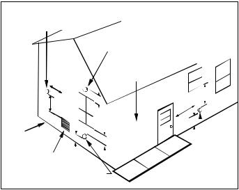
Most homes will require outside air be supplied to the furnace area by means of ventilation grilles or ducts connecting directly to the outdoors or spaces open to the outdoors such as attics or crawl spaces.
INSTALLATION POSITIONS
|
|
|
|
|
|
|
|
|
|
|
|
|
|
|
|
|
|
|
|
|
|
|
|
|
|
|
|
|
|
|
|
|
|
|
|
|
|
|
|
|
|
|
|
|
|
|
|
|
|
|
|
|
|
|
|
|
|
|
|
|
|
|
|
|
|
|
|
|
|
|
|
|
|
|
|
|
|
|
|
|
|
|
|
|
|
|
|
|
|
|
Figure 2A |
|
|
Figure 2B |
|
|
Figure 2C |
||||||
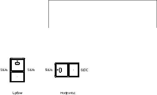
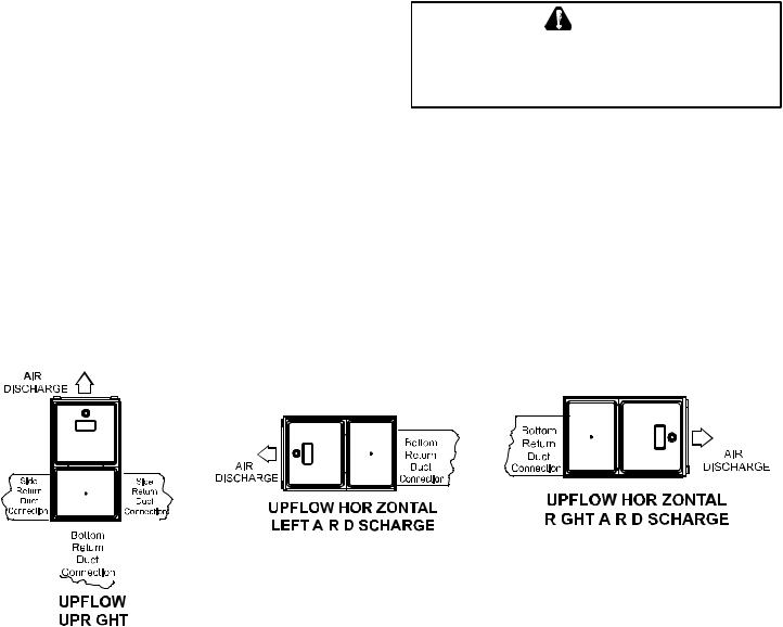
Recommended Installation Positions
*MEC96 models may be installed upflow or horizontally with left or right side down. Do not install this furnace on its back. For upright upflow furnaces, return air ductwork may be attached to the side panel(s) and/or basepan. For horizontal upflow furnaces, return air ductwork must be attached to the basepan. NOTE: Ductwork must never be attached to the back of the furnace. Contact your distributor for proper airflow requirements and number of required ductwork connections. Refer to “Recommended Installation Positions” figure for appropriate installation positions, ductwork connections, and resulting airflow arrangements.
9
HORIZONTAL APPLICATIONS & CONSIDERATIONS
When installing a furnace horizontally, additional consideration must be given to the following:
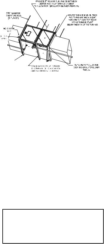
FURNACESUSPENSION
If suspending the furnace from rafters or joists, use 3/8" threaded rod and 2”x2”x1/8” angle iron as shown in the following diagram. The length of rod will depend on the application and the clearances necessary.
If the furnace is installed in a crawl space it must be suspended from the floor joist or supported by a concrete pad. Never install the furnace on the ground or allow it to be exposed to water.
FRONT COVER PRESSURE SWITCH TUBE LOCATION
When a furnace is installed horizontally with left side down, |
|
|
the front cover pressure switch tube must be re-locaed to he |
|
|
lower port of the collector box cover. |
2"X2"X3/8" ANGLE IRON |
|
1. Remove tubefrom front cover pressure switch and collector |
(3 PLACES) |
|
box cover. |
|
|
2. Remove rubber plug from bottom collector box port and |
Figure 2 |
|
install on top of collector box port. |
||
|
3.Locate 24’’ x 1/4’’ tube in bag assembly.
4.Install one end on front cover pressure switch.
5.Route tube to lower port on collector box cover and cut off excess tubing.
DRAIN TRAP AND LINES
In horizontal applications the condensate drain trap is secured to the furnace side panel, suspending it below the furnace. Aminimum clearance of 5.5” below the furnace must be provided for the drain trap. Additionally, the appropriate downward piping slope must be maintained from the drain trap to the drain location. Refer to Condensate Drain Trap and Lines for further details. If the drain trap and drain line will be exposed to temperatures near or below freezing, adequate measures must be taken to prevent condensate from freezing.
HORIZONTAL FURNACE LEVELING
Leveling ensures proper condensate drainage from the heat exchanger. For proper flue pipe drainage, the furnace must be level lengthwise from end to end. The furnace should have a slight tilt from back to front with the access doors downhill from the back panel approximately 1/2 to 3/4 inches. The slight tilt allows the heat exchanger condensate, generated in the recuperator coil, to flow forward to the recuperator coil front cover.
ALTERNATE ELECTRICAL AND GAS LINE CONNECTIONS
This furnace has provisions allowing for electrical and gas line connections through either side panel. In horizontal applications the connections can be made either through the “top” or “bottom” of the furnace.
DRAIN PAN
A drain pan must be provided if the furnace is installed above a conditioned area. The drain pan must cover the entire area under the furnace (and air conditioning coil if applicable).
FREEZE PROTECTION
Refer to Horizontal Applications and Conditions - Drain Trap and Lines.
PROPANE GAS/HIGH ALTITUDE INSTALLATIONS
 WARNING
POSSIBLE PROPERTY DAMAGE, PERSONAL INJURY OR DEATH MAY OCCUR IF THE CORRECT CONVERSION KITS ARE NOT INSTALLED. THE APPROPRIATE KITS MUST BE APPLIED TO ENSURE SAFE AND PROPER FURNACE OPERATION. ALL CONVERSIONS MUST BE PERFORMED BY A QUALIFIED INSTALLER OR SERVICE AGENCY.
This furnace is shipped from the factory configured for natural gas
at standard altitude. Propane gas installations require an orifice and spring change to compensate for the energy content difference between natural and propane gas.
10
High altitude installations may require both |
|
|
|
|
|
|
|
|
|
|
|
|
|
|
|
|
MANIFOLD |
PRESSURE |
PRESSURE |
||||||
a pressure switch and an orifice/spring |
GAS |
ALTITUDE |
KIT |
ORIFICE |
||||||||
change. These changes are necessary to |
HIGH STAGE |
LOW STAGE |
SWITCH CHANGE |
|||||||||
|
|
|
|
|||||||||
compensate for the natural reduction in the |
NATURAL |
|
NONE |
#45 (1) |
3.5" w.c. |
1.9" w.c. |
NONE |
|||||
density of both the gas fuel and the combus- |
0 - 7000 |
#50 (2) |
||||||||||
|
|
|
|
|
|
|
|
|
||||
tion air at higher altitude. For furnaces be- |
|
|
|
|
|
|
|
|
|
|||
|
LPM-08* (1) |
1.25MM (1) |
|
|
|
|
|
|
|
|||
ing converted to LP gas, it is strongly rec- |
PROPANE |
|
10.0" w.c. |
6.0" w.c. |
NONE |
|||||||
|
LPM-30* (2) |
#57 (2) |
||||||||||
ommended that a LPLP03 kit also be in- |
|
|
|
|
|
|
|
|
|
|||
stalled. The use of this kit will prevent |
*supports both Honeywell and White-Rodgers 2-stage valves |
|
|
|
|
|||||||
the furnace from firing when the LP gas |
(1) FOR USE WITH ALL MODELS EXCEPT *MEC960302BN** |
|
|
|
|
|||||||
supply pressure is too low to support |
(2) FOR USE WITH ONLY *MEC960302BN** MODEL |
|
|
|
|
|
|
|
||||
proper combustion. |
|
|
|
|
|
|
|
|
|
|
|
|
|
|
|
|
|
WARNING |
|
|
|
||||
For installations above 7000 feet, please refer to the furnace |
|
|
|
|
|
|||||||
FAILURE TO FOLLOW THESE INSTRUCTIONS CAN RESULT IN BODILY |
||||||||||||
Specification Sheets for required kit(s). |
|
|
||||||||||
|
|
INJURY OR DEATH. CAREFULLY READ AND FOLLOW ALL INSTRUCTIONS |
||||||||||
|
|
|
||||||||||
Contact the distributor for a tabular listing of appropriate |
GIVEN IN THIS SECTION. |
|
|
|
|
|
|
|
||||
manufacturer’s kits for propane gas and/or high altitude installa- |
|
|
|
|
|
|
|
|
|
|||
tions. The indicated kits must be used to insure safe and proper |
|
|
|
|
|
|
|
|
|
|||
|
|
|
|
WARNING |
|
|
||||||
furnace operation. All conversions must be performed by a quali- |
|
|
|
|
|
|
||||||
UPON COMPLETION OF THE FURNACE INSTALLATION, CAREFULLY |
||||||||||||
fied installer, or service agency. |
|
|
||||||||||
VENT/FLUE PIPE & COMBUSTION AIR PIPE |
|
INSPECT THE ENTIRE FLUE SYSTEM BOTH INSIDE AND OUTSIDE OF THE |
||||||||||
|
FURNACE TO ASSURE IT IS PROPERLY SEALED. LEAKS IN THE FLUE |
|||||||||||
A condensing gas furnace achieves its high level of efficiency by |
SYSTEM CAN RESULT IN SERIOUS PERSONAL INJURY OR DEATH DUE TO |
|||||||||||
EXPOSURE TO FLUE PRODUCTS, INCLUDING CARBON MONOXIDE. |
||||||||||||
extracting almost all of the heat from the products of combustion |
|
|
|
|
|
|
|
|
|
|||
and cooling them to the point where condensation takes place. |
|
|
|
|
|
|
|
|
|
|||
Because of the relatively low flue gas temperature and water condensation requirements, PVC or ABS is typically used as venting material.
In addition to PVC and ABS pipe and fittings, Innoflue® by Centrotherm Eco Systems and PolyPro® by M&G Duravent are also approved vent and combustion air materials for installations in the U.S.A. and Canada. Manufacturers Installation instructions for these products must be followed. These products have specific instructions for installing, joining and terminating. Do not mix materials or components of one manufacturer with materials or components of another manufacturer.
All furnaces are built with 2" vent / intake pipe and connectors. For furnaces requiring installation of 3" pipe, the transition from 2" to 3" should be done as close to the furnace as practically possible.
This furnace must not be connected to Type B, BW, or L vent or vent connector, and must not be vented into any portion of a factory built or masonry chimney except when used as a pathway for PVC as described later in this section. Never common vent this appliance with another appliance or use a vent which is used by a solid fuel appliance. Do not use commercially available “no hub connectors” other than those shipped with this product.
It is the responsibility of the installer to follow the manufacturers’ recommendations and to verify that all vent/flue piping and connectors are compatible with furnace flue products. Additionally, it is the responsibility of the installer to ensure that all piping and connections possess adequate structural integrity and support to prevent flue pipe separation, shifting, or sagging during furnace operation.
DUAL CERTIFICATION: NON-DIRECT/DIRECT VENT
This furnace is dual certified and may be installed as a non-direct vent (single pipe) or direct vent (dual pipe) appliance. Anon-direct vent installation requires only a vent/flue pipe, while a direct vent installation requires both a vent/flue pipe and a combustion air intake pipe. Refer to the appropriate section for details concerning piping size, length, number of elbows, furnace connections, and terminations.
MATERIALS AND JOINING METHODS
 WARNING
TO AVOID BODILY INJURY, FIRE OR EXPLOSION, SOLVENT CEMENTS MUST BE KEPT AWAY FROM ALL IGNITION SOURCES (I.E., SPARKS, OPEN FLAMES, AND EXCESSIVE HEAT) AS THEY ARE COMBUSTIBLE LIQUIDS. AVOID BREATHING CEMENT VAPORS OR CONTACT WITH SKIN AND/OR EYES.
Two-three-inch nominal diameter PVC Schedule 40 pipe meeting ASTM D1785, PVC primer meeting ASTM F656, and PVC solvent cement meeting ASTM D2564 specifications must be used. Fittings must be DWV type fittings meeting ASTM D2665 and ASTM D3311. Carefully follow the manufacturer’s instructions for cutting, cleaning, and solvent cementing of PVC.
11

The use of Schedule 40 PVC cellular core DWV meeting ASTM F891-1 or ABS cellular core (Foam Core) plastic pipe is also acceptable as a flue/vent and intake pipe material. PVC primer meeting ASTM F656 and PVC solvent cement meeting ASTM D2564 specifications must be used. Fittings must be DWV type fittings meeting ASTM D2665 and ASTM D3311. Carefully follow the manufactures instructions for cutting, cleaning and solvent cementing of PVC.
For Canadian Installations; field supplied PVC venting materials must be UL S636 listed.
As an alternative to PVC pipe, primer, solvent cement, and fittings, ABS materials which are in compliance with the following specifications may be used. Two-or-three-inch ABS Schedule 40 pipe must meet ASTM D1527 and, if used in Canada, must be CSA listed. Solvent cement for ABS to ABS joints must meet ASTM D2235 and, if used in Canada, must be CSAlisted. The solvent cement for the PVC to ABS transition joint must meet ASTM D3138. Fittings must be DWV type fittings meeting ASTM D2661 andASTM D3311 and, if used in Canada, must be CSA listed. Carefully follow the manufacturers’ instructions for cutting, cleaning, and solvent cementing PVC and/orABS.
All 90° elbows must be medium radius (1/4 bend DWV) or long radius (Long sweep 1/4 bend DWV) types conforming toASTM D3311. A medium radius (1/4 bend DWV) elbow measures 3 1/16” minimum from the plane of one opening to the center line of the other opening for 2” diameter pipe, and 4 9/16” minimum for 3” pipe.
PROPER VENT/FLUE AND COMBUSTION AIR PIPING PRACTICES
Adhere to these instructions to ensure safe and proper furnace performance. The length, diameter, and number of elbows of the vent/ flue pipe and combustion air pipe (when applicable) affects the performance of the furnace and must be carefully sized. All piping must be installed in accordance with local codes and these instructions.
Some models require the use of 3” pipe. Do not transition from a 2” to 3” pipe in a horizontal section of pipe as this may create a water trap.
PREFERRED
ACCEPTABLE
TRANSITION NO LESS
THAN 45 DEGREES TO
HORIZONTAL PLANE TO
AVOID CREATING A WATER
TRAP IN VENT PIPING.
NO TRANSITION ON HORIZONTAL PLANE, THIS CREATES A WATER TRAP AND RESTRICTS FLUE GASES
Figure 4 |
Figure 5 |
Figure 6 |
Piping must be adequately secured and supported to prohibit sagging, joint separation, and/or detachment from the furnace. Horizontal runs of vent/flue piping must be supported every three to five feet and must maintain a 1/4 inch per foot downward slope, back towards the furnace, to properly return condensate to the furnace’s drain system. Allowances should be made for minor expansion and contraction due to temperature variations. For this reason, particular care must be taken to secure piping when a long run is followed by a short offset of less than 40 inches.
Precautions should be taken to prevent condensate from freezing inside the vent/flue pipe and/or at the vent/flue pipe termination. All vent/flue piping exposed to freezing temperatures below 35°F for extended periods of time must be insulated with 1/2” thick closed cell foam. Also all vent/flue piping exposed outdoors in excess of the terminations shown in this manual (or in unheated areas) must be insulated with 1/2” thick closed cell foam. Inspect piping for leaks prior to installing insulation.
TERMINATION LOCATIONS
NOTE: Refer to Location Requirements and Considerations for combustion air contaminant restrictions.
The following bullets and diagram describe the restrictions concerning the appropriate location of vent/flue pipe and combustion air intake pipe (when applicable) terminations. Refer to Non-Direct Vent (Single Pipe) Piping and Direct Vent (Dual Pipe) Piping located in this section for specific details on termination construction.
•All terminations (flue and/or intake) must be located at least 12 inches above ground level or the anticipated snow level.
•Vent terminations (non-direct and direct vent) must terminate at least 3 feet above any forced air inlet located within 10 feet.
NOTE: This provision does not apply to the combustion air intake termination of a direct vent application.
12
•The vent termination of a non-direct vent application must terminate at least 4 feet below, 4 feet horizontally from, or 1 foot above any door, window, or gravity air inlet into any building.
•The vent termination of a direct vent application must terminate at least 12 inches from any opening through which flue gases may enter a building (door, window, or gravity air inlet).
•The vent termination of vent pipe run vertically through a roof must terminate at least 12 inches above the roof line (or the anticipated snow level) and be at least 12 inches from any vertical wall (including any anticipated snow build up).
•A vent termination shall not terminate over public walkways or over an area where condensate or vapor could create a nuisance or hazard or could be detrimental to the operation of regulators, relief valves, or other equipment.
•The combustion air intake termination of a direct vent application should not terminate in an area which is frequently dusty or dirty.
Non-Direct Vent
&
Direct Vent
Vent/Flue Terminations
|
|
|
|
|
|
|
|
|
|
|
|
|
Non-Direct Vent |
|
|
|
|
|
|
|
|
|
|
|
|
|
|
|
|
|||||||
|
|
|
|
|
|
|
|
|
|
|
Vent/Flue Termination |
|
|
|
|
|
|
|
|
|
|
|
|
|
|
|
|
|||||||||
|
|
|
|
|
|
|
|
|
|
|
|
|
|
|
|
|
|
|
|
|
|
|
|
|
|
|
|
|
|
|
|
|
|
|
|
|
|
|
|
|
|
|
|
|
|
|
|
|
|
|
|
|
|
|
|
No Terminations |
|
|
|
|
|
|
|
|
|
|
|
|
|
|
|
||
|
|
|
|
|
|
|
|
|
|
|
|
|
|
|
|
|
|
|
Above Walkway |
|
|
|
|
|
|
|
|
|
|
|
|
|
|
|
||
|
|
|
|
|
|
|
|
|
|
|
|
|
|
|
|
|
|
|
|
|
|
|
|
|
|
|
|
|
|
|
|
|
|
|
|
|
|
|
|
|
|
|
|
|
|
|
|
|
|
|
|
|
|
|
|
|
|
|
|
|
|
|
|
|
|
|
|
|
|
|
|
|
|
|
|
|
|
<10' |
|
|
|
|
12" |
|
|
|
|
|
|
|
|
|
|
|
|
|
|
|
4' |
min. |
|
|||||||||
|
|
3' min. |
|
|
|
|
|
|
|
|
|
|
|
|
|
|
|
|
|
|
|
|
|
|
|
|
|
|
|
|
|
|||||
|
|
|
|
|
|
|
|
|
|
|
|
|
|
|
|
|
|
|
|
|
4' |
|
|
|
|
|
|
|
|
|||||||
|
|
|
|
|
|
|
|
|
|
|
|
|
|
|
|
|
|
|
|
|
|
|
|
|
|
min. |
|
|
|
|
|
|
||||
|
|
|
|
|
|
|
|
|
|
|
|
|
|
|
|
|
|
|
|
|
|
|
|
|
|
|
|
|
|
|
|
|
|
|
|
|
|
|
|
|
|
|
|
|
|
|
|
|
|
|
|
|
|
|
|
|
|
|
|
|
|
12" |
|
|
|
|
|
|
|
|
|||
Grade or Highest |
|
|
|
|
|
|
|
|
|
|
|
|
|
|
|
|
min. |
|
|
|
|
|
|
|
|
|||||||||||
|
|
|
|
|
|
|
|
|
|
|
|
|
|
|
|
|
|
|
|
|
|
|
|
|
|
|||||||||||
|
|
|
12" min. |
|
|
|
|
|
|
|
|
|
|
|
|
|
|
|
|
|
||||||||||||||||
Anticipated |
|
|
|
|
|
|
|
|
|
|
|
|
|
|
|
|
|
|
|
|
|
|
|
|
|
|
|
|
|
|||||||
Snow Level |
|
|
|
|
|
|
|
|
|
|
|
|
|
|
|
|
|
|
|
|
|
|
|
|
|
|
|
|
|
|
|
|
|
|
|
|
|
|
|
|
|
|
|
|
|
|
|
|
|
|
|
|
|
|
|
|
|
|
|
|
|
|
|
|
|
|
|
|
|
|
|
|
|
|
|
|
|
|
|
|
12" min. |
|
|
|
|
|
|
|
|
|
|
|
|
|
|
|
|
|
Non-Direct Vent |
|
||||||||||
|
|
|
|
|
|
|
|
|
|
|
|
|
|
|
|
|
|
|
|
|
|
|
|
|
|
|||||||||||
|
|
|
|
|
|
|
|
|
|
|
|
|
|
|
Vent/Flue Termination |
|||||||||||||||||||||
|
Forced Air |
|
|
|
|
|
|
|
|
|
|
|
|
|
|
|
|
|
|
|
||||||||||||||||
|
|
|
|
|
|
|
|
|
|
|
|
|
|
|
|
|
|
|
|
|||||||||||||||||
|
|
|
|
|
|
|
|
|
|
|
|
|
|
|
|
|
|
|
|
|
||||||||||||||||
|
|
Inlet |
|
|
|
|
|
|
|
|
|
|
|
|
|
|
|
|
|
|
|
|
|
|
|
|
|
|
|
|
|
|
|
|
|
|
|
|
|
|
|
|
|
|
|
|
Direct Vent |
|
|
|
|
|
|
|
|
|
|
|
|
|
|
|
|
||||||||||
|
|
|
|
|
|
|
Vent/Flue Termination |
|
|
|
|
|
|
|
|
|
|
|
|
|
|
|
|
|
|
|
||||||||||
Vent Termination Clearances
NOTE: In Canada, the current edition of CAN/CSA B149.1-15 Figure 7 takes precedence over the preceding termination description.
CANADIAN VENTING REQUIREMENTS
All installations in Canada must conform to the requirements of CAN/CSA B149.1-15 code. All vent system components,including primer and cement, must be listed to ULC S636. The certified pipe and fittings should be clearly marked with the
ULC standard “S636”. The primer and cement used must be of the same manufacturer as the vent system. For Royal Pipe System 636; use GVS-65 Primer (Purple) and GVS-65 PVC Solvent Cement. For IPEX System 636, use PVC/CPVC Primer, Purple or clear. Use PVC Solvent Cement (Gray). For Canadian installations, ABS may be used as a combustion air pipe only. ABS is not an approved vent material in Canada. If ABS is used as a combustion air pipe, it must be CSA certified. Always follow the manufacturer’s instructions in the use of primer and cement. Do not use primer and cement around potential sources of ignition. Do not use primer or cement beyond its expiration date. The safe operation, as defined by ULC S636, of the vent system is based on following these installation instructions, the vent system manufacturer’s installation instructions, and proper use of primer and cement. It is recommended under this standard, that the vent system be checked once a year by qualified service personnel. All fire stops and roof flashings used with this system must be UL listed. Acceptability under CAN/CSA B149.1-15 is dependent upon full compliance with all installation instructions. Consult the authority having jurisdiction (gas inspection authority, municipal building department, fire department, etc.) before installation to determine the need to obtain a permit. *IPEX System 636™ is a trademark of IPEX Inc. Carefully follow the pipe manufacturers’ instructions for cutting, cleaning, and solvent cementing PVC and/or ABS. The vent can be run through an existing unused chimney provided the space between the vent pipe and the chimney is insulated and closed with a weather-tight, corrosion-resistant flashing.
STANDARD FURNACE CONNECTIONS
It is the responsibility of the installer to ensure that the piping connections to the furnace are secure, airtight, and adequately supported.
VENT/FLUE PIPE
The vent pipe outlet is sized to accept 2” pipe. Secure vent/flue pipe directly into the furnace fitting with the appropriate glue. Alternately, a small section of 2" pipe may be glued in the furnace socket and a rubber coupling installed to allow removal for future service. Combustion Air and Vent piping should be routed in a manner to avoid contact with refrigerant lines, metering devices, condensate drain lines, etc. If necessary, clearances may be increased by creating an offset using two 45 degree elbows. This joint can be rotated on the fitting to establish maximum clearance between refrigerant lines, metering devices, and condensate drain lines, etc. This joint is the equivalent of one 90 deg. elbow when considering elbow count. (Figure 8A)
NOTE: For non-direct vent installations, a minimum of one 90° elbow should be installed on the combustion air intake coupling to guard against inadvertent blockage.
13
DIRECTVENTINSTALLATIONS
On upflow units secure the combustion air intake pipe to the air intake coupling by using a take apart rubber coupling supplied with the furnace or a plastic coupling. Also, the intake coupling may be inverted to allow the intake pipe to be glued directly to it. After inverting the coupling, secure it to the furnace top with screws. On counterflow units secure the combustion air intake pipe to the air intake coupling using the rubber coupling and worm gear hose clamps provided with the unit. The counterflow rubber coupling allows service removal of air intake piping internal to the furnace blower compartment. The combustion air intake pipe can also be secured directly to the counterflow unit air intake pipe coupling.
COMBUSTION AIR INTAKE OPTION: The RF000142 coupling can be secured directly to the furnace intake coupling if condensation is a concern. If the RF000142 is used on the combustion air inlet, it must be installed with the arrow pointing up. It should be noted, the combustion air will actually be moving in a direction opposite of the arrow on the RF000142 coupling. It must have a field supplied, trapped drain tube free-draining to proper condensate disposal location. A loop in the drain tube can serve as a trap. The unused RF000142 drain fitting should be capped. (Figure 8B)
NON-DIRECTVENTINSTALLATIONS
V
E
N
T
45 DEGREE LONG-SWEEP ELBOWS
Increased Clearance Configuration
Figure 8A
 VENT-DRAIN
A minimum of one 90° elbow should be installed on the combustion air intake “coupling” to guard against inadvertent blockage.
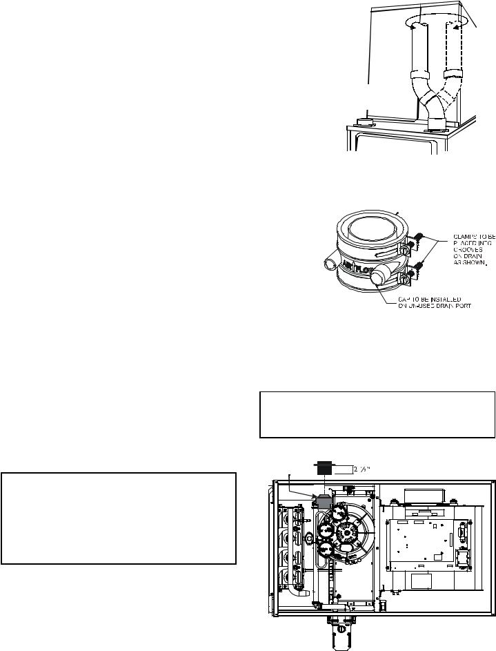
ALTERNATE VENT/FLUE LOCATION
The alternate vent/flue location is the large hole directly in line with the induced draft blower outlet. To use the alternate vent/flue location refer to the following steps and the “Alternate Vent/Flue Location” figure.
The RF000142 Coupling
Figure 8B
NOTE: In the horizontal left installation position, a means of condensate collection must be provided to keep vent pipe condensate from entering the draft inducer housing. If the vent drain elbow is eliminated from the installation, an RF000142 kit must be used.
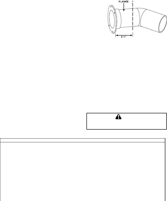
1.Remove the four screws from the vent pipe flange on top the furnace.
2.Remove the internal elbow and vent pipe
3.Cut 2 1/2" from the flange .
4.Remove plastic plug in line with the inducer outlet
5.Install cut end of the flanged section and connect to inducer with rubber coupling supplied with furnace.
6.Install screws removed in step 1 securing flange to cabinet.
 WARNING
THE RUBBER ELBOW IS NOT DESIGNED TO SUPPORT A LOAD. WHEN THE RUBBER ELBOW IS MOUNTED EXTERNALLY TO THE FURNACE CABINET,
EXTREME CARE MUST BE TAKEN TO ADEQUATELY SUPPORT FIELD-
SUPPLIED VENT/FLUE PIPING, AS DAMAGE CAN RESULT IN LEAKS CAUSING BODILY INJURY OR DEATH DUE TO EXPOSURE TO FLUE GASES,
INCLUDING CARBON MONOXIDE
ALTERNATE COMBUSTION AIR PROVISION
(Upflow / Horizontal models only)
When using the alternate venting location, either in a horizontal left side down installation or a vertical installation using down – venting, an alternate combustion air opening can
 WARNING
EDGES OF SHEET METAL HOLES MAY BE SHARP. USE GLOVES AS A PRECAUTION WHEN REMOVING HOLE PLUGS.
Insert flange. Cut 2 ½” long.
RF000142 |
Figure 9
14
be used. A locating dimple is located on the right side of the furnace cabinet. The locating dimple is 1 7/8" measured from the front edge of the cabinet in line with the knock out. To use the alternate combustion air location:
1. Remove screws and combustion air flange from cabinet.
2. |
Insert cabinet plug in unused combustion air hole. |
|
|
3. |
Drill a pilot hole at the cabinet dimple (size dictated by knockout tool |
|
|
|
used). |
|
|
4. |
Use a knockout tool to create a 3" diameter hole |
E |
|
R |
|||
|
|
||
5. |
Install combustion air flange and secure with screws removed in step one. |
E |
|
H |
|||
|
|
T |
|
|
|
U |
|
|
|
C |
NON-DIRECT VENT (SINGLE PIPE) PIPING
Non-direct vent installations require only a vent/flue pipe. The vent pipe can be run horizontally with an exit through the side of the building or run vertically with an
exit through the roof of the building. The vent can also be run through an existing unused chimney; however, it must extend a minimum of 12 inches above the top of
the chimney. The space between the vent pipe and the chimney must be closed with a weather-tight, corrosion-resistant flashing.
Although non-direct vent installations do not require a combustion air intake pipe, a minimum of one 90° elbow should be attached to the furnace’s combustion air intake if: an upright installation uses the standard intake location, or a horizontal installation uses the alternate air intake location. This elbow will guard against inadvertent blockage of the air intake.
VENT/FLUE PIPE LENGTHS AND DIAMETERS
For installations at or above 7,000 feet altitude, use 3” venting. Refer to the following table for applicable length, elbows, and pipe diameter for construction of the vent/flue pipe system of a non-direct vent installation. In addition to the vent/flue pipe, a single 90° elbow should be secured to the combustion air intake to prevent inadvertent blockage. The tee used in the vent/flue termination must be included when determining the number of elbows in the piping system.
1.Maximum allowable limits listed on individual lengths for inlet and flue and NOT a combination.
2.Minimum requirement for each vent pipe if five (5) feet in length and one elbow/tee.
3.Tee used in the vent/flue termination must be included when determining the number of elbows in the piping system.
4. 2 1/2” or 3” diameter pipe can be used in place of 2” diameter pipe.
5. Increased Clearance Configuration using (2) 45 deg. Long Sweep elbows should be considered equivalent to one 90 deg. elbow.
6.One 90° elbow should be secured to the combustion air intake connection.
*M E C 9 6 D i r e c t V e n t (2 - P i p e ) a n d N o n -D i r e c t V e n t (1 - P i p e ) ( 6 )
M a x i m u m A l l o w a b l e L e n g t h o f V e n t / F l u e P i p e
U n i t In p u t (B t u ) |
P i p e S i z e |
|
|
|
N u m b e r o f E l b o w s ( 3 ) ( 5 ) |
|
|
|
|||
( 4 ) (i n .) |
|
|
|
|
|
|
|
|
|
|
|
|
1 |
2 |
3 |
|
4 |
5 |
|
6 |
7 |
8 |
|
*M E C 9 6 0 3 0 2 B N ** |
2 o r 2 1 / 2 |
1 0 0 |
9 5 |
9 0 |
|
8 5 |
8 0 |
|
7 5 |
7 0 |
6 5 |
|
|
|
|
|
|
|
|
|
|
|
|
*M E C 9 6 0 4 0 2 B N ** |
3 |
1 6 8 |
1 6 1 |
1 5 4 |
|
1 4 7 |
1 4 0 |
|
1 3 3 |
1 2 6 |
1 1 9 |
|
|
|
|
|
|
|
|
|
|
|
|
|
2 ^ |
5 0 |
4 5 |
4 0 |
|
3 5 |
3 0 |
|
2 5 |
2 0 |
1 5 |
*M E C 9 6 0 6 0 3 B N ** |
o r 2 1 / 2 ^ |
|
|
||||||||
|
|
|
|
|
|
|
|
|
|
||
|
3 |
1 4 3 |
1 3 6 |
1 2 9 |
|
1 2 2 |
1 1 5 |
|
1 0 8 |
1 0 1 |
9 4 |
|
|
|
|
|
|
|
|
|
|
|
|
*M E C 9 6 0 8 0 3 B N ** |
2 o r 2 1 / 2 |
6 0 |
5 5 |
5 0 |
|
4 5 |
4 0 |
|
3 5 |
3 0 |
2 5 |
|
|
|
|
|
|
|
|
|
|
|
|
3 |
1 1 3 |
1 0 6 |
9 9 |
|
9 2 |
8 5 |
|
7 8 |
7 1 |
6 4 |
|
|
|
|
|||||||||
|
|
|
|
|
|
|
|
|
|
|
|
*M E C 9 6 0 8 0 4 C N ** |
2 o r 2 1 / 2 |
6 0 |
5 5 |
5 0 |
|
4 5 |
4 0 |
|
3 5 |
3 0 |
2 5 |
|
|
|
|
|
|
|
|
|
|
|
|
3 |
1 2 0 |
1 1 3 |
1 0 6 |
|
9 9 |
9 2 |
|
8 5 |
7 8 |
7 1 |
|
|
|
|
|||||||||
|
|
|
|
|
|
|
|
|
|
|
|
*M E C 9 6 1 0 0 4 C N ** |
2 o r 2 1 / 2 |
4 5 |
4 0 |
3 5 |
|
3 0 |
2 5 |
|
2 0 |
1 5 |
1 0 |
|
|
|
|
|
|
|
|
|
|
|
|
3 |
1 0 3 |
9 6 |
8 9 |
|
8 2 |
7 5 |
|
6 7 |
6 0 |
5 3 |
|
|
|
|
|||||||||
|
|
|
|
|
|
|
|
|
|
|
|
*M E C 9 6 1 0 0 5 C N ** |
2 o r 2 1 / 2 |
4 5 |
4 0 |
3 5 |
|
3 0 |
2 5 |
|
2 0 |
1 5 |
1 0 |
|
|
|
|
|
|
|
|
|
|
|
|
3 |
1 5 1 |
1 4 4 |
1 3 7 |
|
1 3 0 |
1 2 3 |
|
1 1 6 |
1 0 9 |
1 0 2 |
|
|
|
|
|||||||||
|
|
|
|
|
|
|
|
|
|
|
|
*M E C 9 6 1 2 0 5 D N ** |
3 |
1 8 5 |
1 7 8 |
1 7 1 |
|
1 6 4 |
1 5 7 |
|
1 5 0 |
1 4 3 |
1 3 6 |
|
|
|
|
|
|
|
|
|
|
|
|
F o r i n s ta l l a ti o n s a t 7 ,0 0 0 o r a b o v e u s e 3 " v e n ti n g ^ * M E C 9 6 0 6 0 3 B N - a d d 4 5 ' o f 2 " p i p e fo r u p fl o w
15
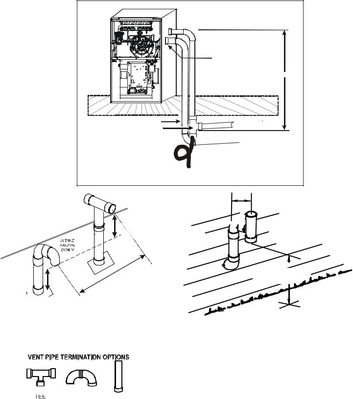
DOWN VENTING UPFLOW MODEL FURNACES ONLY
Figure 11
Use alternate vent
& combination air locations
 Vent Pipe 6’ MAX.
|
|
|
r |
|
|
o |
|
|
lo |
|
|
|
F |
|
|
Combustion Air Pipe |
|
|
Both Pipes Terminated |
Field Supplied |
|
|
Outside Structure |
|
|
|
|
Drain Tee on Vent Pipe |
|
|
|
|
|
|
|
|
|
|
|
|
|
|
|
|
e |
|
|
|
|
|
|
|
|
|
|
|
|
c |
|
|
|
|
|
|
|
|
|
|
|
|
a |
|
|
|
|
|
|
|
|
|
|
|
|
p |
|
|
|
|
|
|
|
|
|
|
|
|
ls |
|
|
|
|
|
|
|
|
|
|
|
|
w |
|
|
|
|
|
|
|
|
|
|
|
|
ra |
|
|
|
|
|
|
|
|
|
|
|
|
t/C |
|
|
|
|
|
|
|
|
|
|
|
|
n |
|
|
|
|
|
|
|
|
|
|
|
|
e |
|
|
|
|
|
|
|
|
|
|
|
|
m |
|
|
|
|
|
|
|
|
|
|
|
|
e |
|
|
|
|
|
|
|
|
|
|
|
|
s |
|
|
|
|
|
|
|
|
|
|
|
|
a |
|
|
|
|
|
|
|
|
|
|
|
|
|
B |
|
|
|
|
|
|
|
|
|
|
|
|
|
 1/4” per foot min. slope
Condensate trapped
to prevent flue gas from escaping and routed to field supplied condensate disposal
All piping and fittings must be joined per material manufacturer’s specifications to prevent separation and flue gas leaks.
|
|
|
|
|
|
|
|
TEE (OPTIONAL) |
|||||||
|
COMBUSTION AIR INTAKE |
|
|
|
|
|
|
|
12” MIN |
||||||
|
|
|
|
|
(OPTIONAL) |
|
|
|
|
|
|
|
HEIGHT DIFFERENCE |
||
|
|
|
|
|
*Not required for |
|
|
|
|
|
|
|
BETWEEN |
||
|
|
|
|
single pipe installation |
|
|
|
|
|
|
|
INTAKE AND VENT |
|||
|
|
|
|
|
E |
|
|
|
|
|
|
|
|
|
|
|
|
|
|
IN |
|
|
|
|
|
|
|
|
|
|
|
|
|
|
L |
|
|
|
|
|
|
|
|
|
|
|
|
|
|
F |
|
|
|
|
|
|
|
|
|
|
|
|
|
|
O |
|
|
|
|
|
|
|
|
|
|
|
|
|
|
O |
|
|
|
|
|
|
|
|
|
|
|
|
|
|
|
R |
|
|
|
|
|
|
|
|
|
|
|
|
|
|
|
|
|
|
|
|
|
|
|
|
|
|
|
|
|
|
. |
|
|
|
|
|
|
|
|
|
|
|
|
|
|
N |
|
|
|
|
|
|
|
|
|
|
|
|
|
|
|
I |
|
|
|
|
|
|
|
|
|
|
|
|
|
|
|
M |
|
|
|
|
|
|
|
|
|
|
|
|
|
|
” |
|
|
|
|
|
|
|
|
|
|
|
|
|
|
3 |
|
|
|
|
|
|
|
|
|
|
|
|
|
|
- |
|
|
|
|
|
|
|
|
|
|
|
|
|
|
. |
|
|
|
|
|
|
|
|
|
|
|
|
|
|
X |
|
|
|
|
|
|
|
|
|
|
|
|
|
|
A |
|
|
|
|
|
|
|
|
|
|
|
|
|
|
|
M |
|
|
|
|
|
|
|
|
|
|
|
|
|
|
” |
|
|
|
|
|
|
|
|
|
|
|
|
|
|
6 |
|
|
|
|
|
|
|
|
|
|
|
|
|
|
|
9 |
|
|
|
|
|
|
|
|
|
12” MIN TO ROOF OR HIGHEST ANTICIPATED SNOW LEVEL
Figure 12
12" MIN.


 VENT/FLUE TEE (OPTIONAL)
or
45° ELBOW
TURNED DOWN or 90° ELBOW TURNED DOWN
12" MIN. ABOVE HIGHEST ANTICIPATED
SNOW LEVEL
Horizontal Termination (Single Pipe)
Above Highest Anticipated Snow
Level
Figure 14
ELBOWS STRAIGHT
Figure 13
16
 Loading...