


Replacement Parts List No. 0700017600
Revision AC 09/2015
Daikin
Daikin McQuay
McQuay
MagnitudeTM
Magnetic Bearing
Centrifugal Chiller
WME
0500
To find your Daikin Applied parts distributor, call 1-800-377-2787 or visit www.DaikinApplied.com
|
Contents |
|
Parts List Revision History ............................................................................................................................. |
3 |
|
Unit Nomenclature |
|
|
|
Model Number Nomenclature ......................................................................................................................... |
4 |
|
Serial Number Nomenclature ......................................................................................................................... |
4 |
|
Model NumberComplete ........................................................................................................................ |
5- 10 |
Electrical Legend ............................................................................................................................................ |
11 |
|
Controls |
|
|
|
Main Control Box ....................................................................................................................................... |
12 |
|
VFD Enclosure .......................................................................................................................................... |
13 |
|
VFD Chassis......................................................................................................................................... |
14, 15 |
|
Compressor Wiring Harness...................................................................................................................... |
15 |
|
VFD Power Supply Plate ..................................................................................................................... |
16, 17 |
|
OITSOperator Interface Touch Screen Panel and Rapid Restore............................................................ |
18 |
Control Sensors |
|
|
|
087 Impeller Units Sensor Location Diagrams .......................................................................................... |
19 |
|
092 Impeller Units Sensor Location Diagrams .......................................................................................... |
20 |
|
Components .............................................................................................................................................. |
21 |
Compressor |
|
|
|
Motor/Bearing Assemblies ......................................................................................................................... |
22 |
|
Motor/Bearing Assembly Components ...................................................................................................... |
23 |
|
087 Impeller- (Compressor Revision/Code 07= AAA) |
|
|
Impeller Assembly ............................................................................................................................... |
24 |
|
Impeller Seal & Compressor Fittings ............................................................................................. |
25, 26 |
|
Discharge Housing & High Speed Shaft Seal ..................................................................................... |
27 |
|
Inlet Assembly ............................................................................................................................... |
28, 29 |
|
092 Impeller- (Compressor Revision/Code 07= AAB) |
|
|
Impeller Assembly ............................................................................................................................... |
30 |
|
Impeller Seal & Compressor Fittings ............................................................................................. |
31, 32 |
|
Discharge Housing & High Speed Shaft Seal ..................................................................................... |
33 |
|
Inlet Assembly ............................................................................................................................... |
34, 35 |
Unit Assembly |
|
|
|
Relief & Shutoff Valves ........................................................................................................................ |
36, 37 |
|
Discharge Piping Stack ....................................................................................................................... |
38, 39 |
|
Hot Gas Bypass 092 Impeller............................................................................................................... |
40, 41 |
|
Suction Piping ...................................................................................................................................... |
42, 43 |
|
Liquid Injection ........................................................................................................................................... |
44 |
|
Rotor Cooling 087 Impeller .................................................................................................................. |
45, 46 |
|
Rotor Cooling 092 Impeller .................................................................................................................. |
47- 49 |
|
Stator Cooling 087 Impeller ................................................................................................................. |
50, 51 |
|
Stator Cooling 092 Impeller ................................................................................................................. |
52, 53 |
|
VFD Cooling .............................................................................................................................................. |
54 |
|
Liquid Line ........................................................................................................................................... |
55, 56 |
Condenser |
|
|
|
Diagrams ................................................................................................................................................... |
57 |
|
26" Condenser Heads, Head Gaskets & Hardware ............................................................................. |
58, 59 |
|
30" Condenser Heads, Head Gaskets & Hardware ............................................................................. |
60, 61 |
|
Tube Counts, Tubes, Sight Glass, Shut Off Valve & Gasket, Charge Valve & Cap ................................... |
62 |
Evaporator |
|
|
|
Diagrams ................................................................................................................................................... |
63 |
|
30" Evaporator Heads, Head Gaskets & Hardware ............................................................................. |
64, 65 |
|
36" Evaporator Heads, Head Gaskets & Hardware ............................................................................. |
66, 67 |
|
Tube Counts, Tubes, Sight Glass, Charge Valve & Cap ........................................................................... |
68 |
Critical Parts List........................................................................................................................................ |
CPL1 |
|
WME0500SWater Cooled Chiller |
Rev. AC 09/15 |
RPL 7000176 / Page 2 |
|
|
Parts List Revision History |
|
|
|
Revision |
Date |
Description |
A- L |
01/12 |
Archived Revisions A thru L. |
M |
01/12 |
Page 10: Changed Ref #8 300047103 to 333568101; Ref #9 300047104 to 333568201; Ref #11 |
|
|
300047105 to 333568301; Ref #13 300047106 to 333568401. |
|
|
Page 11: Deleted duplicate Bub #11. Added new Bub #1 for 2nd VFD fan. Change Ref #5, 6 qty. from 1 to 2. |
|
|
Page 26: Switched Bub #s 204 & 205 to correct locations on upper right dwg. |
|
|
Page 33: Switched Bub #s 204 & 205 to correct locations on upper right dwg. Changed Bub #219 to 222. |
|
|
Page 43: Changed Bub #032 to 052. |
|
|
Page 47: Added Ref #060 ValveBall 330286001 qty. 1pc. |
|
|
Page 56: Changed Ref #355 p/n 070304605 to 070304646. |
|
|
Page 58, 61: Changed Ref #355 p/n 070304606 to 070304621. |
|
|
Page 58, 61, 62: Changed Ref #366 p/n 074521621 to 333850007. |
|
|
Page 63: Changed Ref #355 p/n 070304607 to 070304622. |
|
|
Page 63, 64: Changed Ref #366 p/n 074521622 to 333850008. |
N |
02/12 |
Page 20: Changed Compressor p/n 331799126 to 331799216. |
P |
03/12 |
Cover & Page 3: Updated to Daikin McQuay logo format. |
|
|
Page 13: Added Harness p/n 331795502 & dwg. Updated TOC. |
|
|
Page 31: Added 4/12 & Later Ref #505 Inlet Assy. p/n 331584412. |
|
|
Page 34: Added "4/12 & Later" p/ns for Ref 202, 204, 210, & 218. Added footnote #3. |
|
|
Page 36: Updated drawing for Valve detail. |
|
|
Page 37: Replaced obsolete Ref #21 S/O valves with current p/n:332422302. Re-wrote footnote #3. |
|
|
Page 55, 60: Updated Water Box dwg. Removed component Bubs, except for gaskets. Renumbered Bubs. |
|
|
Page 5658, 6164 (Old) 6265 (New): Removed Water Box components except gaskets. UpdatedWater |
|
|
Box gaskets to reflect change to 2pc. design Ref #352 & 366. Renumbered Bubs to match Water Box |
|
|
dwg. Added footnotes 1- 4. |
|
|
Page 59 (New):Added new page for 30" Cond 3 Pass Water Box components. Repaginated form and |
|
|
updated TOC. |
Q |
03/12 |
Page 5- 8 : Updated Code Nomenclature to R333699001 Rev 0A. |
|
|
Page 9, 10 (NEW):Added 2 pages for additional codes. Repaginated form and updated TOC. |
|
|
Page 60, 66 (OLD), 62, 68 (NEW): Deleted theTube Count table. Added note to refer to Nomenclature |
|
|
section. Re-numbered footnotes as needed. |
R |
05/12 |
Page 12: Changed BACNet kit from 332356901 to 332356951, Lon Kit from 332356902 to 332356952, |
|
|
Modbus kit 332356903 to 332356953. |
|
|
Page 29, 36 (OLD) 35 (NEW): Deleted original footnote #1. Renumbered remaining footnotes. |
|
|
Pages 30, 37: Deleted pages. Repaginated form and updatedTOC. |
|
|
Page 36 (OLD) 35 (NEW): Changed Ref #207 IGVActuator assy. from 331584401 to direct replacement |
|
|
Actuator assembly 331553401. |
S |
7/12 |
Various: Changed "McQuay Parts" to "Daikin McQuay Parts." |
|
|
Page 35: Changed ref #207 p/n from "331553401" to " 331584401". |
T |
7/12 |
Page 5- 10: Updated Coding to Rev. B. |
|
|
Page 15: Added Snubber Capacitor p/n 300048940, qty. of 6. |
U |
8/12 |
Page 13: Added KAIC ratings to ref #8, CBKR. Re-arranged order of ref #8 per KAIC rating. |
V |
9/12 |
Page 37: Changed Ref #021 from "332422302" to "735039964". |
W |
12/12 |
Page 5- 10: Updated Coding to Rev 0F. |
|
|
Page 12:Added HGBP IGV Stepper Board p/n 333568302 and new footnote #1. Updated old footnote #1 to 2. |
|
|
Page 13: Corrected footnote notation for Ref #11. |
|
|
Page 21: Changed Ref #S11 from 071568501 to 071568511. |
|
|
Page 40, 41 (NEW):Added pages for HGBP option. Repaginated form and updated TOC. |
Y |
06/13 |
Page 12: Deleted Ref #15 p/n and Bub #. Duplicate number. |
Z |
08/13 |
Page 21: Added footnote #2 and footnote notation. |
AA |
12/13 |
Page 17: Changed Ref. S09 Sensor Liquid LineTemp to 073007203, was 331795205. |
|
|
Pages 5861 and 6467: Updated Water Box Head Gaskets from 2 part numbers to kit part numbers. |
AB |
08/14 |
Page 8: Added Rapid Restore to Code 31. |
|
|
Page 13: Corrected information for Solenoid Valve and Coil. Expanded Ref. 5 to 5A, 5B, 5C; added 5A |
|
|
Valve-Solenoid, corrected 5B Coil-Solenoid (was p/n 300047095), and added 5C Repair Kit-Solenoid |
|
|
Valve. |
|
|
Page 18: Added Rapid Restore to drawing, added part number for Rapid Restore Kit. Clarified information |
|
|
in footnote 1. |
|
|
Page 58: Added chart for Cond Heads, etc. for 300 PSIG (Code 19= C5). |
AC |
09/2015 |
Page 14: Added Bubble Ref. 16. |
|
|
Page 15: Added Backup Battery for VFD Controller and Ref. 16 Wire Harness/Cable Kit and Footnote #2. |
|
|
Page 21: Updated p/n for S07 & S13 Sensors, was 071568601. Updated p/n for S11, was 071568511. |
|
|
Page 23: Changed Ref. 8 to 8A.Added p/n and Bubble for Ref. 8B. Removed Footnote 3. |
|
|
Page 32: Added footnote #4 to Ref. 505. |
|
|
Page 53: Corrected p/n for Ref. 026 Coil-Sol Valve, was 331796054. |
|
|
Pages 57 & 62:Added Bub. Ref. 252 (Screw) and 253 (Gasket). |
|
|
Page 68: Corrected p/n for Ref. 331, was 073249901. |
|
|
CPL1: Added Critical Parts List. |
|
|
|
Daikin Applied, 13600 Industrial Park Blvd., P.O. Box 1551, Minneapolis, MN 55440 (763) 553-5330
WME0500SWater Cooled Chiller |
Rev. AC 09/15 |
RPL 7000176 / Page 3 |
Nomenclature
Model and Serial Number Nomenclature
Model Number Nomenclature
|
|
|
WME 0500 |
S |
||||||||
Unit Type: |
|
|
|
|
|
|
|
|
|
|
|
Number of Compressors |
|
|
|
|
|
|
|
|
|
|
|||
WME = Magnetic Bearing Centrifugal Chiller, |
|
|
|
|
|
S = Single Compressor |
||||||
Water Cooled |
|
|
|
|
|
|
||||||
|
Unit Size: |
|
|
|
|
|
|
|
||||
|
|
|
|
|
|
|
|
|||||
|
500 Nominal Tons |
|
|
|
|
|
||||||
|
|
|
|
Serial Number Nomenclature |
|
|
|||||||||||||||
|
|
STN |
U |
09 |
05 |
|
04810 |
|
|
|
|||||||||||
Plant Identification |
|
|
|
|
|
|
|
|
|
|
|
|
|
|
|
|
|
|
|
Serial Number |
|
|
|
|
|
|
|
|
|
|
|
|
|
|
|
|
|
|
|
|
|||
STN = Staunton, VA |
|
|
|
|
|
|
|
|
|
|
|
|
|
|
|
|
(Build Sequence) |
||||
U = Unit |
|
|
|
|
|
|
|
|
|
|
|
|
|
|
|
|
|
|
Month of Manufacture |
||
|
|
|
|
|
|
|
|
|
|
|
|
|
|
|
|
|
|
||||
|
|
|
|
|
|
|
|
|
|
|
|
|
01 |
= January |
|||||||
|
|
|
|
|
Year of Manufacture |
||||||||||||||||
|
|
|
|
|
02 |
= February |
|||||||||||||||
|
|
|
|
|
09 |
= 2009 |
|
|
|
|
03 |
= March |
|||||||||
|
|
|
|
|
10 |
= 2010 |
|
|
|
|
04 |
= April |
|||||||||
|
|
|
|
|
11 |
= 2011 |
|
|
|
|
05 |
= May |
|||||||||
|
|
|
|
|
12 |
= 2012 |
|
|
|
|
06 |
= June |
|||||||||
|
|
|
|
|
|
|
|
|
etc. |
|
|
|
|
07 |
= July |
||||||
|
|
|
|
|
|
|
|
|
|
|
|
|
|
|
08 |
= August |
|||||
|
|
|
|
|
|
|
|
|
|
|
|
|
|
|
09 |
= September |
|||||
|
|
|
|
|
|
|
|
|
|
|
|
|
|
|
10 |
= October |
|||||
|
|
|
|
|
|
|
|
|
|
|
|
|
|
|
|
|
|
|
11 = November |
||
|
|
|
|
|
|
|
|
|
|
|
|
|
|
|
12 |
= December |
|||||
WME0500SWater Cooled Chiller |
Rev. AC 09/15 |
RPL 7000176 / Page 4 |
Nomenclature
Model NumberComplete
Code: |
WME 0500S S M2 |
S |
S |
AAB E3012 BE |
2RA |
C4 0440 |
CC |
Y |
A |
C3012 |
BLYY |
||||||||||||
Code No.: |
1 |
|
2 |
3 |
4 |
5 |
6 |
7 |
|
8 |
|
9 |
10 |
11 |
12 |
13 14 |
15 |
16 |
|
17 |
|||
|
2RA |
C4 |
1050 |
CC |
Y |
A |
A |
134 |
082 |
E1 |
|
YY |
EAYYYY |
YYYYYYYY |
YYYY |
||||||||
|
18 |
19 |
20 |
21 |
22 |
23 |
24 |
25 |
26 |
27 |
|
28 |
|
29 |
|
|
30 |
|
31 |
||||
|
H2 |
B |
1 |
4 |
A |
Y |
Y |
Y |
1 |
B |
A |
0150 |
U |
|
Y |
Y Y Y Y Y |
Y 0 |
A VFDM |
|||||
|
32 |
33 |
34 |
35 |
36 |
37 |
38 |
39 |
40 |
41 |
42 |
|
43 |
44 |
45 |
46 47 48 48 49 50 51 |
52 |
53 |
|||||
|
400 |
S |
YYYY |
Y |
YY |
S |
AA |
ST |
0000 |
0000 |
YY |
YY |
YY |
|
N1 |
UM |
C2 |
||||||
|
54 |
55 |
|
56 |
57 |
58 |
59 |
60 |
61 |
|
62 |
|
63 |
64 |
65 |
66 |
|
67 |
68 |
69 |
|||
|
05S |
YY |
YY |
0000 |
0000 |
Y |
|
|
|
|
|
|
|
|
|
|
|
|
|
|
|||
|
70 |
71 |
72 |
73 |
|
74 |
75 |
|
|
|
|
|
|
|
|
|
|
|
|
|
|
||
1. Model Type
WME= Magnetic Bearing Centrifugal Chiller, Water Cooled
2.Unit Size / Number of Compressors
First 4 Digits= Unit Size in Nominal Tons
0500= 500 Ton
Fifth Digit= Number of Compressors
S= Single Compressor
3.Refrigerant Circuiting
S= Single Circuit
4. Motor Code
M2= 3 Winding, 3PH, 440575V; M3= 1 Winding, 6PH, 380575V
5. Voltage Code
U= 380/60; A= 440/60; R= 460/60; S= 480/60; D= 575/60; F 380/50; G= 400/50; K= 415/50
6.Sound Reduction Package
S= Sound Reduction Package
7.Compressor Revision Level
AAA= Compressor Revision Level; AAB= Compressor Revision Level
8. Evaporator Shell Size
E3012= Evaporator, 30" Diameter/12' Long; E3612= Evaporator, 36" Diameter/12' Long
9. Evaporator Tube Count / Tube Type
First Digit= Tube Count; 3/4" Diameter Tube |
|
||
30" Diameter: B= 300; |
C=262; |
X=Special |
|
36" Diameter: B= 488; |
C= 414; |
D= 352; |
X= Special |
First Digit= Tube Count; 1" Diameter Tube |
|
||
30" Diameter: E= 178; |
F= 149; |
X= Special |
|
36" Diameter: E= 271; |
F= 243; |
G= 209; |
X= Special |
First Digit= Tube Count; Mixed Diameter Tube |
|
||
30" Diameter: J= 155; |
K= 127; |
X= Special |
|
36" Diameter: J= 244; |
K= 215; |
M= 179; |
X= Special |
Second Digit= Tube Type |
|
|
|
E=TurboEHP.025Wall,3/4"; F=TurboEHP.028Wall,3/4"; Q=TurboEHP.035Wall,3/4"; T= TCSS 28FPI.028Wall,3/4";
Z= TC Titanium 32FPI .028 Wall, 3/4"; G= CU Turbo .025 Wall, 1"; D= CU Turbo .028 Wall, 1"; H= CU Turbo .035 Wall, 1"; X= Special
WME0500SWater Cooled Chiller |
Rev. AC 09/15 |
RPL 7000176 / Page 5 |
Nomenclature
Model NumberComplete, Continued
10. Evaporator Head / Waterbox Description
First Digit= Number of Water Passes
1= 1 Pass; 2= 2 Pass; 3= 3 Pass; X= Special
Second Digit= Inlet Nozzle Location L= Left; R= Right
Third Digit= Nozzle Configuration
A= Dished Head Victaulic; B= Dished Head Flanged; C= Waterbox Top Victaulic; E= Waterbox Top Flanged; G= Waterbox Rear Victaulic; H= Waterbox Rear Flanged; X= Special
11. Evaporator Design Pressures
C1= Refrigerant Side Pressure: 200 PSIG; Waterside Pressure: 150 PSIG ASME
C2= Refrigerant Side Pressure: 200 PSIG; Waterside Pressure: 250 PSIG ASME C3= Refrigerant Side Pressure: 200 PSIG; Waterside Pressure: 350 PSIG ASME C4= Refrigerant Side Pressure: 200 PSIG; Waterside Pressure: 150 PSIG Non-ASME
C5= Refrigerant Side Pressure: 200 PSIG; Waterside Pressure: 300 PSIG Non-ASME XX= Special
12. Evaporator Leaving Water Temperature
Code is listed in tenths of °F. (Example: 0440= 44.0 °F)
13.Evaporator Tube Sheet & Head Material
First Digit= Tube Sheet Material C= Carbon Steel
N= Monel Clad
S= Stainless Steel Clad
T= Titanium Clad Steel
X= Special
Second Digit= Head Material
C= Carbon Steel
E= Epoxy Coated
X= Special
14.Tube Cleaning System
Y= None
15. Evaporator Revision Level
A= Revision A; B= Revision B
16.Condenser Shell Diameter & Length
C2612= Condenser, 26" Diameter/12' Long
C3012= Condenser, 30" Diameter/12' Long C3612= Condenser, 36" Diameter/12' Long
17.Condenser Tube Type & Count
First Digit= Tube Count; 3/4" Diameter Tube |
|
||
30" Diameter: B= 300; |
C=262; |
X=Special |
|
36" Diameter: B= 488; |
C= 414; |
D= 352; |
X= Special |
First Digit= Tube Count; 1" Diameter Tube |
|
||
26" Diameter: E= 268; |
F= 232; |
X= Special |
|
30" Diameter: E= 339; |
F= 295; |
G= 265; |
X= Special |
36" Diameter: E= 534; |
F= 480; |
G= 417; |
X= Special |
First Digit= Tube Count; Mixed Diameter Tube |
|
||
26" Diameter: E= 268; |
F= 232; |
X= Special |
|
30" Diameter: E= 339; |
F= 295; |
G= 265; |
X= Special |
36" Diameter: E= 534; |
F= 480; |
G= 417; |
X= Special |
Second Digit= Tube Type |
|
|
|
L= Turbo CSL .025 Wall, 3/4"; |
N= Turbo CSL .028 |
Wall, 3/4"; |
P= Turbo CSL .035 Wall, 3/4"; |
T= TC SS 28FPI .028 Wall, 3/4"; Z= TC Titanium 32FPI .028 Wall, 3/4"; 1= 90-10 CU-NI .028 Wall, 3/4"; |
|||
4= 90-10 CU-N .035 Wall, 3/4"; |
A= CU Turbo .025 |
Wall, 1"; |
B= CU Turbo .028 Wall, 1"; C= CU Turbo .035 Wall, 1"; |
X= Special |
|
|
|
Digits 3 & 4
YY= None; XX= Special
WME0500SWater Cooled Chiller |
Rev. AC 09/15 |
RPL 7000176 / Page 6 |
Nomenclature
Model NumberComplete, Continued
18. Condenser Head / Waterbox Description
First Digit= Number of Water Passes
1= 1 Pass; 2= 2 Pass; 3= 3 Pass; X= Special
Second Digit= Inlet Nozzle Location L= Left; R= Right
Third Digit= Nozzle Configuration
A= Dished Head Victaulic; B= Dished Head Flanged; D= Waterbox Top Victaulic; F= Waterbox Top Flanged; G= Waterbox Front Victaulic; H= Waterbox Front Flanged; X= Special
19. Condenser Design Pressures
C1= Refrigerant Side Pressure: 200 PSIG; Waterside Pressure: 150 PSIG ASME
C2= Refrigerant Side Pressure: 200 PSIG; Waterside Pressure: 250 PSIG ASME C3= Refrigerant Side Pressure: 200 PSIG; Waterside Pressure: 350 PSIG ASME C4= Refrigerant Side Pressure: 200 PSIG; Waterside Pressure: 150 PSIG Non-ASME
C5= Refrigerant Side Pressure: 200 PSIG; Waterside Pressure: 300 PSIG Non-ASME XX= Special
20.Maximum Condenser Leaving Water Temperature
Code is listed in tenths of °F. (Example: 1050= 105.0 °F)
21.Condenser Tube Sheet & Head Material
First Digit= Tube Sheet Material
C= Carbon Steel
N= Monel Clad
S= Stainless Steel Clad
T= Titanium Clad Steel
X= Special
Second Digit= Head Material
C= Carbon Steel
E= Epoxy Coated
X= Special
22.Condenser Tube Cleaning System
Y= None
23.Condenser Model Revision
A= Revision A; B= Revision B
24. Pressure Vessel Code
A= ASME; C= PED; P= Chinese; 1= British Columbia; 2= Alberta; 3= Saskatchewan; 4= Manitoba; 5= Ontario; 6= Quebec;
7= New Brunswick; 8= Nova Scotia; 9= Prince Edward Island; 0= Newfoundland; U= Yukon
25.Refrigerant Type
134= R134A Refrigerant
26.Refrigerant Weight
Total Refrigerant weight (lbs.) divided by 10 rounded to the next whole number. (Example: 815/10= 81.5, Round up to 082)
27.Electronic Expansion Valve Circuit #1
E1= Electronic Valve Size 1
28.Electronic Expansion Valve Circuit #2
YY= None
29.MicroTech Controls
EAYYYY= MicroTech-E, Rev. A
30. BAS Card
BMSTPEYY= BACnet; LYYYYYYY= LONmark; MBYYYYYY= Modbus; YYYYYYYY= None
WME0500SWater Cooled Chiller |
Rev. AC 09/15 |
RPL 7000176 / Page 7 |
Nomenclature
Model NumberComplete, Continued
31.Controls Options
YYYY= None RRYY= Rapid Restore
32.Insulation
First Digit= Condenser & Evaporator Shell Insulation
H= ¾" Closed Cell Foam Insulation
3= 1½" Closed Cell Foam Insulation
Y= None
X= Special
Second Digit= Condenser & Evaporator Head Insulation
1= Return Head(s) Only
2= Return & Connection Heads
Y= None
X= Special
33. |
Water Flow Indication |
|
B= Evaporator & Condenser Flow Control; X= Special |
34. |
Paint |
|
1= Standard Paint; X= Special |
35. |
Packaging |
2= Open Export Crate; 3= Totally Enclosed Export Crate; 4= Shipping Bag with Standard Wood Skid;
6= Shipping Bag with Totally Enclosed Export Crate; 7= Shipping Bag with Open Export Crate; X= Special
36.Refrigerant Tag
A= Full Factory Charge; B= Holding Charge R134a; N= Holding Charge, Nitrogen; X= Special
37.Special Features
M= Stock Modification; Y= None; X= Special
38.Not a WME Code Item
Y= None
39.Knockdown Option
1= Compressor & VFD removed, run tested, Nitrogen holding charge; 2= Full Knockdown option, Nitrogen holding charge;
3= Refrigerant in Compressor, Full Factory charge; Y= None; X= Special
40.Testing
Y= None
1= Run test only
2, 9, A, B, C, D, E, F, G, H, J, Q, S= Various Witness Tests
3, 4, 5, 6, 7, K, L, M, N, P, R, T= Various Certified Performance Tests 8= Non certified Sound Test
X= Special
41.Approval Listing
A= AHRI only; B= AHRI/ETL/CETL; C= PED; E= ETL/CETL; N= ARI/OSP-IBC; O= AHRI/ETL/CETL/OSP-IBC;
P= ETL/CETL/OSP-IBC; Q= OSP-IBC; X= Special; Y= None
42.Unit Model Revision
A= Revision A
43.Refrigeration Tons
0000= Data Calculated from Selection Program (Example: 0150= 150 Tons)
44. Startup
U= Domestic Startup; 7= Canadian Startup; Y= Export, No Startup
WME0500SWater Cooled Chiller |
Rev. AC 09/15 |
RPL 7000176 / Page 8 |
Nomenclature
Model NumberComplete, Continued
45. |
First Year Warranty |
|
|
|
Y= Entire Unit Parts + Labor (Standard); C= Entire Unit Parts + Compressor Labor Only; P= Entire Unit Parts Only (Export standard) |
||
46. |
Extended Warranty |
|
|
|
(Codes C thru K apply to Parts and/or Labor for the complete unit.) |
||
|
C= Extended 1 year parts; D= Extended 1 year parts + Labor; E= Extended 2 year parts; F= Extended 2 year parts + Labor; |
||
|
G= Extended 3 year parts; H= Extended 3 year parts + Labor; J= Extended 4 year parts; K= Extended 4 year parts + Labor; |
||
|
(Codes L thru S apply to the Compressor & Drive Train Only.) |
||
|
L= Extended 1 year parts; M= Extended 1 year parts + Labor; N= Extended 2 year parts; O= Extended 2 year parts + Labor; |
||
|
P= Extended 3 year parts; Q= Extended 3 year parts + Labor; R= Extended 4 year parts; S= Extended 4 year parts + Labor; |
||
|
Y= None; |
X= Special |
|
47. |
Order Type |
|
|
|
B= BOM only; |
C= Compressor Kit; M= Modification; R= Retrofit Kit; Y= Standard |
|
4850. Not WME Code Items |
|||
|
Y= None |
|
|
51. |
Refrigerant Warranty |
|
|
|
0= None; 1= One Year; |
2= Two Years; 3= Three Years; 4= Four Years; 5= Five Years |
|
52. |
Delayed Warranty Start |
|
|
|
A= No Additional Months; |
B= Two Additional Months; C= Four Additional Months; D= Six Additional Months; |
|
|
E= Eight Additional Months; F= Ten Additional Months; G= Twelve Additional Months |
||
53. VFD Type |
|
|
|
|
VFDM= VFD Magnetic Bearing Chiller |
||
54. |
VFD Size |
|
|
|
400= 400A VFD Max Output Amps, 6 Phase; 500= 500A VFD Max Output Amps, 3 Phase |
||
55. Power Assembly |
|
||
|
S= Single Power Assembly, 3 Phase; D= Dual Power Assembly, 6 Phase |
||
56. |
Transformer Type |
|
|
|
40SD= 400AAutoTransformer - 3 Phase; 60SU= 600AAutoTransformer - 3 Phase; |
||
|
50SD= 500A Stepdown AutoTransformer - 6 Phase; 73ST= 730AAutoTransformer - 6 Phase; |
||
|
73SU= 730A Stepup AutoTransformer - 6 Phase; YYYY= None |
||
57. |
Power Meter |
|
|
|
M= Power Meter 7350; Y= None; X= Special |
||
58. Not a WME Code Item |
|
||
|
YY= None |
|
|
59. |
Input Voltage, Compressor Motor / Electrical Power (Code 59 MUST= Code 05) |
||
|
U= 380/60; A= 440/60; R= 460/60; S= 480/60; D= 575/60; F 380/50; G= 400/50; K= 415/50 |
||
60. |
Manufacturing Location of VFD |
||
|
AA= Made in the USA; AB= Made in Europe |
||
61. |
Short Circuit Current Rating (SCCR) |
||
|
LL= Short Circuit Current Rating 25KA (use with 575V); ST= Short Circuit Current Rating 35KA; |
||
|
MH= Short Circuit Current Rating 50KA (use with 575V); HH= Short Circuit Current Rating 65KA |
||
|
VH= Short Circuit Current Rating 100KA; XX= Special |
||
62. VFD input RLA Compressor 1
0000= Data Calculated from Selection Program
63. VFD input RLA Compressor 2
0000= Data Calculated from Selection Program (always 0000 unless Code 03= D)
WME0500SWater Cooled Chiller |
Rev. AC 09/15 |
RPL 7000176 / Page 9 |
Nomenclature
Model NumberComplete, Continued
64. EMI Filter
E1= Filter 1 - 400A Input Current; E2= Filter 2 - 600A Input Current; E3= Filter 3; XX= Special; YY= None
65. Harmonic Filter
H1= 300HP; H2= 350HP; H3= 400HP; YY= None
66. Equipment Ground Fault Detection
GF= Ground Fault Detection Relay; YY= None
67.Cabinet Type
N1= Nema 1
68.Cabinet Mounting
UM= Unit Mounted
69.Cabinet Size
C1= Large Cabinet with Transformer; C2= Small Cabinet w/o Transformer
70. Circuit Breaker Rating
04V= 380V - 480V / 400A, 100KA Breaker; |
05S= 380V - 480V / 500A, 35KA Breaker; |
05H= 380V - 480V |
/ 500A, 65KA Breaker; |
06S= 380V - 480V / 600A, 35KA Breaker; |
06H= 380V - 480V / 600A, 65KA Breaker; |
06V= 380V - 480V / 600A, 100KA Breaker; |
|
08S= 380V - 480V / 800A, 35KA Breaker; |
08H= 380V - 480V / 800A, 65KA Breaker; |
08V= 380V - 480V / 800A, 100KA Breaker; |
|
04L= 575V - 400A, 25KA Breaker; |
04M= 575V - 400A, 50KA Breaker; 06L= 575V - 600A, 25KA Breaker; |
06M= 575V - 600A, 50KA Breaker |
|
71.Not a WME Code Item
YY= None
72.Not a WME Code Item
YY= None
73.VFD Output RLA / Overload Setting Compressor 1
0000= Data Calculated from Selection Program
74.VFD Output RLA / Overload Setting Compressor 2
0000= Data Calculated from Selection Program (always 0000 unless Code 03= D)
75. Starter Special
Y= None; X= Special
WME0500SWater Cooled Chiller |
Rev. AC 09/15 |
RPL 7000176 / Page 10 |
Electrical Legend
Sch. Sym. |
Description |
Location |
BAS |
Communication Card |
Main Control Box |
CB1 |
Circuit BreakerTX2 Primary |
VFD Power Supply Plate |
CB2- 4 |
Circuit BreakerFans |
VFD Power Supply Plate |
CB4 |
Circuit BreakerMCB Trip, Power Meter, ELR, Solenoid |
VFD Power Supply Plate |
CFT1CFT2 |
Cooling Fan Control |
VFD Power Supply Plate |
CT1- 6 |
Current Transducers |
VFD Chassis |
CPU |
Main Control Board |
Main Control Box |
D1 |
Diode |
VFD Chassis |
ES |
SwitchEthernet |
Main Control Box |
ELR |
RelayEarth Leakage |
VFD Power Supply Plate |
EMC |
EMC Filter |
VFD Enclosure |
EXV1 |
Electronic Expansion Valve #1 |
Liquid Line |
EXV2 |
Electronic Expansion Valve #2 |
Liquid Line |
F1F2 |
FuseControls Transformer, 2A 600VAC |
VFD Power Supply Plate |
F3F5 |
FuseIPS, 6A 600VAC |
VFD Power Supply Plate |
F6F7 |
Fuse150VDC to DC Power Supply, 10A 600VAC |
VFD Power Supply Plate |
F8F10 |
FusePower Meter, 10A 600VAC |
VFD Power Supply Plate |
INPUT |
I/O Board |
Main Control Box |
IPS |
Intermediate Power Supply |
VFD Enclosure |
L1- 3 |
Chopper Chokes/Inductors |
VFD Chassis |
LCD |
LCD Touch Screen Monitor (OITS) |
Evaporator |
LR |
Line Reactor |
VFD Enclosure |
MCB |
Main Circuit Breaker |
VFD Enclosure |
P1P14 |
DC Power Distribution Terminals |
VFD Power Supply Plate |
PM |
Power and Current Meter |
VFD Power Supply Plate |
PS2PS4 |
Power SupplyVFD |
VFD Power Supply Plate |
PS5 |
Power SupplyChiller I/O |
VFD Power Supply Plate |
PS6 |
Power SupplyCompressor I/O |
VFD Power Supply Plate |
PS7PS8 |
Power SupplyMagnetic Bearings |
VFD Power Supply Plate |
Q1- 3 |
Chopper/IGBT Driver |
VFD Chassis |
Q4- 6 |
Steering Bridge IGBT |
VFD Chassis |
R1- 4 |
Resistors |
VFD Chassis |
S01 |
SensorEvaporator Entering Water Temperature |
Evaporator Inlet |
S02 |
SensorEvaporator Leaving Water Temperature |
Evaporator Outlet |
S04 |
SwitchEvaporator Entering Flow |
Evaporator Inlet |
S05 |
SensorCondenser Entering Water Temperature |
Condenser Inlet |
S06 |
SensorCondenser Leaving Water Temperature |
Condenser Outlet |
S07 |
SensorCondenser Refrigerant Pressure |
Condenser |
S08 |
SwitchCondenser Entering Flow |
Condenser Inlet |
S09 |
SensorLiquid Line Temperature |
Liquid Line |
S10 |
SensorCompressor Suction Temperature |
Compressor |
S11 |
SensorCompressor Suction Pressure |
Compressor |
S12 |
SensorCompressor Discharge Temperature |
Compressor Discharge Housing |
S13 |
SensorCompressor Discharge Pressure |
Compressor Discharge Housing |
S14 |
SensorMotor Gap Temperature |
Compressor |
S15 |
SwitchHigh Pressure |
Discharge Piping |
SW1 |
SwitchCompressor #1 |
Main Control Box |
SW3 |
SwitchRemote Start/Stop |
Remote Mounting |
SW4 |
SwitchMode |
Remote Mounting |
SW5 |
SwitchUnit Enable |
Main Control Box |
TDM1- 3 |
Diode/Thyristor Module |
VFD Chassis |
TS1 |
Thermal Switch |
VFD Chassis |
TH1, 2 |
Thermistors |
VFD Chassis |
TX2 |
Transformer480/240/120 VAC, 500A |
VFD Power Supply Plate |
VFD1 |
VFD Chassis Assembly |
VFD Enclosure |
WME0500SWater Cooled Chiller |
Rev. AC 09/15 |
RPL 7000176 / Page 11 |
Controls
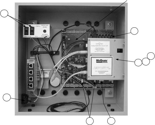
Main Control Box
Communication Card
Location
24
4
9
7 8
18
|
|
13 |
11 |
|
|
|
|
|
|
Ref. |
Schem. |
|
|
|
No. |
Sym. |
Description |
Part No. |
Qty. |
4 |
|
BoardChiller I/O Backplane |
300047099 |
1 |
7 |
CPU |
BoardChiller Controller |
300047102 |
1 |
N/S |
|
Connector, Chiller Controller, Beige |
300048948 |
21 |
N/S |
|
Connector, Chiller Controller, Orange |
300048949 |
4 |
8 |
|
BoardDigital I/O |
333568101 |
1 |
9 |
|
BoardAnalog Output |
333568201 |
1 |
11 |
|
BoardIGV Stepper Motor w/o HGBP 1 |
333568301 |
1 |
11 |
|
BoardIGV Stepper Motor w/ HGBP 1 |
333568302 |
1 |
13 |
|
BoardAnalog Input |
333568401 |
2 |
18 |
SW5 |
SwitchUnit Enable |
300047109 |
1 |
24 |
SW1 |
SwitchUnit and Compressor #1 |
300047110 |
2 |
N/S |
BAS |
BACnet MS/TP/E Installation Kit 2 |
332356951 |
1 |
N/S |
BAS |
Lonmark Installation Kit 2 |
332356952 |
1 |
N/S |
BAS |
Modbus Installation Kit 2 |
332356953 |
1 |
N/S= Not Shown on Diagram.
1Note that Hot Gas Bypass (HGBP) is NOT a coded option. Refer to the HGBP section to aid in confirming the presence of the HGPB option.
2Includes the Communication Card and Installation Manual.
WME0500SWater Cooled Chiller |
Rev. AC 09/15 |
RPL 7000176 / Page 12 |
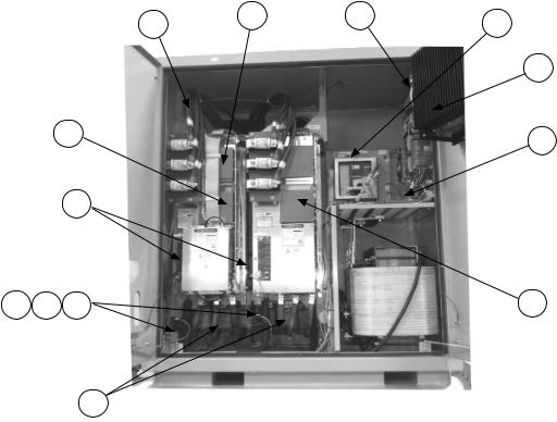
Controls
VFD Enclosure
1 |
3 |
1 |
8 |
|
|
7
3 |
10 |
|
4
5C |
5B |
5A |
11 |
6
Ref. |
Schem. |
|
|
|
|
|
No. |
Sym. |
Description |
|
|
Part No. |
Qty. |
1 |
|
Fan |
120 VAC 600 CFM |
300047091 |
2 |
|
3 |
VFD1 |
VFD Chassis AssemblyPhases 1- 3 1 |
300047093 |
1 |
||
4 |
|
Fuse |
20A/1000VAC |
300047094 |
2 |
|
5A |
|
ValveSolenoid |
|
|
331796001 |
2 |
5B |
|
ValveCoil |
120/60, 10 watt |
331796051 |
2 |
|
5C |
|
Repair KitSolenoid Valve |
|
300052079 |
2 |
|
6 |
LR |
Line Reactor |
|
3PH |
300047096 |
2 |
7 |
IPS |
Intermediate Power Supply |
|
300047097 |
1 |
|
8 |
MCB |
CBKR Molded Case |
25KAIC |
600V 400A |
300048927 |
1 |
|
|
CBKR Molded Case |
25KAIC |
600V 600A |
300048929 |
1 |
|
|
CBKR Molded Case |
35KAIC |
480V 500A |
300047098 |
1 |
|
|
CBKR Molded Case |
35KAIC |
600V 500A |
300047071 |
1 |
|
|
CBKR Molded Case |
35KAIC |
600V 600A |
300047100 |
1 |
|
|
CBKR Molded Case |
35KAIC |
600V 800A |
300048924 |
1 |
|
|
CBKR Molded Case |
50KAIC |
600V 400A |
300048928 |
1 |
|
|
CBKR Molded Case |
50KAIC |
600V 600A |
300048930 |
1 |
|
|
CBKR Molded Case |
65KAIC |
600V 500A |
300047088 |
1 |
|
|
CBKR Molded Case |
65KAIC |
600V 600A |
300047108 |
1 |
|
|
CBKR Molded Case |
65KAIC |
600V 800A |
300048925 |
1 |
|
|
CBKR Molded Case |
100KAIC |
480V 400A |
300047069 |
1 |
|
|
CBKR Molded Case |
100KAIC |
480V 600A |
300048923 |
1 |
|
|
CBKR Molded Case |
100KAIC |
480V 800A |
300048926 |
1 |
10 |
|
Surge Suppressor |
|
480V |
300047076 |
1 |
11 |
VFD1 |
VFD Chassis AssemblyPhases 4- 6 1, 2 |
300048873 |
1 |
||
1Refer to VFD Chassis Assembly detail on the following pages.
2This chassis is present ONLY when Code 04= M3.
WME0500SWater Cooled Chiller |
Rev. AC 09/15 |
RPL 7000176 / Page 13 |
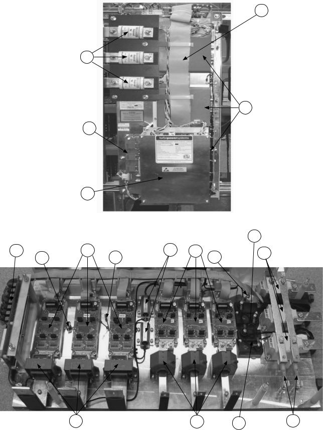
Controls
VFD ChassisDiagrams
16
1
4
3
2
|
|
|
|
|
15 |
5 |
6 |
14 |
7 |
13 |
8 |
12 |
13 |
|
|
|
11 |
10 |
15 |
9 |
WME0500SWater Cooled Chiller |
Rev. AC 09/15 |
RPL 7000176 / Page 14 |

Controls
VFD ChassisComponents & Compressor Wiring Harness
VFD ChassisComponents
Ref. |
Schem. |
|
|
|
|
No. |
Sym. |
Description |
|
Part No. |
Qty. 1 |
1 |
|
Fuse |
600A, 700V |
300047092 |
3 |
2 |
|
VFD Controller Assembly |
|
300048932 |
1 |
|
|
Backup Battery for VFD Controller |
334295801 |
1 |
|
3 |
|
Voltage Transducer Interface Board |
300048950 |
1 |
|
4 |
|
Link Capacitor |
1200uF, 700V |
300048939 |
3 |
5 |
|
Connector Interface |
|
300048934 |
1 |
6 |
Q4- 6 |
Steering Bridge IGBT Assy. |
|
300048937 |
3 |
7 |
Q1- 3 |
Chopper IGBT Assy. |
|
300048936 |
3 |
8 |
TDM1- 3 |
Diode Thyristor Module |
|
300049088 |
3 |
9 |
|
Fuse |
20A, 800V |
300048941 |
2 |
10 |
CT1- 3 |
Current Transducer |
|
300048942 |
3 |
11 |
CT4- 6 |
Current Transducer |
|
300048943 |
3 |
12 |
TS1 |
Thermal Switch |
|
300048945 |
1 |
13 |
TH1, 2 |
Thermistor |
|
300048944 |
2 |
14 |
R3, 4 |
Resistor |
2K2, 75W |
300049089 |
2 |
15 |
R1, 2 |
Resistor |
150R, 250W |
300048938 |
2 |
16 |
|
Wire Harness/Cable Kit 2 |
|
300055446 |
1 |
N/S |
L1- 3 |
Chopper Chokes/Inductors |
|
300048952 |
3 |
N/S |
|
Thyristor Driver Board |
|
300048933 |
1 |
N/S |
|
Snubber Board |
|
300048935 |
1 |
N/S |
|
Snubber Capacitors |
1uF, 1200V |
300048940 |
6 |
N/S |
D1 |
Diode |
|
300048951 |
1 |
N/S= Not Shown on Diagram.
1Quantity PER Chassis Assembly with the exception of chassis 300048873. VFD Chassis Assembly 300048873 has no Controller (Ref. #2).
2Kit contains ribbon cables and harnesses. Connections include: Q1-J10; Q2-J11; Q3-J12; Q4-J7; Q5-J8; Q6-J9; J1-J6; and J1-J14.
Compressor Wiring Harness
Compressor Wiring Harness 331795501 2 |
Compressor Wiring Harness 331795502 2 |
(12/11 & Earlier) |
(1/12 & Later) |
2 The Wiring Harnesses are available as complete assemblies only.
WME0500SWater Cooled Chiller |
Rev. AC 09/15 |
RPL 7000176 / Page 15 |

Controls
VFD Power Supply PlateDiagram
|
|
2 |
3 |
7 |
|
|
4 |
||
|
22 |
|
||
|
|
|
||
|
|
|
8 |
|
|
|
|
|
|
21 |
|
|
|
6 |
9
5
20
13
19
12 13 14
11
18
15
17 |
14 |
|
16
WME0500SWater Cooled Chiller |
Rev. AC 09/15 |
RPL 7000176 / Page 16 |
Controls
VFD Power Supply PlateComponents
Ref. |
Schem. |
|
|
|
|
|
No. |
Sym. |
Description |
|
|
Part No. |
Qty. |
2 |
|
PlatePartition |
|
Gray |
300047073 |
17 |
3 |
|
Terminal Block |
|
Gray |
300047074 |
36 |
4 |
|
Terminal BlockGround |
Green-Yellow |
300047075 |
9 |
|
5 |
|
BracketEnd, Snap on |
|
|
300047190 |
7 |
6 |
ELR |
RelayEarth Leakage |
|
|
300047078 |
1 |
7 |
CB1 |
Circuit BreakerPrimary |
|
8A |
300047079 |
1 |
8 |
CB2- 4 |
Circuit Breaker- 2 Fans & MCB trip |
2A |
300047080 |
3 |
|
9 |
|
SwitchFan Failure |
|
|
331578601 |
2 |
11 |
|
DC power supply |
+15 VDC 100 watts |
300047081 |
1 |
|
12 |
|
DC power supply |
15 VDC 25 watts |
300047082 |
1 |
|
13 |
|
DC power supply |
+24 VDC 77 watts |
300047083 |
2 |
|
14 |
|
DC power supply |
+24 VDC 100 watts |
300047084 |
2 |
|
15 |
|
DC power supply |
+12 VDC 72 watts |
300047085 |
1 |
|
16 |
|
DC Distribution Board |
|
|
300047086 |
1 |
17 |
PM |
MonitorVoltage, Power and Current |
|
300047087 |
1 |
|
18 |
TX2 |
Transformer |
480/240/120V |
500VA |
349939804 |
1 |
19 |
F110 |
Fuse holder |
|
|
300047088 |
7 |
20 |
F1-2, F8-10 |
Fuse |
|
|
300047089 |
2 |
21 |
F3- 5 |
Fuse |
|
|
300047090 |
3 |
22 |
F6-7 |
Fuse |
|
|
300046902 |
2 |
WME0500SWater Cooled Chiller |
Rev. AC 09/15 |
RPL 7000176 / Page 17 |
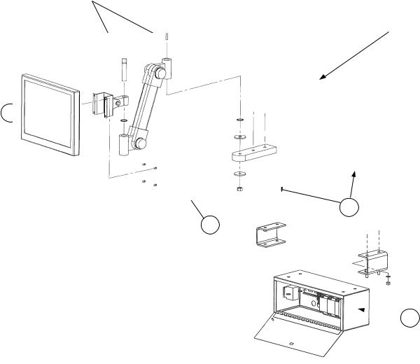
Controls
OITSOperator Interface Touch Screen and Rapid Restore
Swivel Pins 1 |
|
Swivel Bracket 1 |
Main Control Box |
15
18
 20
20
Ref.No. |
Description |
Part No. |
Qty. |
|
|
|
|
15 |
Monitor15" LCD Touchscreen 2 |
|
|
|
9/2010 and Before, Beige |
330276501 |
1 |
|
10/2010 and Later, Black |
330276502 |
1 |
16 |
LCD Support Arm Assembly 2 |
|
|
|
9/2010 and Before, Beige |
330815401 |
1 |
|
10/2010 and Later, Black |
330815411 |
1 |
18 |
OITS/Unit Control Box Support Block |
330406501 |
2 |
|
|
|
|
20 |
Rapid Restore Kit (includes mounting brackets and hardware) |
331585160 |
1 |
1These parts are included with the LCD Support Arm Assembly. The mounting hardware (screws, washers and nuts) are also included and are not available separately.
2In 9/2010 the color of the LCD Touchscreen and LCD support arm was changed from Beige to Black. Form, fit, and function are identical and parts can be substituted for each other.
WME0500SWater Cooled Chiller |
Rev. AC 09/15 |
RPL 7000176 / Page 18 |
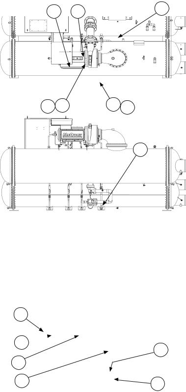
Control Sensors
087 (Rev. AAA) Impeller Units Sensor Location Diagrams
S07
S14
Top View
S13 S12 |
S15 |
S10 S11
Front View
Evaporator
Condenser
S09
End View
|
|
S06 |
S04 |
In |
Out |
S01 |
|
Out |
|
|
|
S02 |
|
S05 |
S08 |
|
In |
WME0500SWater Cooled Chiller |
Rev. AC 09/15 |
RPL 7000176 / Page 19 |
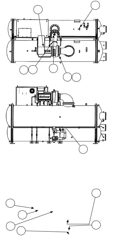
Control Sensors
092 (Rev. AAB) Impeller Units Sensor Location Diagrams
S14 |
S15 |
S07 |
|
Top View
S13 S12 |
S10 S11 |
Front View
S09
Evaporator
Condenser
End View
S04
In Out
S01
Out |
S05 |
S02 |
In |
|
|
S06 |
S08 |
|
WME0500SWater Cooled Chiller |
Rev. AC 09/15 |
RPL 7000176 / Page 20 |
Control Sensors
Components
Ref. |
Description |
Part |
Qty. |
No. |
|
Number |
|
S01 |
SensorEvaporator Entering Water Temperature |
073007203 |
1 |
S02 |
SensorEvaporator Leaving Water Temperature |
073007203 |
1 |
S04 |
SwitchEvaporator Entering Flow |
331796201 |
1 |
N/S |
CableEvaporator Entering Flow Switch (5 Meter Lg.) |
330571402 |
1 |
S05 |
SensorCondenser Entering Water Temperature |
073007203 |
1 |
S06 |
SensorCondenser Leaving Water Temperature |
073007203 |
1 |
S07 |
SensorCondenser Refrigerant Pressure |
071568621 |
1 |
S08 |
SwitchCondenser Entering Flow |
331796201 |
1 |
N/S |
CableCondenser Entering Flow Switch (5 Meter Lg.) |
330571402 |
1 |
S09 |
SensorLiquid Line Temperature |
073007203 |
1 |
S10 |
SensorCompressor Suction Temperature |
3317952011, 2 |
1 |
S11 |
SensorCompressor Suction Pressure |
071568521 |
1 |
N/S |
CableCompressor Suction Pressure Sensor |
331796801 |
1 |
S12 |
SensorCompressor Discharge Temperature |
3317952011, 2 |
1 |
S13 |
SensorCompressor Discharge Pressure |
0715686212 |
1 |
S14 |
SensorMotor Gap Temperature |
3317952052 |
1 |
S15 |
SwitchHigh Pressure |
074796301 |
1 |
N/S= Not Shown on Diagram.
1Early production units used sensor 331795205. This sensor is 6.0" OAL. P/N 331795201 is 4.38" OAL. Confirm which sensor is required before ordering.
2The Cable for this Sensor is part of the Compressor Wiring Harness and is NOT available separately. Refer to the Compressor Wiring Harness section for harness p/ns.
WME0500SWater Cooled Chiller |
Rev. AC 09/15 |
RPL 7000176 / Page 21 |
 Loading...