


GENERAL ELECTRIC PGSS5PJXSS, PGSS5NFXSS, PGCS1PJXSS, PFSS5PJXSS, PFSS5NJXSS User Manual
...Refrigerators
Bottom Freezer
GEAppliances.com
Safety Instructions . . . . . . . . . . .2, 3
Operating Instructions
Additional Features . . . . . . . . . . . . . . . . .8
Automatic Icemaker . . . . . . . . . . . . . . .11
Care and Cleaning . . . . . . . . . . . . .12–13
Controls . . . . . . . . . . . . . . . . . . . . . . . . . .4–5
Crispers and Pans . . . . . . . . . . . . . . . . . . .9
Freezer . . . . . . . . . . . . . . . . . . . . . . . . . . . .10
Replacing the Light Bulbs . . . . . . . . . .14
Shelves and Bins . . . . . . . . . . . . . . . . . .7, 8
Water Dispenser . . . . . . . . . . . . . . . . . . .11
Water Filter . . . . . . . . . . . . . . . . . . . . . . . . .6
Installation Instructions
Installing the Anti-Tip
Floor Bracket . . . . . . . . . . . . . . . . . .18–19 Installing the Refrigerator . . . . . . .20–24 Installing the Water Line . . . . . . . .33–35 Preparing to Install
the Refrigerator . . . . . . . . . . . . . . . . . . . .17 Removing and Replacing the
Freezer Drawer . . . . . . . . . . . . . . . . .25, 26 Reversing the Door Swing
(Single Door Refrigerator
Models only) . . . . . . . . . . . . . . . . . . .27–29 Removing and Replacing
the Doors (Double Door
Refrigerator Models only) . . . . . . .30–32 Trim Kits and Decorator Panels . . . .15–16
Troubleshooting Tips . . . . . .36–40
Normal Operating Sounds . . . . . . . . . .36
Consumer Support
Consumer Support . . . . . . . .Back Cover Performance Data Sheet . . . . . . . . . . .43 State of California Water
Treatment Device Certificate . . . . . . .44 Warranty for Canadian
Customers . . . . . . . . . . . . . . . . . . . . . . . . .42 Warranty for U.S. Customers . . . . . . .41
Write the model and serial numbers here:
Model # ____________________
Serial #______________________
Find these numbers on a label
on the right side, near the top of the refrigerator compartment.
Owner’s Manual and
Installation Instructions
Models 21 and 25
Congélateur inférieur
Réfrigérateurs
Manuel d’utilisation et d’installation
La section française commence à la page 45
Congelador inferior
Refrigeradores
Manual del propietario y instalación
La sección en español empieza en la página 89
200D9366P008 49-60583 01-09 JR
Operating Instructions Safety Instructions
Installation |
Instructions |
Consumer Support Troubleshooting Tips
IMPORTANT SAFETY INFORMATION.
READ ALL INSTRUCTIONSBEFORE USING.
 WARNING!
Use this appliance only for its intended purpose as described in this Owner’s Manual.
SAFETY PRECAUTIONS
When using electrical appliances, basic safetyprecautions should be followed, including the following:
■This refrigerator must be properly installed and located in accordance withthe Installation Instructions before it is used.
■Do not allowchildren to climb, standor hang on the shelves in the refrigerator.Theycould damagethe refrigerator and seriously injure themselves.
■Do not touch the cold surfacesin the freezer compartment when handsare dampor wet. Skin may stick to these extremelycold surfaces.
■Do not store or use gasolineor other flammable vapors and liquidsin the vicinity of this or any other appliance.
■Keep fingers out of the “pinch point”areas; clearances between the doors and between the doors and cabinet are necessarily small.Be careful closing doors when children are in the area.
■In refrigerators with automatic icemakers, avoid contact with the moving parts of the ejector mechanism, or with the heating element that releases the cubes. Do not place fingers or hands on the automatic icemaking mechanismwhile the refrigerator is plugged in.
■Unplug the refrigerator beforecleaning and making repairs.
NOTE: We strongly recommend that any servicing be performed by a qualified individual.
■Setting either or both controls to 0 (off) does not remove power to the light circuit.
■Do not refreeze frozen foods which have thawed completely.
 DANGER! RISK OF CHILD ENTRAPMENT
PROPER DISPOSAL OF THE REFRIGERATOR
Childentrapment and suffocation are not problems of Refrigerants the past. Junked or abandoned refrigeratorsare still
dangerous…even if they willsit for “just a few days.” If |
All refrigeration products contain refrigerants, |
|
which under federal law must be removed prior to |
||
you are getting rid of your old refrigerator,please |
||
product disposal. If you are getting rid of an old |
||
followthe instructions below to help prevent |
||
refrigeration product, check with the company |
||
accidents. |
||
handling the disposal about what to do. |
||
Before You Throw Away Your Old |
||
|
||
Refrigerator or Freezer: |
|
■Take off the doors.
■Leave the shelvesin placeso that children may not easilyclimbinside.
USE OF EXTENSION CORDS
Because of potential safety hazards under certainconditions, we stronglyrecommendagainst the use of an extension cord.
However, if you must use an extension cord, it is absolutely necessary that it be a UL-listed (in the UnitedStates) or a CSA certified (in Canada),3-wire groundingtype appliance extension cord having a groundingtypeplug
2and outlet and that the electricalratingof the cord be 15 amperes (minimum) and 120 volts.
GEAppliances.com
 WARNING!
HOW TO CONNECT ELECTRICITY
Do not, under any circumstances, cut or remove the third(ground) prong from the powercord. For personal safety, this appliance must be properly grounded.
The power cord of this applianceis equippedwitha 3- prong (grounding)plug which mates with a standard 3-prong (grounding) walloutlet to minimize the possibilityof electric shock hazard from this appliance.
Have the wall outlet and circuit checked by a qualified electricianto makesure the outlet is properly grounded.
Where a standard 2-prong walloutlet is encountered, it is your personal responsibility and obligation to have it replacedwith a properly grounded 3-prong wall outlet.
The refrigerator should always be pluggedinto its own individualelectricaloutlet which has a voltage ratingthatmatches the rating plate.
This provides the best performance and also prevents overloading housewiring circuits which could cause a fire hazard from overheated wires.
Never unplug your refrigerator by pulling on the power cord. Always grip plug firmly and pull straight out from the outlet.
Repair or replace immediately all power cords that have become frayed or otherwise damaged. Do not use a cord that shows cracks or abrasion damage along its length or at either end.
When moving the refrigerator away from the wall, be careful not to roll over or damage the power cord.
READ AND FOLLOW THIS SAFETY INFORMATION CAREFULLY.
SAVE THESE INSTRUCTIONS
3
Instructions Operating Instructions Safety
Instructions |
Installation |
Support Consumer Tips Troubleshooting

Operating Instructions Safety Instructions
Installation |
Instructions |
Consumer Support Troubleshooting Tips
About the controls with temperature settings.
(on some models)
(on some models)
NOTE: The refrigerator is shippedwith protective film covering the temperaturecontrols. If this film was not removed duringinstallation, remove it now.
The temperature controls are preset in the factory at 37°F for the refrigerator compartment and 0°F for the freezer compartment. Allow 24 hours for the temperature to stabilize to the preset recommended settings.
The temperature controls can display both the SET temperature as well as the actual temperature in the refrigerator and freezer. The actual temperature may vary slightly from the SET temperature based on usage and operating environment.
Setting either or both controls to OFF stops cooling in both the freezer and refrigerator compartments, but does not shut off electrical power to the refrigerator.
|
Changing the Temperature |
|
|
For Controls-on-the-DoorModels: |
|
|
To changethe temperature,press and release the |
|
|
WARMER or COLDER pad. The ACTUALTEMP light |
|
|
willcome on and the displaywillshow the actual |
|
|
temperature. To change the temperature, tap either |
|
|
the WARMER or COLDER pad untilthe desired |
|
|
temperature is displayed. |
|
|
For ControlsInside the Refrigerator: |
|
|
Openingthe door displaysthe actualtemperature. To |
|
|
changethe temperature, press eitherthe WARMER or |
|
|
COLDER touch padsuntil the desired temperature is |
|
|
displayed. |
|
|
Once the desiredtemperature has beenset, |
|
|
the temperature displaywillreturnto the actual |
|
4 |
refrigerator and freezertemperatures after 5 seconds. |
|
Several adjustments may be required. |
||
|
Each time you adjust controls, allow 24 hoursfor the refrigerator to reach the temperature you have set.
To turnthe cooling system off, tap the WARMER pad for either the refrigerator or the freezer until the display shows OFF. To turnthe unitback on, press the COLDER pad for either the refrigerator or freezer. Then press the COLDER pad again and it willgo to the preset points of 0°F for the freezer and 37°F for the refrigerator. Setting either or both controls
to OFF stops cooling in both the freezer and refrigerator compartments, but does not shut off electrical power to the refrigerator.

About TurboCool.™ (on some models) |
GEAppliances.com |
(on some models)
(on some models)
How It Works
TurboCool rapidlycools the refrigerator compartment in order to more quickly cool foods. Use TurboCool when adding a largeamount of food to the refrigerator
compartment, putting awayfoods after they havebeen sitting out at room temperature or when putting awaywarmleftovers.It can alsobe used if the refrigerator has been without power for an extended period.
Once activated, the compressor will turn on immediately and the fans willcycleon and off at high speedas needed for eighthours. The compressor willcontinue to run until the refrigerator compartment cools to approximately 34°F (1°C), thenit will cycle on and off to maintain thissetting. After 8 hours, or if TurboCool is pressed again, the refrigerator compartment will returnto
the original setting.
How to Use
Press TurboCool. The refrigerator temperature display will show .
.
After TurboCool is complete, the refrigerator compartment will return to the original setting.
NOTES: The refrigerator temperature cannot be changed during TurboCool.
The freezer temperature is not affected during TurboCool.
When opening the refrigerator door during TurboCool, the fans
will continue to run if they have cycled on.
About Door Alarm (on some models)
The door alarm willsound if any door is open for more than 2 minutes. The beepingstops when you closethe door.
(on some models)
(on some models)
About Energy Saver (on some models)
This product is equippedwithan Energy Saverfeature. The refrigeratoris shipped with the Energy Saverfeature enabled.
Over time, moisture can form on the front
surface of the refrigerator cabinet and cause (on some models) rust. If moisture does appearon the front
surface of the refrigerator cabinet, turn off the Energy Saverfeature by pressing and releasingthe ENERGY SAVER pad on the control panel.
(on some models)
5
Instructions Operating Instructions Safety
Instructions |
Installation |
Support Consumer Tips Troubleshooting

Operating Instructions Safety Instructions
Installation |
Instructions |
Consumer Support Troubleshooting Tips
About the water filter. (on some models)
Cartridge 
Holder
Cartridge 
Holder
(on some models)
(on some models)
Water Filter Cartridge
The water filter cartridgeis located in the back upperright corner of the refrigerator compartment.
When to Replace the Filter
There is a replacement indicator light for the water filter cartridge on the temperature display. This light will turn orange to tell you that you need to replace the filter soon. The filter cartridgeshould be replaced when the replacement indicator lightturns red or if the flow of water to the dispenser or icemaker decreases.
Installing the Filter Cartridge
If you are replacing the cartridge, first remove the old one by slowly turning it to the left. DO NOTpull down on the cartridge. A small amount of water may dripdown.
 CAUTION: If air has been trapped in the system, the filter cartridge may be ejected as it is removed.Use caution when removing.
Remove the protective foil fromthe end of the cartridge.
Fillthe replacement cartridge with water from the tap to allow for better flow from the dispenser immediately after installation.
Lining up the arrow on the cartridge and the cartridge holder,slowly rotate the cartridge clockwise untilit stops. When the cartridge is properlyinstalled, you will feel it “click” as it locks into place. Do not overtighten.
Run water from the dispenser for
3 minutes (about 11⁄ 2 gallons)to clear the system and preventsputtering. See To Use the Dispenser section.
Press and hold the RESETWATER FILTER pad for 3 seconds.
NOTE: A newly-installed waterfilter cartridge may causewater to spurt from the dispenser.
Filter Bypass Plug
Youmustuse the filter bypass plug when a replacement filter cartridge is not available. The icemaker will not operate without the filter or filter bypass plug.
Replacement Filters:
To orderadditional filter cartridges in the United States, visit our Website,
GEAppliances.com, or call GE Parts and Accessories, 800.626.2002.
Filter Model MWF
Customers in Canada should consult the yellow pages for the nearest Mabe Service Center.
6

About the shelvesand bins. |
GEAppliances.com |
Not all features are on all models.
Rearranging the Shelves
Shelves in the refrigerator compartment are adjustable.
RefrigeratorCompartment
To remove:
 Remove all items from the shelf.
 Tiltthe shelf up at the front.
Liftthe shelf up at the backand bring the
shelf out.
Some models have wire shelves that can be adjusted in the same manner.
To replace:
While tilting the shelf up, insert the top hook at the backof the shelf in a slot on the track.
Lower the front of the shelf untilthe bottom of the shelf locks into place.
Spillproof Shelves (on some models)
Spillproof shelveshave special edgesto help prevent spillsfrom dripping to lower shelves. To remove or replace the shelves,see
Rearranging the Shelves.
Slide-Out Spillproof Shelf (on some models)
The slide-out spillproof shelfallows you to reach items stored behind others. The
special edges are designed to help prevent spillsfrom dripping to lower shelves.
To remove:
 Remove all items from shelf.
 Slidethe shelf out untilit stops.
To replace:
Place the rear shelf tabs just in front of the central notches on the shelf frame.
 Slide the shelf in until the central tabs are slightly behind the front bar.
Lower the shelf into place until it is horizontal and slide the shelf in.
Lift the front edge of the shelf until the |
Make sure that the shelf sits flat after |
|
central tabsare above the front bar. |
reinstallation and doesn’t move freely from |
|
Continue pullingthe shelf forward |
side to side. |
|
Make sure you push the shelves all the way in |
||
until it can be removed. |
||
|
before you close the door. |
7
Instructions Operating Instructions Safety
Instructions |
Installation |
Support Consumer Tips Troubleshooting
Operating Instructions Safety Instructions
Installation |
Instructions |
Consumer Support Troubleshooting Tips
About the shelves and bins.
Adjustable Bins on the Door
Adjustablebins can easily be carried from refrigerator to work area.
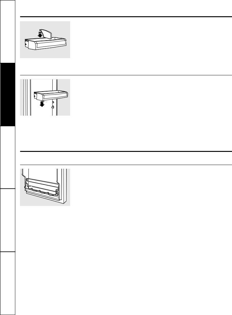
To remove: Lift bin straightup, then pull out.
To replace or relocate: Slidein the bin just above the molded door supports, and push down. The bin will lock in place.
The snugger helps prevent tipping, spilling or sliding of small items stored on the door shelf. Grip the finger hold near the rear of the snugger and move it to fit your needs.
Non-Adjustable Bins on the Door
To remove: Lift the bin straightup, then pull out.
To replace: Engage the bin in the molded supports on the door and pushdown.
It willlock in place.
About the additionalfeatures.
Not all features are on all models.
Non-Adjustable Beverage Rack
To remove: Lift the rackstraight up, then pull out.
To replace: Engage the rackin the molded supports on the door and pushdown.
It willlock in place.
8

About the crispers and pans. |
GEAppliances.com |
Not all features are on all models.
Fruit and Vegetable Crisper
Excess water that may accumulatein the bottom of the drawers or underthe drawers should be wipeddry.
Adjustable Humidity Crisper (on some models)
Slidethe control all the way to the |
Slide the controlall the way to the LOW |
HIGH setting to provide high humidity |
setting to provide lower humidity levels |
recommended for most vegetables. |
recommended for most fruits. |
Adjustable Temperature Deli Pan (on some models)
Slidethe control all the way to the leftfor the coldest temperature.
How to Remove and Replace the Deli Pan
To remove: |
To replace: |
 Remove the fruit and vegetable drawers.
  Pull the drawer out to the stop position.
Swing Locks |
Lift the lid to access the 4 swing locks. |
 Rotate all four swing locksto the unlock position.
 Liftthe front of the drawerup and out.
 Make sure all fourswing locks are in the unlock position.
 Place the sides of the drawer into the drawer supports, making sure the swing locks fit on the drawer slots.
 Lock all fourswing locks by rotating them to the lock position.
 Lower the lid and slide in the drawer.
  Replace the fruit and vegetable drawers.
9
Instructions Operating Instructions Safety
Instructions |
Installation |
Support Consumer Tips Troubleshooting
Operating Instructions Safety Instructions
Installation |
Instructions |
Consumer Support Troubleshooting Tips
About the freezer.
Not all features are on all models.
Freezer Shelves and Baskets
 A shelf above the ice storage bin
 A half-width basket
 A shallow full-width basket
 A deepfull-width basket
Appearance and features may vary
Basket Removal
To remove the deep full-width basket on freezer drawer models:
 Open the freezer draweruntil it stops.
 The freezerbasket restson the inside tabson the drawer slides.
Appearance may vary |
Lift the basket so that all 4 tabs are out of |
|
the slidebracket. |
||
|
Tab
 Tilt the basket and lift out of the drawer.
 Make sure the plastic sleeves remain attached to the 4 tabs on the slide brackets.
When replacing the deep full-width basket:
Tilt the basket back and lower it down into the drawer.Rotate the basket to a horizontal position and press it down into the 4 alignment tabs.
NOTE: Always be sure that all 4 basket tabs are engaged in the slide brackets before sliding back into the freezer.
To remove the half-width basket:
 Pull the basket out to the stop location.
 Lift the basket up at the front to release it from the slides.
 Lift the back up and out of the slide.
When replacing the basket, make surethat the wire tabs and wire hooks on the sides of the basket go into the slots in the top
of the upper basket slides.
NOTE: Always be sure to fully close this basket.
Appearance may vary
To remove the shallow full-width basket:
Pull the basket out to the stop location. |
Lift the basket up and out. |
Lift the front up and over the stop |
|
location. |
|
Appearance may vary
10
About the automatic icemaker. |
GEAppliances.com |
A newly installed refrigerator may take 12 to 24 hours to begin making ice.
Power |
|
Automatic Icemaker (on some models) |
Switch |
|
Icemaker The icemaker willproduce seven cubesper cycle— |
|
|
|
|
|
approximately 100–130cubes in a 24-hour period, |
|
|
depending on freezer compartment temperature, |
|
|
room temperature, number of door openings and |
|
|
other use conditions. |
|
|
See belowfor how to accessice and reachthe |
|
|
power switch. |
Green |
FeelerArm |
If the refrigeratoris operatedbeforethe water |
Power Light |
connectionis made to the icemaker,set the power |
|
|
|
|
|
|
switch in the O (off) position. |
|
|
When therefrigeratorhas been connected tothe |
|
|
watersupply, setthepower switchto the l (on) |
|
|
position. The icemakerpowerlightwill turngreen |
|
|
when the freezerlight switch ispressedin or when |
|
|
thefreezer door isclosed. |
|
|
Theicemaker will fill withwaterwhen it cools to |
|
|
15°F(–10°C). A newlyinstalledrefrigerator maytake |
|
|
12to24hourstobeginmaking icecubes. |
You willheara buzzing soundeachtime the icemakerfillswithwater.
Throwawaythe first few batchesof ice to allow the waterlineto clear.
Be surenothing interfereswith the sweep of the feelerarm.
Whenthe bin fills to the levelof the feelerarm,the icemaker will stopproducingice. It is normalfor severalcubesto be joinedtogether.
If ice is not usedfrequently, old ice cubeswill become cloudy, tastestale and shrink.
NOTE: In homeswith lower-than-averagewater pressure, you may hearthe icemakercycle multiple timeswhen makingone batch of ice.
NOTE: Set the powerswitchto the O (off) positionif the water supplyis shutoff.
Shelf
Ice Bin
To reach the power switch.
Accessing Ice and Reaching
the Power Switch
To reachthe icemaker powerswitch,pullthe shelf abovethe ice bin straightout. Alwaysbe sure to replace the shelf.
To access ice,simply pullthe bin forward.
Shelf
Ice Bin
To access ice.
Icemaker Accessory Kit
If yourrefrigerator didnotcomealreadyequipped |
Checkthe backof the refrigeratorfor the specific |
withan automatic icemaker,anicemakeraccessory |
icemaker kit neededfor yourmodel. |
kitis available atextracost. |
|
To Use the External Dispenser (on some models)
DispenserCradle
Spill Shelf
Pressthe glass gently against the top of the dispensercradle.
The spillshelfisnot self-draining. To reduce water spotting,theshelfshouldbecleaned regularly.
If no water is dispensedwhen the refrigeratoris first installed, there may be air in the waterline system. Press the dispenserarm for at leasttwo minutesto remove trapped air from the waterline and to fill the water system. To flushout impurities in the water line,throw awaythe first six glassfuls of water.
Locking the Dispenser
Pressthe LOCK pad for 3 secondsto lock
the dispenserand controlpanel. To unlock, press and holdthe pad againfor 3 seconds.
Door Alarm
Tosetthe alarm, press theDOOR ALARM pad.The indicatorlight will illuminate. This alarm willsoundif either doorisopen formore than 2 minutes.The beeping stops when youclose the door.
To Use the Internal Dispenser (on some models)
The water dispenser is located on the left wall inside the refrigerator compartment.
 To dispense water:
 Hold the glass againsttherecess.
 Push the water dispenser button.
Hold the glass underneaththe dispenser for 2–3 seconds after releasingthe dispenser button. Water may continue to dispense after the button is released.
Ifno water is dispensedwhen the refrigerator isfirst installed,there may be air in thewaterline system. Press the dispenser button for at least 2 minutes to remove trappedair fromthe waterline and to fillthe watersystem.Duringthis process, the dispenser noise maybe loudas theair is purged from thewater line system. To flushout impurities in the water line, throw away the first 6 glassfuls of water.
NOTE: To avoid water deposits, the dispenser should be cleaned periodically by wiping with 11 a clean cloth or sponge.
Instructions Operating Instructions Safety
Instructions |
Installation |
Support Consumer Tips Troubleshooting

Operating Instructions Safety Instructions
Installation |
Instructions |
Consumer Support Troubleshooting Tips
Care and cleaningof the refrigerator.
Cleaning the Outside
The door handles and trim. Clean with a cloth dampened with soapywater.Dry with a soft cloth. Do not use wax on the door handlesand trim.
Keep the outside clean.Wipe with a clean cloth lightly dampened with kitchen appliance wax or mildliquid dish detergent. Dry and polish with a clean,softcloth.
Do not wipe the refrigerator with a soiled dish cloth or wet towel. These may leave a residue that can erode the paint. Do not use scouring pads, powdered cleaners, bleach or cleaners containing bleach because these products can scratch and weaken the paint finish.
The stainless steel panels and door handles.
Stainless steel (on some models) can be cleaned with a commercially available stainless steel cleaner. A spray-on stainless steel cleaner works best.
Do not use appliance wax or polish on the stainless steel.
Silver-plated plastic parts. Wash parts with soapor other mild detergents. Wipe clean with a sponge, damp cloth or paper towel.
Do not scrub with steel-wool pads or other abrasive cleaners.
Cleaning the Inside
To help prevent odors, leavean open box of baking soda in the refrigeratorand freezer compartments.
Unplug the refrigerator before cleaning. If this is not practical, wring excess moisture out
of sponge or cloth when cleaning around switches, lights or controls.
Use an appliance wax polish on the inside surface between the doors.
Use warm water and bakingsoda solution— about a tablespoon(15 ml) of baking soda to a quart (1 liter) of water.Thisboth cleans and neutralizes odors.Rinse and wipe dry.
After cleaning the door gaskets, apply a thin layer of petroleum jelly to the door gaskets at the hinge side. This helps keep the gaskets fromsticking and bending out of shape.
Avoid cleaning cold glass shelves with hot water because the extreme temperature difference may cause them to break. Handle glass shelves carefully. Bumping tempered glass can cause it to shatter.
Do not wash any plastic refrigerator parts in the dishwasher.
Silver-accented plastic parts. Wash parts with soapy water. Wipe clean with a sponge, damp cloth or paper towel.
Do not scrub with steel-wool pads or other abrasive cleaners.
12

GEAppliances.com
Behind the Refrigerator
Be careful when moving the refrigerator awayfrom the wall.All typesof floor coveringscan be damaged,particularly cushioned coverings and those with embossed surfaces.
Raisethe levelinglegslocatedat the bottom front of the refrigerator.
Pull the refrigerator straightout and return it to position by pushing it straightin. Moving the refrigerator in a side direction may result in damageto the floor covering or refrigerator.
Lower the leveling legs until they touch the floor.
When pushing the refrigerator back, make sure you don’t roll over the power cord or icemaker supply line (on some models) and ensure the anti-tip bracket is engaged (if equipped).
Preparing for Vacation
For long vacations or absences, remove food and unplugthe refrigerator.Clean the interior witha baking soda solution of one tablespoon (15 ml) of baking soda to one quart (1 liter) of water.Leavethe doors open.
Set the icemakerpowerswitchto the O (off) position and shut off the water supply to the refrigerator.
If the temperature can drop below freezing, have a qualified servicer drain the water supply system (on some models) to prevent serious property damage due to flooding.
Preparing to Move
Secure all loose items suchas base grille, shelvesand drawers by taping them securelyin place to prevent damage.
When usinga hand truckto move the refrigerator, do not rest the front or back of the refrigerator against the handtruck. This could damagethe refrigerator.Handle only from the sides of the refrigerator.
Be sure the refrigerator stays in an upright position during moving.
13
Instructions Operating Instructions Safety
Instructions |
Installation |
Support Consumer Tips Troubleshooting
Operating Instructions Safety Instructions
Installation |
Instructions |
Consumer Support Troubleshooting Tips
Replacing the lightbulbs.
Turning the control to the 0 (off) position does not remove power to the light circuit.
Refrigerator Lights (on some models)
 CAUTION: Light bulbs may be hot.
 Unplug the refrigerator.
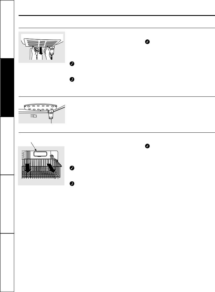
To remove the light shield,grasp the shield at the back and pull out to release the tabs at the back.
Rotate the shield downand then forward to release the tabs at the front of the shield.
After replacing with an appliance bulb of the sameor lower wattage, replace the shield.
 Plug the refrigerator back in.
NOTE: Appliance bulbs may be ordered from GE Parts and Accessories, 800.626.2002.
LED Refrigerator Lights (on some models)
An authorizedtechnicianwill need to replace the LED light.
Light |
Freezer Light |
|
Shield |
||
|
Appearance may vary
 CAUTION: Light bulbs may be hot.
 Unplug the refrigerator.
Remove the freezer basket for access. The bulbis located at the rear of the freezer inside a light shield.
To remove, grasp the shield at the top and pullout to release the tabs at the bottom.
After replacing with an appliance bulb of the sameor lower wattage, replace the shield and freezer basket.
 Plug the refrigerator back in.
14

Trim kits and decoratorpanels. |
GEAppliances.com |
For panel-required models
Readthese instructions completely and carefully.
Before You Begin
Some models are equipped with trim kits that allow you to install door panels. You can order pre-cut black or white decorator panels from GE Parts and Accessories, 800.626.2002, or you can add wood panels to match your kitchen cabinets.
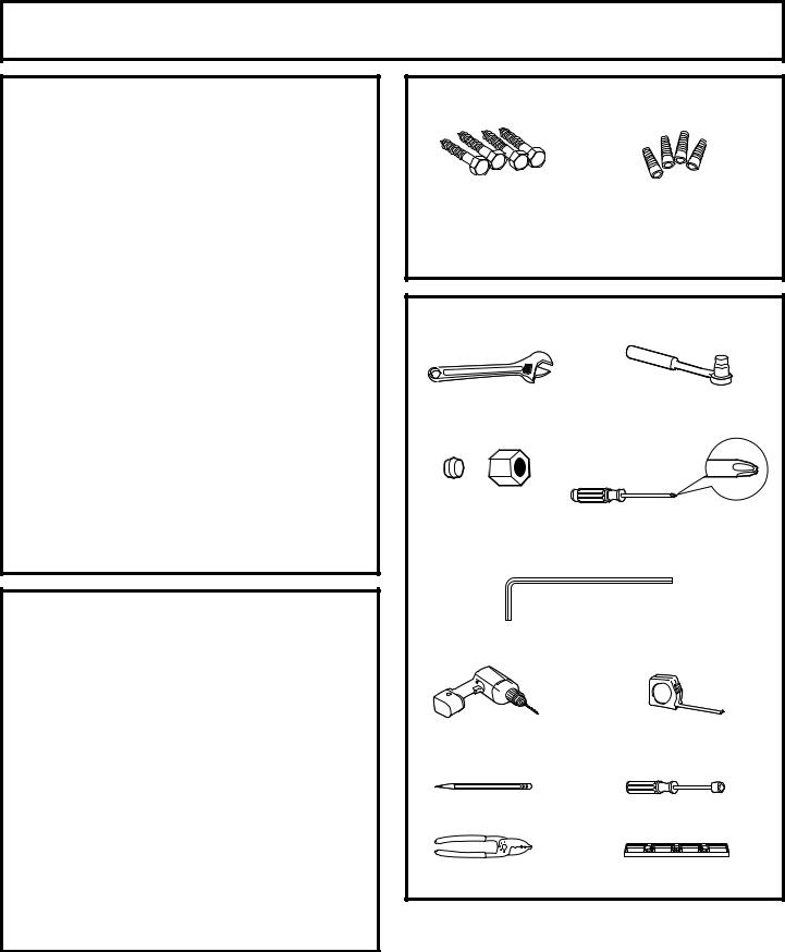
Panels less than 1/4″ (6 mm) thick
When installing wood panels less than 1/4″ (6 mm) thick, you need to create a fillerpanel, suchas 1/8″ cardboard, thatwillfit between the face of the door and the wood panel. If you are installingthe pre-cut decoratorpanels,pre-cut filler panels are included in the kit. The combined thicknessof the decorator or wood panel and the filler panel should be 11/32″ (8.7 mm) with the panel itself being no larger than 1/4″ (6 mm).
Panels1/4″ thick or less
1/4″ max
The handleand the top and bottom trimstand in front of the surface of the door,whichrequiresthat the filler be smaller in length and width than the panel. Use the guidelines below and tape the filler onto the back of the panel.
Left Fresh Food Door |
Right Fresh Food Door |
Filler |
Filler |
|
3/4″ (19 mm) |
|
3/4″ (19 mm) |
|
2 1/2″ (63.5 mm) |
Panel |
Panel |
3/4″ (19 mm)
 3/4″ (19 mm) 2 1/2″ (63.5 mm)
Freezer Door
Filler
3/4″ (19 mm)
2 1/2″ (63.5 mm)
Panel |
15 |
Instructions Operating Instructions Safety
Instructions |
Installation |
|
|
Support Consumer Tips Troubleshooting
Operating Instructions Safety Instructions
Installation |
Instructions |
|
|
Consumer Support Troubleshooting Tips
Trim kits and decoratorpanels.
3/4″ (19 mm) or Raised Panel
A raised panel design screwed or glued to a 1/4″ (6 mm) thick backing, or a 3/4″ (19 mm) routed board can be used. The raised portionof the panelmust be fabricated to permit clearances of at least 2″ (5.1cm) from the handlesidefor fingertip clearance.
Panels thicker than1/4″ (6 mm), up to 3/4″ (19 mm) max.,will require that the outer5/16″ (8 mm) of panel perimeterbe no thicker than1/4″ (6 mm).
Weight limitations for custom panels:
Fresh Food 10 lbs. (4.5 kg) max. for each door
Freezer Door 18 lbs. (8 kg) max.
Panelsthickerthan 1/4″ (6 mm) |
1/4″ (6 mm) |
|
Thick Backing |
||
|
||
5/16″ (8 mm) |
|
|
2″ (5.1 cm) |
|
|
Clearance |
|
|
HandleSide |
|
|
1/4″ (6 mm) max |
3/4″ |
|
Appearance |
(19 mm) |
|
Refrigerator |
||
Panel |
||
3/4″ (19 mm) |
Door |
|
|
Dimensions for Custom Wood Panels
|
|
|
|
1/8″ |
|
|
|
Left Fresh Food Door |
Right Fresh Food Door |
1/8″ |
|
(3 mm) |
(3 mm) |
||
|
|
|
|
1/4″ |
|
(6 mm) |
|
5/16″ (8 mm) |
2″ (51 mm) |
minimum at |
minimum at |
1/4″ (6 mm) |
1/4″ (6 mm) |
thickness |
thickness |
Top, left and |
Handle side |
bottom |
|
|
38 15/16″ |
Raised portion |
(98.9 cm) |
|
|
of panel |
|
1/8″ |
|
(3 mm) |
16 29/32″ (42.9 cm) |
|
|
1/4″ |
|
|
(6 mm) |
|
2″ (51 mm) |
5/16″ (8 mm) |
|
minimum at |
minimum at |
|
1/4″ (6 mm) |
1/4″ (6 mm) |
|
thickness |
thickness |
|
Handle side |
Top, right and |
|
bottom |
||
|
||
Raised portion |
38 15/16″ |
|
(98.9 cm) |
||
of panel |
|
|
|
1/8″ |
|
|
(3 mm) |
|
|
16 29/32″ (42.9 cm) |
|
|
|
|
|
|
|
|
|
|
|
|
|
|
|
|
|
|
|
|
|
|
|
|
|
|
|
|
|
|
|
|
|
|
|
|
|
|
|
|
|
|
|
|
|
|
|
|
|
|
|
|
|
|
|
|
|
|
|
|
|
|
|
|
|
|
|
|
|
|
|
|
|
|
|
|
|
|
|
|
|
|
|
|
|
|
|
|
|
|
|
|
|
|
|
|
|
|
|
|
|
|
|
|
|
|
|
|
|
|
|
|
|
|
|
|
|
|
|
|
|
|
|
1/4″ |
|
|
|
|
|
|
|
|
|
|
|
|
|
|
|
|
|
|
|
|
|
|
|
|
|
|
|
|
|
|
|
|
|
|
|
|
|
|
|
|
1/4″ |
|
|
|
|
||
|
|
|
|
|
|
|
|
|
|
|
|
|
|
|
|
|
|
|
|
|
|
|
|
|
|
|
|
|
|
|
|
|
|
|
|
|
|
|
|
|
|
|
|
|
|
|
||||||||||
|
|
|
|
|
|
|
|
|
(6 mm) |
2″ (51 mm) minimum at |
|
|
|
|
|
|
|
|
|
|
|
|
|
|
|
|
|
|
(6 mm) |
|
|
|||||||||||||||||||||||||
|
|
|
|
|
|
|
|
|
|
|
FreezerDoor |
|
||||||||||||||||||||||||||||||||||||||||||||
|
|
|
|
|
|
|
|
|
|
|
|
|||||||||||||||||||||||||||||||||||||||||||||
|
|
|
|
|
|
|
|
|
|
|
1/4″ (6 mm) thickness |
|
||||||||||||||||||||||||||||||||||||||||||||
|
|
|
|
|
|
|
|
|
|
|
Handle side |
|
|
|
|
|
|
|
|
|
|
|
|
|
|
|
|
|
|
|
|
|
|
|
|
|
|
|||||||||||||||||||
|
|
|
|
|
|
|
|
|
|
|
|
|
|
|
|
|
|
|
|
|
|
|
|
|
|
|
|
|
|
|
|
|||||||||||||||||||||||||
|
|
|
|
|
|
|
|
|
|
|
5/16″ (8 mm) minimum |
|
|
|
|
|
|
|
|
|
|
|
|
|
|
|
|
|
|
|
|
|
|
|
|
|
|
|||||||||||||||||||
|
|
|
|
|
|
|
|
|
|
|
|
|
|
|
|
|
|
|
|
|
|
|
|
|
|
|
|
|
|
|
|
|||||||||||||||||||||||||
|
|
|
|
|
|
|
|
|
|
|
at 1/4″ (6 mm) thickness |
|
|
|
|
|
|
|
26 3/32″ |
|
|
|
|
|
||||||||||||||||||||||||||||||||
|
|
|
|
|
|
|
|
|
|
|
Left, right and |
Raised |
|
|
|
|
|
|
|
(66.3 cm) |
|
|
|
|
|
|||||||||||||||||||||||||||||||
|
|
|
|
|
|
|
|
|
|
|
bottom sides |
|
|
|
|
|
|
|
|
|
|
|
|
|
|
|
|
|
|
|
|
|
|
|
|
|
|
|
||||||||||||||||||
|
|
|
|
|
|
|
|
|
|
|
|
portion |
|
|
|
|
|
|
|
|
|
|
|
|
|
|
|
|
|
|
|
|
|
|
|
|
|
|
||||||||||||||||||
|
|
|
|
|
|
|
|
|
|
|
|
|
|
|
|
|
|
|
|
|
|
|
|
|
|
|
|
|
|
|
|
|
|
|
|
|
|
|
||||||||||||||||||
|
|
|
|
|
|
|
|
|
|
|
|
|
of panel |
|
|
|
|
|
|
|
|
|
|
|
|
|
|
|
|
|
|
|
|
|
|
|
|
|
|
|||||||||||||||||
|
|
|
|
|
|
|
|
|
|
|
|
|
|
|
|
|
|
|
|
|
|
|
|
|
|
|
|
|
|
|
|
|
|
|
|
|
|
|
|
|
|
|
|
|
|
|
|
|
|
|
|
|
|
|
|
|
|
|
|
|
|
|
|
|
|
|
|
|
|
|
|
|
|
|
|
|
|
|
|
|
|
|
|
|
|
|
|
|
|
|
|
|
|
|
|
|
|
|
|
|
|
|
|
|
|
|
|
|
|
||||
|
|
|
|
|
|
|
|
|
|
|
|
|
|
|
|
|
|
|
|
|
|
|
|
|
|
|
|
|
|
|
|
|
|
|
|
|
|
|
|
|
|
|
|
|
|
|
|
|
|
|
|
|
||||
|
|
|
|
|
|
|
|
|
|
|
|
|
|
|
|
|
|
|
|
|
|
|
|
|
|
|
|
|
|
|
|
|
35 29/32″ (91.2 cm) |
|
|
|
|
|
|
|
|
|
|
|
|
|
|
|
|
|
||||||
|
|
|
|
|
|
|
|
|
|
|
|
|
|
|
|
|
|
|
|
|
|
|
|
|
|
|
|
|
|
|
|
|
|
|
||||||||||||||||||||||
|
|
|
|
|
|
|
|
|
|
|
|
|
|
|
|
|
|
|
|
|
|
|
|
|
|
|
|
|
|
|
|
|
||||||||||||||||||||||||
|
|
|
|
|
|
|
|
|
|
|
|
|
|
|
|
|
|
|
|
|
|
|
|
|
|
|
|
|
1/8″ |
|
|
|
|
|||||||||||||||||||||||
|
|
|
|
|
|
|
|
|
|
|
|
1/8″ |
|
|
|
|
|
|
|
|
|
|
|
|
|
|
|
|
|
|
|
|
|
|||||||||||||||||||||||
16 |
|
|
|
|
|
|
|
|
|
|
|
(3 mm) |
|
|
|
|
|
|
|
|
|
|
|
|
|
|
|
|
|
|
|
|
|
|
|
|
|
|
(3 mm) |
|
|
|
|
|||||||||||||
|
|
|
|
|
|
|
|
|
|
|
|
|
|
|
|
|
|
|
|
|
|
|
|
|
|
|||||||||||||||||||||||||||||||
|
|
|
|
|
|
|
|
|
|
|
|
|
|
|
|
|
|
|
|
|
|
|
|
|
|
|
|
|
|
|
|
|
|
|
|
|
|
|
|
|
|
|
|
|
|
|
|
|
|
|
|
|
|
|
|
|
|
|
|
|
|
|
|
|
|
|
|
|
|
|
|
|
|
|
|
|
|
|
|
|
|
|
|
|
|
|
|
|
|
|
|
|
|
|
|
|
|
|
|
|
|
|
|
|
|
|
|
|
|
|
|
|
|
|
|
|
|
|
|
|
|
|
|
|
|
|
|
|
|
|
|
|
|
|
|
|
|
|
|
|
|
|
|
|
|
|
|
|
|
|
|
|
|
|
|
|
|
|
|
|
|
|
|
|
|
|
|
|
|
|
|
|
|
|
|
|
|
|
|
|
|
|
|
|
|
|
|
|
|
|
|
|
|
|
|
|
|
|
|
|
|
|
|
|
|
|
|
|
|
|
|
|
|
|
|
||||||||||||
|
|
|
|
|
|
|
|
|
|
|
|
|
|
|
|
|
|
|
|
|
|
|
|
|
|
|
|
1/4″ |
|
|
1/4″ |
|
|
|
|
|
|
|
|
|
|
|
|
|
|
|
|
|||||||||
|
|
|
|
|
|
|
|
|
|
|
|
|
|
|
|
|
|
|
||||||||||||||||||||||||||||||||||||||
|
|
|
|
|
|
|
|
|
|
|
|
|
|
|
|
|
|
|
|
|
|
|
|
|||||||||||||||||||||||||||||||||
|
|
|
|
|
|
|
|
|
|
|
|
|
|
|
|
|
|
|
|
|
|
|
|
|
|
|
|
|
(6 mm) |
|
(6 mm) |
|
|
|||||||||||||||||||||||
Installation |
Refrigerator |
Instructions |
Models 21 and 25 |
Questions? Call 800.GE.CARES (800.432.2737) or visit our Website at: GEAppliances.com In Canada, call 1.800.561.3344 or visit our Website at: www.GEAppliances.ca
BEFORE YOU BEGIN
Read these instructions completely and carefully.
• IMPORTANT — Save these instructions for local inspector’s use.
• IMPORTANT — Observe all governing codes and ordinances.
•Note to Installer – Be sureto leave theseinstructionswith the Consumer.
•Note to Consumer – Keep these instructionsfor future reference.
•Skill level– Installationof this appliance requiresbasic mechanicalskills.
•Completion time – RefrigeratorInstallation
20 minutes
Water LineInstallation 30 minutes
Anti-Tip Bracket Installation
20minutes
•Proper installationis the responsibilityof the installer.
•Product failure due to improper installationis not covered under the Warranty.
PREPARATION
MOVING THE REFRIGERATOR INDOORS
If the refrigeratorwill not fit through a doorway, the refrigerator door and freezer drawer can be removed.
•To remove the refrigerator door,see Step1 in the
Reversing the Door Swing section.
•To remove the freezer drawer, see the Removingthe Freezer Drawer section.
WATER SUPPLY TO THE ICEMAKER AND DISPENSER (ON SOME MODELS)
If the refrigerator has an icemaker,it will have
to be connected to a cold water line. A GEwatersupplykit (containingtubing, shut-offvalve, fittings and instructions)is available at extra cost from
your dealer,by visitingour Website at GEAppliances.com (in Canada at www.GEAppliances.ca) or fromPartsand Accessories, 800.626.2002 (In Canada 1.888.261.3055).
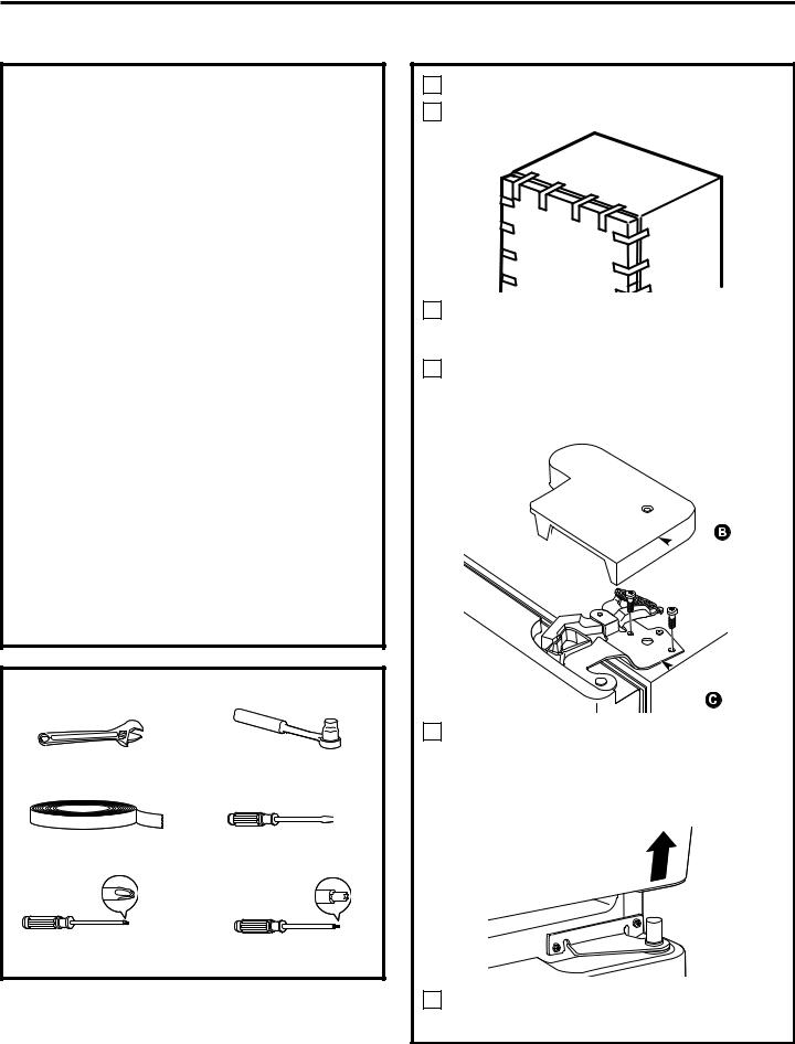
MATERIALS YOU MAY NEED (not included)
Lag Bolts |
Anchor Sleeves |
|
|
Drill Bit Appropriate for Anchors
For Anti-Tip Bracket Mounted on CONCRETEFloors Only
TOOLS YOU MAY NEED |
|
||
Adjustable Wrench |
3/8 |
and 5/16 Socket |
|
|
Ratchet/Driver |
||
|
|
||
1/4″ Outer Diameter |
|
|
|
Compression Nut |
Phillips-Head Screwdriver |
||
and Ferrule (sleeve) (icemaker |
|||
|
|
||
models only) |
|
|
|
3/32″, 1/8″ and 1/4″ Allen |
|||
|
wrenches |
|
|
1/8″ Drill Bit and |
|
Tape measure |
|
Electric or Hand Drill |
|
|
|
Pencil |
1/4″ Nut Driver |
||
Wire Cutters |
|
Level |
|
17

Installation Instructions
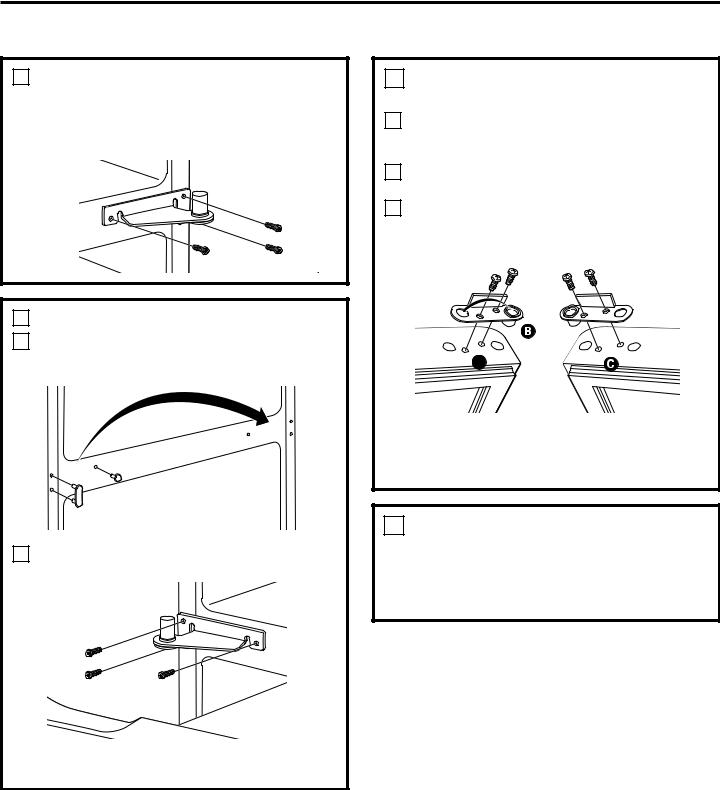
INSTALLINGTHE ANTI-TIPFLOORBRACKET(on 21 ft. models)
 WARNING
Under certain circumstances, this refrigerator can tip forward.
Injury to persons can result.
Install Anti-Tip Bracket packed with this refrigerator.
1MEASURE CABINET OPENING AVAILABLE VS. REFRIGERATOR WIDTH
Measure width of cabinet opening where refrigerator will be placed, W.
Be sure to account for any countertop overhang, baseboard thickness and any clearance desired. Width, W, should not be less than 36 inches. The refrigerator will be placed approximately in the middle of this opening.
|
Baseboard |
|
Rear Wall |
Thickness |
|
or Countertop |
||
|
||
W |
Overhang |
|
(Whichever |
||
|
Is Greater) Plus |
|
|
Any Desired |
|
|
Clearance |
|
REFRIGERATOR |
RH Side |
|
|
||
Front |
|
2LOCATING THE ANTI-TIP FLOOR BRACKET
APlace the anti-tip floor bracket locator template (included inside the anti-tip kit) onto the floor up against the rear wall, within W, and in line with the desired location of the RH side of the refrigerator (see Figure 1).
Figure 1 – Installation Overview
Floor – Concrete |
2 Wall Holes |
|
|
|
|
(2 Holes) |
|
Floor Bracket |
Floor – Wood |
|
to Install |
(2 Holes) |
|
RH Holes |
|
71⁄4″ |
|
|
|
Rear RH Corner |
Base |
|
of Cabinet Wall |
Bracket |
RH Side of |
|
on the |
Locator Template |
|
Refrigerator |
Refrigerator |
Sheet |
BPlace the anti-tip floor bracket onto the locator template with its RH floor holes lined up with
the floor holes indicated″ on the template sheet, approximately 71⁄4 from the edge of the sheet or the RH side of the refrigerator.
CHold down in position and use the anti-tip floor bracket as a template for marking the holes based upon your configuration and type of construction as shown in Step 3. Mark the hole locations with a pencil, nail or awl.
NOTE:
•It is REQUIRED to use at least 2 screws to mount the floor bracket (one on each side of the anti-tip floor bracket). Both must be into either the wall or the floor. Figure 2 indicates all the acceptable mounting configurations for screws. Identify the screw holes on the anti-tip floor bracket for your configuration.
18

Installation Instructions
2LOCATING THE ANTI-TIP FLOOR BRACKET (cont.)
Figure 2 – Acceptable Screw Placement
Locations
Preferred Installation – Wood |
|
Preferred Installation – |
|
|
Concrete |
|
|
|
|
|
|
|
Minimum Acceptable #1 – |
|
|
|
Minimum Acceptable #2 – |
|
|
Wall Plate Stud |
|
|
|
Wood Floor |
|
|
|
|
|
|
|
|
|
|
|
|
|
|
|
Minimum Acceptable #3 –
Concrete Floor
3 ANTI-TIP BRACKET INSTALLATION
AWOOD Wall and Floor Construction:
•Drill the appropriate number of 1/8” pilot holes in the center of each floor bracket hole being used (a nail or awl may be used if a drill is not available) AND remove the locator template from the floor.
•Mount the anti-tip floor bracket by fastening the 2, or preferably 4, #10-16 hex-head screws tightly into place as illustrated in Figure 3.
Figure 3 – |
Attachment to |
|
||
|
Wall and Floor |
|
||
|
2 Screws Must |
Floor |
Wall |
|
Rear RH Corner of |
Bracket |
|
||
Enter Wood or |
|
|||
|
|
|||
the Refrigerator |
|
|
||
Metal Stud |
|
Wall |
||
|
|
|||
|
|
|
|
|
|
|
|
|
Plate |
|
|
|
|
Stud |
|
|
Floor |
|
|
BCONCRETE Wall and Floor Construction:
•Anchors required (not provided): 4 each 1/4” x 1 1/2” lag bolts
4 each 1/2” O.D. sleeve anchors
•Drill the recommended size holes for the anchors into the concrete at the center of the holes marked in Step 2.
•Install the sleeve anchors into the drilled holes. Place the anti-tip floor bracket as indicated in Step 2. Remove the locator template from the floor.
•Install the lag bolts through the anti-tip floor bracket and tighten appropriately.
CWOOD Wall and TILE Floor Construction:
•For this special case, locate the 2 wall holes identified in Fig. 1. Drill an angled 1/8” pilot hole (approx. as shown in Fig. 3) in the center of each hole.
•Mount the anti-tip floor bracket using the Minimum Acceptable Installation #1, as illustrated in Fig. 2.
4POSITIONING THE REFRIGERATOR TO ENGAGE THE ANTI-TIP FLOOR
AND BASE BRACKETS
ABefore pushing the refrigerator into the opening, plug the power cord into the receptacle and connect waterline (if equipped). Check for leaks.
BLocate the refrigerator’s RH side and move back approximately in line with the RH side of the cabinet opening, W. This should position the anti-tip floor bracket to engage the anti-tip base bracket on the refrigerator.
CGently roll the refrigerator back into the cabinet opening until it comes to a complete stop. Check to see if the refrigerator front lines up with the cabinet front face. If not, carefully rock the refrigerator forward and backward until engagement occurs and you notice that the refrigerator is fully pushed up against the rear wall.
DOPTIONAL: Adjust the rear (and front) wheel height settings to fully engage the rear anti-tip brackets, while also aligning the refrigerator front with the cabinet front face.
NOTE:
If you pull the refrigerator out and away from the wall for any reason, make sure the anti-tip floor bracket is engaged when the refrigerator is pushed back against the rear wall.
19

Installation Instructions
INSTALLING THE REFRIGERATOR
REFRIGERATOR LOCATION
•Do not installthe refrigerator where the temperaturewill go below 60°F(16°C) because it will not run often enough to maintain proper temperatures.
•Do not installthe refrigerator where the temperaturewill go above 100°F (37°C)because it willnot performproperly.
•Install it on a floor strong enough to supportit fullyloaded.
CLEARANCES
Allow the followingclearances for ease of installation,proper air circulation and plumbing and electricalconnections.
|
StandardDepth |
Counter Depth |
Sides |
Models |
Models |
1/8″ (3 mm) |
1/8″ (3 mm) |
|
Top |
1″ (25 mm) |
1″ (25 mm) |
Back |
1″ (25 mm) |
1/2″ (13 mm) |
• IMPORTANT NOTE:This refrigerator is 34-1/2″ deep. Doors and passagewaysleadingto″ the installation location must be at least 36 wide in orderto leavethe doors and handles attachedto the refrigeratorwhile transporting it into the installation″ location. If passageways are less than36 , the refrigeratordoors and handles can easily be scratchedand damaged. The top cap and doorscan be removedto allow the
refrigeratorto be safelymovedindoors. StartwithStepA.
• If it is not necessary to remove doors, skipStepA. Leave tape and all packaging on doors until the refrigerator is in the finallocation.
• SKID REMOVAL: Tilt refrigerator to each sideto remove skid.
• NOTE:Use a paddedhand truck to movethis refrigerator.
Placethe refrigerator on the hand truck witha side against the truck. We strongly recommend that TWO PEOPLE move and complete this installation.
ALocate and remove the two Phillips head screwson the top of the refrigerator. Removethe two screws on each side at the rearof the top cap.
Lift off and remove top cap.
BRemove the fresh-fooddoor. Refer to Steps1 through3 of “Reversing the DoorSwing” section.
CRemove the bottomfreezer drawer.Refer to “Removing Freezer Drawer” section.
DMove refrigeratorto the installationlocation.
REMOVE TOP CAP (cont.) (on some models)
REINSTALL DOORS, DRAWERSAND TOPCAP
ECarefullylower the door onto the center hinge. Reinstall top hinge. NOTE: Ensure the door is properlyaligned to the case top to avoid readjustment of the door during top cap reinstallation.
FPlace cap over the top of the refrigerator. Reinstallthe original screws in the top and back of the cap.
GReinstall the bottom freezer drawer. Refer to “Replacing the Freezer Drawer” section.
A
Top Hinge B
1 CONNECTING THE REFRIGERATOR TO THE HOUSE WATER LINE
(icemaker and dispenser models)
A cold water supplyis required for automatic icemaker operation. If there is not a cold water supply, you will need to provide one. See Installing the Water Line section.
NOTES:
•Before making the connectionto the refrigerator,be sure the refrigerator power cord is not plugged into the wall outlet.
•If your refrigerator does not have a water filter, we recommend installing one if your water supply has sand or particles that could clog the screen of the refrigerator’s water valve. Install it in the water line near the refrigerator. If using GESmartConnect™ Refrigerator TubingKit, you will need an additional tube (WX08X10002) to connect the filter.Do not cut plastic tube to install filter.
20
Installation Instructions
1CONNECTINGTHE REFRIGERATOR TO THE HOUSE WATERLINE (cont.)
AIf you are using copper tubing, place a compression nut and ferrule (sleeve) onto the end of the tubing coming from the house cold water supply.
If you are using the GE SmartConnect™ tubing, the nuts are already assembled to the tubing.
BIf you are using copper tubing, insert the end of the tubing into the refrigerator
connection, at the back of the refrigerator, as far as possible. While holding the tubing, tighten the fitting.
If you are using GE SmartConnect™ tubing, insert the molded end of the tubing into the refrigerator connection, at the back of the refrigerator, and tighten the compression nut until it is hand tight. Then tighten one additional turn with a wrench. Overtightening may cause leaks.
CFasten the tubing into the clamp provided to hold it in position. You may need to pry open the clamp.
One of the illustrations below will look like the connection on your refrigerator.
Icemaker-Ready models
1/4″ Copper
Tubing Tubing
Clamp
1/4″ Compression Nut 
Ferrule (sleeve)
Refrigerator |
|
Connection |
SmartConnect™ |
|
Tubing |
Icemaker-Installed Models |
|||
Refrigerator |
Ferrule |
1/4″ |
|
(sleeve) |
Compression |
||
Connection |
|||
|
Nut |
||
|
|
||
SmartConnect™ |
|
|
|
Tubing |
|
|
|
1/4″ Tubing
Tubing Clamp
2 TURN ON THE WATER SUPPLY
(icemaker and dispenser models)
Turn the water on at the shut-off valve (housewater supply) and check for any leaks.
3 PLUG IN THE REFRIGERATOR
On models with an icemaker,before plugging in the refrigerator, make sure the icemaker power switch is set to the O (off) position.
See the grounding information attached to the power cord.
4 PUT THE REFRIGERATOR IN PLACE
Move the refrigerator to its final location. Make sure the back side of the refrigerator engages the anti-tip bracket properly. The anti-tip floor bracket should line up with the cutout in the back bottomof the refrigerator, and fit through the cutout when the refrigerator is pushed into position.(Refer to page 18, Step 2A for more information.)
5 LEVEL THE REFRIGERATOR
Turn the front roller adjusting 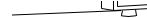 screws clockwise to raise the


 refrigerator, counterclockwise″


to lower it. Use a 3/8 hex wrench with extension, or an
adjustable wrench. Roller adjusting screws
To adjust the rollers on 21‘ CounterDepth models:
These models also have rear adjustable rollers
so you can align the″ refrigerator with your kitchen cabinets. Use a 3/8 hex wrench with extensionto turn the screws for the rear rollers—clockwise to raise the refrigerator, counterclockwise to lower it.
21
Installation Instructions
INSTALLING THE REFRIGERATOR (cont.)
6REMOVE THE FRESH FOOD DOOR HANDLE
(For placement in the installation location or reversal of the handles – on some models)
Stainless steel (on some models):
A REMOVING
THE DOOR HANDLE: |
|
|
Loosen the set |
|
|
screws withthe |
|
|
3/32″ Allenwrench |
|
|
and remove |
Badge |
|
the handle.NOTE: |
||
A |
||
For DoubleDoor |
||
|
||
modelsfollowthe |
|
|
same procedureon |
|
|
the oppositedoor. |
B |
Mounting 
Fasteners
(appearance may vary)
Plastic handle (on some models):
AREMOVING THE DOOR HANDLE:Depress the tab on the underside of the handle and slide the handle up and off of the mounting fasteners.
 REVERSING THE DOOR HANDLE (on some models):
• Remove |
|
the handle |
|
mounting |
B |
fasteners with |
|
a 1/4″ Allen |
|
wrench and |
Badge |
transfer the |
|
handle |
|
mounting |
A |
fasteners to |
|
the rightside. |
|
• Remove the logo |
Mounting |
badge. |
Fasteners |
|
• Remove and
transfer the plug button to
the left side of the fresh fooddoor.NOTE:Use a flat plastic edge to prevent damaging the door.Remove any adhesive on the doorwith a milddetergent.
Remove the paper covering on the adhesivebacking on the logo badge priorto carefully attachingthe badge to the door.
7 REMOVE THE FREEZER DOOR HANDLE
Stainless steel and plastic handles:
ALoosen the set screws″ located″on the underside of the handle with a 1/8 or 3/32 Allen wrench and remove the handle.
NOTE: If the handle mounting fasteners″ needto be tightened or removed,use a 1/4 Allenwrench.
A 
22

Installation Instructions
8ATTACH THE FRESH FOOD DOOR HANDLE
Stainless steel handle:
AAttach the handle to the handle mountingfasteners
and tighten the set″ screws witha 3/32 Allen wrench.
NOTE: For Double Doormodelsfollow the same procedure on the opposite door.
A 
Mounting
Fasteners
(appearance may vary)
Plastic handle:
AAttach the handleto the handle mounting fasteners by aligningthe slotswith the handle mounting fasteners.
 Slide it downuntilit is firmly locked into position.
A
Slots on back of handle
Mounting
Fasteners
A
(appearance may vary)
9 ATTACH THE FREEZER DOOR HANDLE
Stainless steel and plastic handles:
AAttach the handle firmly to the mounting fasteners
and tighten the set″ screws″on the bottomof the handle with a 1/8 or 3/32 Allen wrench.
A
(appearance may vary)
23

Installation Instructions
INSTALLING THE REFRIGERATOR
10 LEVEL THE REFRIGERATOR
The leveling legs have 2 purposes:
1)Leveling legs adjust so the refrigerator is firmly positioned on the floor and does not wobble.
2)Leveling legs serve as a stabilizing brake to hold the refrigerator securely in position during operation and cleaning. The leveling legs also prevent the refrigerator from tipping.
ARemove the grille by removing the two Phillipshead screws.
BTurn the leveling legs clockwise to raise the refrigerator,counterclockwise to lower it.
 CAUTION: To avoid possible personal injury or property damage, the leveling legs must be firmly touching the floor.
CReplace the base grille by inserting the two Phillips-head screws.
(cont.)
11 SET THE CONTROLS
Set the controls to the recommended setting.
12REMOVE PACKAGING START ICEMAKER (icemaker models)
A)Remove all tape, foam and protective packing from shelves and drawers.
B)Remove the tie downs from the freezer baskets.
C)Place half width basket onto drawer slides. See About the freezer section for instructions.
Set the icemaker power switch to the I (on) position. The icemaker will not begin to operate until it reaches its operating temperature of 15°F (–9°C) or below. It will then begin operation automatically. It will take 2–3 days to fill the ice bin.
Power switch
NOTE:
In lower water pressure conditions, the water valve may turn on up to 3 times to deliver enough water to the icemaker.
24

Installation Instructions
REMOVING THE FREEZER DRAWER (on some models)
The freezer drawer can be removed, if needed, to fit through tight areas.
Readthese instructionscompletely and carefully.
1 REMOVE THE BASKET
AOpen the freezer drawer until it stops.
BCut the 2 wire ties off of the basket with wire cutters.
CThe freezer basket rests inside 4 tabs on the freezer slides. Lift the basket up and out of the 4 tabs.
DTilt the front up and lift the entire basket up and out of the drawer.
A
3 REMOVE THE BASE GRILLE
(if needed)
If, after removing the freezer drawer and refrigerator door, the refrigerator will still not fit through a doorway, the base grille can be removed.
ARemove the base grille by removing the 2 Phillips-head screws.
2REMOVE THE DRAWER FRONT FROM THE SLIDES
ARemove the 10 hex-head screws from the door and remove the door.
DO NOT remove the torx screws from the rail assemblies.
DO NOT remove torx screws
Rail Assembly
BSet the drawer front on a non-scratching surface.
CPush the rail assemblies back into the cabinet.
25

Installation Instructions
REPLACING THE FREEZER DRAWER (on some models)
Two people may be required to complete this procedure.
1ATTACH AND SECURE THE DRAWER FRONT TO THE SLIDES
APull out the rail assemblies to the full length on each side of the cabinet.
BDrive the top screw into the door on each side until it is 1/2 way in.
Screw
CHang the drawer front onto open slots on the slides.
Slot
1ATTACH AND SECURE THE DRAWER FRONT TO THE SLIDES (CONT.)
D Drive screws fully. (There are 10 screws.)
Screw
Step D2:
Drive fully.
Step D3: |
|
|
Drive |
|
|
screws in |
Step D1: |
|
these |
||
Line up |
||
holes. |
||
screw hole |
||
|
||
|
in freezer |
|
|
drawer and |
|
|
drive fully. |
2 REPLACE THE FREEZER BASKET
Replace the lower freezer basket by lowering it into the frame.
26
Installation Instructions
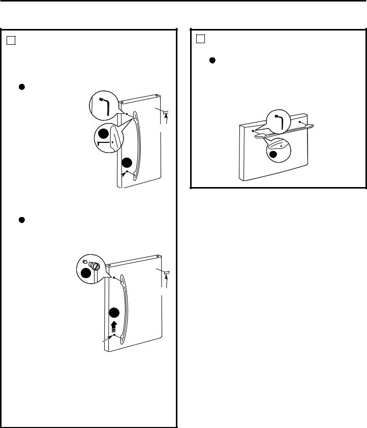
REVERSINGTHE DOOR SWING (Single Door Refrigerator Models only)
IMPORTANT NOTES
Whenreversingthe doorswing:
NOTE: Door swing is not reversibleon stainlesssteel models.
•Readthe instructionsall the way throughbefore starting.
•Parts are includedin the door hingekit.
•Handle parts carefullyto avoidscratchingpaint.
•Set screws down by theirrelatedpartsto avoid using them in the wrongplaces.
•Provide a non-scratchingworksurfacefor the doors.
IMPORTANT: Onceyou begin,do not move the cabinet untildoor-swing reversalis completed.
These instructionsare for changingthe hinges from the right side to the left side—ifyou everwant to change the hinges back to the rightside, follow these same instructionsand reverseall referencesto leftand right.
•Oncedoorswingis finalized, ensurethe logobadge is properly aligned and permanentlysecured to the door by removingthe adhesive cover on the back side.
NOTE: A replacement logobadgeis includedin the hinge kit.
Unplug the refrigerator from its electricaloutlet.
Empty all door shelves,including the dairy compartment.
TOOLS YOU WILL NEED
Adjustable Wrench 5/16″ Socket Ratchet/Driver
Masking Tape |
Thin-blade Screwdriver |
|
|
|
|
|
|
|
|
|
|
|
|
|
Phillips Screwdriver |
Torx T-20 Driver |
1 REMOVE THE REFRIGERATOR DOOR
A Tape the door shut with masking tape.
BRemove the hinge cover on top of the refrigerator door by removing the Phillips-head screws and pulling it up.
CUsing a 5/16″ socket ratchet/driver,remove the bolts securing the top hinge to the cabinet. Then lift the hinge straight up to free the hinge pin from the socket in the top of the door.
 Hinge Cover
 Top Hinge
DRemove the tape and tilt the door away from the cabinet. Lift the door off the center hinge pin. Ensure that the plastic hinge pin thimble remains on the hinge pin or inside door hinge pin hole located in the bottom of the door.
ESet the door on a non-scratching surface with the inside up.
27
Installation Instructions
REVERSING THE DOORSWING(cont.)
2 REMOVE CENTER HINGE
Using a 5/16″ socket ratchet/driver, remove the bolts securing the center hinge to the cabinet. Set the hinge and bolts aside.
3 INSTALLCENTERHINGE
ATransfer the plug button and screw hole cover in the hinge holes on the left side to the right side.
BInstall the center hinge from the kit on the left side.
4TRANSFER REFRIGERATOR DOOR STOP
ARemove the door stop on right side of the bottom of the refrigerator door by removing the two screws.
BMove the plastic hinge hole thimble to the opposite hole.
CInstall the door stop on the left side, making sure to line up the screw holes in the door stop with the holes in the bottom of the door.
A
Bottom of |
|
Bottom of |
Refrigerator Door |
|
Refrigerator Door |
(Right Side) |
|
(Left Side) |
|
|
|
5TRANSFER REFRIGERATOR DOOR HANDLE TO RIGHT
Refer to Remove the Fresh Food Door Handle and Attach the Fresh Food Door Handle sections for instructions.
NOTE: A new hinge will be requiredfor the leftside (supplied in the door hingekit).
28

Installation Instructions
6
A
B
C
REHANG REFRIGERATORDOOR
Lower the refrigerator door onto the center hinge pin. Ensure that the plastic hinge pin thimble is on the center hinge pin or inside door hinge pin hole located in the bottom of the door.
Insert the top hinge pin into the hinge hole on top of the refrigerator door. Make sure the door is aligned with the cabinet. Attach the hinge to the top of the cabinet loosely with the bolts.
Make sure the gasket on the door is flush against the cabinet and is not folded. Support the door on the handle side and make sure the door is straight and the gap between the doors is even across the front. While holding the door in place, tighten the top hinge bolts. Replace the hinge cover.
7 INSTALL THE LOGO BADGE
Remove the adhesive backing paper
and align the pins on the back of the badge with the holes in the door. Apply pressure to the badge to ensure it sticks to the door.
29
Installation Instructions
REMOVING THE DOORS(Double Door Refrigerator Models only)
IMPORTANT NOTES
NOTE: Door swing is not reversible.
•Read the instructions all the way through before starting.
•Handle parts carefully to avoid scratching paint.
•Set screws down by their related parts to avoid using them in the wrong places.
•Provide a non-scratching work surface for the doors.
IMPORTANT: Once you begin, do not move the cabinet.
These instructions are for removing the doors.
Unplug the refrigerator from its electrical outlet.
Empty all door shelves, including the dairy compartment.
TOOLS YOU WILL NEED
|
3/8″ and 10 mm Socket |
|
|
Adjustable Wrench |
|
|
Ratchet/Driver |
Masking Tape |
Thin-blade Screwdriver |
|
|
Phillips Screwdriver
1 REMOVE THE REFRIGERATOR DOORS
A Tape the doors shut with masking tape.
(for water dispenser models)
BStart with right-hand door first: Remove the screw securing the center hinge cover, lift the hinge cover and place to the side on top of the refrigerator.
Remove hinge cover (1 Phillips screw)
(for water dispenser models)
C Remove water coupling and power coupling.
C1
Water Coupling
Remove the metal spring clip. Use a screwdriver to  push the red plastic locking clip down and off.
C2 |
|
Water Coupling |
|
Push red collar |
|
and hold. |
Pull tube. |
C3
Power Coupling
Black mark flush with collar assembly
Pull apart power coupling to disconnect
30
 Loading...