

Page 1
SETUP & OPERATION MANUAL
FEATURES
Simple design for easy set-up and maintenance.
High static pressure output for quiet and effective dust collection.
12 ¾” Precision spin-balanced aluminum impeller for smooth operation, minimal noise, and
reduced risk of sparking.
Non-sparking housing with easy-to-clean collection drawers inside the cabinet.
Top-mounted full-width handle and four swivel
casters (2 locking) on the base for complete
mobility and stability.
Large paddle-style stop switch with safety lockout pin to prevent unauthorized use.
Superior 3-stage 5/1 micron filtration system
includes; pleated, carbon, and stainless steel
filters.
Tool-free filter changes.
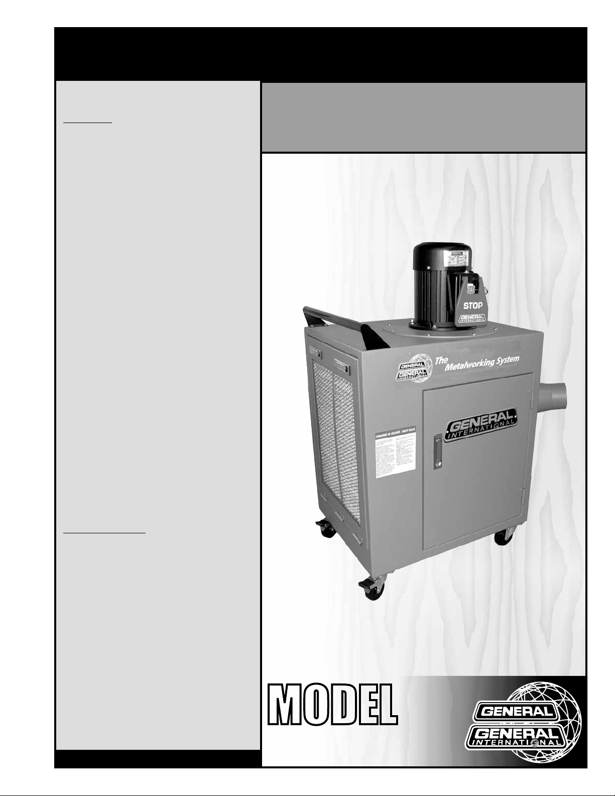
METAL DUST COLLECTOR - 1 ½ HP
SPECIFICATIONS
• Inlet diameter
(1) 6” (152 mm) (or 2) 4” (102 mm)
• Airflow capacity
755 cfm
• Blower wheel diameter
12 ¾”
• Sound rating
85 dB
• Collection drawer dimensions (2)
17 ¾” x 13 ½” x 7 7⁄8” (450 x 345 x 200 mm)
4 ½” x 18 ½” x 3” (115 x 465 x 75 mm)
• Static pressure
8 5⁄8” of water
• Overall dimensions
19 5⁄8” x 38 ¼” x 43 5⁄8” (500 x 970 x 1110 mm)
• Motor M1
1 ½ HP, 220 V, 6.5 A, 3450 rpm
• Weight
183 lbs (83 kg)
Version #2_Revision#2 - April, 2016
© Copyright General International
MODEL
#
10-950
Page 2

GENERAL® INTERNATIONAL
8360 Champ-d’Eau, Montreal (Quebec) Canada H1P 1Y3
Telephone (514) 326-1161 • Fax (514) 326-5555 • www.general.ca
THANK YOU
for choosing this General® International model 10-950 Metal
dust collector. This dust collector has been carefully tested and inspected before shipment
and if properly used and maintained, will provide you with years of reliable service. For your
safety, as well as to ensure optimum performance and trouble-free operation, and to get
the most from your investment, please take the time to read this manual before assembling,
installing and operating the unit.
The manual’s purpose is to familiarize you with the safe operation, basic function, and features
of this dust collector as well as the set-up, maintenance and identification of its parts and
components. This manual is not intended as a substitute for formal metalworking instruction,
nor to offer the user instruction in the craft of metalworking. If you are not sure about the safety
of performing a certain operation or procedure, do not proceed until you can confirm, from
knowledgeable and qualified sources, that it is safe to do so.
Once you’ve read through these instructions, keep this manual handy for future reference.
DISCLAIMER: The information and specifications
in this manual pertain to the unit as it was supplied
from the factory at the time of printing. Because we
are committed to making constant improvements,
General® International reserves the right to make
changes to components, parts or features of this
unit as deemed necessary, without prior notice and
without obligation to install any such changes on
previously delivered units. Reasonable care is taken
at the factory to ensure that the specifications and
information in this manual corresponds with that of the
unit with which it was supplied. However, special orders
and “after factory” modifications may render some
or all information in this manual inapplicable to your
machine. Further, as several generations of this model
dust collector and several versions of this manual may
be in circulation, if you own an earlier or later version of
this unit, this manual may not depict your unit exactly. If
you have any doubts or questions contact your retailer
or our support line with the model and serial number of
your unit for clarification.
Page 3

GENERAL® INTERNATIONAL WARRANTY
All component parts of General® International and Excalibur by General International® products
are carefully inspected during all stages of production and each unit is thoroughly inspected upon
completion of assembly.
Limited Lifetime Warranty
Because of our commitment to quality and customer satisfaction, General® International agrees to
repair or replace any part or component which upon examination, proves to be defective in either
workmanship or material to the original purchaser for the life of the tool. However, the Limited Lifetime
Warranty does not cover any product used for professional or commercial production purposes nor
for industrial or educational applications. Such cases are covered by our Standard 2-year Limited
Warranty only. The Limited Lifetime Warranty is also subject to the “Conditions and Exceptions” as listed
below.
Standard 2-Year Limited Warranty
All products not covered by our lifetime warranty including products used in commercial, industrial and
educational applications are warranted for a period of 2 years (24 months) from the date of purchase.
General® International agree to repair or replace any part or component which upon examination,
proves to be defective in either workmanship or material to the original purchaser during this 2-year
warranty period, subject to the “conditions and exceptions” as listed below.
To file a Claim
To file a claim under our Standard 2-year Limited Warranty or under our Limited Lifetime Warranty,
all defective parts, components or machinery must be returned freight or postage prepaid to
General® International, or to a nearby distributor, repair center or other location designated by
General® International. For further details call our service department at 1-888-949-1161 or your local
distributor for assistance when filing your claim.
Along with the return of the product being claimed for warranty, a copy of the original proof of purchase
and a “letter of claim” must be included (a warranty claim form can also be used and can be obtained,
upon request, from General® International or an authorized distributor) clearly stating the model and
serial number of the unit (if applicable) and including an explanation of the complaint or presumed
defect in material or workmanship.
CONDITIONS AND EXCEPTIONS:
This coverage is extended to the original purchaser only. Prior warranty registration is not required but
documented proof of purchase i.e. a copy of original sales invoice or receipt showing the date and
location of the purchase as well as the purchase price paid, must be provided at the time of claim.
Warranty does not include failures, breakage or defects deemed after inspection by General®
International to have been directly or indirectly caused by or resulting from; improper use, or lack of or
improper maintenance, misuse or abuse, negligence, accidents, damage in handling or transport, or
normal wear and tear of any generally considered consumable parts or components.
Repairs made without the written consent of General® International will void all warranty.
Page 4

TABLE OF CONTENTS
Rules for safe operation ..................................................................................................... 5
Electrical requirements ...................................................................................................... 6
Identification of main parts and components .................................................................. 7
Unpacking .......................................................................................................................... 8
Basic functions ................................................................................................................... 8
Placement within the shop ................................................................................................ 9
Placement within the shop ................................................................................................................................ 9
Connection of the machine .............................................................................................................................. 9
Assembly instructions ................................................................................................... 9-10
Installing swivel casters ...................................................................................................................................... 9
Installing the inlet mount & hose inlet ............................................................................................................ 10
Basic adjustments and controls ................................................................................. 10-11
Connecting to a power source .......................................................................................................................10
ON/OFF power switch ....................................................................................................................................... 10
Using the power switch ..................................................................................................................................... 11
Overload protection/Circuit-breaker ............................................................................................................. 11
Checklist before and after starting ................................................................................................................. 12
Maintenance .................................................................................................................... 12
Cleaning/Replacing filters .............................................................................................................................. 12
Cleaning the dust drawers .............................................................................................................................. 13
Other routine checks ........................................................................................................................................ 13
Recommended optionnal accessories ........................................................................... 14
Parts list & diagram .................................................................................................... 15-16
Contact information ........................................................................................................ 18
Page 5

RULES FOR SAFE OPERATION
To help ensure safe operation, please take a moment to learn the machine’s applications and limitations,
as well as potential hazards. General
harmless for any injury that may result from the improper use of it’s equipment.
1. Do not operate the dust collector when tired, dis-
tracted, or under the effects of drugs, alcohol or
any medication that impairs reflexes or alertness.
2. The working area should be well lit, clean and free
of debris.
3. Keep children and visitors at a safe distance when
the dust collector is in operation; do not permit
them to operate the dust collector.
4. Childproof and tamper proof your shop and all
machinery with locks, master electrical switches
and switch keys, to prevent unauthorized or unsu
perviseduse.
5. Stay alert! Give your work your undivided attention.
Even a momentary distraction can lead to serious
injury.
6. Fine particulate dust is a carcinogen that can be
hazardous to health. Work in a well-ventilated area
and wear face, eye, ear, respiratory and body pro
tection devices.
7. Do not wear loose clothing, gloves, bracelets, neck
laces or other jewelry while the dust collector is in
operation. Wear protective hair covering to contain
long hair and wear non-slip footwear.
8. Do not insert hands, fingers or any foreign objects
into ventilation inlet and outlet openings. Do not cut
or break the intake screen in the inlet.
9. Do not operate this machine without all filters prop
erly installed on the unit.
10. Clean filters on a regular basis and replace as
needed.
11. Do not handle the electrical plug with wet hands.
12. Do not use this unit outdoors, on or near wet sur
faces.
13. Always turn on the dust collector before starting the
dust producing machine. Always turn off the dust
producing machine before turning off the dust col
lector.
®
International disclaims any real or implied warranty and holds itself
14. Do not vacuum glass, water or anything that is
burning, smoking or smoldering such as cigarettes,
matches or hot ashes.
15. Do not vacuum or use this dust collector near flam
mable or combustible liquids, gases, gasoline
or other fuels, lighter fluid, cleaners, oil or solvent
based paints, natural gas, hydrogen or explosive
dusts like coal dust, magnesium dust, grain dust or
gun powder.
16. Do not operate the unit until a dust hose is installed
-
-
-
-
-
-
onto the hose inlet and make sure all the joints and
connectors are properly installed.
17. Never leave the machine unattended while it is run
ning or with the power on.
18. To avoid health hazards from vapors or dusts, do
not vacuum toxic material.
19. Use only recommended accessories. Use of acces
sories NOT recommended by GENERAL® INTERNATIONAL may result in a risk of injury or damage to
the machine.
20. Always disconnect the unit from the power source
before servicing, performing any maintenance or
repairs and when changing bags or hoses, or if the
machine will be left unattended.
21. Make sure that the switch is in the“OFF”position be
fore plugging in the power cord.
22. Make sure the tool is properly grounded. If equipped
with a 3-prong plug, it should be used with a three
pole receptacle. Never remove the third prong.
23. Never stand or lean on machinery. Serious injury
could result if the tool is tipped over.
24. Do not use this dust collector for any purpose other
than its intended use. If used for other purposes,
GENERAL® INTERNATIONAL
plied warranty and holds itself harmless for any injury, which may result from that use.
disclaims any real or im-
-
-
-
-
-
IMPORTANT NOTICE
The sound level of this machine is rated at approximately 85 dB during operation. Make sure that adequate hearing protection is used and that the overall sound level within the working environment is taken into consideration.
5
Page 6
ELECTRICAL REQUIREMENTS
BEFORE CONNECTING THE MACHINE TO THE POWER SOURCE, VERIFY THAT THE VOLTAGE OF YOUR POWER SUPPLY CORRESPONDS WITH THE VOLTAGE SPECIFIED ON THE MOTOR I.D. NAMEPLATE. A POWER SOURCE WITH
GREATER VOLTAGE THAN NEEDED CAN RESULT IN SERIOUS INJURY TO THE USER AS WELL AS DAMAGE TO THE
MACHINE. IF IN DOUBT, CONTACT A QUALIFIED ELECTRICIAN BEFORE CONNECTING TO THE POWER SOURCE.
THIS TOOL IS FOR INDOOR USE ONLY. DO NOT EXPOSE TO RAIN OR USE IN WET OR DAMP LOCATIONS.
A
C
B
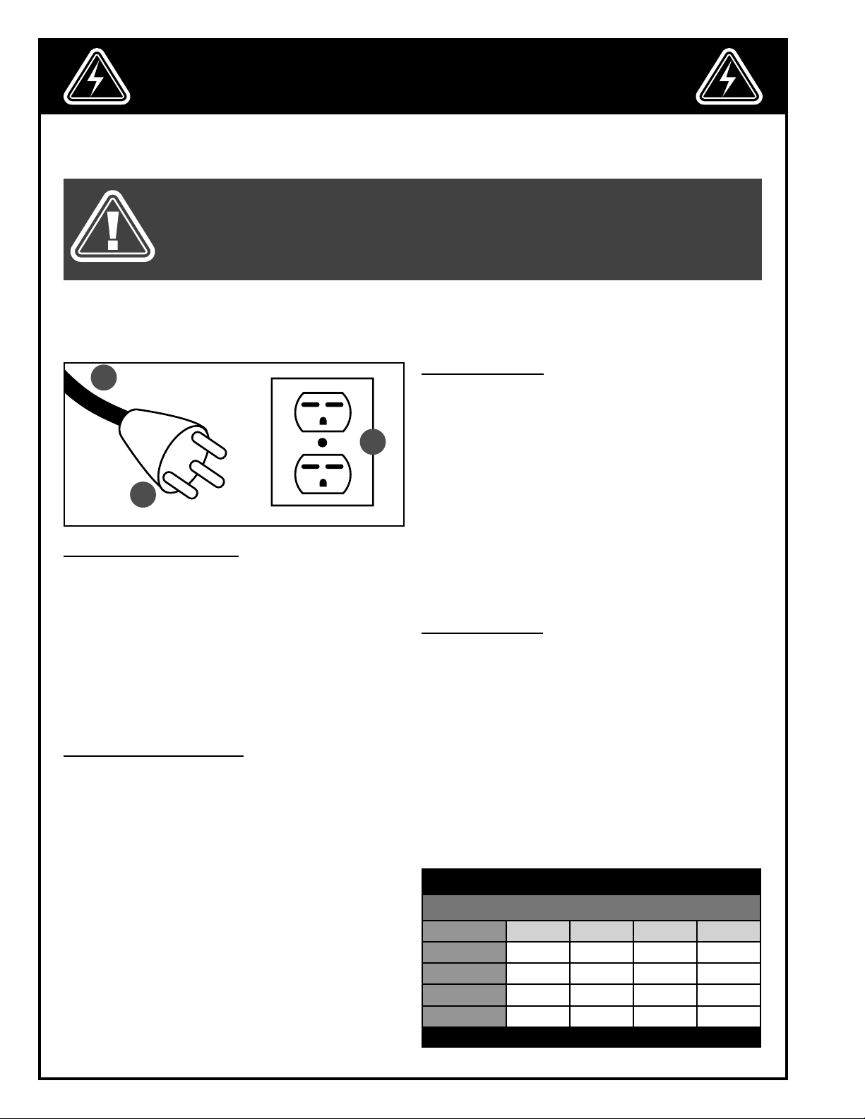
ELECTRICAL CONNECTIONS
Both a manual circuit breaker (or similar device) as
well as an electrical plug (similar to the one shown) are
recommended and should be installed by a qualified
electrician.
Use locally approved wire A that includes a separate
grounding wire and a 3-prong grounding type plug B
with a matching receptacle C.
GROUNDING INSTRUCTIONS
In the event of an electrical malfunction or short circuit, grounding reduces the risk of electric shock to the
operator.
The motor of the “M1” model of this machine is wired
for 220 V single phase operation. As with many stationary industrial type machines, because each installation situation is unique, this planer is supplied without
a plug. The installation of an appropriate plug must be
performed by a qualified electrician.
The machine must be connected to an electrical
source using a power cord that has a grounding wire,
which must also be properly connected to the grounding prong on the plug. The outlet must be properly installed and grounded and all electrical connections
must be made in accordance with all local codes and
regulation.
CIRCUIT CAPACITY
Make sure that the wires in your circuit are capable of
handling the amperage draw from your machine, as
well as any other machines that could be operating on
the same circuit. If you are unsure, consult a qualified
electrician.
If the circuit breaker trips or the fuse blows regularly,
your machine may be operating on a circuit that is
close to its amperage draw capacity. However, if an
unusual amperage draw does not exist and a power
failure still occurs, contact a qualified technician or our
service department.
EXTENSION CORDS
If you find it necessary to use an extension cord with
your machine, use only 3-wire extension cords that have
3-prong grounding plug and a matching 3-pole receptacle that accepts the tool’s plug. Repair or replace a
damaged extension cord or plug immediately.
Make sure the cord rating is suitable for the amperage
listed on the motor I.D. plate. An undersized cord will
cause a drop in line voltage resulting in loss of power
and overheating.
The accompanying chart shows the correct size extension cord to be used based on cord length and motor
I.D. plate amp rating. If in doubt, use the next heavier
gauge. The smaller the number, the heavier the gauge.
TABLE - MINIMUM GAUGE FOR CORD
EXTENSION CORD LENGTH
AMPERES 50 feet 100 feet 200 feet 300 feet
< 5
6 to 10
10 to 12
12 to 16
*NR = Not Recommended
18 16 16 14
18 16 14 12
16 16 14 12
14 12 *NR *NR
6
Page 7

IDENTIFICATION OF MAIN PARTS AND COMPONENTS
D
E
F
C
G
H
B
A
A. LOCKABLE SWIVEL CASTERS (2)
B. ACCESS DOOR FILTER/TRAY
C. HANDLE
D. MOTOR
E. OVERLOAD PROTECTION/CIRCUIT-BREAKER
I
J
F. SAFETY LOCK-OUT PIN
G. PADDLE-STYLE STOP SWICH
H. HOSE INLET
I. ACCESS DOOR DUST DRAWER
J. SWIVEL CASTERS (2)
7
Page 8

UNPACKING
Carefully unpack and remove the unit and its components from its shipping container and check for missing or
damaged items as per the list of contents below.
NOTE: PLEASE REPORT ANY DAMAGED OR MISSING ITEMS TO YOUR GENERAL® INTERNATIONAL DISTRIBUTOR IMMEDIATELY.
LIST OF CONTENTS QTY
A. DUST COLLECTOR .................................................................... 1
B. HEX. FLANGE BOLT ................................................................. 16
C. 5 MM ALLEN KEY ..................................................................... 1
D. 12 & 10 MM COMBINATION WRENCH ................................... 1
E. HEX. BUTTON SOCKET CAP SCREW ......................................... 4
F. LOCKABLE SWIVEL CASTER ..................................................... 2
G. SWIVEL CASTER ........................................................................ 2
H. PHILLIPS HEAD SCREW ............................................................. 1
I. 6” TO 2 X 4” Y-INLET ................................................................. 1
J. INLET MOUNT ........................................................................... 1
ADDITIONAL REQUIREMENTS FOR SET UP
A. EXTRA PERSON FOR HELP WITH LIFTING
B. PHILLIPS SCREWDRIVER
A
B
A
C
B
F
I
D
E
G
J
H
BASIC FUNCTIONS
This model 10-950 1 1/2 HP Metal Dust collector is designed to efficiently collect and filter metallic dust for metalworking shop activities such as grinding, sanding and polishing.
The 3-stage filtration system includes a stainless steel inner filter that can capture larger debris and metal dust, an
intermediate active charcoal filter to capture finer particles as small as 5 microns, and a pleated outer filter de
signed to capture particles as small as 1 micron.
NOTE: THIS UNIT IS NOT DESIGNED TO REPLACE PERSONAL BREATHING PROTECTION DEVICES SUCH AS RESPI
RATORS OR DUST MASKS. TO ENSURE YOUR PERSONAL PROTECTION YOU MUST CONTINUE TO USE PERSONAL
BREATHING PROTECTION DEVICES WHENEVER RECOMMENDED FOR THE OPERATION OR WORK BEING PER
FORMED.
To ensure efficiency and maximize service life, make sure to check and clean the filters regularly and replace
them as needed. To avoid potentially costly down time, consider keeping a spare set of replacement filters on
hand and nearby for use when needed.
Order spare replacement filters as soon as you take your spare “back-up” filter out of storage and put it into use.
Replacement filters can be ordered through your local General International dealer/distributor. For a complete list
of distributors consult the listing on the General International website at: www.general.ca
8
-
-
-
Page 9

PLACEMENT WITHIN THE SHOP / SAFETY ZONE
THIS DUST COLLECTOR MODEL 10-950 IS HEAVY. DO NOT OVER-EXERT. A HOIST OR FORKLIFT WITH STRAPS SHOULD BE USED
TO LIFT THIS MACHINE. TO LIMIT THE RISK OF SERIOUS INJURY OR DAMAGE TO THE MACHINE, ANY EQUIPMENT USED TO LIFT
THIS MACHINE SHOULD HAVE A RATED CAPACITY IN EXCESS OF 183 LBS (83 KG).
PLACEMENT WITHIN THE SHOP
The unit should be installed as close to the dust source(s) as possible. The base of the unit is mounted on casters and
as such the dust collector can be moved from one location to another within the shop if a permanent installation
location is not practical or desired. In all cases the unit should be installed on a flat, sturdy and stable surface that
is able to support the weight of the unit and its contents, as well as the weight of the operator. The casters should be
blocked to prevent the unit from moving when it is in use.
CONNECTION OF THE MACHINE
THE 10-950 METAL DUST COLLECTOR CANNOT BE CONNECTED TO A MACHINE EQUIPPED WITH A COOLANT RESERVOIR. ALSO, THE 10-950 MODEL IS NOT DESIGNED TO REMOVE WOOD DUST OR WET DUST. DUE TO THE POTENTIALLY
HIGH TEMPERATURE CHIPS, PLEASE USE ONLY HOSE AN ALUMINUM HOSE. FAILURE TO FOLLOW THESE SAFETY RULES
CAN RESULT IN SERIOUS INJURY TO THE USER AS WELL AS DAMAGE TO THE MACHINE.
To avoid accidents as well as damage to ducting or hoses, plan your installation with hoses and ducting running
along walls or mounted from above wherever possible.
Wherever possible avoid running hoses and
ducting along the floor.
Keep hoses and ducting safely mounted along
the walls.
ASSEMBLY INSTRUCTIONS
BEFORE STARTING THE ASSEMBLY, MAKE SURE THAT THE SWITCH IS IN THE “OFF” POSITION AND THAT THE POWER
CORD IS UNPLUGGED. DO NOT PLUG IN OR TURN ON THE DUST COLLECTOR UNTIL YOU HAVE COMPLETED THE
ASSEMBLY AND INSTALLATION STEPS DESCRIBED IN THIS SECTION OF THE MANUAL.
TIP: TO INSTALL THE SWIVEL CASTERS, LAY THE MACHINE ON ITS SIDE. TO PREVENT SCRATCHES OR DAMAGE ON THE COLLECTOR,
FIRST PLACE A PIECE OF CARDBOARD ON THE GROUND UNDER THE MACHINE.
INSTALL THE SWIVEL CASTERS
Note: The two lockable swivel casters B must be
installed on the handle side as shown. Attach the 4
wheels to the machine using the hex. head bolts A and
the supplied 12 mm combination wrench.
A
B
9
Page 10

INSTALL THE INLET MOUNT AND THE HOSE INLET
A
1. Align the holes located on the right side of the ma-
chine with the holes of the inlet mount as shown.
Note: The hole A should be on top.
A
2. Attach the inlet mount using the cap screws A and
the supplied Allen key as shown.
A
B
A
3. Slide the hose inlet onto the inlet mount and align
the holes A.
4. Attach the hose inlet using the screw A as shown.
Note: For maximum efficiency, a supplied cover
should be installed on any unused hose inlet
openings, B
BASIC ADJUSTMENTS & CONTROLS
TO REDUCE THE RISK OF SHOCK OR FIRE DO NOT OPERATE THE UNIT WITH A DAMAGED POWER CORD OR PLUG. REPLACE
DAMAGED CORD OR PLUG IMMEDIATELY. TO AVOID UNEXPECTED OR UNINTENTIONAL START-UP, MAKE SURE THAT THE POWER
SWITCH IS IN THE OFF POSITION BEFORE CONNECTING TO A POWER SOURCE.
CONNECTING TO A POWER SOURCE
Once the assembly steps have been completed, plug the power cord into an appropriate outlet. Refer back to the
section entitled “Electrical Requirements” and make sure all requirements and grounding instructions are followed.
When operations have been completed unplug the planer from the power source.
ON/OFF POWER SWITCH
This dust collector is equipped with a safety switch. It includes a GREEN “START” button A, an extra-large easy
access RED stop panel B, and a lock-out pin C to pre
vent unwanted or unintentional start-up and unauthorized use of the machine.
-
A
C
B
10
Page 11

USING THE POWER SWITCH
TO PREVENT ANY USE OF THE MACHINE BY AN UNAUTHORIZED PERSON, IT IS RECOMMENDED TO REPLACE THE LOCK
PIN AND UNPLUG THE COLLECTOR FROM THE POWER SOURCE WHEN THE MACHINE IS NOT USED.
To start the machine: Lift the red stop panel C, remove
the pin A as shown and then push on the green start
button B.
To stop the machine: Press on the red “STOP” panel C.
The machine can be restarted by pushing on the green
button B.
To lock the machine: Lift the red “STOP” panel C and
insert the key A in the hole located behind the green
button B.
OVERLOAD PROTECTION/CIRCUIT BREAKER
The switch on this machine is equipped with an overload protection feature.
To prevent an electrical overload from damaging the
motor, in the event of a spike in line voltage or amperage draw, the internal overload protector will automatically be tripped, thereby cutting off power to the motor.
To restart the machine, first press the reset overload button A located on the top of the switch box and push on
the green button .
A
C
B
A
CHECKLIST BEFORE AND AFTER STARTING
VERIFY ALL CHECK POINTS BEFORE STARTING. FAILURE TO COMPLY CAN RESULT IN SERIOUS INJURIES.
• Make sure you and any assistants are wearing safe and appropriate workshop attire.
• To reduce the risk of damage to the machine, as well as a potential for personal injury, after initial set-up as well
as before each use, make sure that everything is securely installed and that all fasteners and moving parts on
this machine are locked in place before starting the machine.
• Make sure the inlet mount is properly intalled, and check the inlet hose is properly connected to the dust collec
tor and to the machine producing the dust.
• Make sure to have on safety glasses as well as hearing & respiratory protection at all times when using the
machine.
-
11
Page 12

MAINTENANCE
MAKE SURE THE MACHINE HAS BEEN TURNED OFF AND UNPLUGGED FROM THE POWER SOURCE BEFORE PERFORMING ANY MAINTENANCE.
All accessories mentioned in this section are available from your General International distributor or our Parts Department - contact information can be found on the last page of this manual.
NOTE: ALL BEARINGS ARE SEALED AND PERMANENTLY LUBRICATED. NO FURTHER LUBRICATION IS NEEDED.
CLEANING/REPLACING FILTERS
TIP: FINE PARTICLE DUST IN THE FILTER CAN BE HAZARDOUS TO YOUR HEALTH. IT IS RECOMMENDED TO WEAR RESPIRATORY
PROTECTION AND GLOVES BEFORE HANDLING AND CLEANING THE FILTERS.
A
C
A
B
1. To open the access door C pull the two levers A and
turn clockwise as shown B.
3. Remove and inspect the three filters, and clean or
replace as follow:
Stainless steel filter A: Unless damaged (by holes, cuts,
or a broken frame) this filter should not require replacing. A simple cleaning can be done with water or compressed air every 10-15 hours of operation, or any time
you notice a drop in the overall airflow of the unit.
Active carbon filter B: Place the filter in a clean dry
location to air dry and then use a soft bristle brush to
gently remove any larger visible dust particles. Do this
every 25-30 hours of operation or any time you notice
a drop in the overall airflow of the unit. Replace the filter
after 300 hours of operation or when cleaning the filter
no longer improves overall airflow of the unit, as this is a
sign that the filter is permanently clogged.
1 micron filter C: Use low pressure air (blower or vacuum) or a soft bristle brush to gently clean the filter every
35-40 hours of operation, or any time you notice a drop
in the overall airflow of the unit. Replace the filter after
300 hours of operation or when cleaning the filter no longer improves overall airflow, as this is a sign that the filter is
permanently clogged.
4. Re-install the filters in the order shown when finished the cleaning. Note: Consider the arrow E located on one
side of the filter before re-installing it.
5. Fold the two tabs holding filters D and close the access door filters.
2. Lift the two tabs A to release the filters.
C
B
A
TIP: TO AVOID POTENTIALLY COSTLY DOWNTIME, CONSIDER HAVING A SPARE SET OF REPLACEMENT FILTERS ON
HAND AND READY FOR USE WHEN NEEDED.
D
E
NOTE: FILTER CLEANING AND REPLACEMENT INFORMATION IS SUPPLIED AS A GENERAL GUIDELINE ONLINE ONLY. YOUR RESULTS MAY VARY BASED ON THE FREQUENCY AND INTENSITY OF USE, AND DEPENDING ON THE VOLUME AND TYPE OF DUST
BEING COLLECTED.
12
Page 13

CLEANING THE DUST TRAYS
TIP: RESIDUE IN THE DRAWERS MAY BE HAZARDOUS TO HEALTH. IT IS RECOMMENDED TO WEAR GLOVES AND RESPIRATORY
PROTECTION BEFORE HANDLING AND CLEANING THE DUST DRAWERS OF YOUR MACHINE.
A
C
B
1. To open the access door C pull the two levers A and
turn it clockwise as shown B.
A B
2. To empty the dust tray remove it as shown. Make
sure to re-install it before closing the door.
3. To open the front access door pull up the lever A,
and turn it clockwise as shown, B.
OTHER ROUTINE CHECKS
• Periodically inspect all hardware, fittings and fasteners that may have loosened due to vibration - retighten as
needed.
• To minimize airborne dust particles periodically inspect all dust collection fittings. Retighten as needed.
• Periodically inspect inside of all pipes, fittings, hoses, blast gates, and connectors for accumulated dust build-
up or other obstructions, and clean as needed. Vacuum or manually remove debris as needed.
• Do not operate with a damaged filters - replace a damaged filter immediately.
• Periodically inspect the power cord and plug for damage. If necessary replace the power cord and plug at
the first signs of visible damage.
• Use only recommended parts and accessories. The use of parts or accessories NOT recommended by
GENERAL® INTERNATIONAL may result in a risk of injury or damage to the machine.
4. To empty the dust tray remove it as shown. Make
sure to re-install it before closing the door.
13
Page 14

RECOMMENDED OPTIONAL ACCESSORIES
We offer a large variety of products to increase convenience, productivity, accuracy and safety when using your
machine. Here’s a small sampling of optional accessories available from your local General® International dealer. For more information about our products, please visit our website at www.general.ca
Item #10-089
4” HOSE CLAMP
Item #10-951
STAINLESS FILTER
Designed to filter
larger debris and
metal dust (30
microns). Cleans
with water or
compressed air.
Dimensions: 19
3/8” x 15 3/8” x
1/8” (492 x 391 x 3
mm).
Item #10-952
ACTIVE CARBON FILTER
Filters finer particles down to 5
microns. Dimen
sions: 19 3/8” x
15 3/8” x 7/8”
(492 x 391 x 22
mm).
-
Item #10-955
4” FLEXIBLE/EXPANDABLE ALUMINIUM HOSE
For metallic dust. Minimum/Maximum length:
33”/98”.
Item #10-953
1 MICRON
PLEATED OUTER
MICRO-FILTER
Easy to install,
and cleans with
diffused air or soft
bristle brush. Di
mensions: 19 3/8”
x 15 3/8” x 7/8”
(492 x 391 x 22
mm).
-
NOTES
14
Page 15

DIAGRAM
15
Page 16

PARTS LIST
IMPORTANT: When ordering replacement parts, always give the model number, serial number of the
machine and part number. Also a brief description of each item and quantity desired.
PART # DESCRIPTION SPECIFICATION QTY
10950-01 STEEL CABINET 1
10950-02 HEX. FLANGE BOLT 5/16” X 3/8” 16
10950-03 SWIVEL CASTER 3” 2
10950-04 DOOR LATCH 3
10950-05 ACCESS DOOR 1
10950-06 DUST DRAWER 1
10950-07 “Y” FITTING DUST INLET 6” X 4” (X 2) 1
10088-08 INLET CAP 4” 1
10950-09 CAP SCREW 5/16” X 1/2” 8
10950-10 INLET MOUNT 6” 1
10950-11 PHILLIPS HEAD SCREW 3/16” X 1/4” 1
10950-12 DUST TRAY 1
10950-13 FILTER ACCESS DOOR 1
10950-14 HANDLE 1
10950-15 1 MICRON FILTER (ITEM #10-953) 1
10950-16 ACTIVE CARBON FILTER (ITEM #10-952) 1
10950-17 STAINLESS STEEL FILTER (ITEM #10-951) 1
10950-18 ALUMINUM IMPELLER 1
10950-19 CAP SCREW M6 X 30 1
10950-20 IMPELLER WASHER 1
10950-21 KEY 7 X 7 X 25 1
10950-22 FOAM GASKET 1
10950-23 MOTOR PLATE 1
10950-24 CAP SCREW 1/4” X 3/8” 8
10950-25 NUT 5/16” 4
10950-26 WASHER 5/16” 4
10950-27 HEX BOLT 5/16” X 1 4
10950-28 MOTOR 1
10950-29 GASKET 1
10950-30 SWITCH 1
10950-31 HINGE 5
10950-32 POWER CORD 1
10950-33 LOCKABLE SWIVEL CASTER 2
NOTES
16
Page 17

NOTES
17
Page 18

8360 Champ-d’Eau, Montreal (Quebec) Canada H1P 1Y3
Tel.: (514) 326-1161
Fax: (514) 326-5565 - Parts & Service / (514) 326-5555 - Order Desk
orderdesk@general.ca
www.general.ca
Follow us:
18
 Loading...