


®
POWER SYSTEMS, INC.
Operator’s Manual
“E” Option Control Panels
This manual contains standard drawings and schematics.
For specific drawings, please refer to the Owner’s Manual of the unit.
This manual should remain with the unit.

Important Safety Instructions
E Option Control Panels
|
SAVE THESE INSTRUCTIONS – The manufacturer suggests that these rules for safe |
|
|
! |
operation be copied and posted in potential hazard areas. Safety should be stressed to all |
! |
|
operators and potential operators of this equipment. |
|||
|
|
Study these SAFETY RULES carefully before installing, operating or servicing this equipment. Become familiar with this manual and all literature pertaining to your generator set and related equipment. This equipment can operate safely, efficiently and reliably only if it is properly installed, operated and maintained. Many accidents are caused by failing to follow simple and fundamental rules or precautions.
Generac cannot possibly anticipate every possible circumstance that might involve a hazard. The warnings in this manual, and on tags and decals affixed to your equipment are, therefore, not all-inclusive. If you use a procedure, work method or operating technique Generac does not specifically recommend, you must satisfy yourself that it is safe for you and others. You also must make sure the procedure, work method or operating technique that you choose does not render the equipment unsafe.
! GENERAL HAZARDS !
•For safety reasons, Generac recommends that this equipment be installed and serviced by a Generac Authorized Service Dealer or other competent, qualified electrician or installation technician who is familiar with applicable codes, standards and regulations. The operator also must comply with all such codes, standards and regulations.
•When working on this equipment, remain alert at all times. Never work on the equipment when you are physically or mentally fatigued.
•Inspect the equipment regularly, and promptly repair or replace all worn, damaged or defective parts using only factory-approved parts.
•Before performing any maintenance on the generator or any related equipment, disable the generator to prevent accidental start-up. Remove the control panel fuse and then disconnect the battery cables by removing the one indicated by a NEGATIVE, NEG or
(–)first. To re-enable the generator, reconnect the battery cables connecting the one indicated by a NEGATIVE, NEG or (–) last, then re-install the control panel fuse.
 ELECTRICAL HAZARDS
•Generators produce dangerous electrical voltages and can cause fatal electrical shock. Avoid contact with bare wires, terminals, connections, etc., while the generator and related equipment are running. Ensure all appropriate covers, guards and barriers are in place before operating the equipment. If you must work around an operating unit, stand on an insulated, dry surface to reduce shock hazard.
•Do not handle any kind of electrical device while standing in water, while barefoot, or while hands or feet are wet. DANGEROUS ELECTRICAL SHOCK MAY RESULT.
•If people must stand on metal or concrete while installing, operating, servicing, adjusting or repairing this equipment, place insulative mats over a dry wooden platform. Work on the equipment only while standing on such insulative mats.
•Wire gauge sizes of electrical wiring, cables and cord sets must be adequate to handle the maximum electrical current (ampacity) to which they will be subjected.
•Before installing or servicing this equipment, make sure that all power voltage supplies are positively TURNED OFF at their source. Failure to do so will result in hazardous and possibly fatal electrical shock.
•When installed with an automatic transfer switch, the generator may crank and start anytime without warning. To prevent injuries caused by sudden startup, disable the generator’s automatic start circuit before working on or around the unit. Then, place a “Do Not Operate” tag on the generator control panel and on the transfer switch.
•In case of accident caused by electric shock, immediately shut down the source of electrical power. If this is not possible, attempt to free the victim from the live conductor. AVOID DIRECT CONTACT WITH THE VICTIM. Use a nonconducting implement, such as a rope or board, to free the victim from the live conductor. If the victim is unconscious, apply first aid and get immediate medical help.
•Never wear jewelry when working on this equipment. Jewelry can conduct electricity resulting in electric shock, or may get caught in moving components causing injury.
 FIRE HAZARDS
•For fire safety, the generator and related equipment must be installed and maintained properly. Installation always must comply with applicable codes, standards, laws and regulations. Adhere strictly to local, state and national electrical and building codes. Comply with regulations the Occupational Safety and Health Administration (OSHA) has established. Also, ensure that the equipment is installed in accordance with the manufacturer’s instructions and recommendations. Following proper installation, do nothing that might alter a safe installation and render the unit in noncompliance with the aforementioned codes, standards, laws and regulations.
Generac® Power Systems, Inc.

Table of Contents
E Option Control Panels
Safety Rules .............. |
Inside Front Cover |
Section 3 — Troubleshooting and |
|
|
Section 1 — General Information.......... |
2 |
Diagnosis ........................ |
20 |
|
Overview |
|
2 |
Oil Pressure Sensing .............................................. |
20 |
|
|
|
||
Engine Control |
|
2 |
Low Coolant Level .................................................. |
22 |
|
|
|
||
E Option Control Module |
|
2 |
Coolant Temperature Sensing ................................ |
25 |
|
|
|
||
Alarms |
|
4 |
Oil Temperature Sensing ........................................ |
27 |
|
|
|
||
Alarm Processing |
|
5 |
AC Voltage Display .................................................. |
29 |
|
|
|
||
Programmable Parameters |
|
6 |
RPM Sensor and Engine Speed Alarms.................. |
29 |
|
|
|
||
E Panel Modem Setup Procedure |
9 |
Engine Does Not Crank .......................................... |
31 |
|
|
|
|||
E Panel RS 232 Cables |
|
9 |
Overcrank................................................................ |
34 |
|
Appendix — Phoenix and |
|
||
Additional Panel Components .............................. |
10 |
|
||
Checking/Replacing the E Panel Control Module |
|
Deutsch Connectors ........ |
35 |
|
Internal Fuse .................................................... |
|
11 |
Section 4 — Glossary.......................... |
38 |
User Programmable Inputs .................................. |
|
11 |
E Control Panel Definitions .................................... |
38 |
Wiring Examples .................................................. |
|
12 |
Section 5 — Electrical Data ................ |
39 |
Programming Examples ...................................... |
|
13 |
E Panel Drawing Application Matrix ...................... |
39 |
Section 2 — Operation........................ |
14 |
Section 6 — Exploded Views and |
|
|
Output Function Table ............................................ |
|
14 |
Parts Lists ...................... |
60 |
E Panel Master Control Box Configuration Settings15 |
Section 7 — Notes .............................. |
76 |
||
E Panel Display Map ............................................ |
|
18 |
|
|
AUTHORIZED SERVICE DEALER LOCATION
To locate the GENERAC AUTHORIZED SERVICE
DEALER nearest you, please call this number:
1-800-333-1322
DEALER LOCATION INFORMATION
CAN BE OBTAINED AT THIS NUMBER.
Generac® Power Systems, Inc. 1

Section 1 — General Information
E Option Control Panels
OVERVIEW
The “E” option control panel is a programmable engine control and monitoring system. It allows the user to customize the generator starting and running sequence, monitor engine parameters and configure the alarms. This can be done either through its own control module, featuring liquid-crystal display (LCD) and keypad, or using a PC and RS232 serial communications. The module includes user programmable inputs and outputs that allow it to be tailored to a vast range of applications. All of the setup information is stored in nonvolatile (permanent) memory.
ENGINE CONTROL
The user can program the length of time that the starter motor is engaged during a start attempt. After the first attempt, the generator will pause for a programmable length of time before the next attempt. The number of attempts also is programmable, after which the failed to start alarm is activated.
The user can program a warm-up time that is active after the generator has started. This could be used in conjunction with a programmable relay output to inhibit the transfer switch from applying load until the generator is ready. The warm-up time can be set to zero if this function is not required. This timer is separate from the alarm hold off timer, which allows the generator to run for a time before certain alarms (such as low oil pressure) are active.
The module has a three-position selector switch that selects between “Auto” mode, “Off” and “Manual” start mode. When the switch is in the OFF position, the generator will not start, and it will stop if it is running. When the switch is turned to MANUAL, the generator will start immediately and will continue to run until the switch is turned to the OFF position or a shutdown alarm is activated. With the switch in the AUTO position, the generator will wait for either the remote start contacts to close or for a start command to be sent from the serial link. The generator will run until the remote start contacts open, a stop command is sent down the serial link, a shutdown alarm is activated or the switch is turned to the OFF position. The remote start contacts always will have priority over the serial link commands so that the serial link cannot stop the generator if the remote start contacts are closed. When GenLink® software, which may be obtained from a Generac Authorized Service Dealer, is connected to the E panel via modem, the panel will monitor the connection to ensure that the line has not dropped. If the E panel detects that the line has been dropped, it will disconnect the modem so that it is ready for another incoming call. If the generator had been started via the modem connection, then it will be stopped immediately unless the remote start contacts are closed or the generator is in manual. However, if the GenLink® software disconnected cleanly (as a result of a user command) with the generator running, then the generator will continue to run for a another three hours unless it receives a stop command.
When a start command is received, the engine preheat will be engaged, if it is selected. The user can program the preheat to engage for a programmable time before engaging the starter motor, to engage while the engine is attempting to start, or to do both. In order to protect the engine from trying to start while it is already running (if the rpm sensor is damaged), an alarm is generated if there is oil pressure when the start command is sent. An alarm also is generated if there is a voltage output from the generator but the rpm sensor detects zero engine speed.
If the generator is in the AUTO mode and a stop command is received, a programmable cool-down timer can be used to keep the generator running with no load for a fixed time. This also can work in conjunction with a relay output to inhibit the transfer switch. If the timer is set to zero, this function is disabled. If the selector switch is turned to OFF, then the generator will stop immediately without waiting for the cooldown time.
Certain alarm functions are designated as shutdown alarms. These alarms will stop the generator and inhibit it from starting until the alarm condition has cleared and the alarm has been reset.
E OPTION CONTROL MODULE
OVERVIEW
The LCD on the front of the module (Figure 1.1) features a 24-character by two-line display screen that will show one of seven pages. There is a keypad with six keys that are used for operating the display and selecting the various pages. A key-activated switch allows the user to select whether the generator is in the “Auto” mode, “Off” mode or “Manual” run mode. Four LEDs indicate the following conditions:
•“Power” – Battery power is OK.
•“Not Auto” – The generator is not in the automatic
mode.
• “Com Alarm” – A common alarm condition has occurred.
• “Gen Run” – The generator is running.
NOTE:
The “Power” LED will go out immediately if the battery voltage dips below the alarm limit, but the alarm will not be triggered unless the voltage is low for more than five minutes.
2 Generac® Power Systems, Inc.

Section 1 — General Information
E Option Control Panels
Figure 1.1 – Control Module Layout |
When the display is showing certain pages, the user |
|
is able to scroll between relevant items within the |
|
page using the up and down arrow keys. For example, |
|
if the display is showing the “Alarm Log Page,” the |
|
user can use the up and down arrow keys to scroll |
|
between the entries on the alarm log. A description of |
|
each page is given below. |
Software Version Page
This page displays the software revision. Pressing the enter key in this page will perform a display and LED test.
Generator Command Page
KEYPAD
The keypad consists of six keys labeled as follows:
↑ (up), ↓ (down), ← (left), → (right), Enter, and Reset. The left and right arrow keys are used to select the different pages on the display. The up and down arrow keys are used to scroll between options within a page. They also are used for selecting characters when the user is entering messages or parameters for the alarms. The left and right arrow keys move the cursor when the user is entering data. The enter key takes the user into a page on the display to change data (when applicable) and also accepts data that has been entered. It also is used to accept an alarm. The reset key ignores data that has been entered and returns the original value. It also is used to return from the parameter entry mode once the user has finished changing the data, and to reset any latched alarms that have cleared.
DISPLAY
The display is organized into a series of pages, each page displays information about the status of the generator. For example, the “Alarm Status Message Page” displays the highest priority current alarm or status condition. The user will be able to scroll between the pages using the left and right arrow keys. Certain actions also cause the display to change pages, e.g., when an alarm becomes active, the display automatically will go to the alarm status page and display the alarm message.
The back light for the display is normally off. If the user presses any key, the back light will come on automatically and remain on for five minutes after the last key was pressed. It also will come on if any status message is current, which means the display will switch to the alarm status page. The back light will flash when an alarm or shutdown message is active, and the audible alarm will sound.
This page displays the command sent to the generator. The possible commands are as follows:
•Generator switched off
•Generator in manual mode
•Generator in auto mode – stop command
•Generator in auto mode – remote run command
•Generator in auto mode – serial link run command
Generator Status Page
This page displays the current status of the generator. Options will be as follows:
•Stopped – ready to run
•Stopped – start inhibit active
•Pre-heating (with timer counting down)
•Attempting to start (with timer counting down and number of attempts)
•Pausing before start attempt (with timer counting down and number of attempts)
•Started – running up to speed
•Warming up
•Ready to accept load
•All alarms enabled
•Cooling down
•Stopping
•Stopped due to alarm
If the user has not pressed a key for some time, any change in status will cause this page to be displayed provided that there are no active alarms or status messages from other inputs. If an alarm condition occurs, the alarm status page will be displayed automatically.
Alarm Status Message Page
This page displays alarm messages and programmable status messages. Messages are displayed according to priority, with the shutdown alarms having highest priority, and status messages having lowest priority.
Generac® Power Systems, Inc. 3

Section 1 — General Information
E Option Control Panels
If an alarm becomes active, the display will switch to this page and display the highest priority alarm message. The back light and alarm LED will flash, and the audible alarm will be activated. The user must press the enter key to accept the alarm, at which time the back light will be on continuously. If the alarm is nonlatching, the alarm message will clear as soon as the condition is cleared. If the alarm is a latching alarm, then the user must press the reset key to clear the message. Once a message has cleared, the display will show the next priority alarm message.
After an alarm has been accepted, the user is able to scroll through other active alarm and message screens using the up and down arrow keys.
Alarm Log Page
This page displays the last 50 alarm messages. When the user selects this page, it displays the latest alarm message. Pressing the up or down arrow keys will allow the user to scroll up and down the list of messages.
Instrumentation Page
This page displays one of the analog signal values. Pressing the up or down arrow keys will scroll to other analog display screens.
Parameter Entry Page
This page allows the user to modify the various set points and programmable options. See the “Programmable Parameters” section of this manual for more specific option information. The user must press the Enter key when this page is displayed and will then be prompted for a password. The password is a six-digit number and the default value is 000000. However, the user will be able to change the password. Digits will be selected using up and down arrow keys, and the cursor will be moved by the left and right arrow keys. When the user presses the Enter key, the password will be checked. If the password is correct, the display will show one of the data entry screens.
There are four parameter entry menus: “Engine Parameter,” “System Alarm,” “Digital I/O” and “Analog Input.” The user will be able to scroll through the various parameters in each menu using the up and down arrow keys. The left and right arrow keys are used to switch between the four menus. When a parameter that requires changing is displayed, the user presses the Enter key to enable data entry. A cursor will appear at the first character that can be altered. The user can then change the character using the up and down arrow keys. The user can move to the next character or previous character using the left and right arrow keys. Pressing the Enter key will accept the new setting. Pressing the Reset key will ignore the new setting.
If an alarm condition occurs when the user is entering data, the data will be ignored, and the display will show the alarm screen. If a status condition occurs when data is being entered, the display will not change.
Once the user has finished entering data by pressing the Enter key, pressing the Reset key will allow the user to select other pages using the left and right arrow keys.
ALARMS
All analog channels have alarms associated with them. There is also a coolant level alarm, an emergency stop alarm and eight user definable inputs that can be used to generate alarms. Alarms can be status messages, non-latching alarms, latching alarms or shutdown alarms. When a new alarm condition occurs, the alarm LED and the display back light will flash. Also, the alarm relay contacts will close (operating the audible alarm), and the display will show the alarm message. The user will be able to accept the alarm (turn off the audible alarm) from the keypad, and if the alarm condition has cleared, he or she also will be able to clear the alarm. Non-latching alarms will clear themselves if the alarm condition is no longer present. Latching alarms require the user to clear the alarm from the keypad even if the alarm condition is no longer present. Shutdown alarms are similar to latched alarms, but they also cause the generator to stop and will not allow it to start again until the key-switch has been turned to the OFF position to reset the alarm. Status messages are similar to non-latching alarms except that they do not activate the alarm relay or the alarm LED and are not recorded on the alarm log.
Alarms can be always active, immediately active when the generator is commanded to run, or active after the hold off timer has expired. This timer delays the operation of certain alarms until a programmable time after the engine has started. Some alarms allow the user to define the type of alarm and when it is active.
The following chart is a summary of the alarms and the programmable options:
4 Generac® Power Systems, Inc.

Section 1 — General Information
E Option Control Panels
|
Alarm Message |
Alarm Active Options |
Alarm Type Options |
|
|
Pre-Low Oil Pressure Warning |
Hold Off |
Non-Latch |
|
|
Low Oil Pressure Shutdown Alarm |
Hold Off |
Shutdown |
|
|
Pre-High Coolant Temp. Warning |
Hold Off |
Non-Latch |
|
|
High Coolant Temp. Shutdown Alarm |
Hold Off |
Shutdown |
|
|
Low Coolant Temp. Warning |
Always |
Non-Latch |
|
|
Pre-High Oil Temp. Warning |
Immediate, Hold Off, Disabled |
Non-Latch |
|
|
High Oil Temp. Shutdown Alarm |
Immediate, Hold Off, Disabled |
Shutdown |
|
|
Low Battery Voltage Warning* |
Always |
Non-Latch |
|
|
Overspeed Alarm |
Immediate |
Shutdown |
|
|
Underspeed |
Hold Off |
Status, Non-Latch, Latch, or Shutdown |
|
|
Overcrank Alarm |
Immediate |
Shutdown |
|
|
Over Voltage |
Hold Off |
Status, Non-Latch, Latch, or Shutdown |
|
|
Under Voltage |
Hold Off |
Status, Non-Latch, Latch, or Shutdown |
|
|
Over Frequency |
Hold Off |
Status, Non-Latch, Latch, or Shutdown |
|
|
Under Frequency |
Hold Off |
Status, Non-Latch, Latch, or Shutdown |
|
|
High Fuel Warning |
Always, Disabled |
Non-Latch |
|
|
Low Fuel Warning |
Always, Disabled |
Non-Latch |
|
|
Low Fuel Shutdown Alarm |
Always, Disabled |
Shutdown |
|
|
User Analog Alarms** |
All Options Available |
All Options Available |
|
|
Low Coolant Level Alarm |
Hold Off |
Shutdown |
|
|
Emergency Stop |
Always |
Shutdown |
|
|
RPM Sensor Failure Alarm |
Always |
Shutdown |
|
|
Start Inhibit – Oil Pressure |
Immediate |
Shutdown |
|
|
Oil Pressure Sensor Failure |
Always |
Shutdown |
|
|
Oil Temp. Sensor Failure |
Always, Disabled |
Shutdown |
|
|
Coolant Temp. Sensor Failure |
Always |
Shutdown |
|
|
User Digital Input Alarms*** |
All Options Available |
All Options Available |
|
|
High Battery Voltage Warning |
Always |
Non-Latch |
|
*Battery voltage must be below alarm limit for 5 minutes to trigger alarm.
**Each user analog input channel has a high and low alarm.
***Each user digital input can be programmed to trigger an alarm on high or low level.
ALARM PROCESSING
INPUT ALARM FUNCTIONS
The E option panel will monitor the status of the analog and digital inputs, and generate alarm messages as required. Digital alarms and user-defined analog alarms are fully programmable. The user is able to select the type of alarm, the state of the input that will trigger the alarm, and the alarm message when it is active. The configurations are defined as follows:
Alarm Active
The user is able to select when the alarm is active. The options will be as follows:
•Disabled: If this option is selected, the alarm is disabled and has no effect.
•Always: With this option selected, the alarm is active regardless of the state of the generator.
•Immediate: In this mode, the alarm is not active when the generator is stationary. It becomes active as soon as the generator starts to crank and remains active until the generator stops.
•Hold Off: This option waits until a preset time after the generator is running before becoming active. The hold off time can be set by the user.
Note that the hold off time is common to all alarms.
Generac® Power Systems, Inc. 5

Section 1 — General Information
E Option Control Panels
ALARM TYPE |
|
OTHER ALARMS |
Status |
|
Overcrank |
This type of alarm will display a message on the screen. The message will not be logged. This is the lowest priority of alarm types.
Warning – Non-Latched
This type of warning will activate the audible alarm, and flash the alarm LED and display back light. The associated message will be displayed on the screen. When the user accepts the warning (by pressing the Enter key), the back light will stop flashing, and the alarm LED will be on continuously. The message will be displayed on the alarm screen, but the user will be able to scroll through other screens. The LED and message will clear when the warning condition clears. This type of warning is logged.
Alarm – Latched
This type of alarm will act similarly to the non-latched warning, except that the alarm does not clear when the alarm condition clears. When the alarm condition occurs, the audible alarm sounds, the LED and back light flash as before, and the user must accept the alarm to stop them. The alarm will continue to be displayed on the screen even after the alarm condition has cleared. The user must either press the Reset key or turn the key-switch to the OFF position to clear the alarm after the alarm condition has cleared. This type of alarm is logged.
Shutdown
This type of alarm will act similar to the latched alarm, but it also will stop the engine when the alarm condition occurs. It can be reset only by turning the key-switch to the OFF position. All shutdown alarms are latching, and this type of alarm is logged.
Alarm Status
This is the value at which the alarm is active. For analog alarms, it is a number corresponding to the alarm limit. Digital alarms are either “normally open” or “normally closed,” and an alarm is generated when the input is not in the normal state.
Alarm Message
Each alarm will have a message associated with it. The analog alarm messages will be preset, and the digital alarm messages and user-defined analog messages will be entered via the keypad or the serial link.
This alarm is unlike other alarms as it is not associated with an analog or digital signal. The user is able to define the number of crank attempts, the length of each crank attempt and the rest time between cranks. After the last attempt has been made, an overcrank alarm will be generated. The user must turn the key-switch to the OFF position to clear the alarm.
Coolant Level
This alarm is generated by the coolant level detector. This device senses whether coolant is present or not. It has no user-definable level setting and is a shutdown alarm that is active after the hold off time. There are no user-definable parameters for this alarm.
PROGRAMMABLE PARAMETERS
The E option panel allows the user to configure various options to control the generator starting and stopping cycles, and the way that the alarms operate. Parameters are entered either from the control module or via the serial link. A description of the programmable parameters follows:
PREHEAT ENABLED
This parameter determines how the preheat function works. The preheat can be fully disabled, enabled before starting only (for the duration of the preheat time), or before and during starting (for the duration of the preheat time and also while the starter is engaged). Note that if the user wishes to engage the preheat during starting but not to have a preheat before starting, it is possible to set the preheat time to zero.
PREHEAT TIME
When a start command is received, some engines require preheating before the generator attempts to start. When the preheat function is enabled, this parameter allows the user to determine the time that the preheat contact closes before activating the starter solenoid.
START TIME
Once a start command has been received and the preheat time has expired (if enabled), the starter solenoid will be engaged. This parameter allows the user to determine how long the starter solenoid is engaged before the start attempt is regarded as having failed. If the generator does not start within this time, the generator will wait for a preset time before attempting to start again. The user also can program the number of start attempts the generator tries.
6 Generac® Power Systems, Inc.

Section 1 — General Information
E Option Control Panels
PAUSE TIME |
|
VOLTAGE SCALING FACTOR |
If the generator does not start within the programmed start time, it will pause before trying to start again. This parameter determines the length of that pause.
START ATTEMPTS
This parameter determines the number of times that the generator tries to start. If the generator has not started after this number of attempts, an alarm is generated.
STARTER DISENGAGE SPEED
While the starter is engaged, the engine speed is monitored. Once it reaches this value, the starter motor is disengaged, and the engine is regarded as having started.
HOLD OFF TIME
Once the engine has started, some alarm functions (such as low oil pressure and under speed) are not activated immediately since the engine must be given time to reach a stable condition. This parameter determines the time that elapses before the hold off alarms are activated.
COOL-DOWN TIME
It is sometimes desirable to run the generator for a given time with no load before stopping to allow the engine to cool down. This parameter determines the length of time that the generator continues to run after a stop command is sent in AUTO mode. Note that if the key-switch is turned to the OFF position when the generator is running, it will stop immediately regardless of this setting. This value also should be set to zero if this function is controlled by the transfer switch.
LOAD ACCEPT VOLTAGE AND FREQUENCY
Once the generator has started, the voltage and frequency will ramp up until they reach the values at which the generator can accept load. These parameters allow the user to set the values. The values should be set slightly lower than the nominal values to allow for a margin of error in the regulator and governor settings. Once the values have been reached, the warm-up timer is started.
WARM-UP TIME
Some applications require that the generator is allowed to run for a given time before a load is applied. This parameter allows the user to set that time. Note that if this function is controlled elsewhere (e.g., within a transfer switch), this time should be set to zero. The generator is ready to accept load when this timer expires. This parameter can be assigned to an output relay.
The voltage scaling factor is used to scale the sensing voltage applied to CON4-4 and CON4-6.
On generators manufactured prior to the second quarter of 2000: Sensing voltage was measured from line-to-line, so the scaling factor was primarily set to 1.0. On generators manufactured starting the second quarter of 2000: Sensing voltage is measured from the frequency meter, in this case the scaling factor is used so the “E” panel displays line-to-line voltage. This scaling factor can also be used to “calibrate” the “E” panel display.
FLYWHEEL TEETH
This parameter holds the number of flywheel teeth. This value is used to determine the engine speed from the magnetic pickup signal.
USER-DEFINED OUTPUT FUNCTIONS
There are three user-defined outputs, and the preheat output also can be used as a user-defined output if the preheat function is disabled. Each output can be programmed to signal that an alarm is active, to indicate one specific alarm or input condition, to indicate the status of the key-switch, or to indicate the current status of the generator. These relay contacts can be used to switch up to 30 volts AC or DC at 1 amp.
Programming example for user output #2 to be active on any generator alarm shutdown:
1.Press the left or right arrow key until the display reads “Parameter entry” and press ENTER.
2.Enter your password and press ENTER.
3.Use the left and right arrow keys to find the “Digital I/O Menu”.
4.Use the up and down arrow keys to locate “Output 2 Function”. The bottom line of the display will read the current setting. Press ENTER.
5.Use the up and down arrows to scroll through the list until “Generator Alarm Shutdown” is displayed in the bottom line. Press ENTER.
6.User output #2 is now programmed to become active (relay energized) on any generator shutdown alarm.
7.Press RESET. This exits the programming mode and returns you back to the parameter entry screen.
NOTE:
See the “Output Function Table” on Page 14 and the “E” Panel Display Map on pages 18-19 for more detail.
Generac® Power Systems, Inc. 7

Section 1 — General Information
E Option Control Panels
ANALOG INPUT SCALING FACTORS |
|
OIL TEMPERATURE ALARMS |
The two user-defined analog inputs can be scaled so that the display uses meaningful values rather than the voltage level at the input. The user enters the value to be displayed when the input voltage is zero and when it is at the maximum value. (An analog input to the E panel is a voltage sourced input with a zeroto 10-volt range.) All alarm settings are based on this scaling, and the instrumentation display shows the input value based on this scaling too.
ANALOG INPUT MESSAGES
This is a message up to 24 characters long that is displayed on the instrumentation display when the corresponding value is being shown.
ANALOG INPUT ALARM MESSAGES
There is a user-definable message for each alarm condition on each analog input. This message is shown on the alarm display when the alarm condition is active and is stored in the alarm log.
ANALOG INPUT ALARM SETTINGS
Each analog input has two alarms associated with it. One is activated when the input value is higher than the high set-point, and the other is active when the input is lower than the low set-point. The user also can define when the alarm is active (or disable it) and the severity of the alarm (from simply displaying a status message to shutting down the generator – see “Alarm Processing” on Page 5).
DIGITAL INPUT ALARM SETTINGS
Each digital input also can generate an alarm. The user can program the alarm message, the input state that generates the alarm, when the alarm is active, and the alarm type. A digital input to the E panel is NOT a voltage sourced input, but a dry contact closure to ground. Voltage never should be sourced to a digital input. The signal options to a digital input are as follows:
•Open: This signal is an open circuit.
•Closed: This signal is a contact closure to ground.
OIL PRESSURE ALARMS
The oil temperature has a non-latched warning and a shutdown alarm associated with it. The set-points are programmable, and the alarms can be immediate, hold off or disabled.
COOLANT TEMPERATURE ALARMS
The coolant temperature input has three associated alarms. The pre-high coolant temperature alarm is a non-latched, hold-off alarm. The high coolant temperature alarm is a shutdown, hold-off alarm. The low coolant temperature warning is a non-latched, always active alarm. Set-points for each alarm are programmable.
BATTERY VOLTAGE ALARMS
The low battery voltage warning set-point is programmable. The warning will be activated if the battery voltage is below this value for more than five minutes. This is a non-latched, always active alarm. Note that the “Power” LED on the front panel is extinguished immediately if the battery voltage is less than this value. The high battery voltage alarm set-point is also programmable. The warning is active immediately when the battery voltage is higher than this value.
ENGINE SPEED ALARMS
The user can program the overspeed and the underspeed alarm. The overspeed alarm is an immediate shutdown alarm. Underspeed is a hold off alarm that can either be non-latched, latched or shutdown.
GENERATOR VOLTAGE ALARMS
An alarm can be generated for high voltage and low voltage. The set-points are user-definable, and the alarms can be either non-latching, latching or shutdown.
GENERATOR FREQUENCY ALARMS
An alarm can be generated for high frequency and low frequency. The set-points are user-definable, and the alarms can be either non-latching, latching or shutdown.
The oil pressure input has two associated alarm functions. The pre-low oil pressure warning is a nonlatched, hold off alarm with a user-definable setpoint. The low oil pressure shutdown is a shutdown, hold off alarm with a user-definable set-point. The shutdown alarm set-point should be the lowest of the two settings so that the user will have some warning of a low oil condition before the generator is shut down.
FUEL LEVEL ALARMS
Alarms can be generated by an optional fuel level sensor. The high fuel level warning is non-latching. There is also a low fuel level warning that is non-latching and a low fuel shutdown alarm. Each of these alarms has a set-point and can be always active or disabled.
8 Generac® Power Systems, Inc.
Section 1 — General Information
E Option Control Panels
E PANEL MODEM SETUP PROCEDURE |
NOTE: |
NOTE:
Generac only supports the US Robotics 56k V90 Sportster modem for connection of the “E” Panel
Use shielded cable, 100 feet maximum in length. Connect the shield drain wire to Pin 1 on the E panel end only.
to the phone line. Other modems may work in this application, but have not been tested by Generac.
1.Set modem Dip switches as shown in Figure 1.2. Power cycle the modem (turn modem off, then on).
2.Connect the cable between the “E” panel and the modem (see Figure 1.4).
3.Set the “E” panel for “modem connection and setup”. Power cycle the “E” panel (remove and relace front panel fuse).
4.In GenLink, select the proper setup string for the modem at the PC end (not the “E” panel).
Figure 1.2 — US Robotics 56k V90 Sportster
Dip Switch Settings
E PANEL RS232 CABLES
The “E” panel can communicate via its RS232 port to a remote PC. The connection is made either directly to the serial port on a PC, or via a modem and telephone line.
The “E” panel has a 9-pin male “D” type connector, and is configured as DTE (Data Terminal Equipment). The serial ports on most PCs also have a DTE configuration, and are usually 9-pin “D” type male connectors. Most modems have a DCE configuration (Data Communication Equipment) and a 25pin female connector.
Connecting an “E” panel directly to a PC requires a “Null Modem” connection. This can be achieved with either a null modem cable, or a standard serial cable with a null modem adapter. Figure 1.3 shows the required pin connections between the two cables for a 9-pin serial connector on the PC.
Figure 1.3 — “E” Panel to PC Cable
Configuration
Connecting the “E” panel to a modem requires a standard modem cable. The cable supplied with the modem should work. If a longer cable is required, the connectors should be wired as shown in Figure 4.
Figure 1.4 — “E” Panel to Modem Cable Configuration
NOTE:
The modem is not intended to be mounted inside the control panel. It should be mounted inside the enclosure (no vibration) or inside a nearby building or shelter if the generator does not have an enclosure.
NOTE:
Use shielded cable, 100 feet maximum in length. Connect the shield drain wire to Pin 1 on the E panel end only.
SERIAL COMMUNICATIONS
Serial Communication Via Modem
(Also refer to the appropriate Genlink Manual)
The control panel has the ability to communicate to a PC via an RS232 serial port. The PC software will be able to interrogate the module. The user also will be able to program the parameters on the PC and download them to the module if using the Pro version. The user will be able to start and stop the generator if it is in AUTO mode.
The module does not have a built-in modem. However, software will include the ability to interface with an external modem. The user can initialize the modem from the panel. Generac offers a remote annunciator (models #’s 004391-0, 004392-0 and 004391-1, 004392-1) which allows the E panel to communicate with both a modem and a remote annunciator. See the Remote Annunciator Panel manual (part number 0A7450) for a complete description of these panels.
Generac® Power Systems, Inc. 9
Section 1 — General Information
E Option Control Panels
Remote Annunciator Panel |
USER PASSWORD |
(Refer to manuals 0A7450 and 0A9825)
The serial connections can be configured to allow the control panel to connect to a remote annunciator/remote relay panel, which is configured as RS485, to meet NFPA 110. Only one communication port is available for either a modem or remote annunciator.
NOTE:
The following diagram and instructions apply only to those units manufactured before January 2000. Units manufactured after January 2000 incorporate a selector switch on the back of the control module. This switch will allow selection of either RS232 or RS485 without opening the module.
Altering the Serial Communications Setup
The E option control panel is capable of being used with either a modem or a remote annunciator/ remote relay panel, depending on the configuration of the serial connections. The unit comes set up for connection to a modem (RS232). In order to use the control panel with a remote annunciator/remote relay panel (RS485), adhere to Figure 1.5 and the instructions that follow.
1.Remove harness retaining screws, then unplug all five wire harnesses from the back of the E panel control module.
2.Remove the four phillips head screws retaining the rear cover of the control module.
3.Open the back of the control module.
4.Locate the DB-9 wire harness that runs from the DB-9 connector on the back panel to the black header on the lower circuit board inside the control module.
5. Carefully remove the black connector from the header by pressing the locking tab and lifting up.
6.Insert the black connector into the RS485 header (J11). Make sure that the connector is fully inserted and that the locking tab snaps into place.
7.Replace the back panel and the four screws.
The user can set the password. This is a six-digit number and is initially set to 000000.
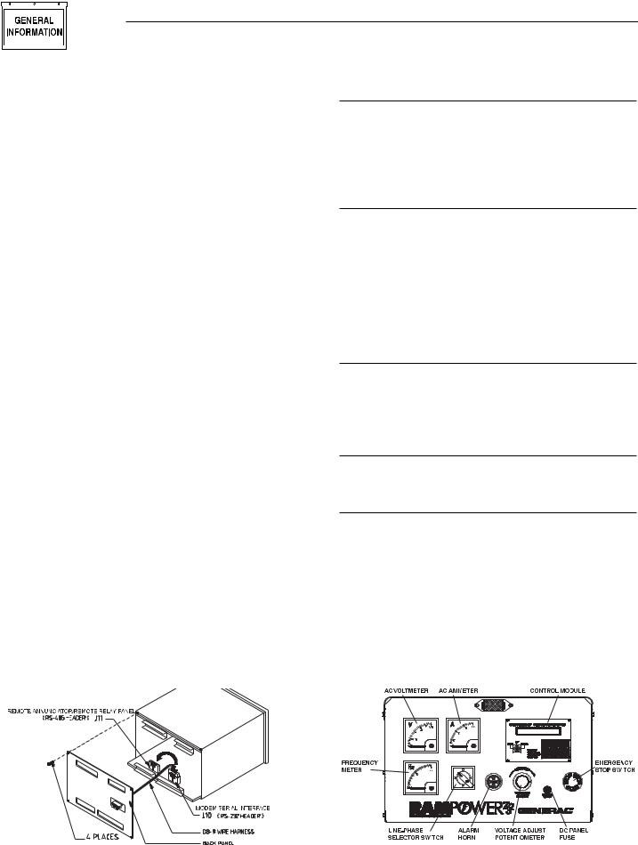
ADDITIONAL PANEL COMPONENTS
In addition to the control module, the E option panel contains the following components (see Figure 1.6):
AC VOLTMETER
This meter indicates the generator AC output voltage. To determine the nominal rated AC voltage of the unit, refer to the unit’s data plate.
NOTE:
Some generators are re-connectable to a variety of voltages. Some units may be equipped with a rotary “Voltage Selector Switch.” Be sure to read the “Generator AC Lead Connections” section in the Owner’s Manual.
AC AMMETER
This meter indicates the current draw of connected electrical loads, in amps. Also see “Line-phase Selector Switch.” For continuous operation, never exceed the rated maximum continuous current capacity of the generator.
FREQUENCY METER
This meter indicates the generator’s AC output frequency in “Hertz” (cycles per second).
LINE-PHASE SELECTOR SWITCH
This four-position switch permits selection of either line-to-line or line-to-neutral readings on the panel voltmeter and ammeter. Switch positions are as follows:
Switch |
Single-phase Units |
Three-phase units |
1 |
Line E1 to Neutral |
Line E1 to E2 |
2 |
Line E3 to Neutral |
Line E2 to E3 |
3 |
Line E1 to E3 |
Line E3 to E1 |
OFF |
No Reading |
No Reading |
|
|
|
Figure 1.5 – E Panel Serial Communications |
Figure 1.6 – E Option Panel Components |
||||||||||
|
|
|
Setup Modification |
||||||||
|
|
|
|
|
|
|
|
|
|||
|
|
|
|
|
|
|
|
|
|
|
|
|
|
|
|
|
|
|
|
|
|
|
|
|
|
|
|
|
|
|
|
|
|
|
|
|
|
|
|
|
|
|
|
|
|
|
|
|
|
|
|
|
|
|
|
|
|
|
|
|
|
|
|
|
|
|
|
|
|
|
|
|
|
|
|
|
|
|
|
|
|
|
|
|
|
|
|
|
|
|
|
|
|
|
|
|
|
|
|
|
|
|
|
|
|
|
|
|
|
|
|
|
|
|
|
|
|
|
|
|
|
|
|
|
|
|
|
|
|
|
|
|
|
|
|
|
|
|
|
|
|
|
|
10 Generac® Power Systems, Inc.

Section 1 — General Information
VOLTAGE ADJUST POTENTIOMETER
This potentiometer permits the operator to “fine adjust” the generator’s AC output voltage on units rated below 400 kW. Adjustment range is plus or minus five percent. Turn the knob clockwise to increase voltage, counterclockwise to decrease voltage.
ALARM HORN
This horn sounds an audible warning when an alarm condition exists. See the “Alarms” section for further information.
DC PANEL FUSE
This 15-amp fuse protects the panel components. This fuse is not to be confused with the control module internal fuse discussed in “Checking/Replacing the E Panel Control Module Internal Fuse.”
EMERGENCY STOP SWITCH
When pressed, this switch will automatically shut down the entire generator set. The operator must pull the switch out to its original position to reset it and allow for generator operation.
CHECKING/REPLACING THE E PANEL CONTROL MODULE INTERNAL FUSE
Typically, the main indication of fuse failure is the absence of any illuminated front panel LEDs (even with the key in the OFF position, the “Power” LED will be illuminated) and no text visible on the module display. It should be noted however, that these conditions can exist if either:
a.The generator start battery is dead (less than five volts) or disconnected.
b.The main panel fuse (15 amp) is blown.
c.The battery supply wires (#13 and #0) to the panel control module are open circuit (disconnected).
d.The “Power” connector (CON4) is disconnected from the rear of the control module.
e.The generator start battery connections have been reversed. Reversal of the battery connections WILL blow the internal fuse and is the most likely reason for its failure.
Before removing or disconnecting the E panel control module, check that none of the above conditions (a- e) exist.
If you are satisfied that the problem lies with the control module:
1.Disconnect the generator start battery.
2.Unplug all four wire harnesses from the back of the control module.
3.Loosen, then detach, the two retaining clips securing the control module and remove the module.
E Option Control Panels
4.Using a multimeter (e.g., Fluke 87) set to the diode range, measure between pins 1 (BAT+) and 2 (BAT- ) of connector CON4 on the module.
•With the positive meter lead connected to pin 2 and the negative lead to pin 1, the meter should read between 0.4 and 0.6 volts, which indicates that the internal fuse is OK.
•Reversing the meter leads would give a slowly increasing voltage reading on the meter, which also indicates a good fuse.
•An open circuit fuse will give an open circuit meter reading (.OL on Fluke 87).
If the meter reads open circuit:
5.Remove the four phillips head screws retaining the rear cover of the control module.
3.Open the back of the control module.
4.Locate the internal printed-circuit board mounted fuse, which is behind and to the left of CON4.
5.Remove the white plastic cover from the fuse holder and remove the fuse.
6.If the fuse has blown, replace the fuse (part #0A5705), reassemble the control module, and reinstall the control module and its connections.
7.Reconnect the generator start battery and check if the control module now functions.
If the fuse blows again, or was not blown when the module was opened, or the module still does not function, the E panel control module must be replaced.
USER PROGRAMMABLE INPUTS
The E panel has eight (8) user programmable inputs. These inputs can be used for annunciation, prealarm, or shutdown alarms. Four of the inputs, Battery Charge Fail, Gen Power, Line Power, and Programmable Input 4 are set up to annunciate on the control panel display and at the optional 20 Light Remote Annunciator (Programmable Input 4 will light the unlabeled “spare” LED). These four inputs can be used for other connections if a remote annunciator is not used. The other four inputs, if utilized, will annunciate at the control panel only.
The user programmable input connection points are located inside the E option control panel on a 12position strip labeled TB3 (refer to Figures 1.7 and 1.8 on page 12.). The first four terminals are labeled “prog input gnd”. These are the common ground connection points for the user supplied switch devices to be used for the programmable annunciation.
NOTE:
These ground terminals are for user programmable input use only. The are not to be used for grounding any other circuits.
Generac® Power Systems, Inc. 11

Section 1 — General Information
E Option Control Panels
Figure 1.7 — TB3 Units Up to 400 kW
Figure 1.8 — TB3 Units Over 400 kW
The remaining eight terminals on TB3 are for the “positive” side of each user programmable input switch circuit. These eight terminals have a five VDC potential available in an open-circuit condition (whether the control panel key switch is in the off, manual, or auto position). The inputs can be programmed to annunciate upon either an open circuit condition (five VDC potential at the terminal) or a grounded condition (zero VDC potential at the terminal). This voltage state is determined by the user supplied switch either opening or closing to cause an annunciation.
Program set-up for the user programmable inputs is carried out in the Digital I/O Menu of the E module (please refer to the Display Map on pages 18-19). Each of the eight inputs has four parameters in which specific options must be selected to make the annunciation function properly. These four parameters are labeled Input Channel Message, Input Channel Setting, Input Channel Alarm Enable, and Input Channel Alarm Type. Following is a brief description of each:
•Input Channel Message — for selecting letters and numbers to spell out what the display will read upon activation of that specific input.
•Input Channel Setting — for selecting whether annunciation should activate upon that specific circuit opening or closing to ground.
•Input Channel Alarm Enable — for enabling or disabling annunciation function of that specific input. Also, if enabled, for selecting when annunciation will be active. The choices are: Disabled, Always, Immediate and Hold-off. See E Control Panel Definitions on page 38.
•Input Channel Alarm Type — for selecting the type of alarm annunciation and the effect it has on the generators control system. The four choices are: Status, Non-latched, Latched and Shutdown. See E Control Panel Definitions on page 14.
WIRING EXAMPLES
USER PROGRAMMABLE INPUT NUMBER 1
On units rated below 400 kW, input number 1 is programmed for “Battery Charge Fail” annunciation at the control panel display, and the LED on the 20 Light Remote Annunciator (if used). A user supplied AC relay is wired in to be powered up by AC voltage that supplies the unit Battery Charger (see Figure 1.9).
Figure 1.9 — Battery Charge Fail Wiring
12 Generac® Power Systems, Inc.

Section 1 — General Information
E Option Control Panels
Upon loss of this AC supply voltage, the relay will deenergize. The normally closed contacts on the relay are to be connected to TB3 in the control panel. One wire connects to any of the four “Prog Input Gnd” terminals, the other wire connects to terminal number 5 (B/C Fail). With the relay de-energized, terminal 5 will be grounded, signaling the E module to activate on Programmable Input 1.
USER PROGRAMMABLE INPUTS NUMBERS 2 AND 3
On units rated below 400 kW, input numbers 2 and 3 are programmed for “Gen Power” and “Line Power” respectively, indicating the transfer switch position (Standby or Utility). Annunciation will occur at the control panel display and at the Remote Annunciator (if used). These signals will come from a set of spare auxiliary contacts located on the main contactor assembly in the transfer switch. The auxiliary contact switch is a set of dry contacts with three terminals: Common, Normally Open, and Normally Closed. Wires must be connected to these three terminals and routed to the generator control panel. These three wires must not be run in the same conduit as the generator’s main output conductors. The wire connected to the Common terminal on the auxiliary contacts will connect to any of the Prog Input Gnd terminals on TB3. The wire connected to the Normally Open terminal on the auxiliary contacts will connect to terminal 6 (Gen Power) on TB3. The wire connected to the Normally Closed terminal on the auxiliary contacts will connect to terminal 7 (Line Power) on TB3.
ALL USER PROGRAMMABLE INPUTS
On units rated below 400 kW, input numbers 4 through 8, and units rated over 400 kW, input numbers 1 through 8 can be used for virtually any kind of annunciation the user wishes to set up, within the parameters previously described, via an opened or closed switch device. Proper wiring consists of two wires from the user supplied switch: one wire connects to one of the “Prg Inpt Gnd” terminals (1 through 4 on TB3), the other wire connects to a Programmable Input terminal on TB3.
PROGRAMMING EXAMPLES
USER PROGRAMMABLE INPUT NUMBER 1
To be used for Battery Charge Fail annunciation. After properly wiring the circuit as described in Wiring Examples, program as follows:
1.Power up the E panel by connecting unit battery (ies) and inserting control panel fuse. The module will run through a self-test mode. Once it has completed its self-test, it will display the generator status (Stopped, ready to run).
2.Use the LEFT or RIGHT arrow keys to scroll over to the PARAMETER ENTRY column.
3.Once at the PARAMETER ENTRY column, press ENTER. Enter the password (if different from the factory set password 000000) and press ENTER. From the ENGINE PARAMETER MENU, press the RIGHT arrow to get to the DIGITAL I/O MENU.
4.Using the UP or DOWN arrows (the column is a continuous loop), scroll to INPUT CHANNEL 1 MESSAGE and press ENTER. Up to 24 letters, numbers and other characters can be entered to spell out what will be displayed upon this input becoming active. In this case, enter Battery Charge Fail. After entering the message, press ENTER.
5.Press the UP arrow to display INPUT CHANNEL 1 SETTING. Press ENTER, the display will read Input Function, OPEN=ALARM. The Battery Charge Fail annunciation should occur upon the user supplied relay de-energizing and its normal- ly-closed contact closing, therefore, select CLOSED=ALARM by pressing the UP or DOWN arrow. Press ENTER, the display will read Input Channel 1 Setting, CLOSED=ALARM.
6.Press the UP arrow, the display will read Input 1 Alarm Enable, DISABLED, press ENTER. The choices are DISABLED, ALWAYS, IMMEDIATE, and HOLD OFF. This alarm should always be active, therefore, scroll up or down and select ALWAYS, and press ENTER.
7.Press the UP arrow, the display will read Input Channel 1 Alarm Type, STATUS MESSAGE, press ENTER. The choices are STATUS MESSAGE, NON LATCHING ALARM, LATCHING ALARM and SHUTDOWN ALARM. This annunciation for Battery Charge Fail should be a STATUS message, therefore, scroll up or down and select STATUS MESSAGE by pressing ENTER.
Programming for User Input Channel 1, Battery Charge Fail is now complete. The E module has been programmed for a STATUS alarm message that is ALWAYS active. Upon loss of AC supply voltage to the generators battery charger, the user supplied relay will de-energize, its normally closed contacts will close, grounding TB3 terminal 5 to Prg Input Gnd. The E module will display BATTERY CHARGE FAIL. Because it was programmed as a STATUS alarm and not a LATCHING or SHUTDOWN alarm, the status message will clear when AC power is restored to the battery charger.
NOTE:
The Battery Charger Fail LED on the 20 Light Remote Annunciator (if connected) will also turn on when Input Channel 1 is activated.
Generac® Power Systems, Inc. 13

Section 2 — Operation
E Option Control Panels
OUTPUT FUNCTION TABLE
|
Output |
Function Name |
Description |
|
|
Function ID |
|
|
|
|
00 |
Output Disabled |
Output not in use |
|
|
01 |
Common Alarm |
Active for all latched, non-latched and shutdown alarms |
|
|
02 |
Low Oil Pressure Warning |
Active after hold off time |
|
|
03 |
Oil Pressure Shutdown |
Active after hold off time, low oil pressure |
|
|
04 |
High Coolant Temp. Warning |
Active after hold off time |
|
|
05 |
Coolant Temp. Shutdown |
Active after hold off time, high coolant temperature |
|
|
06 |
Low Coolant Temp. Alarm |
|
|
|
07 |
High Oil Temp. Warning |
|
|
|
08 |
Oil Temp. Shutdown |
High oil temperature |
|
|
09 |
Low Battery Voltage |
Must be below set value for five minutes |
|
|
10 |
High Battery Voltage |
|
|
|
11 |
Overspeed Shutdown |
|
|
|
12 |
Underspeed Alarm |
Active after hold off time |
|
|
13 |
Over Voltage Alarm |
Active after hold off time |
|
|
14 |
Under Voltage Alarm |
Active after hold off time |
|
|
15 |
Over Frequency Alarm |
Active after hold off time |
|
|
16 |
Under Frequency Alarm |
Active after hold off time |
|
|
17 |
High Fuel Alarm |
Above the warning set-point |
|
|
18 |
Low Fuel Alarm |
Below the warning set-point |
|
|
19 |
Low Fuel & Shutdown |
Below the shutdown set-point |
|
|
20 |
Failed to Start Alarm |
Overcrank |
|
|
21 |
Coolant Level Alarm |
Low coolant level |
|
|
22 |
RPM Sensor Failed Alarm |
Magnetic pickup failure |
|
|
23 |
Start Inhibit Alarm |
Oil pressure was present at start request |
|
|
24 |
Emergency Stop Alarm |
Emergency stop active |
|
|
25 |
Oil Press. Sense Fault |
Sensor is either open or short circuit |
|
|
26 |
Oil Temp. Sense Fault |
Sensor is either open or short circuit |
|
|
27 |
Coolant Temp. Sense Fault |
Sensor is either open or short circuit |
|
|
28 |
Analog Channel 1 High |
Input at user analog channel 1 is above programmed high set-point |
|
|
29 |
Analog Channel 1 Low |
Input at user analog channel 1 is below programmed low set-point |
|
|
30 |
Analog Channel 2 High |
Input at user analog channel 2 is above programmed high set-point |
|
|
31 |
Analog Channel 2 Low |
Input at user analog channel 2 is below programmed low set-point |
|
|
32 |
Digital Channel 1 Active |
User programmable digital input 1 is active |
|
|
33 |
Digital Channel 2 Active |
User programmable digital input 2 is active |
|
|
34 |
Digital Channel 3 Active |
User programmable digital input 3 is active |
|
|
35 |
Digital Channel 4 Active |
User programmable digital input 4 is active |
|
|
36 |
Digital Channel 5 Active |
User programmable digital input 5 is active |
|
|
37 |
Digital Channel 6 Active |
User programmable digital input 6 is active |
|
|
38 |
Digital Channel 7 Active |
User programmable digital input 7 is active |
|
|
39 |
Digital Channel 8 Active |
User programmable digital input 8 is active |
|
|
40 |
Generator in Auto |
Key switch in auto position |
|
|
41 |
Generator in Manual |
Key switch in manual position |
|
|
42 |
Generator Off |
Key switch in off position |
|
|
43 |
Stopped |
Generator stopped |
|
|
44 |
Shutdown Due to Alarm |
Generator shutdown |
|
|
45 |
Stopped Ready to Run |
Generator ready to start |
|
|
46 |
Running |
Generator running |
|
|
47 |
Ready to Accept Load |
Generator has reached load accept voltage and frequency set-points, and |
|
|
|
|
the warm-up timer has expired |
|
|
48 |
All Alarms Active |
Generator running |
|
|
|
|
|
|
14 Generac® Power Systems, Inc.

Section 2 — Operation
E Option Control Panels
E PANEL MASTER CONTROL BOX CONFIGURATION SETTINGS
ENGINE PARAMETER MENU
Parameter |
|
Value |
|
|
|
Units |
|
RS232 Port |
|
Connection Mode (C1) |
|
|
|||
or RS485 Port |
|
Direct Connection Only |
|
|
|||
Restore All Values to |
|
Master Password |
|
|
|||
Default Settings |
|
Required (Factory Only) |
|
|
|||
Voltage Scaling Factor |
|
.05 |
to |
300 |
|
|
|
Flywheel Teeth |
|
30 |
to |
200 |
|
Number |
|
Panel I.D. |
|
000000 |
to |
999999 |
|
|
|
User Password |
|
000000 |
to |
999999 |
|
|
|
Preheat Option |
|
|
|
(P1) |
|
|
|
Load Accept Frequency |
|
0 |
|
to |
90 |
|
Hz |
Load Accept Voltage |
|
0 |
|
to |
2000 |
|
V |
Starter Disengage Speed |
|
0 |
|
to |
4000 |
|
RPM |
Number of Start Attempts |
|
0 |
|
to |
10 |
|
Number |
Generator Cool Down Time |
|
0 |
|
to |
600 |
|
min. |
Generator Warm Up Time |
|
0 |
|
to |
600 |
|
sec. |
Alarm Hold Off Time |
|
0 |
|
to |
15 |
|
sec. |
Start Attempt Pause Time |
|
5 |
|
to |
600 |
|
sec. |
Start Timer |
|
3 |
|
to |
15 |
|
sec. |
Preheat Timer |
|
0 |
|
to |
30 |
|
sec. |
|
|
|
|||||
Available Options: P1 = No Preheat, Before Start, Before and During Start |
|||||||
|
C1 |
= Direct Connection, Modem Connection, Modem Connection & Setup |
|||||
SYSTEM ALARM MENU
Parameter |
Value |
|
|
Units |
Active |
|
Type |
||
Low Fuel Shutdown Alarm |
0 |
to |
100 |
% |
|
|
(A2) |
|
Shutdown Alarm |
Fuel Level Low Warning |
0 |
to |
100 |
% |
|
|
(A2) |
|
Non-latching Alarm |
|
|
|
|
|
|
|
(A2) |
|
|
Fuel Level High Warning |
0 |
to |
100 |
% |
|
|
|
Non-latching Alarm |
|
Under Freq. |
0 |
to |
100 |
Hz |
|
|
|
|
|
|
Hold Off |
|
(T1) |
||||||
Over Freq. |
0 |
to |
100 |
Hz |
Hold Off |
|
(T1) |
||
Under Voltage |
0 |
to |
2000 |
V |
Hold Off |
|
(T1) |
||
Over Voltage |
0 |
to |
2000 |
V |
Hold Off |
|
(T1) |
||
Engine Underspeed Alarm |
0 |
to |
4500 |
RPM |
Hold Off |
|
(T1) |
||
Engine Overspeed Alarm |
1000 |
to |
4500 |
RPM |
Immediate |
|
|
||
|
Shutdown Alarm |
||||||||
Battery Volts High Warning |
4 |
to |
30 |
V |
Always |
|
Non-latching Alarm |
||
Battery Volts Low Warning |
4 |
to |
30 |
V |
Always |
|
Non-latching Alarm |
||
|
-5 |
to |
275 |
|
|
|
|
||
Oil Temp. Shutdown Alarm |
Deg. F |
|
|
(A1) |
|
Shutdown Alarm |
|||
Oil Temp. Warning |
-5 |
to |
275 |
Deg. F |
|
|
(A1) |
|
Non-latching Alarm |
Coolant Temp. Shutdown Alarm |
-5 |
to |
275 |
Deg. F |
|
|
|
|
Shutdown Alarm |
|
|
Hold Off |
|
||||||
Coolant Temp. High Warning |
-5 |
to |
275 |
Deg. F |
Hold Off |
|
Non-latching Alarm |
||
Coolant Temp. Low Warning |
0 |
to |
245 |
Deg. F |
Always |
|
Non-latching Alarm |
||
Oil Press. Shutdown Alarm |
0 |
to |
100 |
PSI |
Hold Off |
|
Shutdown Alarm |
||
Oil Press. Warning |
0 |
to |
100 |
PSI |
Hold Off |
|
Non-latching Alarm |
||
Available Options: A1 = Disable, Hold off, Immediate
A2 = Disable, Always
T1 = Shutdown Alarm, Latching Alarm, Non-latching Alarm, Status Message
Generac® Power Systems, Inc. 15

Section 2 — Operation
E Option Control Panels
DIGITAL I/O MENU
Channel |
|
Message |
Setting |
Alarm Enable |
Alarm Type |
|
Output 1 |
|
|
|
(F1) |
|
|
Output 2 |
|
|
|
(F1) |
|
|
Output 3 |
|
|
|
(F1) |
|
|
Preheat Output Function |
|
|
|
(F1) |
|
|
User Input 1 |
*1 |
Battery Charge Fail |
|
(S1) |
(A1) |
(T1) |
User Input 2 |
*1 |
Generator Power |
|
(S1) |
(A1) |
(T1) |
User Input 3 |
*1 |
Line Power |
|
(S1) |
(A1) |
(T1) |
User Input 4 |
*2 |
Backup Low Oil Pressure |
|
(S1) |
(A1) |
(T1) |
User Input 5 |
*2 |
Backup High Engine Temp. |
|
(S1) |
(A1) |
(T1) |
User Input 6 |
*2 |
Oil Filter Blocked |
|
(S1) |
(A1) |
(T1) |
User Input 7 |
*2 |
MLCB |
|
(S1) |
(A1) |
(T1) |
User Input 8 |
*2 |
Ruptured Tank |
|
(S1) |
(A1) |
(T1) |
Messages can be a maximum of 24 characters including spaces. |
|
|
|
|||
Available Options: A1 = Disabled, Hold Off, Immediate, Always |
|
|
||||
|
|
F1 = See output function table for available options. |
|
|||
|
|
S1 = Closed (Low Signal/Contact Closure to Ground), Open (High signal/Open Circuit) |
||||
|
|
T1 = Shutdown Alarm, Latching Alarm, Non-latching alarm, Status Message |
||||
*1 Assigned if used with 20 light Remote Annunciator or Remote Relay Panel Otherwise available for any customer options.
*2 Factory wired if unit is equipped with these options. Otherwise these inputs are available for any customer requirements.
ANALOG INPUT MENU
|
|
|
|
Alarm Msg. |
|
|
(Alarm) |
(Alarm) |
||||
|
Value at |
Value at |
(Display) |
Message |
Setpoint |
Enable |
Type |
|
||||
|
0V |
10V |
Title |
High |
Low |
High Low |
High |
Low |
High |
Low |
||
Analog Channel 1 |
|
|
|
|
|
|
|
(A1) |
(A1) |
(T1) |
|
(T1) |
Analog Channel 1 |
|
|
|
|
|
|
|
(A1) |
(A1) |
(T1) |
|
(T1) |
Messages can be a maximum of 24 characters including spaces.
Available Options: A1 = Disabled, Hold Off, Immediate, Always
T1 = Shutdown Alarm, Latching Alarm, Non-latching alarm, Status Message
16 Generac® Power Systems, Inc.

Section 2 — Operation
E Option Control Panels
GenLink® Communications Flowchart
TABLE A
Dip Switch |
Setting |
|
|
|
|
|
|
|
|
|
|
|
|
|
|
|
|
|
|
|
|
|
|
|
|
|
|
|
|
|
|
|
|
|
|
|
|
|
|
|||||||
1 |
|
Up |
|
|
|
|
|
|
|
|
|
|
|
|
|
|
|
|
|
|
|
|
|
|
|
|
|
|
|
|
|
|
|
|
|
|
|
|
|
|||||||
2 |
|
Down |
|
|
|
|
|
|
|
|
|
|
|
|
|
|
|
|
|
|
|
|
|
|
|
|
|
|
|
|
|
|
|
|
|
|
|
|
|
|||||||
|
|
|
|
|
|
|
|
|
|
|
|
|
|
|
|
|
|
|
|
|
|
|
|
|
|
|
|
|
|
|
|
|
|
|
|
|
|
|
|
|||||||
3 |
|
Down |
|
|
|
|
|
|
|
|
|
|
|
|
|
|
|
|
|
|
|
|
|
|
|
|
|
|
|
|
|
|
|
|
|
|
|
|
|
|||||||
|
|
|
|
|
|
|
|
|
|
|
|
|
|
|
|
|
|
|
|
|
|
|
|
|
|
|
|
|
|
|
|
|
|
|
|
|
|
|
|
|||||||
4 |
|
Down |
|
|
|
|
|
|
|
|
|
|
|
|
|
|
|
|
|
|
|
|
|
|
|
|
|
|
|
|
|
|
|
|
|
|
|
|
|
|||||||
5 |
|
Up |
|
|
|
|
|
|
|
|
|
|
|
|
|
|
|
|
|
|
|
|
|
|
|
|
|
|
|
|
|
|
|
|
|
|
|
|
|
|
|
|||||
|
|
|
|
|
|
|
|
|
|
|
|
|
|
|
|
|
|
|
|
|
|
|
|
|
|
|
|
|
|
|
|
|
|
|
|
|
|
|
|
|||||||
6 |
|
Up |
|
|
|
|
|
|
|
|
|
|
|
|
|
|
|
|
|
|
|
|
|
|
|
|
|
|
|
|
|
|
|
|
|
|
|
|
|
|
|
|||||
|
|
|
|
|
|
|
|
|
|
|
|
|
|
|
|
|
|
|
|
|
|
|
|
|
|
|
|
|
|
|
|
|
|
|
|
|
|
|
|
|||||||
7 |
|
Up |
|
|
|
|
|
|
|
|
|
|
|
|
|
|
|
|
|
|
|
|
|
|
|
|
|
|
|
|
|
|
|
|
|
|
|
|
|
|
|
|||||
|
|
|
|
|
|
|
|
|
|
|
|
|
|
|
|
|
|
|
|
|
|
|
|
|
|
|
|
|
|
|
|
|
|
|
|
|
|
|
|
|||||||
8 |
|
Down |
|
|
|
|
|
|
|
|
|
|
|
|
|
|
|
|
|
|
|
|
|
|
|
|
|
|
|
|
|
|
|
|
|
|
|
|
|
|
|
|||||
|
|
|
|
|
|
|
|
|
|
|
|
|
|
|
|
|
|
|
|
|
|
|
|
|
|
|
|
|
|
|
|
|
|
|
|
|
|
|
|
|||||||
|
|
|
|
|
|
|
|
|
|
|
|
|
|
|
|
|
|
|
|
|
|
|
|
|
|
|
|
|
|
|
|
|
|
|
|
|
|
|
|
|
|
|
|
|
|
|
|
|
|
|
|
|
|
|
|
|
|
|
|
|
|
|
|
|
|
|
|
|
|
|
|
|
|
|
|
|
|
|
|
|
|
|
|
|
|
|
|
|
|
|
|
|
|
|
|
|
|
|
|
|
|
|
|
|
|
|
|
|
|
|
|
|
|
|
|
|
|
|
|
|
|
|
|
|
|
|
|
|
|
|
|
|
|
|
|
|
|
|
|
|
|
|
|
|
|
|
|
|
|
|
|
|
|
|
|
|
|
|
|
|
|
|
|
|
|
|
|
|
|
|
|
|
|
|
|
|
|
|
|
|
|
|
|
|
|
|
|
|
|
|
|
|
|
|
|
|
|
|
|
|
|
|
|
|
|
|
|
|
|
|
|
|
|
|
|
|
|
|
|
|
|
|
|
|
|
|
|
|
|
|
|
|
|
|
|
|
|
|
|
|
|
|
|
|
|
|
|
|
|
|
|
|
|
|
|
|
|
|
|
|
|
|
|
|
|
|
|
|
|
|
|
|
|
|
|
|
|
|
|
|
|
|
|
|
|
|
|
|
|
|
|
|
|
|
|
|
|
|
|
|
|
|
|
|
|
|
|
|
|
|
|
|
|
|
|
|
|
|
|
|
|
|
|
|
|
|
|
|
|
|
|
|
|
|
|
|
|
|
|
|
|
|
|
|
|
|
|
|
|
|
|
|
|
|
|
|
|
|
|
|
|
|
|
|
|
|
|
|
|
|
|
|
|
|
|
|
|
|
|
|
|
|
|
|
|
|
|
|
|
|
|
|
|
|
|
|
|
|
|
|
|
|
|
|
|
|
|
|
|
|
|
|
|
|
|
|
|
|
|
|
|
|
|
|
|
|
|
|
|
|
|
|
|
|
|
|
|
|
|
|
|
|
|
|
|
|
|
|
|
|
|
|
|
|
|
|
|
|
|
|
|
|
|
|
|
|
|
|
|
|
|
|
|
|
|
|
|
|
|
|
|
|
|
|
|
|
|
|
|
|
|
|
|
|
|
|
|
|
|
|
|
|
|
|
|
|
|
|
|
|
|
|
|
|
|
|
|
|
|
|
|
|
|
|
|
|
|
|
|
|
|
|
|
|
|
|
|
|
|
|
|
|
|
|
|
|
|
|
|
|
|
|
|
|
|
|
|
|
|
|
|
|
|
|
|
|
|
|
|
|
|
|
|
|
|
|
|
|
|
|
|
|
|
|
|
|
|
|
|
|
|
|
|
|
|
|
|
|
|
|
|
|
|
|
|
|
|
|
|
|
|
|
|
|
|
|
|
|
|
|
|
|
|
|
|
|
|
|
|
|
|
|
|
|
|
|
|
|
|
|
|
|
|
|
|
|
|
|
|
|
|
|
|
|
|
|
|
|
|
|
|
|
|
|
|
|
|
|
|
|
|
|
|
|
|
|
|
|
|
|
|
|
|
|
|
|
|
|
|
|
|
|
|
|
|
|
|
|
|
|
|
|
|
|
|
|
|
|
|
|
|
|
|
|
|
|
|
|
|
|
|
|
|
|
|
|
|
|
|
|
|
|
|
|
|
|
|
|
|
|
|
|
|
|
|
|
|
|
|
|
|
|
|
|
|
|
|
|
|
|
|
|
|
|
|
|
|
|
|
|
|
|
|
|
|
|
|
|
|
|
|
|
|
|
|
|
|
|
|
|
|
|
|
|
|
|
|
|
|
|
|
|
|
|
|
|
|
|
|
|
|
|
|
|
|
|
|
|
|
|
|
|
|
|
|
|
|
|
|
|
|
|
|
|
|
|
|
|
|
|
|
|
|
|
|
|
|
|
|
|
|
|
|
|
|
|
|
|
|
|
|
|
|
|
|
|
|
|
|
|
|
|
|
|
|
|
|
|
|
|
|
|
|
|
|
|
|
|
|
|
|
|
|
|
|
|
|
|
|
|
|
|
|
|
|
|
|
|
|
|
|
|
|
|
|
|
|
|
|
|
|
|
|
|
|
|
|
|
|
|
|
|
|
|
|
|
|
|
|
|
|
|
|
|
|
|
|
|
|
|
|
|
|
|
|
|
|
|
|
|
|
|
|
|
|
|
|
|
|
|
|
|
|
|
|
|
|
|
|
|
|
|
|
|
|
|
|
|
|
|
|
|
|
|
|
|
|
|
|
|
|
|
|
|
|
|
|
|
|
|
|
|
|
|
|
|
|
|
|
|
|
|
|
|
|
|
|
|
|
|
|
|
|
|
|
|
|
|
|
|
|
|
|
|
|
|
|
|
|
|
|
|
|
|
|
|
|
|
|
|
|
|
|
|
|
|
|
|
|
|
|
|
|
|
|
|
|
|
|
|
|
|
|
|
|
|
|
|
|
|
|
|
|
|
|
|
|
|
|
|
|
|
|
|
|
|
|
|
|
|
|
|
|
|
|
|
|
|
|
|
|
|
|
|
|
|
|
|
|
|
|
|
|
|
|
|
|
|
|
|
|
|
|
|
|
|
|
|
|
|
|
|
|
|
|
|
|
|
|
|
|
|
|
|
|
|
|
|
|
|
|
|
|
|
|
|
|
|
|
|
|
|
|
|
|
|
|
|
|
|
|
|
|
|
|
|
|
|
|
|
|
|
|
|
|
|
|
|
|
|
|
|
|
|
|
|
|
|
|
|
|
|
|
|
|
|
|
|
|
|
|
|
|
|
|
|
|
|
|
|
|
|
|
|
|
|
|
|
|
|
|
|
|
|
|
|
|
|
|
|
|
|
|
|
|
|
|
|
|
|
|
|
|
|
|
|
|
|
|
|
|
|
|
|
|
|
|
|
|
|
|
|
|
|
|
|
|
|
|
|
|
|
|
|
|
|
|
|
|
|
|
|
|
|
|
|
|
|
|
|
|
|
|
|
|
|
|
|
|
|
|
|
|
|
|
|
|
|
|
|
|
|
|
|
|
|
|
|
|
|
|
|
|
|
|
|
|
|
|
|
|
|
|
|
|
|
|
|
|
|
|
|
|
|
|
|
|
|
|
|
|
|
|
|
|
|
|
|
|
|
|
|
|
|
|
|
|
|
|
|
|
|
|
|
|
|
|
|
|
|
|
|
|
|
|
|
|
|
|
|
|
|
|
|
|
|
|
|
|
|
|
|
|
|
|
|
|
|
|
|
|
|
|
|
|
|
|
|
|
|
|
|
|
|
|
|
|
|
|
|
|
|
|
|
|
|
|
|
|
|
|
|
|
|
|
|
|
|
|
|
|
|
|
|
|
|
|
|
|
|
|
|
|
|
|
|
|
|
|
|
|
|
|
|
|
|
|
|
|
|
|
|
|
|
|
|
|
|
|
|
|
|
|
|
|
|
|
|
|
|
|
|
|
|
|
|
|
|
|
|
|
|
|
|
|
|
|
|
|
|
|
|
|
|
|
|
|
|
|
|
|
|
|
|
|
|
|
|
|
|
|
|
|
|
|
|
|
|
|
|
|
|
|
|
|
|
|
|
|
|
|
|
|
|
|
|
|
|
|
|
|
|
|
|
|
|
|
|
|
|
|
|
|
|
|
|
|
|
|
|
|
|
|
|
|
|
|
|
|
|
|
|
|
|
|
|
|
|
|
|
|
|
|
|
TABLE B
“E” Panel Pin |
Modem Pin |
|
1 |
8 |
|
2 |
3 |
|
3 |
2 |
|
4 |
20 |
|
5 |
7 |
|
|
|
|
Generac® Power Systems, Inc. 17

Power ®Generac 18 |
|
|
|
|
|
|
|
|
|
|
|
|
|
DISPLAY PANEL E |
Systems, |
|
|
|
|
|
|
E-PANEL DISPLAY MAP |
|
|
|
MAP |
|||
|
GENERATOR |
|
ALARM STATUS |
|
ALARM LOG |
|
INSTRUMENTATION |
|
PARAMETER ENTRY |
|
SOFTWARE VERSION |
|
GENERATOR COMMAND |
|
|
STATUS |
|
|
|
|
|
|
|
||||||
|
|
|
|
|
|
|
|
|
|
|
|
|
|
|
.Inc |
Stopped ready to run |
|
No active messages * |
|
Logged Alarm Number 1 |
|
Generator Voltage |
|
Parameter entry |
|
Generac digital panel |
|
Generator switch off |
|
|
|
|
|
|
|
XXX Volts |
|
Press Enter to Continue |
|
Software version X.XX |
|
Generator switch off |
|
|
|
Or |
Or |
* this is true as long as |
Or |
or |
Or |
or |
Or |
Enter |
Or |
Enter * |
Or |
Turn key to auto mode: |
Or |
|
|
|
there are no messages |
|
|
|
|
|
|
|
Generator in auto mode |
|
||
|
|
|
|
|
|
|
|
|
|
|
|
|
||
|
|
|
|
|
Thru |
|
Hours Run |
|
|
|
* Display test, |
|
stop command |
|
|
|
|
|
|
Logged Alarm Number 50 |
|
XXXXX.X Hrs |
|
|
|
all pixels black, all 4 LEDs |
|
Turn key to manual mode: |
|
|
|
|
|
|
|
|
or |
|
|
|
will be on |
|
Attempting to start |
|
|
|
|
|
|
|
|
|
Password |
|
|
|
Attempt number X |
|
|
|
|
|
|
|
|
|
|
|
|
|
|
|
||
|
|
|
|
|
|
|
Analog Input 2 |
|
XXXXXX |
|
|
|
|
|
|
|
|
|
|
|
|
X.X |
|
Enter |
|
|
|
|
|
|
|
|
|
|
|
|
or |
|
|
|
|
|
|
|
|
Analog Input 1 |
|
Engine Parameter Menu |
|
|
Or |
System Alarm Menu |
|
|
|
Or |
|
Digital I/O Menu |
|
|
|
Or |
|
Analog Input menu |
|||||||||||||||||||
|
X.X |
|
|
|
|
|
|
|
|
|
|
|
|
|
|
|
|
|
|
|
|
|
|
|
|
|
|
|
|
|
|
|
|
|
|
|
|
|
|
|
|
|
|
|
|
|
|
|
|
|
|
|
|
|
|
|
|
|
|
|
|
|
|
|
|
|
|
|
|
|
|
|
|
|
|
||
|
or |
|
|
|
or |
|
|
|
|
|
|
|
|
|
|
or |
|
|
|
|
|
|
|
|
|
or |
|
|
|
|
|
|
|
|
|
or |
|
|
|
|
|
|
|
|
|
|
|
|
|
|
|
|
|
|
|
|
|
|
|
|
|
|
|
|
|
|
|
|
|
|
|
|
|
|
|
|
|
|
Fuel Level |
|
|
|
|
|
|
|
|
|
|
|
|
Low Fuel Shutdown Enable |
|
|
|
|
|
|
|
|
Input Ch 8 Alarm Type |
|
|
|
|
|
|
|
Analog Ch 2 Low Type |
|||||||
|
X |
|
|
RS485 Port |
|
|
|
|
|
|
|
|
|
|
|
|
|
|
|
|
|
|
|
|
|
|
|
|
|
|
|
|
|
|
|
|
||
|
|
|
|
Direct Connection only |
|
|
|
|
|
|
|
|
|
|
|
|
|
|
|
|
|
|
|
|
|
|
|
|
|
|
|
|
|
|
|
|
||
|
or |
|
|
|
|
|
|
|
|
|
|
|
|
|
|
or |
|
|
|
|
|
|
|
|
|
or |
|
|
|
|
|
|
|
|
|
or |
|
|
|
|
or |
|
|
|
|
|
|
|
|
|
|
|
|
|
|
|
|
|
|
|
|
|
|
||||||||||||||
|
|
|
|
|
|
|
|
|
|
|
|
|
|
|
|
|
|
|
|
|
|
|
|
|
|
|
|
|
|
|
|
|
|
|
|
|
|
|
|
Battery Voltage |
|
|
RS 232 Port |
|
|
|
|
|
|
|
|
Low Fuel Shutdown Setpt |
|
|
|
|
|
|
|
|
Input Ch 8 Alarm enable |
|
|
|
|
|
|
|
Analog Ch 2 High Type |
||||||||
|
XX.X Volts |
|
Direct conection |
|
|
|
|
|
|
|
|
|
XX % |
|
|
|
|
|
|
|
|
|
|
|
|
|
|
|
|
|
|
|
|
|
||||
|
or |
|
|
|
or |
|
|
|
|
|
|
|
|
|
or |
|
|
|
|
|
|
|
|
|
or |
|
|
|
|
|
|
|
|
|
or |
|
||
|
|
|
|
|
|
|
|
|
|
|
|
|
|
|
|
|
|
|
|
|
|
|
|
|
|
|
|
|
|
|
|
|
|
|||||
|
|
RS 232 Port |
|
|
|
|
|
|
|
|
|
|
|
|
|
|
|
|
|
|
|
|
|
|
||||||||||||||
|
Oil Pressure |
|
Modem connection |
|
|
|
|
|
|
|
|
Fuel Level Low Enable |
|
|
|
|
|
|
|
|
Input Channel 8 Setting |
|
|
|
|
|
|
|
Analog Ch 2 Low Enable |
|||||||||
|
XXX p.s.I |
|
|
or |
|
|
|
|
|
|
|
|
|
|
|
|
|
|
|
|
|
|
|
|
|
|
|
|
|
|
|
|
|
|
|
|
||
|
or |
|
|
|
RS 232 Port |
|
|
|
|
|
|
|
|
|
or |
|
|
|
|
|
|
|
|
|
or |
|
|
|
|
|
|
|
|
|
or |
|
||
|
|
|
Modem connection & Setup |
|
|
|
|
|
|
|
|
|
|
|
|
|
|
|
|
|
|
|
|
|
|
|
|
|
|
|
|
|||||||
|
|
|
|
|
|
|
|
|
|
|
|
|
|
|
|
|
|
|
|
|
|
|
|
|
|
|
|
|
|
|
|
|
|
|
|
|||
|
Oil Temperature |
|
|
or |
|
|
|
|
|
|
|
|
|
Fuel Level Low Setpoint |
|
|
|
|
|
|
|
Input Channel 8 Message |
|
|
|
|
|
|
|
Analog Ch 2 High Enable |
||||||||
|
XXX deg F |
|
|
|
|
|
|
|
|
|
|
|
|
|
XX% |
|
|
|
|
|
|
|
|
|
|
|
|
|
|
|
|
|
|
|
|
|
||
|
or |
|
|
Restore all values |
|
|
|
|
|
|
|
|
|
or |
|
|
|
|
|
|
|
|
|
or |
|
|
|
|
|
|
|
|
|
or |
|
|||
|
|
|
|
to default settings |
|
|
|
|
|
|
|
|
|
|
|
|
|
|
|
|
|
|
|
|
|
|
|
|
|
|
|
|
|
|
|
|
||
Coolant Temperature |
|
|
or |
|
|
|
|
|
|
|
|
|
Fuel Level High Enable |
|
|
|
|
|
|
|
|
Input Ch 7 Alarm Type |
|
|
|
|
|
|
|
Analog Ch 2 low Setpoint |
||||||||
|
XXX deg. F |
|
|
|
|
|
|
|
|
|
|
|
|
|
|
|
|
|
|
|
|
|
|
|
|
|
|
|
|
|
|
|
|
|
X.X |
|||
|
or |
|
|
Voltage Scaling Factor |
|
|
|
|
|
|
|
|
|
or |
|
|
|
|
|
|
|
|
|
or |
|
|
|
|
|
|
|
|
|
or |
|
|||
|
|
|
|
|
XXX.XX |
|
|
|
|
|
|
|
|
|
|
|
|
|
|
|
|
|
|
|
|
|
|
|
|
|
|
|
|
|
|
|
|
|
|
Engine Speed |
|
|
or |
|
|
|
|
|
|
|
|
|
Fuel Level High Setpoint |
|
|
|
|
|
|
|
|
Input Ch 7 Alarm Enable |
|
|
|
|
|
|
|
Analog Ch 2 High Setpoint |
|||||||
|
XXXX Rpm |
|
|
|
|
|
|
|
|
|
|
|
|
|
XX% |
|
|
|
|
|
|
|
|
|
|
|
|
|
|
|
|
|
|
X.X |
||||
|
or |
|
|
|
Flywheel Teeth |
|
|
|
|
|
|
|
|
|
or |
|
|
|
|
|
|
|
|
|
or |
|
|
|
|
|
|
|
|
|
or |
|
||
|
|
|
|
|
XXX |
|
|
|
|
|
|
|
|
|
|
|
|
|
|
|
|
|
|
|
|
|
|
|
|
|
|
|
|
|
|
|
|
|
Generator Frequency |
|
|
or |
|
|
|
|
|
|
|
|
|
Under Freq Alarm Type |
|
|
|
|
|
|
|
|
Input Channel 7 Setting |
|
|
|
|
|
|
|
Analog 2 Low Alarm Msg |
||||||||
|
XX.XHz |
|
|
|
|
|
|
|
|
|
|
|
|
|
|
|
|
|
|
|
|
|
|
|
|
|
|
|
|
|
|
|
|
|
|
|
|
|
|
|
|
|
|
Panel I.D. |
|
|
|
|
|
|
|
|
|
or |
|
|
|
|
|
|
|
|
|
or |
|
|
|
|
|
|
|
|
|
or |
|
||
|
|
|
|
|
XXXXXX |
|
|
|
|
|
|
|
|
|
|
|
|
|
|
|
|
|
|
|
|
|
|
|
|
|
|
|
|
|
|
|
|
|
|
|
|
|
|
or |
|
|
|
|
|
|
|
|
|
Under Freq Setpoint |
|
|
|
|
|
|
|
Input Channel 7 Message |
|
|
|
|
|
|
|
Analog Ch 2 High Alarm Msg |
|||||||
|
|
|
|
|
|
|
|
|
|
|
|
|
|
|
|
XX.X Hz |
|
|
|
|
|
|
|
|
|
|
|
|
|
|
|
|
|
|
|
|
|
|
|
|
|
|
|
User Password |
|
|
|
|
|
|
|
|
|
or |
|
|
|
|
|
|
|
|
|
or |
|
|
|
|
|
|
|
|
|
or |
|
||
|
|
|
|
|
XXXXXX |
|
|
|
|
|
|
|
|
|
|
|
|
|
|
|
|
|
|
|
|
|
|
|
|
|
|
|
|
|
|
|
|
|
|
|
|
|
|
or |
|
|
|
|
|
|
|
|
|
Over Freq Alarm Type |
|
|
|
|
|
|
|
|
Input Ch 6 Alarm Type |
|
|
|
|
|
|
|
Analog Channel 2 Title |
||||||
|
|
|
|
|
|
|
|
|
|
|
|
|
|
|
|
|
|
|
|
|
|
|
|
|
|
|
|
|
|
|
|
|
|
|
|
|
|
|
|
|
|
|
|
Preheat Option |
|
|
|
|
|
|
|
|
|
or |
|
|
|
|
|
|
|
|
|
or |
|
|
|
|
|
|
|
|
|
or |
|
|
|
|
|
|
|
|
|
|
|
|
|
|
|
|
|
|
|
|
|
|
|
|
|
|
|
|
|
|
|
|
|
|
|
|
|
|
|
|
|
|
|
|
|
|
|
or |
|
|
|
|
|
|
|
|
|
Over Freq Setpoint |
|
|
|
|
|
|
|
|
Input Ch 6 Alarm enable |
|
|
|
|
|
|
|
Analog Ch 2 Value at 10V |
||||||
|
|
|
|
|
|
|
|
|
|
|
|
|
|
|
|
XX.X Hz |
|
|
|
|
|
|
|
|
|
|
|
|
|
|
|
|
|
|
X.X |
|||
|
|
|
|
Load Accept Frequency |
|
|
|
|
|
|
|
|
|
or |
|
|
|
|
|
|
|
|
|
or |
|
|
|
|
|
|
|
|
|
or |
|
|||
|
|
|
|
|
XX.X Hz |
|
|
|
|
|
|
|
|
|
|
|
|
|
|
|
|
|
|
|
|
|
|
|
|
|
|
|
|
|
|
|
|
|
|
|
|
|
|
or |
|
|
|
|
|
|
|
|
|
Under Voltage Alarm Type |
|
|
|
|
|
|
|
|
Input Channel 6 Setting |
|
|
|
|
|
|
|
Analog Ch 2 value at 0V |
||||||
|
|
|
|
|
|
|
|
|
|
|
|
|
|
|
|
|
|
|
|
|
|
|
|
|
|
|
|
|
|
|
|
|
|
|
|
X.X |
||
|
|
|
|
Load Accept Voltage |
|
|
|
|
|
|
|
|
|
or |
|
|
|
|
|
|
|
|
|
or |
|
|
|
|
|
|
|
|
|
or |
|
|||
|
|
|
|
|
XXX Volts |
|
|
|
|
|
|
|
|
|
|
|
|
|
|
|
|
|
|
|
|
|
|
|
|
|
|
|
|
|
|
|
|
|
|
|
|
|
|
or |
|
|
|
|
|
|
|
|
|
Under Voltage Setpoint |
|
|
|
|
|
|
|
Input Channel 6 Message |
|
|
|
|
|
|
|
Analog Ch 1 Low Type |
|||||||
|
|
|
|
|
|
|
|
|
|
|
|
|
|
|
|
XXX Volts |
|
|
|
|
|
|
|
|
|
|
|
|
|
|
|
|
|
|
|
|
|
|
|
|
|
|
Starter Disengage Speed |
|
|
|
|
|
|
|
|
|
or |
|
|
|
|
|
|
|
|
|
or |
|
|
|
|
|
|
|
|
|
or |
|
|||
|
|
|
|
|
XXX RPM |
|
|
|
|
|
|
|
|
|
|
|
|
|
|
|
|
|
|
|
|
|
|
|
|
|
|
|
|
|
|
|
|
|
|
|
|
|
|
or |
|
|
|
|
|
|
|
|
|
Over Voltage Alarm Type |
|
|
|
|
|
|
|
|
Input Ch 5 Alarm Type |
|
|
|
|
|
|
|
Analog Ch 1 High Type |
||||||
|
|
|
|
|
|
|
|
|
|
|
|
|
|
|
|
|
|
|
|
|
|
|
|
|
|
|
|
|
|
|
|
|
|
|
|
|
|
|
|
|
|
|
Number of Start Attempts |
|
|
|
|
|
|
|
|
|
or |
|
|
|
|
|
|
|
|
|
or |
|
|
|
|
|
|
|
|
|
or |
|
|||
|
|
|
|
|
X |
|
|
|
|
|
|
|
|
|
|
|
|
|
|
|
|
|
|
|
|
|
|
|
|
|
|
|
|
|
|
|
|
|
|
|
|
|
|
or |
|
|
|
|
|
|
|
|
|
Over Voltage Setpoint |
|
|
|
|
|
|
|
|
Input Ch 5 Alarm Enable |
|
|
|
|
|
|
|
Analog Ch 1 Low Enable |
||||||
|
|
|
|
|
|
|
|
|
|
|
|
|
|
|
|
XXX Volts |
|
|
|
|
|
|
|
|
|
|
|
|
|
|
|
|
|
|
|
|
|
|
|
|
|
|
Generator Cool Down Time |
|
|
|
|
|
|
|
|
|
or |
|
|
|
|
|
|
|
|
|
or |
|
|
|
|
|
|
|
|
|
or |
|
|||
|
|
|
|
|
X Min |
|
|
|
|
|
|
|
|
|
|
|
|
|
|
|
|
|
|
|
|
|
|
|
|
|
|
|
|
|||||
|
|
|
|
|
|
|
|
|
|
|
|
|
|
|
|
|
|
|
|
|
|
|
|
|
|
|
|
|
|
|
|
|
|
|
|
|
|
|
Option E |
Section |
Panels Control |
Operation — 2 |
|
|
.Inc Systems, Power ®Generac
or
Gen. Warm Up Time
XSec or 
Alarm Hold Off Time
XX Sec
or
Start Attempt Pause Time
XX Sec
or
Start Timer
XX Sec
or
Preheat Timer
XX Sec
Overspeed Shutdown Setpt |
|
|
|
|
|
|
Input Channel 5 Setting |
|
|
|
|
|
Analog Ch 1 High Enable |
|||||||||
|
XXXX Rpm |
|
|
|
|
|
|
|
|
|
|
|
|
|
|
|
|
|
|
|||
|
or |
|
|
|
|
|
|
|
|
|
or |
|
|
|
|
|
|
|
|
or |
|
|
|
|
|
|
|
|
|
|
|
|
|
|
|
||||||||||
|
|
|
|
|
|
|
|
|
|
|
|
|
|
|
|
|
|
|
|
|
|
|
Underspeed Alarm Type |
|
|
|
|
|
Input Channel 5 Message |
|
|
|
|
|
Analog Ch 1 low Setpoint |
||||||||||
|
|
|
|
|
|
|
|
|
|
|
|
|
|
|
|
|
|
|
|
X.X |
||
|
or |
|
|
|
|
|
|
|
|
|
or |
|
|
|
|
|
|
|
|
or |
|
|
|
|
|
|
|
|
|
|
|
|
|
|
|
|
|||||||||
|
|
|
|
|
|
|
|
|
|
|
|
|
|
|
|
|
|
|
|
|
|
|
Underspeed Alarm Setpt |
|
|
|
|
|
|
Input Ch 4 Alarm Type |
|
|
|
|
|
Analog Ch 1 High Setpoint |
|||||||||
|
XXXX Rpm |
|
|
|
|
|
|
|
|
|
|
|
|
|
|
|
X.X |
|||||
|
|
|
|
|
|
|
|
|
|
|
|
|
|
|
|
|
|
|
|
|
|
|
|
or |
|
|
|
|
|
|
|
|
|
or |
|
|
|
|
|
|
|
|
or |
|
|
|
|
|
|
|
|
|
|
|
|
|
|
|
|
|||||||||
|
|
|
|
|
|
|
|
|
|
|
|
|
|
|
|
|
|
|
|
|
|
|
Battery Volts High Setpt |
|
|
|
|
|
|
Input Ch 4 Alarm Enable |
|
|
|
|
|
Analog 1 Low Alarm Msg |
|||||||||
|
XX.X V |
|
|
|
|
|
|
|
|
|
|
|
|
|
|
|
|
|
|
|||
|
|
|
|
|
|
|
|
|
|
|
|
|
|
|
|
|
|
|
|
|
|
|
|
or |
|
|
|
|
|
|
|
|
|
or |
|
|
|
|
|
|
|
|
or |
|
|
|
|
|
|
|
|
|
|
|
|
|
|
|
|
|||||||||
|
|
|
|
|
|
|
|
|
|
|
|
|
|
|
|
|
|
|
|
|
|
|
Battery Volts Low Setpt |
|
|
|
|
|
|
Input Channel 4 Setting |
|
|
|
|
|
Analog Ch 1 High Alarm Msg |
|||||||||
|
XX.X V |
|
|
|
|
|
|
|
|
|
|
|
|
|
|
|
|
|
|
|||
|
or |
|
|
|
|
|
|
|
|
|
or |
|
|
|
|
|
|
|
|
or |
|
|
|
|
|
|
|
|
|
|
|
|
|
|
|
|
|||||||||
|
|
|
|
|
|
|
|
|
|
|
|
|
|
|
|
|
|
|
|
|
|
|
Coolant Temp low Setpt |
|
|
|
|
|
Input Channel 4 Message |
|
|
|
|
|
Analog Channel 1 Title |
||||||||||
|
XXX Deg F |
|
|
|
|
|
|
|
|
|
|
|
|
|
|
|
|
|
|
|||
|
or |
|
|
|
|
|
|
|
|
|
or |
|
|
|
|
|
|
|
|
or |
|
|
|
|
|
|
|
|
|
|
|
|
|
|
|
|
|||||||||
|
|
|
|
|
|
|
|
|
|
|
|
|
|
|
|
|
|
|
|
|
|
|
Coolant Temp Shutdn Setpt. |
|
|
|
|
|
|
Input Ch 3 Alarm Type |
|
|
|
|
|
Analog Ch 1 Value at 10V |
|||||||||
|
XXX Deg F |
|
|
|
|
|
|
|
|
|
|
|
|
|
|
|
X.X |
|||||
|
|
|
|
|
|
|
|
|
|
|
|
|
|
|
|
|
|
|
|
|
|
|
|
or |
|
|
|
|
|
|
|
|
|
or |
|
|
|
|
|
|
|
|
or |
|
|
|
|
|
|
|
|
|
|
|
|
|
|
|
|
|||||||||
|
|
|
|
|
|
|
|
|
|
|
|
|
|
|
|
|
|
|
|
|
|
|
Coolant Temp High Setpt |
|
|
|
|
|
|
Input Ch 3 Alarm Enable |
|
|
|
|
|
Analog Ch 1 value at 0V |
|||||||||
|
XXX Deg F |
|
|
|
|
|
|
|
|
|
|
|
|
|
|
|
X.X |
|||||
|
or |
|
|
|
|
|
|
|
|
|
or |
|
|
|
|
|
|
|
|
|
|
|
|
|
|
|
|
|
|
|
|
|
|
|
|
|
|
|
|
|
|
|
|||
|
|
|
|
|
|
|
|
|
|
|
|
|
|
|
|
|
|
|
|
|
|
|
Oil Temp Shutdown Enable |
|
|
|
|
|
|
Input Channel 3 Setting |
|
|
|
|
|
|
|
|
|
||||||
|
|
|
|
|
|
|
|
|
|
|
|
|
|
|
|
|
|
|
|
|
|
|
|
or |
|
|
|
|
|
|
|
|
|
or |
|
|
|
|
|
|
|
|
|
|
|
|
|
|
|
|
|
|
|
|
|
|
|
|
|
|
|
|
||||||
|
|
|
|
|
|
|
|
|
|
|
|
|
|
|
|
|
|
|
|
|
|
|
Oil Temp. Shutdown Setpt |
|
|
|
|
|
Input Channel 3 Message |
|
|
|
|
|
|
|
|
|
|||||||
|
XX Deg F |
|
|
|
|
|
|
|
|
|
|
|
|
|
|
|
|
|
|
|||
|
|
|
|
|
|
|
|
|
|
|
|
|
|
|
|
|
|
|
|
|
|
|
|
or |
|
|
|
|
|
|
|
|
|
or |
|
|
|
|
|
|
|
|
|
|
|
|
|
|
|
|
|
|
|
|
|
|
|
|
|
|
|
|
||||||
|
|
|
|
|
|
|
|
|
|
|
|
|
|
|
|
|
|
|
|
|
|
|
Oil Temp Warn Enable |
|
|
|
|
|
|
Input Ch 2 Alarm Type |
|
|
|
|
|
|
|
|
|
||||||
|
|
|
|
|
|
|
|
|
|
|
|
|
|
|
|
|
|
|
|
|
|
|
|
or |
|
|
|
|
|
|
|
|
|
or |
|
|
|
|
|
|
|
|
|
|
|
|
|
|
|
|
|
|
|
|
|
|
|
|
|
|
|
|
||||||
|
|
|
|
|
|
|
|
|
|
|
|
|
|
|
|
|
|
|
|
|
|
|
Oil Temp. Warn Setpt |
|
|
|
|
|
|
Input Ch 2 Alarm Enable |
|
|
|
|
|
|
|
|
|
||||||
|
XX Deg F |
|
|
|
|
|
|
|
|
|
|
|
|
|
|
|
|
|
|
|||
|
or |
|
|
|
|
|
|
|
|
or |
|
|
|
|
|
|
|
|
|
|
|
|
|
|
|
|
|
|
|
|
|
|
|
|
|
|
|
|
|
||||||
|
|
|
|
|
|
|
|
|
|
|
|
|
|
|
|
|
|
|
|
|
|
|
Oil Press Shutdown Setpt |
|
|
|
|
|
|
Input Channel 2 Setting |
|
|
|
|
|
|
|
|
|
||||||
|
XX Psi |
|
|
|
|
|
|
|
|
|
|
|
|
|
|
|
|
|
|
|||
|
|
|
|
|
|
|
|
|
|
|
|
|
|
|
|
|
|
|
|
|
|
|
|
or |
|
|
|
|
|
|
|
|
or |
|
|
|
|
|
|
|
|
|
|
|
|
|
|
|
|
|
|
|
|
|
|
|
|
|
|
|
|
|
||||||
|
|
|
|
|
|
|
|
|
|
|
|
|
|
|
|
|
|
|
|
|
|
|
Oil Press Warn Setpt |
|
|
|
|
|
Input Channel 2 Message |
|
|
|
|
|
|
|
|
|
|||||||
|
XX Psi |
|
|
|
|
|
|
|
|
|
|
|
|
|
|
|
|
|
|
|||
|
|
|
|
|
|
|
|
|
|
|
|
|
|
|
|
|
|
|
|
|
|
|
|
|
|
|
|
|
|
|
|
|
|
or |
|
|
|
|
|
|
|
|
|
|
|
|
|
|
|
|
|
|
|
|
|
|
|
|
|
|
|
|
|
|
|
|
|
|
|
|
|
|
|
|
|
|
|
|
|
Input Ch 1 Alarm Type |
|
|
|
|
|
|
|
|
|
||
|
|
|
|
|
|
|
|
|
|
|
|
|
|
|
|
|
|
|
|
|
|
|
|
|
|
|
|
|
|
|
|
|
|
or |
|
|
|
|
|
|
|
|
|
|
|
|
|
|
|
|
|
|
|
|
|
|
|
|
|
|
|
|
|
|
|
|
|
|
|
|
|
|
|
|
|
|
|
|
|
Input Ch 1 Alarm Enable |
|
|
|
|
|
|
|
|
|
||
|
|
|
|
|
|
|
|
|
|
|
|
|
|
|
|
|
|
|
|
|
|
|
|
|
|
|
|
|
|
|
|
|
|
or |
|
|
|
|
|
|
|
|
|
|
|
|
|
|
|
|
|
|
|
|
|
|
|
|
|
|
|
|
|
|
|
|
|
|
|
|
|
|
|
|
|
|
|
|
|
Input Channel 1 Setting |
|
|
|
|
|
|
|
|
|
||
|
|
|
|
|
|
|
|
|
|
|
|
|
|
|
|
|
|
|
|
|
|
|
|
|
|
|
|
|
|
|
|
|
|
or |
|
|
|
|
|
|
|
|
|
|
|
|
|
|
|
|
|
|
|
|
|
|
|
|
|
|
|
|
|
|
|
|
|
|
|
|
|
|
|
|
|
|
|
|
Input Channel 1 Message |
|
|
|
|
|
|
|
|
|
|||
|
|
|
|
|
|
|
|
|
|
|
|
|
|
|
|
|
|
|
|
|
|
|
|
|
|
|
|
|
|
|
|
|
|
or |
|
|
|
|
|
|
|
|
|
|
|
|
|
|
|
|
|
|
|
|
|
|
|
|
|
|
|
|
|
|
|
|
|
|
|
|
|
|
|
|
|
|
|
|
|
Preheat Output Function |
|
|
|
|
|
|
|
|
|
||
|
|
|
|
|
|
|
|
|
|
|
|
|
|
|
|
|
|
|
|
|
|
|
|
|
|
|
|
|
|
|
|
|
|
or |
|
|
|
|
|
|
|
|
|
|
|
|
|
|
|
|
|
|
|
|
|
|
|
|
|
|
|
|
|
|
|
|
|
|
|
|
|
|
|
|
|
|
|
|
|
Output 3 Function |
|
|
|
|
|
|
|
|
|
||
|
|
|
|
|
|
|
|
|
|
|
|
|
|
|
|
|
|
|
|
|
|
|
|
|
|
|
|
|
|
|
|
|
|
or |
|
|
|
|
|
|
|
|
|
|
|
|
|
|
|
|
|
|
|
|
|
|
|
|
|
|
|
|
|
|
|
|
|
|
|
|
|
|
|
|
|
|
|
|
|
Output 2 Function |
|
|
|
|
|
|
|
|
|
||
|
|
|
|
|
|
|
|
|
|
|
|
|
|
|
|
|
|
|
|
|
|
|
|
|
|
|
|
|
|
|
|
|
|
or |
|
|
|
|
|
|
|
|
|
|
|
|
|
|
|
|
|
|
|
|
|
|
|
|
|
|
|
|
|
|
|
|
|
|
|
|
|
|
|
|
|
|
|
|
|
Output 1 Function |
|
|
|
|
|
|
|
|
|
||
|
|
|
|
|
|
|
|
|
|
|
|
|
|
|
|
|
|
|
|
|
|
|
Panels Control Option E |
Operation — 2 Section |
19

Section 3 — Troubleshooting and Diagnosis
E Option Control Panels
OIL PRESSURE SENSING (Refer to Figure 3.1)
OVERVIEW
An analog Oil Pressure Sender (OPS) is used for monitoring the engine oil pressure. This sender allows the E panel to measure and display the Engine oil pressure.
Refer to the owners manual for the OPS part number and mounting location.
Wire number 69 is used to connect the OPS to the E Panel. The Ground for the OPS is made through the engine block.
The OPS is a resistive device, whose resistance changes based on engine oil pressure. The resistance of the sender results in a voltage being developed across the sender. As the oil pressure increases, the resistance will decrease, causing the voltage to decrease. This changing voltage is read by the E Panel and converted into the engine Oil Pressure.
The E Panel will monitor and display oil pressure anytime the DC input to the E Panel is present.
TROUBLESHOOTING
Prior to any troubleshooting, the oil pressure parameters programmed into the E Panel should be checked and verified. The oil pressure input has two different set points associated with it. They are:
Pre-Low Oil Pressure Warning: This is the warning set point. The generator's alarm will sound, but the generator will continue to run.
Critical Low Oil Pressure Alarm: This is the alarm set point. The generator will shut down and sound the alarm.
It is important to verify that these parameters are set correctly for the specific unit. Check the E Panel settings against the Generator setup sheet. If the generator setup sheet is not available, contact Generac's service department for the recommended settings.
Figure 3.1 — Oil Pressure Sender Connections
Oil Pressure Sender Connections
Refer to the unit's Wiring Diagram for specific connector locations
TESTING THE CONTROL PANEL
It is relatively easy to do a thorough test of the E Panel's Oil Pressure input.
Place the Auto/Off/Manual switch to the Off position during this testing.
Open circuit testing
This test checks the high end of the oil pressure input of the E Panel.
1.Remove the 69 wire from the control panel terminal strip. This simulates a sender open circuit condition.
2.Look for the following response from the E Panel: The back light will flash, the Com Alarm LED will flash, and the display will read as follows:
OIL PRESS SENSE FAULT
PRESS ENTER TO ACCEPT
3.Press enter to accept the alarm.
Short circuit testing
This test checks the low end of the oil pressure input of the E Panel.
1.Reconnect the 69 wire to the control panel terminal strip.
Connect a jumper wire between the 69 and 0 positions on the control panel terminal strip. This simulates a sender short circuit condition
2.Look for the following response from the E Panel
2.1For units with software version V1.11 and earlier: The back light will flash, the Com Alarm LED will flash, and the display will read as follows:
OIL PRESS SENSE FAULT
PRESS ENTER TO ACCEPT
Press enter to accept the alarm.
2.2For units with software version V1.12 and later:
Use the arrow keys to go to the Oil pressure display screen.
The screen should display oil pressure as 125 p.s.i.
Control panel testing complete
E Panel |
|
E Panel |
|
|
|
+5V |
|
CON 2-5 |
|
|
|
Set Screw |
|
|
|||
|
|
|
|||
|
Connector |
|
|
||
|
69 |
|
69 |
69 |
|
|
|
|
|
|
Oil Pressure |
|
|
|
|
|
Sender |
|
69 Location on the |
69 Location in the |
|
(OPS) |
|
|
|
|
|||
|
Control Panel |
|
Deutsch Connector |
|
|
|
terminal strip |
|
("Sealed Connector" |
This Ground (0) |
|
|
|
|
Control Panels only) |
connection is |
|
|
|
|
|
|
made through the |
|
|
|
|
|
Engine Block |
1.Remove the jumper between the 69 and 0 locations on the control panel terminal strip.
2.If any E Panel alarms are present, press enter to accept.
Test Results
1.Tests 1and 2 Pass:
Move on to the next test "Testing the Oil Pressure Sender".
20 Generac® Power Systems, Inc.

Section 3 — Troubleshooting and Diagnosis
E Option Control Panels
2.If either test 1 or 2 failed:
2.1Repeat the open and short circuit testing directly at the back of the E Panel as follows: Open: The 69 wire should be removed from
CON2-5
Short: With the 69 wire still removed, insert a jumper wire into CON2-5. Connect the other end of the jumper to ground
(0).
After testing, remove the jumper wire from CON2-5 and insert the 69 wire back into CON2-5
2.2Test results:
2.2.1If these tests fail again directly at the back of the E Panel, then the E Panel has failed and should be replaced.
2.2.2If these tests pass at the back of the E Panel, but failed at the terminal strip, then there is a wiring error between the E Panel and the terminal strip. Check this wiring carefully.
TESTING THE OIL PRESSURE SENDER
The resistance of the OPS can be checked in a power down state as follows:
1.Remove the control panel fuse to power down the E panel.
2.Unplug CON2 from the E Panel.
3.Measure the resistance of the oil pressure sender. This measurement should be made between the sender terminal and the sender body.
The sender resistance should measure between 225 and 260 Ohms at 0 PSI.
NOTE:
If the engine has just been stopped, allow sufficient time for the oil pressure to drop to zero before making this measurement.
If the resistance measurement is not in this range, the sender has failed. Replace the sender.
If the resistance measurement is in this range, move on to the next test.
TESTING THE OIL PRESSURE SENDER CONNECTIONS
Visual Inspection
Carefully check the wiring between the oil pressure sender and the E Panel.
1.Check the 69 wire connection to the OPS.
1.1Check for a proper crimp on the lug.
1.2Check to see if the sender nut is tightened securely. Be careful not to over tighten the nut. If the nut is over tightened, the stud will break free and cause incorrect sender readings. This nut should be tightened to 14 to 18 inch pounds.
1.3Check for any environmental corrosion on the lug or the sender terminal. Generac recommends the following actions if corrosion is found:
1.3.1Replace the lug.
1.3.2Replace the sender if possible. If not possible, thoroughly remove all of the corrosion from the sender terminal.
1.3.3Protect the lug and sender terminal with an approved automotive dielectric grease.
2.Check the 69 wire in the Deutsch connector (only used on the "water tight connector" panels.)
2.1Refer to appendix A for information on the Deutsch connectors used.
2.2Refer to the unit's wire diagram for the 69 location in the Deutsch plug.
3.Check the 69 wire on the control panel terminal strip.
3.1Check for a proper crimp on both lugs.
3.2Check to see if both screws are tightened securely. These screws should be tightened to 12 inch pounds.
4.Check the 69 wire going into CON2 on the back of the E Panel.
4.1Check to see if the wire is stripped properly inside the green plug. The wire conductor should be trapped inside the metal wire clamp. The wire insulation should not be trapped inside the metal wire clamp.
4.2Check to see if the set screw is tightened securely, but do not over tighten. This screw should be set to 2 to 4 inch pounds.
5.Check for any wire damage along the entire run between the E Panel and the sender.
5.1Check for any areas along the wire with missing insulation. This could allow the 69 line to momentarily come into contact with ground causing a false shut down.
5.2Check to see if the wire is pinched anywhere along the run. A wire that is pinched between the sheet metal can cause the 69 wire to momentarily come into contact with ground resulting in a shut down fault. A pinched wire may also cause the wire to break inside the insulation. This could cause the 69 line to monetarily "open" while running. This will also result in a shut down fault.
Generac® Power Systems, Inc. 21

Section 3 — Troubleshooting and Diagnosis
E Option Control Panels
Check the OPS mounting
The ground return (0) connection for the OPS is made by the physical connection of the sender to the engine block. This connection may be made directly, or through a series of adapters or fittings.
Check for the following at each junction point:
1.Check for a tight mechanical connection.
2.Check for a good electrical connection.
Resistance measurement
The resistance of the OPS was measured in "Testing the Oil Pressure Sender."
In that test, the resistance was measured directly across the OPS. This test will now measure that same resistance inside the control panel. This will provide an additional test of the wiring and connections used to connect the sender to the control panel.
4.1.2.2Remove the OPS and check the conditions of the threads. Check for an excessive amount of pipe sealant on the threads. Ensure there is no pipe sealant on the end of the sender covering the oil inlet hole. Repeat step D, measuring the resistance between the 69 and 0 locations on the control panel terminal strip and comparing it to the earlier reading.
4.2If this measurement is less than 2-3 Ohms greater than the one taken directly across the OPS, and a thorough visual inspection was performed, the wiring is OK.
LOW COOLANT LEVEL (Refer to Figure 3.2)
1.Remove the control panel fuse to power down the E Panel.
2.Unplug CON2 from the E Panel.
3.Measure the resistance between the 69 and 0 locations on the control panel terminal strip.
4.Compare this measurement to the measurement taken directly across the OPS.
4.1If this measurement is more than 2-3 Ohms greater than the one taken directly across the OPS, there is a problem with the sender connections. You can determine if the problem is the 69 connection or the 0 connection as follows:
4.1.1Measure the resistance between the OPS stud and the 69 wire inside the control panel. If this measurement is greater than 2-3 Ohms, replace the entire wire running between the control panel and the OPS stud.
Repeat step D, measuring the resistance between the 69 and 0 locations on the control panel terminal strip and comparing it to the earlier reading.
4.1.2Measure the resistance between the body of the sender and the 0 location on the control panel terminal strip. If this measurement is greater than 2-3 Ohms, go back and carefully check the following:
4.1.2.1OPS mounting, including all fittings and adapters.
OVERVIEW
A Low Coolant Level (LCL) sensor is placed in the generator's coolant system. This sensor allows the E Panel to detect a Low Coolant Level condition.
Wire number 85 is used to connect the LCL to the E Panel. The Ground for the LCL is made through the radiator frame or engine block (depending on where the LCL is located). The LCL is a resistive device whose resistance changes based on the temperature of the LCL.
The resistance of the LCL results in a voltage being developed across the LCL. This voltage changes as the resistance changes. This changing voltage is read by the E Panel.
The LCL is supplied with current from the E Panel. This current will cause the LCL to generate heat. If the LCL is in coolant, the coolant will keep the LCL from heating up. If the LCL is in air, it will heat up telling the E panel there is a low coolant condition.
In most systems, a back up High Water Temperature (HWT) switch is wired in parallel with the LCL. This switch is a normally open switch whose contacts will close at a predetermined temperature setting. If this HWT switch closes, it will result in the E Panel shutting down with a "Low Coolant Level" display.
Refer to owners manual for the LCL and HWT part numbers and mounting locations.
The E Panel checks for low coolant level as follows:
Software version V1.03 and earlier: Will check for a low coolant level anytime the DC input to the E Panel is present.
Software version V1.04 and later: Will only check for a low coolant level once the engine has started and the hold off timer has expired.
There are no user-definable parameters for the Low Coolant Level.
22 Generac® Power Systems, Inc.
 Loading...