


04390-3
C
LISTE
D
U
S
Installation and
Owner’s Manual
Air-cooled, Prepackaged
Automatic Standby Generators
Models:
04389-3 (6 kW NG, 7 kW LP)
04456-3 (12 kW NG, 12 kW LP)
04390-3 (13 kW NG, 15 kW LP)
GENERAC
POWER SYSTEMS, INC.
Not intended for use as Primary Power in place of utility or in
life-support applications.
R
R
DANGER
DEADLY EXHAUST FUMES. OUTDOOR INSTALLATION ONLY!
INTRODUCTION
Thank you for purchasing this model of the Guardian
product line by Generac Power Systems Inc. This
model is a compact, high performance, air-cooled,
engine-driven generator designed to automatically
supply electrical power to operate critical loads during a utility power failure.
This unit is factory installed in an all-weather, metal
enclosure that is intended exclusively for outdoor installation. This generator will operate using either vapor
withdrawn liquid propane (LP) or natural gas (NG).
READ THIS MANUAL THOROUGHLY
If any portion of this manual is not understood, contact
the nearest Authorized Dealer for starting, operating
and servicing procedures.
Throughout this publication, and on tags and decals
affixed to the generator, DANGER, WARNING,
CAUTION and NOTE blocks are used to alert personnel to special instructions about a particular operation that may be hazardous if performed incorrectly
or carelessly. Observe them carefully. Their definitions are as follows:
DANGER
After this heading, read instructions that, if not
strictly complied with, will result in serious personal injury, including death, in addition to property
damage.
After this heading, read instructions that, if not
strictly complied with, may result in serious personal injury or property damage.
The operator is responsible for proper and safe use
of the equipment. The manufacturer strongly recommends that the operator read this Owner's Manual
and thoroughly understand all instructions before
using this equipment. The manufacturer also strongly recommends instructing other users to properly
start and operate the unit. This prepares them if they
need to operate the equipment in an emergency.
CONTENTS
This manual contains pertinent owner’s information,
including warranty, electrical diagrams, exploded
views and lists of repair parts, for three different
models:
• 04389-3 – 6 kW NG, 7 kW LP, single-cylinder GH410 Engine
• 04456-3 – 12 kW NG, 12 kW LP, V-twin GT-990
Engine
• 04390-3 – 13 kW NG, 15 kW LP, V-twin GT-990
Engine
OPERATION AND MAINTENANCE
It is the operator's responsibility to perform all safety
checks, to make sure that all maintenance for safe
operation is performed promptly, and to have the
equipment checked periodically by an Authorized
Dealer. Normal maintenance service and replacement
of parts are the responsibility of the owner/operator
and, as such, are not considered defects in materials
or workmanship within the terms of the warranty.
Individual operating habits and usage contribute to
the need for maintenance service.
Proper maintenance and care of the generator ensures
a minimum number of problems and keep operating
expenses at a minimum. See an Authorized Dealer
for service aids and accessories.
After this heading, read instructions that, if not
strictly complied with, could result in damage to
equipment and/or property.
NOTE:
After this heading, read explanatory statements
that require special emphasis.
These safety warnings cannot eliminate the hazards that they indicate. Common sense and strict
compliance with the special instructions while
performing the service are essential to preventing
accidents.
Four commonly used safety symbols accompany the
DANGER, WARNING and CAUTION blocks. The type
of information each indicates follows:
This symbol points out important safety infor-
mation that, if not followed, could endanger
personal safety and/or property of others.
This symbol points out potential explosion haz-
ard.
This symbol points out potential fire hazard.
This symbol points out potential electrical shock
hazard.
HOW TO OBTAIN SERVICE
When the generator requires servicing or repairs,
contact an Authorized Dealer for assistance. Service
technicians are factory-trained and are capable of
handling all service needs.
When contacting an Authorized Dealer about parts
and service, always supply the complete model number and serial number of the unit as given on its data
decal, which is located on the generator. See Figure 1.1
or Figure 1.2 in Section 1.6 for decal location.
Model No. ____________ Serial No. ______________
AUTHORIZED
DEALER LOCATION
To locate the nearest GUARDIAN AUTHORIZED
DEALER, please call this number:
1-800-333-1322
DEALER LOCATION INFORMATION
CAN BE OBTAINED AT THIS NUMBER or visit
www.guardiangenerators.com.

Table of Contents
Air-cooled 7 kW, 12 kW and 15 kW Generators
Introduction ........................Inside Front Cover
Read This Manual Thoroughly ........................ IFC
Contents .......................................................... IFC
Operation and Maintenance ............................ IFC
How to Obtain Service ..................................... IFC
Authorized Dealer Locator Number ................... IFC
Safety Rules ........................................................2
Standards Index ..................................................3
Section 1 – General Information ...................4
1.1 Unpacking/Inspection .................................... 4
1.2 Protection Systems ........................................4
1.3 NEC Requirement for Arc Fault Circuit
Interruption Breaker for Bedrooms ..............4
1.4 The Generator ...............................................5
1.5 Specifications ................................................ 6
1.6 System Set LED ............................................ 7
1.7 Fuel Requirements and Recommendations ... 7
1.8 Fuel Consumption ......................................... 7
1.9 Reconfiguring the Fuel System ...................... 7
1.10 Location ........................................................8
1.11 Battery Installation ........................................ 9
1.12 The Battery ...................................................9
Section 2 – Post Installation Start-up
and Adjustments .......................10
2.1 Before Initial Startup...................................10
2.2 Check Transfer Switch Operation ...............10
2.3 Electrical Checks ........................................10
2.4 Generator Tests Under Load ....................... 11
2.5 Checking Automatic Operation .................... 11
2.6 Adjusting the Regulator
(Natural Gas Only) ....................................... 12
2.7 Engine Governor Adjustment ...................... 13
2.8 Voltage Regulator Adjustment ...................... 14
Section 3 – Operation ....................................14
3.1 Break-in Procedure .....................................14
3.2 Using the Auto/Off/Manual Switch ............... 14
3.3 Automatic Transfer Operation ..................... 15
3.4 Sequence of Automatic Operation ...............15
3.5 Manual Transfer Operation .........................16
3.6 Setting the Exercise Timer .......................... 17
3.7 Protection Systems ...................................... 17
Section 4 – Maintenance ...............................18
4.1 Fuses ........................................................... 18
4.2 Checking the Engine Oil Level ..................... 18
4.3 Changing the Engine Oil .............................. 19
4.4 Changing the Oil Filter ................................ 19
4.5 Changing the Engine Air Cleaner .................19
4.6 Spark Plug(s) .............................................. 20
4.7 Battery Maintenance .................................... 20
4.8 Adjusting GH-410/GT-990/760
Valve Clearance ............................................ 21
4.9 Cooling System ...........................................21
4.10 Attention After Submersion .........................22
4.11 Corrosion Protection ................................... 22
4.12 Out of Service Procedure ............................. 22
4.13 Service Schedule ......................................... 23
Section 5 – Troubleshooting ........................ 24
5.1 Troubleshooting Guide ................................ 24
Section 6 – Notes ........................................... 25
Section 7 – Electrical Data ........................... 28
Section 8 – Exploded Views and
Parts Lists ................................... 42
Section 9 – Mounting Dimensions ............. 63
Section 10 – Warranty ................................... 64
1
IMPORTANT SAFETY INSTRUCTIONS
Air-cooled 7 kW, 12 kW and 15 kW Generators
SAVE THESE INSTRUCTIONS – The manufacturer suggests that these rules for safe operation
be copied and posted near the unit’s installation site. Safety should be stressed to all opera-
tors and potential operators of this equipment.
The engine exhaust from this product
contains chemicals known to the state
defects or other reproductive harm.
This product contains or emits chemicals
known to the state of California to cause
cancer, birth defects or other reproductive harm.
Study these SAFETY RULES carefully before installing, operating or servicing this equipment. Become
familiar with this Owner’s Manual and with the
unit. The generator can operate safely, efficiently and
reliably only if it is properly installed, operated and
maintained. Many accidents are caused by failing to
follow simple and fundamental rules or precautions.
The manufacturer cannot anticipate every possible
circumstance that might involve a hazard. The warnings in this manual, and on tags and decals affixed
to the unit are, therefore, not all-inclusive. If using
a procedure, work method or operating technique
the manufacturer does not specifically recommend,
ensure that it is safe for others. Also make sure the
procedure, work method or operating technique utilized does not render the generator unsafe.
WARNING:
of California to cause cancer, birth
WARNING:
DANGER
Despite the safe design of this generator,
operating this equipment imprudently, neglecting
its maintenance or being careless can cause
possible injury or death. Permit only responsible
and capable persons to operate or maintain this
equipment.
Potentially lethal voltages are generated by
these machines. Ensure all steps are taken to
render the machine safe before attempting to
work on the generator.
Parts of the generator are rotating and/or hot
during operation. Exercise care near running
generators.
GENERAL HAZARDS
• For safety reasons, the manufacturer recommends
that the installation, initial start-up and maintenance of this equipment is carried out by an
Authorized Dealer.
• The engine exhaust fumes contain carbon monox-
ide, which can be DEADLY. This dangerous gas, if
breathed in sufficient concentrations, can cause
unconsciousness or even death. This exhaust
system must be installed properly, in strict compliance with applicable codes and standards.
Following installation, do nothing that might render the system unsafe or in noncompliance with
such codes and standards.
• Keep hands, feet, clothing, etc., away from drive
belts, fans, and other moving or hot parts. Never
remove any drive belt or fan guard while the unit
is operating.
• Adequate, unobstructed flow of cooling and venti-
lating air is critical to correct generator operation.
Do not alter the installation or permit even partial
blockage of ventilation provisions, as this can seriously affect safe operation of the generator. The
generator MUST be installed outdoors.
• When working on this equipment, remain alert
at all times. Never work on the equipment when
physically or mentally fatigued.
• Inspect the generator regularly, and contact the
nearest Authorized Dealer for parts needing repair
or replacement.
• Before performing any maintenance on the gen-
erator, disconnect its battery cables to prevent
accidental start up. Disconnect the cable from the
battery post indicated by a NEGATIVE, NEG or (–)
first. Reconnect that cable last.
• Never use the generator or any of its parts as a
step. Stepping on the unit can stress and break
parts, and may result in dangerous operating conditions from leaking exhaust gases, fuel leakage,
oil leakage, etc.
2

Air-cooled 7 kW, 12 kW and 15 kW Generators
ELECTRICAL HAZARDS
• All generators covered by this manual produce
dangerous electrical voltages and can cause fatal
electrical shock. Utility power delivers extremely
high and dangerous voltages to the transfer switch
as does the standby generator when it is in operation. Avoid contact with bare wires, terminals,
connections, etc., while the unit is running. Ensure
all appropriate covers, guards and barriers are in
place before operating the generator. If work must
be done around an operating unit, stand on an
insulated, dry surface to reduce shock hazard.
• Do not handle any kind of electrical device while
standing in water, while barefoot, or while hands or
feet are wet. DANGEROUS ELECTRICAL SHOCK
MAY RESULT.
• The National Electrical Code (NEC) requires the
frame and external electrically conductive parts of
the generator to be connected to an approved earth
ground. Local electrical codes also may require
proper grounding of the generator electrical system.
• After installing this home standby electrical system, the generator may crank and start at any
time without warning. When this occurs, load circuits are transferred to the STANDBY (generator)
power source. To prevent possible injury if such a
start and transfer occur, always set the generator’s
Auto/Off/Manual switch to its OFF position before
working on equipment and remove the 7.5A and
15A fuses from the generator control panel.
• In case of accident caused by electric shock, immediately shut down the source of electrical power. If
this is not possible, attempt to free the victim from
the live conductor. AVOID DIRECT CONTACT WITH
THE VICTIM. Use a nonconducting implement,
such as a dry rope or board, to free the victim from
the live conductor. If the victim is unconscious,
apply first aid and get immediate medical help.
• Never wear jewelry when working on this equipment. Jewelry can conduct electricity resulting in
electric shock, or may get caught in moving components causing injury.
FIRE HAZARDS
• For fire safety, the generator must be installed
and maintained properly. Installation always must
comply with applicable codes, standards, laws
and regulations. Adhere strictly to local, state and
national electrical and building codes. Comply
with regulations the Occupational Safety and
Health Administration (OSHA) has established.
Also, ensure that the generator is installed in
accordance with the manufacturer’s instructions
and recommendations. Following proper installation, do nothing that might alter a safe installation
and render the unit in noncompliance with the
aforementioned codes, standards, laws and regulations.
IMPORTANT SAFETY INSTRUCTIONS
• Keep a fire extinguisher near the generator at all
times. Extinguishers rated “ABC” by the National
Fire Protection Association are appropriate for
use on the standby electric system. Keep the extinguisher properly charged and be familiar with its
use. Consult the local fire department with any
questions pertaining to fire extinguishers.
EXPLOSION HAZARDS
• Do not smoke around the generator. Wipe up any
fuel or oil spills immediately. Ensure that no combustible materials are left in the generator compartment, or on or near the generator, as FIRE or
EXPLOSION may result. Keep the area surrounding the generator clean and free from debris.
• Gaseous fluids such as natural gas and liquid propane (LP) gas are extremely EXPLOSIVE. Install
the fuel supply system according to applicable
fuel-gas codes. Before placing the home standby
electric system into service, fuel system lines must
be properly purged and leak tested according to
applicable code. After installation, inspect the fuel
system periodically for leaks. No leakage is permitted.
STANDARDS INDEX
In the absence of pertinent standards, codes, regulations and laws, the published information listed
below may be used as installation guide for this
equipment.
1. NFPA No. 37, STATIONARY COMBUSTION
ENGINES AND GAS TURBINES, available from
the National Fire Protection Association, 470
Atlantic Avenue, Boston, MA 02210.
2. NFPA No. 76A, ESSENTIAL ELECTRICAL
SYSTEMS FOR HEALTH CARE FACILITIES,
available same as Item 1.
3. NFPA No. 54, NATIONAL FUEL GAS CODE,
available same as Item 1.
4. NFPA No. 58, AMERICAN NATIONAL STANDARD
FOR STORAGE AND HANDLING OF LIQUEFIED
PETROLEUM GAS, available same as Item 1.
5. NFPA No. 70, NFPA HANDBOOK OF NATIONAL
ELECTRIC CODE, available same as Item 1.
6. Article X, NATIONAL BUILDING CODE, available
from the American Insurance Association, 85
John Street, New York, N.Y. 10038.
7. AGRICULTURAL WIRING HANDBOOK, avail-
able from the Food and Energy Council, 909
University Avenue, Columbia, MO 65201.
8. ASAE EP-3634, INSTALLATION AND
MAINTENANCE OF FARM STANDBY ELECTRICAL
SYSTEMS, available from the American Society
of Agricultural Engineers, 2950 Niles Road, St.
Joseph, MI 49085.
9. NFPA No. 30, FLAMMABLE AND COMBUSTIBLE
LIQUIDS CODE, available same as Item 1.
3
Section 1 — General Information
Air-cooled 7 kW, 12 kW and 15 kW Generators
DANGER
Only qualified electricians or contractors should
attempt such installations, which must comply
strictly with applicable codes, standards and
regulations.
1.1 UNPACKING/INSPECTION
After unpacking, carefully inspect the contents for
damage.
• This standby generator set has been factory supplied with a weather protective enclosure that is
intended for outdoor installation only.
• This UL listed standby generator set is packaged
with an automatic transfer switch with built in
load center. The combination transfer switch and
load center is pre-wired with a two foot and 30 foot
conduit. Circuit breakers for emergency circuit
connections are included.
• This UL listed, 2-pole switch is rated at 100 AC
amperes at 250 volts maximum. This transfer
switch is for indoor use only.
If this generator is used to power electrical load
circuits normally powered by a utility power
source, it is required by code to install a transfer switch. The transfer switch must effectively
isolate the electrical system from the utility distribution system when the generator is operating (NEC 700, 701 & 702). Failure to isolate an
electrical system by such means will result in
damage to the generator and also may result in
injury or death to utility power workers due to
backfeed of electrical energy.
If any loss or damage is noted at time of delivery, have
the person(s) making the delivery note all damage
on the freight bill or affix their signature under the
consignor's memo of loss or damage.
If a loss or damage is noted after delivery, separate
the damaged materials and contact the carrier for
claim procedures.
“Concealed damage” is understood to mean damage
to the contents of a package that is not in evidence at
the time of delivery, but is discovered later.
1.2 PROTECTION SYSTEMS
Unlike an automobile engine, the generator may have
to run for long periods of time with no operator present to monitor engine conditions. For that reason, the
engine is equipped with the following systems that
protect it against potentially damaging conditions:
1. Low Oil Pressure Sensor 3. Overcrank
2. High Temperature Sensor 4. Overspeed
4
There are LED readouts on the control panel to notify
personnel that one of these faults has occurred.
There is also a “System Set” LED that is lit when all
of the conditions describe in Section 1.3 are true.
1.3 NEC REQUIREMENT FOR ARC
FAULT CIRCUIT INTERRUPTION
BREAKER FOR BEDROOMS
In 2001, the National Electric Code (NEC) introduced a requirement for new construction. This new
requirement indicates the need for Arc Fault Circuit
Interrupters to be used to protect the complete
branch circuit that feeds a dwelling bedroom. The
actual NEC requirement is indicated below.
1.3.1 SECTION 210.12 ARC FAULT CIRCUIT
INTERRUPTER PROTECTION
1. Definition: An arc fault circuit interrupter is a
device intended to provide protection from the
effects of arc faults by recognizing characteristics
unique to arcing and by functioning to de-energize the circuit when an arc fault is detected.
2. Dwelling Unit Bedrooms: All branch circuits that
supply 125 volt, single-phase, 15 and 20 ampere
outlets installed in dwelling unit bedrooms shall
be protected by an arc fault circuit interrupter
listed to provide protection of the entire branch
circuit.
Section 210.12 requires that AFCI protection be
provided on branch circuits that supply outlets
(receptacle, lighting, etc.) in dwelling bedrooms. The
requirement is limited to 15 and 20 ampere, 125
volt circuits. There is no prohibition against providing AFCI protection on other circuits or in locations
other than bedrooms. Because circuits are often
shared between a bedroom and other areas such as
closets and hallways, providing AFCI protection on
the complete circuit would comply with 210.12.
If during the installation of the home standby system
the decision is made to provide back up power to a
bedroom branch circuit, then the circuit breaker in
the transfer switch should be replaced with an Arc
Fault Circuit Interrupter.
It is most important that breakers only be switched
like for like. For instance, if replacing a 15A breaker,
it MUST be replaced with a 15A AFCI breaker.
Likewise, a 20A breaker MUST be replaced with a
20A AFCI.
These AFCI breakers are available at the nearest
Home Depot or hardware store.
Siemens Item # Description
Q115AF 15A Single Pole AFCI
Q120AF 20A Single Pole AFCI

Air-cooled 7 kW, 12 kW and 15 kW Generators
t
e
Oil
k
a
ecal
C
l
el
uel
r
uel
et
GFCI
O
t
O
r
y
t
aust
e
O
r
y
t
uel
et
GFCI
O
t
C
l
el
a
ecal
Oil
k
uel
r
e
1.4 THE GENERATOR
Figure 1.1 – 7 kW, Single Cylinder GH-410 Engine
Exhaus
Enclosur
Dipstic
D
Section 1 — General Information
ontro
Dat
Pan
utle
F
Regulato
F
Inl
il Filte
Compartmen
Figure 1.2 – 12 kW and 15 kW, V-twin GT-990/760 Engine
Dat
D
Exh
Enclosur
Dipstic
Batter
ontro
Pan
utle
F
Regulato
F
Inl
il Filte
Batter
Compartmen
Composite Bas
5
Section 1 — General Information
Air-cooled 7 kW, 12 kW and 15 kW Generators
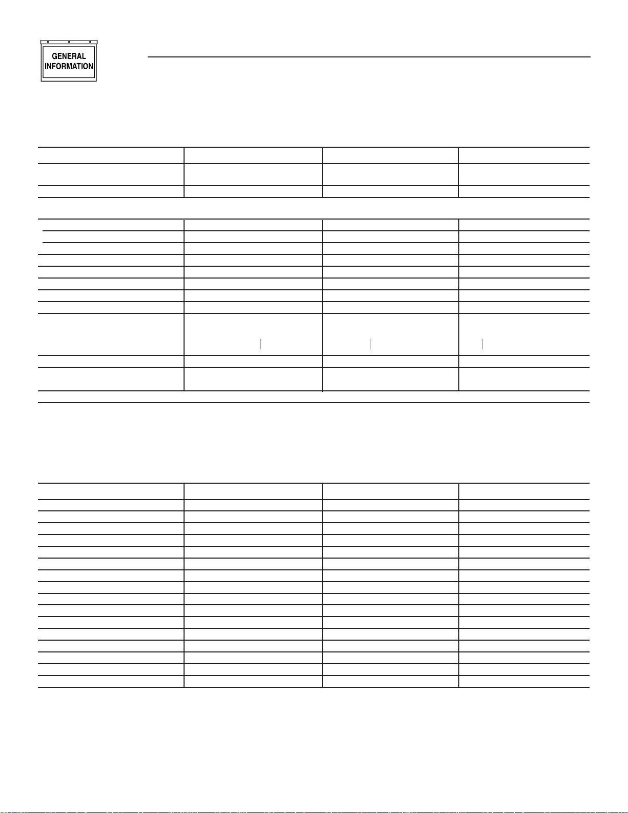
1.5 SPECIFICATIONS
1.5.1 GENERATOR
Model 04389 Model 04456 Model 04390
Rated Max. Continuous Power 6,000 NG/7,000 LP 12,000 NG/12,000 LP 13,000 NG/15,000 LP
Capacity (Watts*)
Rated Voltage 120/240 120/240 120/240
Rated Max. Continuous Load
Current (Amps)
120 Volts** 50.0 NG/58.3 LP 100.0 NG/100.0 LP 108.3 NG/125.0 LP
240 Volts 25.0 NG/29.2 LP 50.0 NG/50.0 LP 54.2 NG/62.5 LP
Main Line Circuit Breaker 30 Amp 50 Amp 65 Amp
Phase 1 1 1
Number of Rotor Poles 2 2 2
Rated AC Frequency 60 Hz 60 Hz 60 Hz
Power Factor 1 1 1
Recommended Air Filter Part # 0C8127 Part # 0C8127 Part # 0C8127
Battery Requirement Group 26/26R Group 26/26R Group 26/26R
12 Volts and 12 Volts and 12 Volts and
350 Cold-cranking 525 Cold-cranking 525 Cold-cranking
Amperes Minimum Amperes Minimum Amperes Minimum
Weight 375 Pounds 470 Pounds 487 Pounds
Output Sound Level @ 68 db (A) 70.5 db (A) 71.5 db (A)
23 ft (7m) at full load
Normal Operating Range -20°F (-28.8°C) to 104°F (40°C)
* Maximum wattage and current are subject to and limited by such factors as fuel Btu content, ambient temperature, altitude, engine power and condition, etc. Maximum power
decreases about 3.5 percent for each 1,000 feet above sea level; and also will decrease about 1 percent for each 6° C (10° F) above 16° C (60° F) ambient temperature.
** Load current values shown for 120 volts are maximum TOTAL values for two separate circuits. The maximum current in each circuit must not exceed the value stated for 240
volts.
1.5.2 ENGINE
Model 04389 Model 04456 Model 04390
Type of Engine GH-410 GT-760 GT-990
Number of Cylinders 1 2 2
Rated Horsepower 14.5 @ 3,600 rpm 26 @ 3,600 rpm 30 @ 3,600 rpm
Displacement 410cc 763cc 992cc
Cylinder Block Aluminum w/Cast Aluminum w/Cast Aluminum w/Cast
Iron Sleeve Iron Sleeve Iron Sleeve
Valve Arrangement Overhead Valves Overhead Valves Overhead Valves
Ignition System Solid-state w/Magneto Solid-state w/Magneto Solid-state w/Magneto
Recommended Spark Plug RC14YC RC12YC RC12YC
Spark Plug Gap 0.76 mm (0.030 inch) 0.508 mm (0.020 inch) 0.508 mm (0.020 inch)
Compression Ratio 8.6:1 9.5:1 9.5:1
Starter 12 Vdc 12 Vdc 12Vdc
Oil Capacity Including Filter Approx. 1.5 Qts Approx. 1.7 Qts Approx. 1.7 Qts
Recommended Oil Filter Part # 070185B Part # 070185B Part # 070185B
Recommended Air Filter Part # 0C8127 Part # 0C8127 Part # 0C8127
Operating RPM 3,600 3,600 3,600
6
M
M
OSE
G
G
T
OU
T
T
OSE
JUS
T
SCREW
UG
S
S
UG
Section 1 — General Information
Air-cooled 7 kW, 12 kW and 15 kW Generators
1.6 SYSTEM SET LED
The “System Set” LED is lit when all of the following
conditions are true:
1. The AUTO/OFF/MANUAL switch is set to the
AUTO position.
2. The utility voltage being supplied to the unit is
being sensed by the PCB. If the utility sense voltage is not connected to the unit or if it is below
168 volts AC, then the system set light will flash
rapidly. This indicates that if the AUTO/OFF/
MANUAL switch is placed in the Auto position,
the generator will start.
3. The “Not In Auto” dip switch is set to the OFF
position on the control board.
4. No alarms are present, for example, low oil pres-
sure, high temperature, etc.
1.7 FUEL REQUIREMENTS
AND RECOMMENDATIONS
With LP gas, use only the vapor withdrawal
system. This type of system uses the vapors formed
above the liquid fuel in the storage tank.
The engine has been fitted with a fuel carburetion
system that meets the specifications of the 1997
California Air Resources Board for tamper-proof
dual fuel systems. The unit will run on natural gas or
LP gas, but it has been factory set to run on natural
gas. Should the primary fuel need to be changed to
LP gas, the fuel system needs to be reconfigured. See
Section 1.9 for instructions on reconfiguration of the
fuel system.
Recommended fuels should have a Btu content of at
least 1,000 Btus per cubic foot for natural gas; or at
least 2,520 Btus per cubic foot for LP gas. Ask the
fuel supplier for the Btu content of the fuel.
Required fuel pressure for natural gas is 5 inches to
7 inches water colum (0.18 to 0.25 psi); and for
liquid propane, 10 inches to 12 inches of water
column (0.36 to 0.43 psi).
NOTE:
Any piping used to connect the generator to the
fuel supply should be of adequate size to ensure
the fuel pressure NEVER drops below 4 inches
water colum for natural gas or 10 inches water
column for liquid propane for all load ranges.
1.8 FUEL CONSUMPTION
Model # Nat. Gas (*) LP Vapor (**)
1/2 Load Full Load 1/2 Load Full Load
04389 66 119 0.82/30 1.47/54
04456 152 215 1.53/56 2.08/76
04390 156 220 1.58/58 2.40/88
*Natural gas is in cubic feet per hour.
**LP is in gallons per hour/cubic feet per hour.
*** Values given are approximate.
DANGER
Gaseous fuels such as natural gas and liquid
propane (LP) gas are highly explosive. Even the
slightest spark can ignite such fuels and cause
an explosion. No leakage of fuel is permitted.
Natural gas, which is lighter than air, tends to
collect in high areas. LP gas is heavier than air
and tends to settle in low areas.
1.9 RECONFIGURING THE
FUEL SYSTEM
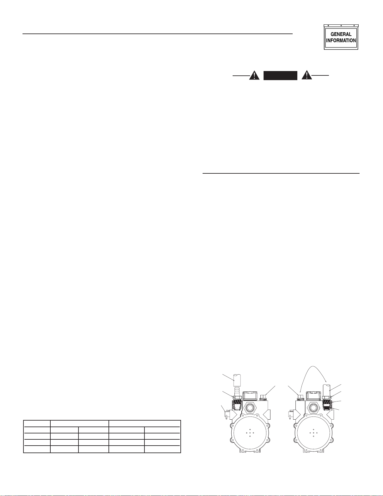
1.9.1 7 KW, 410CC ENGINE
To reconfigure the fuel system from NG to LP,
follow these steps (Figure 1.3):
NOTE:
The primary regulator for the propane supply is
NOT INCLUDED with the generator. A fuel pressure of 10 to 12 inches of water column (0.36 to
0.43 psi) to the fuel inlet of the generator MUST
BE SUPPLIED.
1. Turn off the main gas supply (if connected).
2. Open the roof and remove the door.
3. Remove the battery (if installed).
4. Disconnect wire #0 and wire #14 from the gas
solenoid on top of the demand regulator.
5. Remove the carburetor fuel hose from the outlet
port of the demand regulator.
6. Remove the demand regulator by removing the
fastener that retains the regulator mounting
bracket.
7. Remove the square headed steel pipe plug from
outlet port #1 and the brass hose barb fitting
from outlet port #2.
Figure 1.3 – Demand Regulator
HOSE & PL
WITCHED SIDE
FUEL H
BRASS HOSE
AD
TMEN
FITTIN
PL
NG FUEL SYSTE
7
LP FUEL SYSTE
FUEL H
BRASS HOSE
FITTIN
TLE
POR
FUEL JE
G
T
T
U
T
G
OSE
S
L
T
OR
OUSING PORT
JUSTER
SC
S
OU
S
Section 1 — General Information
Air-cooled 7 kW, 12 kW and 15 kW Generators
8. Refit the brass hose barb fitting to outlet port #1
and the square headed steel pipe plug to outlet
port #2.
9. Reverse procedure steps 1-5 to reinstall demand
regulator.
10. Take the plastic plug supplied in the poly-bag
with the generator and press it into the 3/4” hole
on the bottom of the air cleaner base (Figure
4.6).
11. Reverse the procedure to convert back to natural
gas.
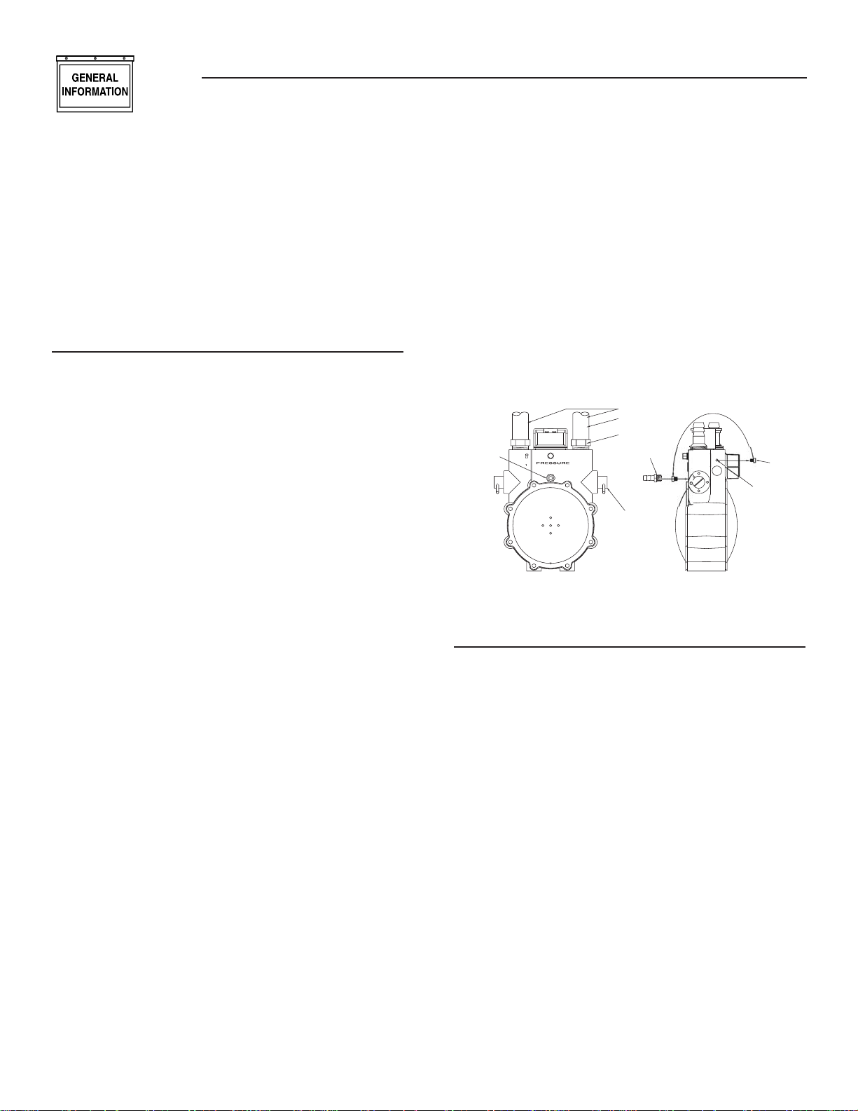
1.9.2 12KW AND 15KW, V-TWIN ENGINES
To reconfigure the fuel system from NG to LP, follow
these steps:
NOTE:
The primary regulator for the propane supply is
NOT INCLUDED with the generator. A fuel pressure of 10 to 12 inches of water column (0.36 to
0.43 psi) to the fuel inlet of the generator MUST
BE SUPPLIED.
1. Turn off the gas supply. (if connected)
2. Open the roof and remove the door.
3. Remove the battery. (if installed)
4. Remove the engine air in baffle located on the lefthand side of the battery compartment. Two M6
screws are located on top of the baffle and two
M6 screws are located on the inside of the baffle
towards the back.
5. Remove the small hose clamp and hose from the
fuel regulator. It may be necessary to pry the hose
off of the brass fitting using a screwdriver to gently lift up the hose edge.
6. Remove the small brass hose fitting from the
regulator casting.
7. Place the small fuel jet, thread side first, into the
threaded hole originally occupied by the brass
hose fitting (Figure 1.4).
8. Using a short No. 2 Phillips screw driver, thread
the small fuel jet into the regulator casting. Do
not over tighten.
9. Apply thread sealant to the threads of the hose
fitting and replace it into the regulator body.
10. Re-attach the small hose and hose clamp and
tighten as necessary.
11. Replace the engine air in baffle using the four M6
screws.
12. Identify both brass adjustment screws on the
regulator.
NOTE:
One adjustment screw can be accessed from the
front of the unit and the second can be accessed
from the back of the unit enclosure by removing
the plastic hole plug. The screw can be turned
with a long flat blade screwdriver.
8
13. To adjust the system to run on LP fuel, turn
BOTH adjuster screws 1/2 TURN CLOCKWISE.
The system should now be set for maximum
power and best perfomance. DO NOT, UNDER
ANY CIRCUMSTANCES, REMOVE THE SET
PINS FROM THE REGULATOR HOUSING.
THIS WILL VOID THE WARRANTY.
14. It may be necessary to make minor adjustments
to the preset adjustment screw settings to achieve
maximum power, particularly at higher altitudes.
If experiencing problems with the unit producing
maximum power, follow the procedure in Section
2.6 (Adjusting the Fuel Regulator).
Figure 1.4 - Demand Regulator
TLET PORT
FUEL H
BRASS HOSE
FITTIN
IDLE CIRCUI
POR
1/8 NP
BRASS HOSE
FITTIN
AD
REW
REGULAT
H
MAL
FUEL JE
1.10 LOCATION
1.10.1 GENERATOR
Install the generator set, in its protective enclosure,
outdoors, where adequate cooling and ventilating air
is always available. Consider these factors:
• Install the unit where air inlet and outlet open-
ings will not become obstructed by leaves, grass,
snow, etc. If prevailing winds will cause blowing or
drifting, consider using a windbreak to protect the
unit.
• Install the generator on high ground where water
levels will not rise and endanger it.
• Allow sufficient room on all sides of the generator
for maintenance and servicing. A good rule is to
allow three feet of space on all sides.
• Where strong prevailing winds blow from one
direction, face the generator air inlet openings to
the prevailing winds.
• Install the generator as close as possible to the fuel
supply, to reduce the length of piping.
• Install the generator as close as possible to
the transfer switch. HOWEVER, REMEMBER
THAT LAWS OR CODES MAY REGULATE THE
DISTANCE.
The genset must be installed on a level surface. The
base frame must be level within two (2) inches all
around.

Section 1 — General Information
Air-cooled 7 kW, 12 kW and 15 kW Generators
1.10.2 TRANSFER SWITCH
1.10.2.1 7 kW, 12 kW and 15 kW Units
The transfer switch shipped with this generator is
enclosed in a NEMA 1 enclosure. This type of enclo-
sure is intended for indoor use only. Follow these
rules:
• Install the transfer switch indoors on a firm, sturdy
supporting structure.
• To prevent switch distortion, level the switch if
necessary. This can be done by placing washers
between the switch enclosure and mounting surface.
• Never install the switch where water or any corrosive substance might drip onto the enclosure.
• Protect the switch at all times against excessive
moisture, dust, dirt, lint, construction grit and corrosive vapors.
If the AUTO/OFF/MANUAL switch is not set to its
OFF position, the generator can crank and start
as soon as the battery cables are connected. If
the utility power supply is not turned off, sparking can occur at the battery posts and cause an
explosion.
1.11 BATTERY INSTALLATION
Fill the battery with the proper electrolyte fluid if
necessary and have the battery fully charged before
installing it.
Before installing and connecting the battery, complete
the following steps:
1. Set the generator's AUTO/OFF/MANUAL switch to
OFF.
2. Turn off utility power supply to the transfer
switch.
3. Remove the 7.5A and 15A fuses from the genera-
tor control panel.
Battery cables were factory connected at the generator (Figure 1.5). Connect cables to battery posts as
follows:
Figure 1.5 – Battery Cable Connections
4. Connect the red battery cable (from starter contactor) to the battery post indicated by a positive,
POS or (+).
5. Connect the black battery cable (from frame
ground) to the battery post indicated by a negative, NEG or (—).
NOTE:
Damage will result if battery connections are made
in reverse.
NOTE:
The generator is equipped with a battery trickle
charger that is active when the unit is set up for
automatic operation. With the battery installed
and utility power source voltage available to the
transfer switch, the battery receives a trickle
charge while the engine is not running, to prevent
self-discharge. The trickle charger is designed to
help extend the life of the battery by maintaining the battery when the unit is not running. The
trickle charge feature cannot be used to recharge
a discharged battery.
1.12 THE BATTERY
DANGER
Do not dispose of the battery in a fire. The
battery is capable of exploding.
A battery presents a risk of electrical shock
and high short circuit current. The following precautions are to be observed when working on
batteries:
• Remove the 7.5A and 15A fuses from the genera-
tor control panel.
• Remove watches, rings or other metal objects;
• Use tools with insulated handles;
• Wear rubber gloves and boots;
• Do not lay tools or metal parts on top of the
battery; and
• Disconnect charging source prior to connecting or
disconnecting battery terminals.
Do not open or mutilate the battery. Released
electrolyte has been known to be harmful to the
skin and eyes, and to be toxic.
The electrolyte is a dilute sulfuric acid that is
harmful to the skin and eyes. It is electrically
conductive and corrosive.
The following procedures are to be observed:
• Wear full eye protection and protective clothing;
• Where electrolyte contacts the skin, wash it off
immediately with water;
• Where electrolyte contacts the eyes, flush
thoroughly and immediately with water and seek
medical attention; and
9
Section 2 — Post Installation Start-up and Adjustments
Air-cooled 7 kW, 12 kW and 15 kW Generators
• Spilled electrolyte is to be washed down with an
acid neutralizing agent. A common practice is to
use a solution of 1 pound (500 grams) bicarbonate
of soda to 1 gallon (4 liters) of water. The bicarbonate of soda solution is to be added until the
evidence of reaction (foaming) has ceased. The
resulting liquid is to be flushed with water and the
area dried.
Lead-acid batteries present a risk of fire because
they generate hydrogen gas. The
following procedures are to be followed:
• DO NOT SMOKE when near the battery;
• DO NOT cause flame or spark in battery area; and
• Discharge static electricity from body before touching the battery by first touching a grounded metal
surface.
Be sure the AUTO/OFF/MANUAL switch is set to
the OFF position before connecting the battery
cables. If the switch is set to AUTO or MANUAL,
the generator can crank and start as soon as the
battery cables are connected.
Be sure the utility power supply is turned off
and the 7.5A and 15A fuses are removed from
the generator control panel, or sparking may
occur at the battery posts as the cables are
attached and cause an explosion.
Servicing of the battery is to be performed or supervised by personnel knowledgeable of batteries and
the required precautions. Keep unauthorized personnel away from batteries.
When replacing the battery, use the following type of
battery: Group 26/26R 12-volt DC, negative ground
battery with a rating of 350 cold-cranking amps minimum for 7 kW; 525 cold-cranking amps minimum
for 12 and 15 kW at -17.8º C (0º F) minimum. When
using a maintenance-free battery, it is not necessary
to check the specific gravity or electrolyte level. Have
these procedures performed at the intervals specified
in the “Service Schedule.” A negative ground system
is used. Battery connections are shown on the wiring
diagrams. Make sure the battery is correctly connected and terminals are tight. Observe battery polarity
when connecting the battery to the generator set.
2.1 BEFORE INITIAL START-UP
Before starting, complete the following:
1. Set the generator’s main circuit breaker to its
OFF (or open) position.
2. Set the generator's AUTO/OFF/MANUAL switch to
the OFF position.
3. Turn OFF the utility power supply to the transfer
switch using the means provided (such as the
utility main line circuit breaker).
4. Turn OFF all loads connected to the transfer
switch terminals T1 and T2.
10
5. Check the engine crankcase oil level and, if necessary, fill to the dipstick FULL mark with the recommended oil. Do not fill above the FULL mark.
6. Check the fuel supply. Gaseous fuel lines must
have been properly purged and leak tested in
accordance with applicable fuel-gas codes. All
fuel shutoff valves in the fuel supply lines must
be open.
Never operate the engine with the oil level
below the “Add” mark on the dipstick. Doing
this could damage the engine.
2.2 CHECK TRANSFER SWITCH
OPERATION
Refer to Section 3.5, of the owner’s manual for manual operation procedures.
DANGER
Do not attempt manual transfer switch opera-
tion until all power voltage supplies to the
transfer switch have been positively turned off.
Failure to turn off all power voltage supplies
will result in extremely hazardous and possibly
fatal electrical shock.
2.3 ELECTRICAL CHECKS
Complete electrical checks as follows:
1. Set the generator's main circuit breaker to its
OFF (or open) position.
2. Set the generator's Auto/Off/Manual switch to the
OFF position.
3. Turn OFF all loads connected to the transfer
switch terminals T1 and T2.
4. Turn on the utility power supply to the transfer
switch using the means provided (such as a utility
main line circuit breaker).
DANGER
The transfer switch is now electrically “hot.”
Contact with “hot” parts will result in extremely
hazardous and possibly fatal electrical shock.
Proceed with caution.
5. Use an accurate AC voltmeter to check utility
power source voltage across transfer switch terminals N1 and N2. Nominal line-to-line voltage
should be 240 volts AC.
6. Check utility power source voltage across terminals N1 and the transfer switch neutral lug; then
across terminal N2 and neutral. Nominal line-toneutral voltage should be 120 volts AC.
Section 2 — Post Installation Start-up and Adjustments
Air-cooled 7 kW, 12 kW and 15 kW Generators
7. When certain that utility supply voltage is compatible with transfer switch and load circuit ratings,
turn OFF the utility power supply to the transfer
switch.
8. On the generator panel, set the AUTO/OFF/
MANUAL switch to MANUAL. The engine should
crank and start.
9. Let the engine warm up for about five minutes to
allow internal temperatures to stabilize. Then, set
the generator’s main circuit breaker to its ON (or
CLOSED) position.
DANGER
Proceed with caution! Generator power voltage
is now supplied to the transfer switch. Contact
with live transfer switch parts will result in dangerous and possibly fatal electrical shock.
10. Connect an accurate AC voltmeter and a frequency meter across transfer switch terminal
lugs E1 and E2. Voltage should be 242-252 volts;
frequency should read about 61-63 Hertz.
11. Connect the AC voltmeter test leads across terminal lug E1 and neutral; then across E2 and
neutral. In both cases, voltage reading should be
121-126 volts AC.
12. Set the generator’s main circuit breaker to its
OFF (or open) position. Let the engine run at noload for a few minutes to stabilize internal engine
generator temperatures.
13. Set the generator's AUTO/OFF/MANUAL switch to
OFF. The engine should shut down.
NOTE:
It is important not to proceed until certain that
generator AC voltage and frequency are correct
and within the stated limits. Generally, if both AC
frequency and voltage are high or low, the engine
governor requires adjustment. If frequency is correct, but voltage is high or low, the generator’s
voltage regulator requires adjustment.
Do not attempt manual transfer switch opera-
tion until all power voltage supplies to the
transfer switch have been positively turned off.
Failure to turn off all power voltage supplies
will result in extremely hazardous and possibly
fatal electrical shock.
5. Manually set the transfer switch to the STANDBY
position, i.e., load terminals connected to the
generator's E1/E2 terminals. The transfer switch
operating lever should be down.
6. Set the generator's AUTO/OFF/MANUAL switch
to MANUAL. The engine should crank and start
immediately.
7. Let the engine stabilize and warm up for a few
minutes.
8. Set the generator’s main circuit breaker to its ON
(or closed) position. Loads are now powered by
the standby generator.
9. Turn ON electrical loads connected to transfer
switch T1 and T2. Apply an electrical load equal
to the full rated wattage/amperage capacity of the
installed generator.
10. Connect an accurate AC voltmeter and a frequency meter across terminal lugs E1 and E2. Voltage
should be greater than 230 volts; frequency
should be greater than 58 Hertz.
11. Let the generator run at full rated load for 20-30
minutes. Listen for unusual noises, vibration or
other indications of abnormal operation. Check
for oil leaks, evidence of overheating, etc.
12. When testing under load is complete, turn OFF
electrical loads.
13. Set the generator's main circuit breaker to its
OFF (or OPEN) position.
14. Let the engine run at no-load for a few minutes.
15. Set the AUTO/OFF/MANUAL switch to OFF. The
engine should shut down.
2.4 GENERATOR TESTS UNDER LOAD
To test the generator set with electrical loads applied,
proceed as follows:
1. Set generator’s main circuit breaker to its OFF
(or OPEN) position.
2. Turn OFF all loads connected to the transfer
switch terminals T1 and T2.
3. Set the generator's AUTO/OFF/MANUAL switch to
OFF.
4. Turn OFF the utility power supply to the transfer
switch, using the means provided (such as a utility main line circuit breaker).
2.5 CHECKING AUTOMATIC
OPERATION
To check the system for proper automatic operation,
proceed as follows:
1. Set generator’s main circuit breaker to its OFF
(or OPEN) position.
2. Check that the AUTO/OFF/MANUAL switch is set
to OFF.
3. Turn OFF the utility power supply to the transfer
switch, using means provided (such as a utility
main line circuit breaker).
4. Manually set the transfer switch to the UTILITY
position, i.e., load terminals connected to the utility power source side.
11
Section 2 — Post Installation Start-up and Adjustments
Air-cooled 7 kW, 12 kW and 15 kW Generators
5. Turn ON the utility power supply to the transfer
switch, using the means provided (such as a utility main line circuit breaker).
6. Set the AUTO/OFF/MANUAL switch to AUTO. The
system is now ready for automatic operation.
7. Turn OFF the utility power supply to the transfer
switch.
With the AUTO/OFF/MANUAL switch at AUTO, the
engine should crank and start when the utility source
power is turned OFF. After starting, the transfer
switch should connect load circuits to the standby
side. Let the system go through its entire automatic
sequence of operation.
With the generator running and loads powered by
generator AC output, turn ON the utility power supply
to the transfer switch. The following should occur:
• After about 13 seconds, the switch should transfer
loads back to the utility power source.
• About one minute after retransfer, the engine
should shut down.
2.6 ADJUSTING THE REGULATOR
(NATURAL GAS ONLY)
Although the generator has been factory set to provide maximum power, it may be necessary in some
areas to adjust this setting. Because natural gas has
different BTU or power content across the country
the engine may not perform as designed.
If experiencing engine problems at high or full load
conditions follow these steps. It will require a frequency meter to perform this procedure.
1. Turn off utility power to the main distribution
panel in the house. This can be done by switching
the service main breaker to the off or open position.
2. Allow the generator to start. Before loading the
generator, confirm that the No Load Frequency,
with the roof open and door off, is set to 63-63.5
Hz. Transfer load to emergency circuits.
3. Turn on appliances, lights, pumps, etc., that are
on the emergency circuits in an attempt to fully
load the generator. Be cautious not to overload
the generator. Use the following chart as a guide:
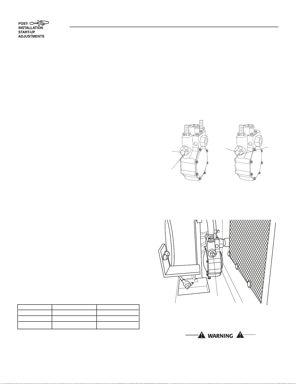
5. The fuel regulator is fitted with one (7 kW), or two
(12 & 15 kW) adjustment screws. While watching the frequency meter, slowly turn the adjustment screws clockwise or counterclockwise one
at a time until the highest frequency is read on
the meter. Only limited adjustment is available
because of the set pin. Under no circumstances
should any of the pins be removed (Figures 2.1
and 2.2).
Figure 2.1 — Dual Fuel Regulators
V-twin
Adjustment
Screw
(Both Sides)
Set Pin
(Both Sides)
Adjustment
Screw
(One Side
Only)
6. When the highest frequency is reached maximum
power has been set. From this point turn both
adjustment screws 1/4 turn counterclockwise.
The regulator is now set.
410
Set
Pin
Figure 2.2 — Placement of Regulator
Adjustment Screw
Unit 120 Volts 240 Volts
7 kW 50.0 amps 25.0 amps
12 kW 100.0 amps 50.0 amps
13 kW 108.3 amps 54.1 amps
4. When 3/4 load has been achieved. Connect a frequency meter to the output lugs of the generator’s
main line circuit breaker.
12
7. Turn utility power to the main distribution panel
back on. This can be done by switching the service main breaker to the on or closed position.
Allow the generator to shut down.
Do not make any unnecessary adjustments.
Factory settings are correct for most applications. However, when making adjustments, be
careful to avoid overspeeding the engine.
Section 2 — Post Installation Start-up and Adjustments
Air-cooled 7 kW, 12 kW and 15 kW Generators
If this procedure or the equipment are not available,
locate the nearest Dealer and they can perform the
adjustments.
NOTE:
A service fee may be charged for this adjustment.
2.7 ENGINE GOVERNOR ADJUSTMENT
If both AC frequency and voltage are correspondingly
high or low, adjust the engine governor as follows:
2.7.1 7 KW UNITS
1. Loosen the governor clamp bolt (Figures 2.3).
2. Hold the governor lever at its wide open throttle
position, and rotate the governor shaft clockwise
as far as it will go. Then, tighten the governor
lever clamp bolt to 70 inch-pounds (8 N-m).
3. Start the generator; let it stabilize and warm up
at no-load.
4. Connect a frequency meter across the generators
AC output leads.
5. Turn the primary adjust screw to obtain a frequency reading of 61.5 Hertz. Turn the secondary
adjust screw to obtain a frequency of 62.5 Hz.
6. When frequency is correct at no load, check the
AC voltage reading. If voltage is incorrect, the voltage regulator may require adjustment.
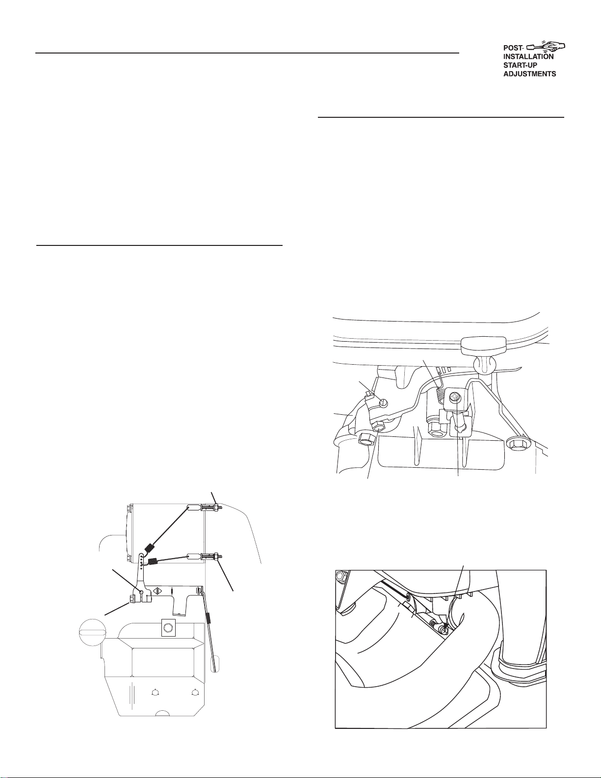
2.7.2 12 KW AND 15 KW UNITS
1. Loosen governor clamp bolt (See Figure 2.4).
2. Completely remove the idle spring.
3. With governor arm at wide open throttle position,
rotate governor shaft fully clockwise. Tighten
clamp bolt to 84 inch-pounds.
4. Start unit and apply full load. Use full load speed
adjust screw (Figure 2.5) to adjust frequency to
58 Hz.
5. Remove load, stop engine, loosen the idle adjust
screw and reconnect the idle spring.
6. Using a hand, push the governor arm to the
closed throttle position. Make sure the idle spring
does not stretch at all.
Figure 2.4 — Engine Governor Adjustment
V-twin Engines
Idle Spring
Governor
Shaft
(Rotate
Clockwise)
Figure 2.3 — Engine Governor Adjustment
Single Cylinder Engines
SECONDARY
ADJUST SCREW
GOVERNOR
SHAFT
GOVERNOR
CLAMP
BOLT
PRIMARY
ADJUST
SCREW
Governor Clamp Bolt
No Load Idle
Adjustment Screw
Figure 2.5 — Full Load Speed Adjust Screw
V-twin Engines
Full Load Speed Adjust Screw
13
Section 3 — Operation
Air-cooled 7 kW, 12 kW and 15 kW Generators
7. Restart the unit.
8. Slowly turn the idle adjust screw to adjust the
no-load idle frequency to 63-63.5 Hz (with door
open).
9. The governor is now set.
2.7.3 ADDITIONAL CORROSION
PROTECTION
Periodically spray all engine linkage parts and brackets with corrosion inhibiting spray such as WD-40 or
a comparable product.
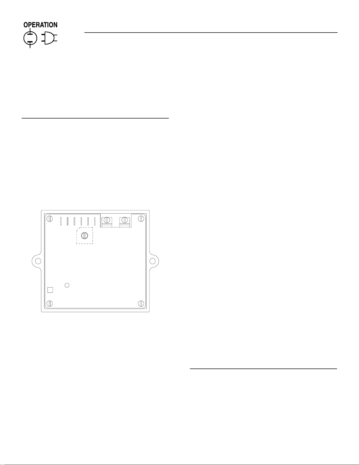
2.8 VOLTAGE REGULATOR
ADJUSTMENT
With the frequency between 62-63 Hertz, slowly turn
the slotted potentiometer (Figure 2.6) until line voltage reads 247-252 volts.
Figure 2.6 – Voltage Adjustment Potentiometer
NOTE:
The access panel on top of the control panel must
be removed to adjust the voltage regulator.
NOTE:
The voltage regulator is housed above the generator's control panel. The regulator maintains a
voltage in direct proportion to frequency at a 2-to1 ratio. For example, at 62 Hertz, line-to-neutral
voltage will be 124 volts.
3.1 BREAK-IN PROCEDURE
Once the unit has been installed and all electrical
checks have been made, it is strongly recommended
that the following “Break-in Procedure” be completed
to ensure correct generator operation in the future.
1. Set the generator’s AUTO/OFF/MANUAL switch to
AUTO.
2. Turn OFF the utility power supply to the transfer
switch using the means provided (such as a utility
main line circuit breaker).
3. The unit will start, and the transfer switch will
transfer to standby.
4. Using the transfer switch’s built-in emergency
load center, turn on circuits to load the generator
to approximately 25% rated load and run the unit
for one hour.
5. Run the unit for one hour at 50% rated load.
6. Run the unit for one hour at 75% rated load.
7. Run the unit for one hour at 100% rated load.
8. Turn ON the utility power supply to the transfer
switch, which will allow the transfer switch to
transfer back to utility power. The unit will continue to run for one minute and then shut down.
9. Allow the unit to cool.
10. Set the generator’s main circuit breaker to its
OFF (or OPEN) position.
11. Set the generator's AUTO/OFF/MANUAL switch
to OFF. Remove the 7.5A and 15A fuses from the
generator control panel. Disconnect the battery
cables as outlined in “General Hazards”.
12. Drain the oil and remove the oil filter. Replace
the oil filter according to Section 4.4, “Changing
the Oil Filter”. Replace the oil with synthetic oil
as recommended in Section 4.3, “Changing the
Engine Oil”.
13. Reconnect the battery cables as outlined in
“General Hazards” (page 2) and insert the 7.5A
and 15A fuses into the generator control panel.
The generator is now ready for service.
3.2 USING THE AUTO/OFF/MANUAL
SWITCH (FIGURE 3.1)
3.2.1 “AUTO” POSITION
Selecting this switch position activates fully automatic system operation. It also allows personnel to
start and exercise the engine every seven days with
the setting of the exercise timer (see Section 3.6).
This position also is used for remote starting, when
it is set up.
14
C
SSO
OU
X
SE
SYST
SET
O
5A
OU
USE
OFF
S
S
S
OSS
O
S
O
K
L
O
D
.
SYS
T
CIRCUIT
GFCI
Air-cooled 7 kW, 12 kW and 15 kW Generators
3.2.2 “OFF” POSITION
This switch position shuts down the engine. This
position also prevents automatic operation.
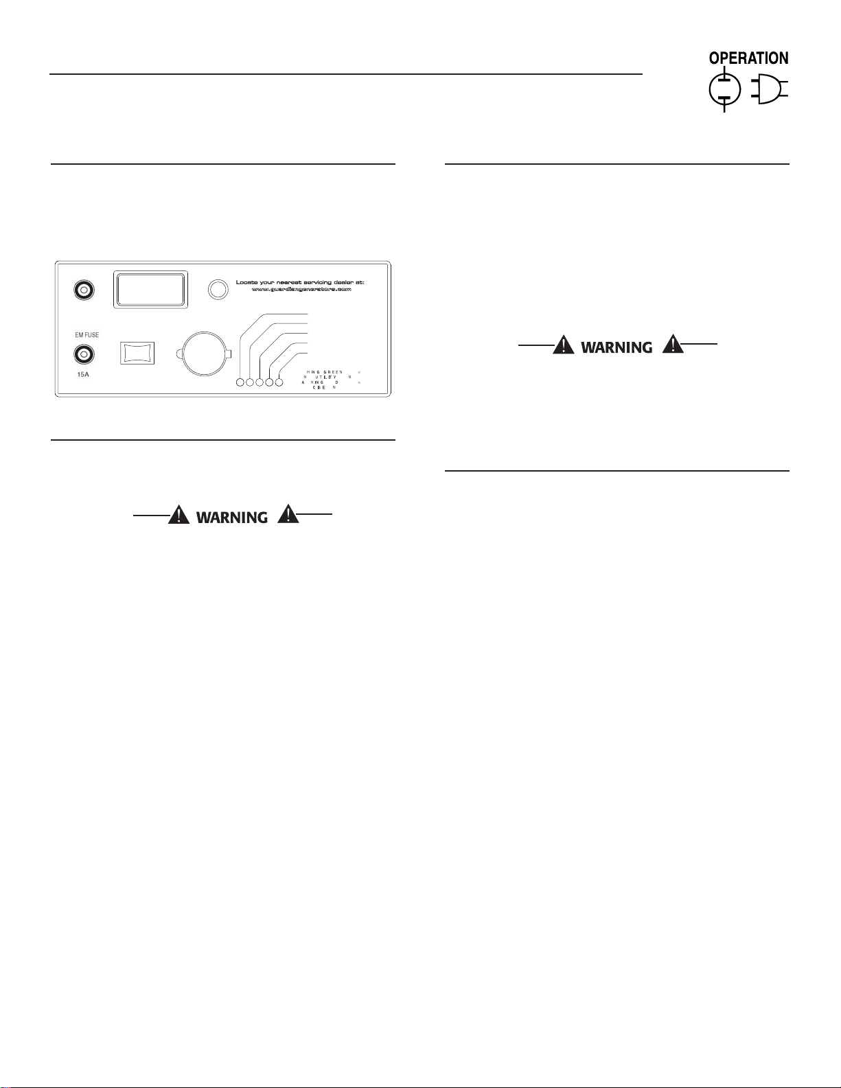
Figure 3.1 – Generator Control Panel
TLET F
7.
AUT
EXERCI
3.2.3 “MANUAL” POSITION
12 VD
ACCE
TLET 7.5A MA
RY
Set the switch to MANUAL to crank and start the
engine. Transfer to standby power will not occur
unless there is a utility failure.
With the switch set to AUTO, the engine may
crank and start at any time without warning.
Such automatic starting normally occurs when
utility power source voltage drops below a preset level or during the normal exercise cycle. To
prevent possible injury that might be caused
by such sudden starts, always set the switch to
OFF and remove the fuses before working on or
around the generator or transfer switch. Then,
place a “DO NOT OPERATE” tag on the generator panel and on the transfer switch.
TEM SE
LOW OI
HIGH TEMP
VER SPEE
VER CRAN
Section 3 — Operation
3.3.1 12 VDC ACCESSORY OUTLET
Your generator is equipped with a 12 VDC accessory
outlet in the Generator Control Panel. (Figure 3.1)
With the generator running or in standby mode, this
outlet may be used to temporarily power low power
accessories such as a work light, cell phone, radio or
any other automotive style accessory. This outlet is
capable of delivering a MAXIMUM of 7.5 Amps. If the
accessory to be used through this circuit demands
too much power, the fuse that protects this circuit
will melt open and the circuit will not be functional.
This 12 VDC outlet draws power from the gen-
erator's starting battery and extended use of
this outlet may drain the battery and the
engine may not start. This outlet should NOT be
used for battery charging.
3.3.2 120 VAC GFCI OUTLET
Your generator is equipped with an external, 15 amp,
120 volt, GFCI convenience outlet that is located in
the right rear of the generator enclosure. (Figures
1.1 and 1.2) When the generator is running, in the
absence of utility power, this outlet may be used
to power items outside your home such as lights
or power tools. This outlet may also be used when
utility power is present by running the generator in
manual mode. This oultlet does not provide power if
the generator is not running. This outlet is protected
by a 15-amp circuit breaker located in the generator
control panel. (Figure 3.1).
3.4 SEQUENCE OF AUTOMATIC
3.3 AUTOMATIC TRANSFER
OPERATION
To select automatic operation, do the following:
1. Make sure the transfer switch main contacts are
set to their UTILITY position, i.e., loads connected to the utility power source (Figure 3.2).
2. Be sure that normal UTILITY power source volt-
age is available to transfer switch terminal lugs
N1 and N2.
3. Set the generator’s AUTO/OFF/MANUAL switch to
AUTO.
4. Set the generator’s main circuit breaker to its ON
(or closed) position.
With the preceding steps complete, the generator will
start automatically when utility source voltage drops
below a preset level. After the unit starts, loads are
transferred to the standby power source. Refer to
Section 3.4, “Sequence of Automatic Operation.”
OPERATION
The generator’s control panel houses a control logic
circuit board. This board constantly monitors utility power source voltage. Should that voltage drop
below a preset level, circuit board action will signal
the engine to crank and start. After the engine starts,
the circuit board signals the transfer switch to activate and connect load circuits to the standby power
supply (load terminal lugs T1/T2 connect to terminal
lugs E1/E2).
Upon restoration of utility source voltage above a
preset level, generator circuit board action signals the
transfer switch to transfer loads back to that power
supply. After retransfer, the engine is signalled to shut
down.
The actual sequence of operation is controlled by
sensors and timers on a control logic circuit board,
as follows:
A. Utility Voltage Dropout Sensor
• This sensor monitors utility source voltage.
15
Section 3 — Operation
Air-cooled 7 kW, 12 kW and 15 kW Generators
• If utility source voltage drops below about 60
percent of the nominal supply voltage, the sensor
energizes a 15-second timer.
• Once the timer has expired, the engine will crank
and start.
B. Engine Warm-up Time Delay
• This mechanism lets the engine warm up for
about 10 seconds before the load is transferred
to the standby source.
C. Standby Voltage Sensor
• This sensor monitors generator AC output voltage. When the voltage has reached 50 percent of
the nominal rated voltage, transfer to standby
can occur.
D. Utility Voltage Pickup Sensor
• This sensor monitors utility power supply voltage. When that voltage is restored above 70 percent of the nominal source voltage, a retransfer
time delay starts timing.
E. Retransfer Time Delay
• This timer runs for about 15 seconds.
• At end of a 15-second delay, circuit board
action de-energizes transfer relay in the transfer
switch.
• Retransfer to utility power source then occurs.
F. Engine Cool-down Timer
• When the load is transferred back to utility power
source, the engine cool-down timer starts timing.
• The timer will run for about one minute, and the
generator will then shut down.
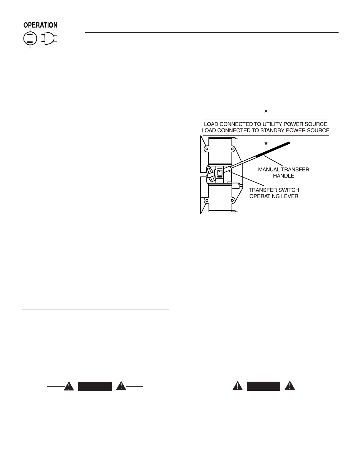
4. Use the manual transfer handle inside the transfer switch to move the main contacts to their
“Standby” position, i.e., loads connected to the
standby power source (Figure 3.2).
Figure 3.2 – Manual Transfer Switch Operation
5. To crank and start the engine, set the AUTO/OFF/
MANUAL switch to MANUAL.
6. Let the engine stabilize and warm up for a few
minutes.
7. Set the generator’s main circuit breaker to its ON
(or closed) position. The standby power source
now powers the loads.
3.5 MANUAL TRANSFER OPERATION
3.5.1 TRANSFER TO GENERATOR
POWER SOURCE
To start the generator and activate the transfer switch
manually, proceed as follows:
1. Set the generator’s AUTO/OFF/MANUAL switch to
OFF.
2. Set the generator’s main circuit breaker to its
OFF (or open) position.
3. Turn OFF the utility power supply to the transfer
switch using the means provided (such as a utility
main line circuit breaker).
DANGER
Do not attempt to activate the transfer switch
manually until all power voltage supplies to the
switch have been positively turned off. Failure
to turn off all power voltage supplies may result
in extremely hazardous and possibly fatal electrical shock.
16
3.5.2 TRANSFER BACK TO UTILITY POWER
SOURCE
When utility power has been restored, transfer back
to that source and shut down the generator. This can
be accomplished as follows:
1. Set the generator’s main circuit breaker to its
OFF (or open) position.
2. Let the engine run for a minute or two at no-load
to stabilize the internal temperatures.
3. Set the generator’s AUTO/OFF/MANUAL switch to
its OFF (or open) position. The engine should
shut down.
4. Check that utility power supply to the transfer
switch is turned OFF.
DANGER
Do not attempt to activate the transfer switch
manually until all power voltage supplies
to the switch have been positively turned off.
Failure to turn off all power voltage supplies
may result in extremely hazardous and possibly
fatal electrical shock.
Section 3 — Operation
Air-cooled 7 kW, 12 kW and 15 kW Generators
5. Use the manual transfer handle inside the transfer switch to move the main contacts back to their
UTILITY position, i.e., loads connected to the utility power source (Figure 3.2).
6. Turn ON the utility power supply to the transfer
switch using the means provided.
7. Set the system to automatic operation as outlined
in “Automatic Transfer Operation,” Section 3.3.
3.6 SETTING THE EXERCISE TIMER
This generator is equipped with an exercise timer.
Once it is set, the generator will start and exercise
once every seven days, on the day of the week and at
the time of day the following sequence is completed.
During this exercise period, the unit runs for approximately 12 minutes and then shuts down. Transfer of
loads to the generator output does not occur during
the exercise cycle.
A switch on the control panel (see Figure 3.1) permits selection of the day and time for the system to
exercise. At the chosen time, perform the following
sequence to select the desired day and time of day the
system will exercise.
1. Verify that the AUTO/OFF/MANUAL switch is set
to AUTO.
2. Hold down the “Set Exercise Time” switch until
the generator starts (approximately 10 seconds)
and then release.
3. The generator will start and run for approximately 12 minutes and then shut down on its own.
The exerciser will then be set to run at that time
of day every week.
NOTE:
The exerciser will only work in the AUTO mode
and will not work unless this procedure is performed. The exerciser will need to be reset every
time the 12-volt battery is disconnected and then
reconnected.
The exerciser WILL NOT work if dip switch 2 on
the controller printed circuit board (Remote Not
Auto) is ON.
3.7 PROTECTION SYSTEMS
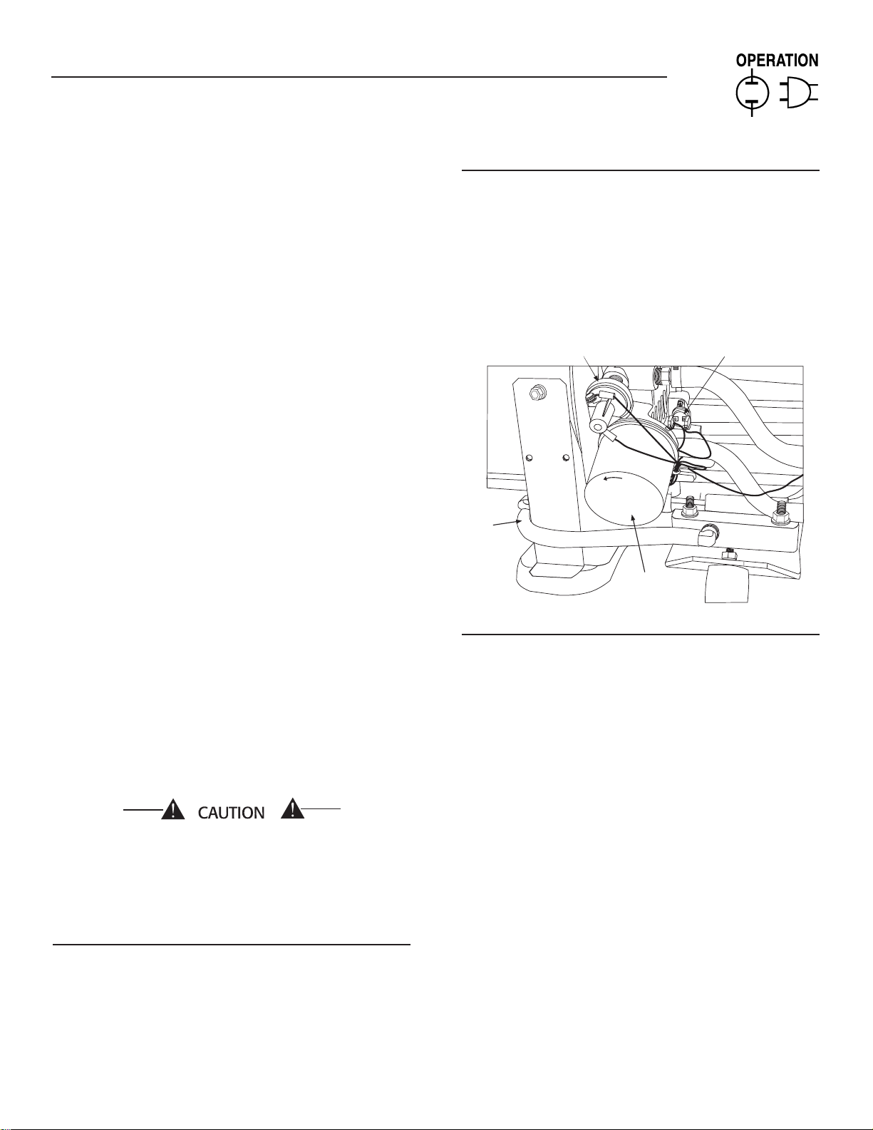
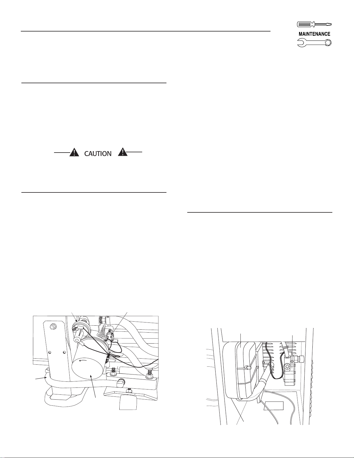
3.7.1 LOW OIL PRESSURE SWITCH
This switch (Figure 3.3) has normally closed contacts that are held open by engine oil pressure during cranking and operating. Should oil pressure
drop below the 8 psi range, switch contacts close,
and the engine shuts down. The unit should not be
restarted until oil is added. The AUTO/OFF/MANUAL
switch must then be turned to OFF and then back to
AUTO.
3.7.2 HIGH TEMPERATURE SWITCH
This switch’s contacts (Figure 3.3) close if the temperature should exceed approximately 140º C (284º
F), initiating an engine shutdown. The generator will
automatically restart and the LED on the generator
control panel will reset once the temperature has
returned to a safe operating level.
Figure 3.3 – Low Oil Pressure and
High Temperature Switches
Low Oil Switch
L
o
o
s
e
n
Oil
Drain
Hose
Oil Filter
3.7.3 OVERCRANK
This feature prevents the generator from damaging
itself when it continually attempts to start and another problem, such as no fuel supply, prevents it from
starting. The unit will crank and rest for a preset
time limit. Then, it will stop cranking, and the LED
on the generator control panel will light indicating an
overcrank failure. The AUTO/OFF/MANUAL switch
will need to be set to OFF and then back to AUTO to
reset the generator control board.
NOTE:
If the fault is not repaired, the overcrank feature
will continue to activate.
High Temp Switch
3.7.3.1 Approximate Crank Cycle Times
• 15 seconds ON
• 7 seconds OFF
• 7 seconds ON
• 7 seconds OFF
• Repeat for 45 seconds
Approximately 90 seconds total
17
CACCESSO
OU
X
SE
SYST
SET
O
5A
OU
USE
OFF
S
S
S
OSS
O
S
O
K
L
O
D
.
SYS
T
CIRCUIT
GFCI
Section 4 — Maintenance
Air-cooled 7 kW, 12 kW and 15 kW Generators
3.7.4 OVERSPEED
This feature protects the generator from damage by
shutting it down if it happens to run faster than the
preset limit. This protection also prevents the generator from supplying an output that could potentially damage appliances connected to the generator
circuit. Contact the nearest Authorized Dealer if this
failure occurs.
4.1 FUSES
The generator panel's 15-amp fuse (Figure 4.1) protects the DC control circuit and the battery charge
circuit against overload. This fuse is wired in series
with the battery output lead to the panel. If this fuse
element has melted open, the engine will not be able
to crank or start. The generator will also lose all battery charge capabilities. Replace this fuse using only
an identical 15-amp replacement fuse. To replace the
fuse, push the fuse holder cap down and rotate it
counterclockwise.
The generator panel's 7.5-amp fuse protects the
12 VDC accessory socket. If the fuse element has
melted open, the 12 VDC socket will not be able to
provide power to any accessories. Replace this fuse
using only an identical 7.5-amp replacement fuse. To
replace the fuse, push the fuse holder cap down and
rotate it counterclockwise.
3. Install the dipstick; then, remove it again. The oil
level should be at the dipstick “Full” mark. If necessary, add oil to the “Full” mark only. DO NOT
FILL ABOVE THE “FULL” MARK.
Never operate the engine with the oil level
below the “Add” mark on the dipstick. Doing
this could damage the engine.
4. Install the dipstick.
5. Reset the AUTO/OFF/MANUAL switch to its original position.
Figure 4.2 — Oil Dipstick and Fill, 7 kW
Oil Dipstick and Fill
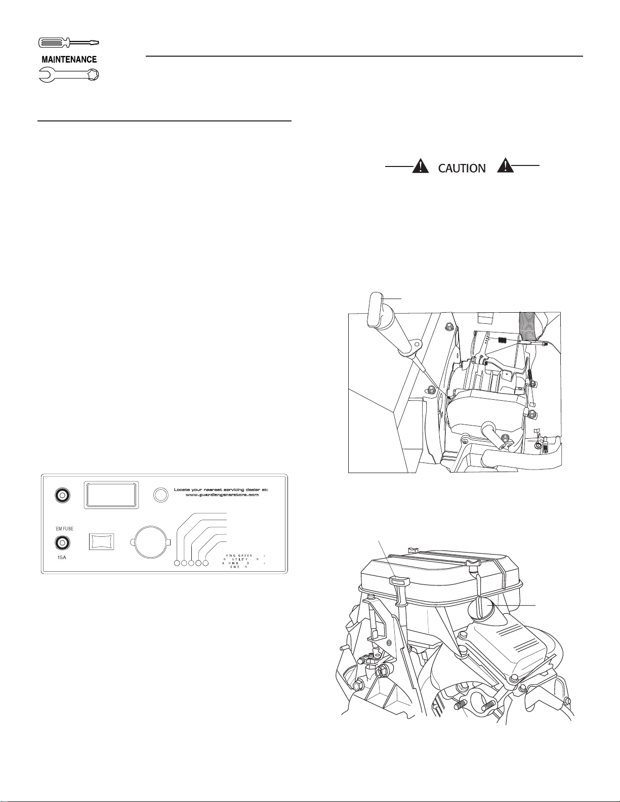
Figure 4.1 – Generator Control Panel
TLET F
7.
AUT
EXERCI
12 VD
TLET 7.5A MA
RY
TEM SE
LOW OI
HIGH TEMP
VER SPEE
VER CRAN
4.2 CHECKING THE ENGINE
OIL LEVEL
For oil capacities, see “Specifications,” Section 1.5.
For engine oil recommendations, see Section 4.3.1.
To check the engine oil level, proceed as follows
(Figures 4.2 and 4.3):
1. Start the generator by moving the AUTO/OFF/
MANUAL switch to the MANUAL position. Allow
it to run for a short while and then shut it down
by moving the switch to the OFF position.
2. Remove the dipstick and wipe it dry with a clean
cloth.
Figure 4.3 — Oil Dipstick and Fill,
12 kW and 15 kW
Oil Dipstick
Oil Fill
18
Section 4 — Maintenance
Air-cooled 7 kW, 12 kW and 15 kW Generators
4.3 CHANGING THE ENGINE OIL
4.3.1 ENGINE OIL RECOMMENDATIONS
Use oil of American Petroleum Institute (API) Service
Class SG, SH or SJ. Use all season SAE 5W-30
Synthetic oil. Organic break-in oil is required before
using synthetic oil.
NOTE:
The unit is supplied with “break-in” oil. See the
“Break-in Procedure,” Section 3.1, for the first
required oil change.
Any attempt to crank or start the engine before
it has been properly serviced with the recommended oil may result in an engine failure.
4.3.2 OIL CHANGE PROCEDURE
To change the oil, proceed as follows:
1. Run the engine until it is thoroughly warmed up
then shut OFF the engine.
2. Immediately after the engine shuts OFF, pull the
oil drain hose (Figure 4.4) free of its retaining
clip. Remove the cap from the hose and drain the
oil into a suitable container.
3. After the oil has drained, replace the cap onto the
end of the oil drain hose. Retain the hose in the
clip.
4. Refill with the proper recommended oil (see
Section 4.3.1). See Section 1.5.2 for oil capacities.
Figure 4.4 – Oil Drain Hose and Filter
4.4 CHANGING THE OIL FILTER
Change the engine oil filter as follows:
1. With the oil drained, remove the old oil filter by
turning it counterclockwise.
2. Apply a light coating of clean engine oil to the
gasket of the new filter. See Section 1.5.1 for recommended filter.
3. Screw the new filter on by hand until its gasket
lightly contacts the oil filter adapter. Then, tighten
the filter an additional 3/4 to one turn (Figure
4.4).
4. Refill with the proper recommended oil (see
Section 4.3.1). See Section 1.5.2 for oil capacities.
5. Start the engine and check for leaks.
4.5 CHANGING THE ENGINE
AIR CLEANER
4.5.1 7 KW, 12 KW AND 15 KW
GENERATORS
See Figures 1.1 and 1.2, for the location of the air
cleaner. Use the following procedure (Figure 4.6):
1. Turn the two screws counterclockwise to loosen.
2. Remove the cover and air filter.
3. Wipe away dust or debris from inside of the air
box and around edges.
4. Install the new air cleaner into the air box.
5. Install the cover. Turn the two cover screws clockwise to tighten.
See the “Service Schedule,” Section 4.13, for air
cleaner maintenance. See Section 1.5.1 for air filter
replacement part number.
Oil
Drain
Hose
Low Oil Switch
L
o
o
s
e
n
Oil Filter
High Temp Switch
Figure 4.6 — 7 kW, Engine Air Cleaner Location
Fuel
Air Cleaner
Regulator
3/4" Hole
19
 Loading...