


Generac GP1800, GP3250, GP5000, GP5500, GP6500 Service Manual
...MANUALEQUIPOSPESADOS.COM
®
Diagnostic
Repair
Manual
GP Series Portable Generators
MODELS:
GP1800
GP3250
GP5000
GP5500
GP6500
GP7000
GP8000
P o r t a b l e g e n e r a t o r s

MANUALEQUIPOSPESADOS.COM
SAFETY
Throughout this publication, “DANGER!” and “CAUTION!” blocks are used to alert the mechanic to special instructions concerning a particular service or operation that might be hazardous if performed incorrectly or carelessly. PAY CLOSE ATTENTION TO THEM.
*DANGER! UNDER THIS HEADING WILL BE FOUND SPECIAL INSTRUCTIONS WHICH, IF NOT COMPLIED WITH, COULD RESULT IN PERSONAL INJURY OR DEATH.
*CAUTION! Under this heading will be found special instructions which, if not complied with, could result in damage to equipment and/or property.
These “Safety Alerts” alone cannot eliminate the hazards that they signal. Strict compliance with these special instructions plus “common sense” are major accident prevention measures.
NOTICE TO USERS OF THIS MANUAL
This SERVICE MANUAL has been written and published by Generac to aid our dealers' mechanics and company service personnel when servicing the products described herein.
It is assumed that these personnel are familiar with the servicing procedures for these products, or like or similar products manufactured and marketed by Generac. That they have been trained in the recommended servicing procedures for these products, including the use of common hand tools and any special Generac tools or tools from other suppliers.
Generac could not possibly know of and advise the service trade of all conceivable procedures by which a service might be performed and of the possible hazards and/or results of each method. We have not undertaken any such wide evaluation. Therefore, anyone who uses a procedure or tool not recommended by Generac must first satisfy themselves that neither his nor the products safety will be endangered by the service procedure selected.
All information, illustrations and specifications in this manual are based on the latest product information available at the time of publication.
When working on these products, remember that the electrical system and engine ignition system are capable of violent and damaging short circuits or severe electrical shocks. If you intend to perform work where electrical terminals could be grounded or touched, the battery cables should be disconnected at the battery.
Any time the intake or exhaust openings of the engine are exposed during service, they should be covered to prevent accidental entry of foreign material. Entry of such materials will result in extensive damage when the engine Is started.
During any maintenance procedure, replacement fasteners must have the same measurements and strength as the fasteners that were removed. Metric bolts and nuts have numbers that indicate their strength. Customary bolts use radial lines to indicate strength while most customary nuts do not have strength markings. Mismatched or incorrect fasteners can cause damage, malfunction and possible injury.
REPLACEMENT PARTS
Components on Generac recreational vehicle generators are designed and manufactured to comply with Recreational Vehicle Industry Association (RVIA) Rules and Regulations to minimize the risk of fire or explosion. The use of replacement parts that are not in compliance with such Rules and Regulations could result in a fire or explosion hazard. When servicing this equipment, it is extremely important that all components be properly installed and tightened. If improperly installed and tightened, sparks could ignite fuel vapors from fuel system leaks.
MANUALEQUIPOSPESADOS.COM |
|
Specifications........................................................... |
2 |
Part 1 – General Information................................... |
9 |
Section 1.1 – Generator Fundamentals................. |
10 |
Magnetism........................................................ |
10 |
Electromagnetic Fields..................................... |
10 |
Electromagnetic Induction................................ |
10 |
A Simple AC Generator.................................... |
11 |
A More Sophisticated AC Generator................ |
11 |
Section 1.2 – Measuring Electricity....................... |
13 |
Meters ............................................................. |
13 |
The VOM.......................................................... |
13 |
Measuring AC Voltage...................................... |
13 |
Measuring DC Voltage...................................... |
13 |
Measuring AC Frequency................................. |
13 |
Measuring Current............................................ |
14 |
Measuring Resistance...................................... |
14 |
Electrical Units.................................................. |
15 |
Ohm's Law........................................................ |
15 |
Section 1.3 – Brushless, Capacitor |
|
Excitation System............................ |
16 |
Introduction....................................................... |
16 |
Stator Assembly............................................... |
16 |
Rotor Assembly................................................ |
16 |
Circuit Breakers................................................ |
16 |
Operation.......................................................... |
17 |
Section 1.4 – Brushed Excitation System.............. |
18 |
Introduction....................................................... |
18 |
Stator Assembly............................................... |
18 |
Brush Holder and Brushes............................... |
18 |
Rotor Residual Magnetism............................... |
18 |
Voltage Regulator............................................. |
18 |
Operation.......................................................... |
18 |
Section 1.5 – Testing, Cleaning and Drying........... |
20 |
Insulation Resistance....................................... |
20 |
The Megohmmeter........................................... |
20 |
Stator Insulation Resistance Test..................... |
20 |
Cleaning the Generator.................................... |
21 |
Drying the Generator........................................ |
21 |
Part 2 – AC Generators.......................................... |
21 |
Section 2.1 – Brushless Capacitor |
|
Troubleshooting Flowcharts............. |
22 |
Section 2.2 – Brushed Excitation |
|
Troubleshooting Flowcharts............. |
24 |
Section 2.3 – AC Diagnostic Tests......................... |
26 |
Introduction....................................................... |
26 |
Test 1 – Check No-Load Voltage |
|
and Frequency..................................... |
26 |
Test 2 – Check Circuit Breaker......................... |
26 |
Test 3 – Check Continuity of |
|
Receptacle Panel................................. |
26 |
Test 4 – Field Flash Alternator |
|
(Configuration “A” Only)....................... |
27 |
Test 5 – Check Brushed Rotor Circuit.............. |
28 |
Test 6 – Check Capacitor................................. |
29 |
Test 7 – Test Brushless DPE Winding.............. |
30 |
Test 8 – Test Brushless Stator Windings.......... |
30 |
Test 9 – Test Brushed Stator Windings............. |
31 |
Test 10 – Check Load Voltage & Frequency..... |
31 |
Test 11 – Check Load Watts & Amperage........ |
31 |
Test 12 – Adjust Voltage Regulator................... |
31 |
Part 3 – Engine Troubleshooting........................... |
33 |
Section 3.1 – 389/206/163cc Troubleshooting |
|
Flowcharts........................................ |
34 |
Section 3.2 – 410cc Troubleshooting Flowcharts.. 37 |
|
Section 3.3 – Diagnostic Tests............................... |
42 |
Test 20 – Check 1.5 Amp Fuse........................ |
42 |
Test 21 – Check Battery & Cables.................... |
42 |
Test 22 – Check Voltage at |
|
Starter Contactor (SC)......................... |
42 |
Test 23 – Check Start-Run-Stop Switch........... |
42 |
Test 24 – Test OFF-ON Switch......................... |
43 |
Test 25 – Check Starter Motor.......................... |
43 |
Test 25 – Check Ignition Spark......................... |
45 |
Test 26 – Check Spark Plugs........................... |
46 |
Test 29 – Check Carburetion............................ |
46 |
Test 30 – Choke Test........................................ |
47 |
Test 33 – Check Valve Adjustment................... |
47 |
Test 36 – Check Engine / Cylinder Leak Down |
|
Test / Compression Test....................... |
48 |
Test 38 – Check Flywheel................................. |
48 |
Test 39 – Remove Wire 18 / Shutdown Lead.... |
49 |
Test 40 – Check / Adjust Governor |
|
(389cc Engine)..................................... |
49 |
Test 41 – Check / Adjust Governor |
|
(410cc Engine)..................................... |
50 |
Test 45 – Check Oil Level Switch..................... |
51 |
Test 46 – Check Oil Pressure Switch............... |
51 |
Test 49 – Test Recoil Function.......................... |
52 |
Test 50 – Test Engine Function......................... |
52 |
Part 4 – Disassembly............................................. |
53 |
Section 4.1 – Major Disassembly.......................... |
54 |
Part 5 – Electrical Data.......................................... |
71 |
Electrical Schematic, GP1850............................... |
72 |
Electrical Schematic, GP3250............................... |
73 |
Electrical Schematic, GP5000/5500/GP6500........ |
74 |
Wiring Diagram, GP5000/5500/GP6500............... |
75 |
Electrical Schematic, GP7000E/GP8000E............ |
76 |
Wiring Diagram, GP7000E/GP8000E.................... |
77 |
Electrical Formulas................................................ |
78 |
Page 1

MANUALEQUIPOSPESADOS.COM
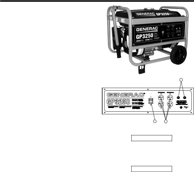
Specifications – GP1800
|
M |
H |
A |
Outlets
A (2) 5-20R 120V
Circuit Breakers
M |
(1) 20A |
|
|
Other Features
H On/Off Switch
Product Series |
GP1800 |
|
|
A/C Rated Output Watts: |
1800 |
|
|
A/C Maximum Output Watts: |
2050 |
|
|
A/C Voltage |
120VAC |
|
|
A/C Frequency |
60 Hz |
|
|
Rated 120 VAC Amperage |
7.5 |
|
|
Max 120 VAC Amperage |
8.5 |
|
|
Engine Displacement |
163cc |
|
|
Engine Type |
OHV |
|
|
Engine RPM |
3600 |
|
|
Recommended Oil |
5W30 |
|
|
Lubrication Method |
Splash Sump |
|
|
Choke Type |
Manual Lever |
|
|
Fuel Shut Off |
Manual Lever |
|
|
Idle Control |
Full Speed |
|
|
Starting Method |
Manual |
|
|
Battery |
n/a |
|
|
Battery Size |
n/a |
|
|
Low Oil Shutdown Method |
Low Level |
|
|
Start Switch Type |
On/Off Toggle |
|
|
Switch Location |
Control Panel |
|
|
Single-Point Lifting Eye |
N/A |
|
|
Fuel Gauge |
Built-In |
|
|
Fuel Tank Capacity (Gal) |
4 |
|
|
Fuel Tank Capacity (Liters) |
15.14 |
|
|
Run Time at 50% (Hours) |
14 |
|
|
Cord Set |
No |
|
|
Handle Style |
Folding |
|
|
Wheel type |
n/a |
|
|
Length (L) |
23.5 |
|
|
Width (W) |
17 |
|
|
Height (H) |
17.5 |
|
|
Extended Length (EL) |
23.5 |
|
|
Unit Weight (lbs) |
79 |
|
|
Spark Plug Type |
NGK BPR4ES |
|
or Champion |
|
RN14YC |
Spark Plug Gap |
0.028"-0.031" |
|
(0.7-0.8mm) |
Oil Capacity |
0.634 quart |
|
(0.6 liter) |
Page 2
MANUALEQUIPOSPESADOS.COM
Specifications – GP3250
Product Series |
GP3250 |
|
|
A/C Rated Output Watts: |
3250 |
|
|
A/C Maximum Output Watts: |
3750 |
|
|
A/C Voltage |
120VAC |
|
|
A/C Frequency |
60 Hz |
|
|
Rated 120 VAC Amperage |
13.5 |
|
|
Max 120 VAC Amperage |
15.6 |
|
|
Engine Displacement |
206cc |
|
|
Engine Type |
OHV |
|
|
Engine RPM |
3600 |
|
|
Recommended Oil |
5W30 |
|
|
Lubrication Method |
Splash Sump |
|
|
Choke Type |
Manual Lever |
|
|
Fuel Shut Off |
Manual Lever |
|
|
Idle Control |
Full Speed |
|
|
Starting Method |
Manual |
|
|
Battery |
n/a |
|
|
Battery Size |
n/a |
|
|
Low Oil Shutdown Method |
Low Level |
|
|
Start Switch Type |
On/Off Toggle |
|
|
Switch Location |
Control Panel |
|
|
Single-Point Lifting Eye |
N/A |
|
|
Fuel Gauge |
Built-In |
|
|
Fuel Tank Capacity (Gal) |
4 |
|
|
Fuel Tank Capacity (Liters) |
15.14 |
|
|
Run Time at 50% (Hours) |
13.5 |
|
|
Cord Set |
No |
|
|
Handle Style |
Folding |
|
|
Wheel type |
7.0" Solid Wheels |
|
|
Length (L) |
25.5 |
|
|
Width (W) |
21 |
|
|
Height (H) |
19 |
|
|
Extended Length (EL) |
39.5 |
|
|
Unit Weight (lbs) |
91 |
|
|
Spark Plug Type |
NGK BPR4ES |
|
or Champion |
|
RN14YC |
|
|
Spark Plug Gap |
0.028"-0.031" |
|
(0.7-0.8mm) |
|
|
Oil Capacity |
0.634 quart |
|
(0.6 liter) |
|
|
|
|
M |
|
H |
A |
Outlets |
|
|
A |
(4) 5-20R 120V |
|
Circuit Breakers
M |
(2) 20A |
|
|
Other Features
H On/Off Switch
Page 3

MANUALEQUIPOSPESADOS.COM
Specifications – GP5000
|
|
|
|
Product Series |
GP5000 |
|
|
|
|
A/C Rated Output Watts: |
5000 |
|
|
|
|
A/C Maximum Output Watts: |
6250 |
|
|
|
|
A/C Voltage |
120/240VAC |
|
|
|
|
A/C Frequency |
60 Hz |
|
|
|
|
Rated 120/240 VAC Amperage |
20.8 |
|
|
|
|
Max 120/240 VAC Amperage |
26.0 |
|
|
|
|
Engine Displacement |
389cc |
|
|
|
|
Engine Type |
OHV |
|
|
|
|
Engine RPM |
3600 |
|
|
|
|
Recommended Oil |
5W30 |
|
|
|
|
Lubrication Method |
Splash Sump |
|
|
A |
|
Choke Type |
Manual Lever |
B |
|
H |
Fuel Shut Off |
Manual Lever |
|
|
|
||||
|
|
|
|
Idle Control |
Full Speed |
|
|
|
|
Starting Method |
Manual |
|
|
|
|
Battery |
n/a |
|
|
|
|
Battery Size |
n/a |
|
|
|
|
Low Oil Shutdown Method |
Low Level |
|
|
|
|
Start Switch Type |
3-Position |
|
|
|
|
Switch Location |
On Engine |
|
|
|
|
Single-Point Lifting Eye |
N/A |
N |
M |
|
|
Fuel Gauge |
Built-In |
Receptacles |
|
|
Fuel Tank Capacity (Gal) |
6.6 |
|
|
|
Fuel Tank Capacity (Liters) |
24.981 |
||
A |
|
(4) 5-20R 120V |
|
||
|
|
Run Time at 50% (Hours) |
10 |
||
B |
L14-30R Twist-Lock 120/240V |
|
|||
|
Cord Set |
No |
|||
|
|
|
|
||
Circuit Breakers |
|
|
Handle Style |
Folding Interlocked |
|
|
|
Wheel type |
9.5" Solid Wheels |
||
M |
|
(2) 20A |
|
||
|
|
Length (L) |
33.5 |
||
N |
|
(2) 25A |
|
||
|
|
|
|
||
|
|
|
|
Width (W) |
26.5 |
Other Features |
|
|
Height (H) |
27.5 |
|
H |
|
Hour Meter with |
|
Extended Length (EL) |
47 |
Maintenance Reset |
|
||||
|
|
Unit Weight (lbs) |
167 |
||
|
|
|
|
||
|
|
|
|
Spark Plug Type |
NHSP F7RTC or |
|
|
|
|
|
Champion RN9YC |
|
|
|
|
Spark Plug Gap |
0.028"-0.031" |
|
|
|
|
|
(0.7-0.8mm) |
|
|
|
|
Oil Capacity |
1.16 quart |
|
|
|
|
|
(1.1 liter) |
Page 4
MANUALEQUIPOSPESADOS.COM
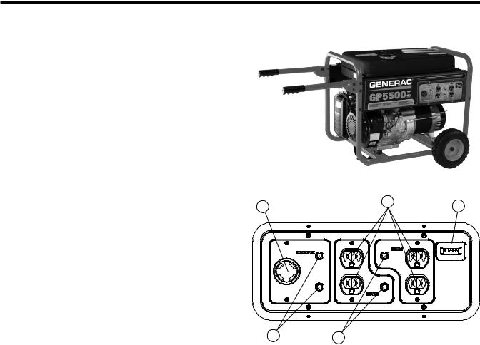
Specifications – GP5500
Product Series |
GP5500 |
|
|
A/C Rated Output Watts: |
5000 |
|
|
A/C Maximum Output Watts: |
6875 |
|
|
A/C Voltage |
120/240VAC |
|
|
A/C Frequency |
60 Hz |
|
|
Rated 120/240 VAC Amperage |
22.9 |
|
|
Max 120/240 VAC Amperage |
28.6 |
|
|
Engine Displacement |
389cc |
|
|
Engine Type |
OHV |
|
|
Engine RPM |
3600 |
|
|
Recommended Oil |
5W30 |
|
|
Lubrication Method |
Splash Sump |
|
|
Choke Type |
Manual Lever |
|
|
Fuel Shut Off |
Manual Lever |
|
|
Idle Control |
Full Speed |
|
|
Starting Method |
Manual |
|
|
Battery |
n/a |
|
|
Battery Size |
n/a |
|
|
Low Oil Shutdown Method |
Low Level |
|
|
Start Switch Type |
3-Position |
|
|
Switch Location |
On Engine |
|
|
Single-Point Lifting Eye |
N/A |
|
|
Fuel Gauge |
Built-In |
|
|
Fuel Tank Capacity (Gal) |
6.6 |
|
|
Fuel Tank Capacity (Liters) |
24.98 |
|
|
Run Time at 50% (Hours) |
10 |
|
|
Cord Set |
No |
|
|
Handle Style |
Folding Interlocked |
|
|
Wheel type |
9.5" Solid Wheels |
|
|
Length (L) |
33.5 |
|
|
Width (W) |
26.5 |
|
|
Height (H) |
27.5 |
|
|
Extended Length (EL) |
47 |
|
|
Unit Weight (lbs) |
167 |
|
|
Spark Plug Type |
NHSP F7RTC or |
|
Champion RN9YC |
|
|
Spark Plug Gap |
0.028"-0.031" |
|
(0.7-0.8mm) |
|
|
Oil Capacity |
1.16 quart |
|
(1.1 liter) |
|
|
B A H
N |
M |
|
Receptacles |
||
|
|
|
A |
(4) 5-20R 120V |
|
B |
|
|
L14-30R Twist-Lock 120/240V |
||
|
|
|
Circuit Breakers |
||
|
|
|
M |
(2) 20A |
|
N |
|
|
(2) 25A |
||
|
|
|
Other Features |
||
|
|
|
H |
Hour Meter with |
|
Maintenance Reset |
||
|
||
|
|
|
Page 5
MANUALEQUIPOSPESADOS.COM
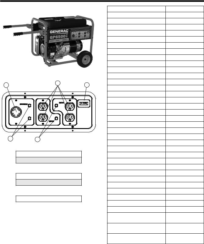
Specifications – GP6500
|
|
|
Product Series |
GP6500 |
|
|
|
A/C Rated Output Watts: |
6500 |
|
|
|
A/C Maximum Output Watts: |
8000 |
|
|
|
A/C Voltage |
120/240VAC |
|
|
|
A/C Frequency |
60 Hz |
|
|
|
Rated 120/240 VAC Amperage |
27.1 |
|
|
|
Max 120/240 VAC Amperage |
33.3 |
|
|
|
Engine Displacement |
389cc |
|
|
|
Engine Type |
OHV |
|
|
|
Engine RPM |
3600 |
|
|
|
Recommended Oil |
5W30 |
|
|
|
Lubrication Method |
Splash Sump |
B |
A |
H |
Choke Type |
Manual Lever |
|
Fuel Shut Off |
Manual Lever |
||
|
|
|
||
|
|
|
Idle Control |
Full Speed |
|
|
|
Starting Method |
Manual |
|
|
|
Battery |
n/a |
|
|
|
Battery Size |
n/a |
|
|
|
Low Oil Shutdown Method |
Low Level |
|
|
|
Start Switch Type |
3-Position |
|
|
|
Switch Location |
On Engine |
N |
M |
|
Single-Point Lifting Eye |
N/A |
|
Fuel Gauge |
Built-In |
||
|
|
|
||
Outlets |
|
Fuel Tank Capacity (Gal) |
6.6 |
|
|
|
|
||
A |
(4) 5-20R 120V |
|
Fuel Tank Capacity (Liters) |
24.98 |
B |
L14-30R Twist-Lock 120/240V |
|
Run Time at 50% (Hours) |
9 |
Circuit Breakers |
|
Cord Set |
No |
|
|
Handle Style |
Folding Interlocked |
||
M |
(2) 20A |
|
||
|
Wheel type |
9.5" Solid Wheels |
||
N |
(2) 30A |
|
||
|
Length (L) |
33.5 |
||
|
|
|
||
Other Features |
|
Width (W) |
26.5 |
|
|
|
|
||
H |
Hour Meter with Maintenance Reset |
|
Height (H) |
27.5 |
|
|
|
||
|
|
|
Extended Length (EL) |
47 |
|
|
|
Unit Weight (lbs) |
172 |
|
|
|
Spark Plug Type |
NHSP F7RTC or |
|
|
|
|
Champion RN9YC |
|
|
|
Spark Plug Gap |
0.028"-0.031" |
|
|
|
|
(0.7-0.8mm) |
|
|
|
Oil Capacity |
1.16 quart |
|
|
|
|
(1.1 liter) |
Page 6
MANUALEQUIPOSPESADOS.COM
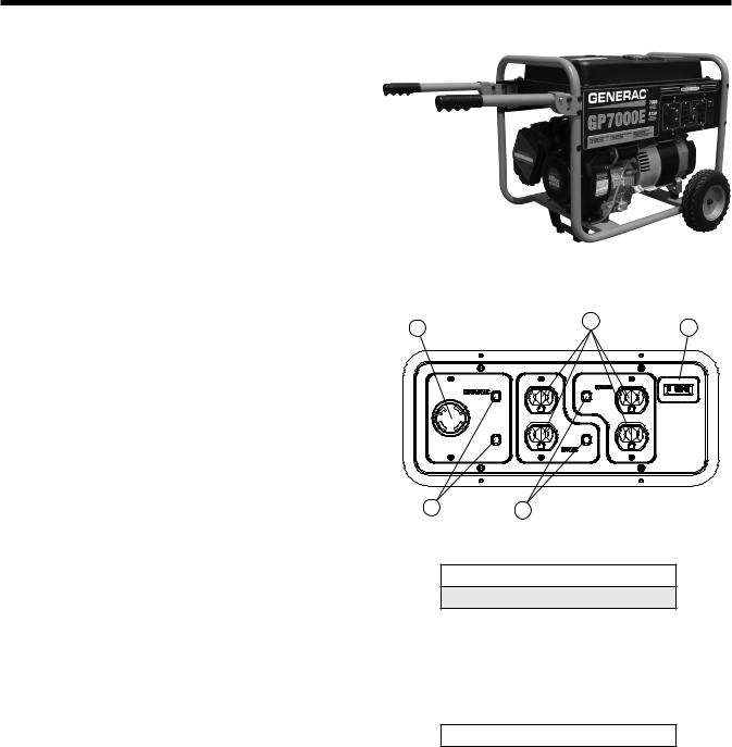
Specifications – GP7000/GP7000E
Product Series |
GP7000 |
|
|
A/C Rated Output Watts: |
7000 |
|
|
A/C Maximum Output Watts: |
8750 |
|
|
A/C Voltage |
120/240VAC |
|
|
A/C Frequency |
60 Hz |
|
|
Rated 120/240 VAC Amperage |
29.2 |
|
|
Max 120/240 VAC Amperage |
36.5 |
|
|
Engine Displacement |
410cc |
|
|
Engine Type |
OHVI |
|
|
Engine RPM |
3600 |
|
|
Recommended Oil |
5W30 |
|
|
Lubrication Method |
Full Pressure |
|
|
Choke Type |
Manual Lever |
|
|
Fuel Shut Off |
Manual Lever |
|
|
Idle Control |
Full Speed |
|
|
Starting Method GP7000 |
Manual |
|
|
Starting Method GP7000E |
Manual or Electric |
|
|
Battery Size (if equipped) |
12VDC 10 Ahr |
|
|
Low Oil Shutdown Method |
Low Pressure |
|
|
Start Switch Type |
3-Position |
|
|
Switch Location |
On Engine |
|
|
Single-Point Lifting Eye |
N/A |
|
|
Fuel Gauge |
Built-In |
|
|
Fuel Tank Capacity (Gal) |
8 |
|
|
Fuel Tank Capacity (Liters) |
30.28 |
|
|
Run Time at 50% (Hours) |
11 |
|
|
Cord Set |
No |
|
|
Handle Style |
Folding Interlocked |
|
|
Wheel type |
9.5" Solid Wheels |
|
|
Spark Plug Type |
Champion RC14YC |
|
|
Spark Plug Gap |
0.030" (0.76mm) |
|
|
Oil Capacity |
1.5 quart w/filter |
|
|
B A H
N M
Outlets
A(4) 5-20R 120V
BL14-30R Twist-Lock 120/240V
Circuit Breakers
M |
(2) 20A |
N |
|
(2) 30A |
|
|
|
Other Features
H Hour Meter with Maintenance Reset
Page 7
 Loading...