


Installation and Operating Instructions
MANUAL TRANSFER SWITCH - MODELS 6295-6296 and 6378-6380
NOTE TO INSTALLER: Please leave this guide with the consumer for future reference. READ THIS MANUAL IN ITS ENTIRETY BEFORE ATTEMPTING TO INSTALL THIS EQUIPMENT.
WARNING: Generac® transfer switches should be installed by a professional electrician familiar with electrical wiring and codes, and experienced in working with generators. Generac accepts no responsibility for accidents, damages or personal injury caused by incorrect installation. This transfer switch is intended for surface mounting INDOORS only. Our transfer switches are UL listed to UL Standard 1008 and meet the criteria of National Electrical code Article 702.6 for Optional Standby Systems. CAUTION: If using the generator and transfer switch for larger appliances, such as electric water heaters, clothes dryers, electric ranges and small air conditioners, check the labels on the appliances to be sure they do NOT exceed the rating of the generator. No appliance should have an amperage rating that exceeds the individual breaker rating in the transfer switch. CALIFORNIA PROPOSITION 65 WARNING: Engine exhaust and some of its constituents are known to the State of California to cause cancer, birth defects and other reproductive harm. This product may contain or emit chemicals known to cause cancer, birth defects and other reproductive harm.
Thank you for purchasing a Generac Transfer Switch to safely connect a portable generator to the load center in your home or business (single phase only) for standby power applications. Product features include:
•Generator and Utility feeds mechanically interlocked to prevent dangerous utility or generator back feeding – thereby avoiding property damage and serious injury to electrical workers.
•Enclosure can be flush or surface mounted indoors.
•Pre-assembled wire harness with all wires clearly marked for easy connection to the load center.
•Transfer switch can be expanded to up to 16 circuits using standard interchangeable type circuit breakers. See Step 2, Section II.
•Accommodates GFCI and Arc-Fault breakers to meet the latest NEC requirements.
•Sufficient ground and neutral termination positions for all branch circuits
•Subfeed lugs provided to feed additional downstream panels or to expand beyond 16 circuits.
•Dual wattmeters help you monitor and balance the loads on your generator, prolonging generator life.
•Safe generator connection – Install the Power Inlet Box in a convenience location outside for a quick cord connection to your generator.
•Accepts a Switched Neutral Kit (SNK). See Page 2 Note on Neutral Bonded Generators above Table 1.
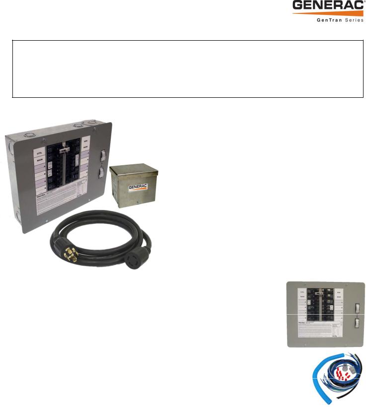
Model 6295 Kit Shown
What is Included in this Carton:
•Manual Transfer Switch with wire harness, conduit, fittings and wire connectors (10 or 12)
•Wire Harness, pre-assembled
•30 amp or 50 amp Aluminum Power Inlet Box (Models 6295-6296 only)
•10 Foot Power Cord (Models 6295-6296 only)
•Installation Manual and Warranty Registration card
Tools and Items Needed for Installation:
•1/4” nut driver, 2-1/8” hole saw (if flush mounting)
•Screwdrivers, straight blade and Phillips
•Electric drill, drill bits, wallboard saw
•Wire cutter/stripper
•Safety eye goggles
•Anchors and screws to mount transfer switch to wall/wallboard
•New, 2-pole 60 Amp or 100 Amp, 240V circuit breaker to install in main load center – same manufacturer as existing load center.
•4 gauge building wire and conduit to connect between power inlet box and transfer switch
Compatible Circuit Breaker Types:
•Siemens/Murray QT, QPH, HQP, QPF (GFCI), QPHF, QFP, QE, QEH, QAF (Arc Fault), QP (Surge Protector)
•Cutler-Hammer Series BD, BR, BQ, GFC
•Challenger Type A, C, HAGF
•Square D Series HOM (Homeline)
•GE Series THQL
Optional Items for Installation:
•Arc-fault, GFCI or Surge protection circuit breakers. If Arc-fault, GFCI or Surge protection circuit breakers are used as the branch circuit protector in the main load center, they MUST be used in the manual transfer switch. You may be able to re-use your existing AFCI, GFCI and Surge protection circuit breakers in the manual transfer switch. See list of compatible breakers.
•Wire, fittings and conduit to connect the Power Inlet Box to the transfer switch.
•White, green, black and red THHN or MTW wire, 10 AWG, 300V rated (if breaker configuration is modified or expanded.
•Switched Neutral Kit (SNK). If your portable generator has the neutral bonded to the frame of the generator AND 240V “full-power” receptacle is GFCI protected, you will need to install a SNK accessory with your transfer switch to avoid nuisance tripping of the GFCI breaker on the generator.
1
NOTE ON NEUTRAL BONDED GENERATORS: Some portable generators are intended for use on jobsites, and therefore are subject to OSHA regulations for GFCI protection on all receptacles. These "contractor grade" generators have their neutral wire bonded to the ground wire to pass OSHA inspection on job sites, and when connected to a transfer switch, this may cause nuisance tripping of the generator GFCI breaker. If you’re using a neutral bonded generator to power a house or building through a transfer switch, then determine if the neutral bond wire on the generator can be disabled without voiding the warranty, preferably by a dealer or a qualified electrician. NOTE: After this action, the generator will no longer pass OSHA inspection on job sites. Consult the manufacturer of your generator to determine if the neutral bond can be removed. If it can be disabled, then no modifications to your transfer switch installation are needed. If the neutral bond cannot be disabled or voids the generator warranty, you must install a Switched Neutral Kit (SNK) accessory with your transfer switch.
TABLE 1 - SPECIFICATIONS |
|
|
|
Model: |
6295 or 6378 |
6296 or 6380 |
|
# Circuits Provided on Transfer Switch |
10 |
12 |
|
Max # Circuits |
16 |
16 |
|
REQUIRED BREAKER FOR MAIN LOAD CENTER (not incl) |
60 amp 2-pole |
100 amp 2-pole |
|
Utility Main Breaker |
60 amp 2-pole |
100 amp 2-pole |
|
Generator Main Breaker |
30 amp 2-pole |
60 amp 2-pole |
|
Breakers Provided with Unit |
3– 15 amp 1-pole |
3– 15 amp 1-pole |
|
|
3– 20 amp 1-pole |
3– 20 amp 1-pole |
|
|
1– 20 amp 2-pole |
1– 20 amp 2-pole |
|
|
1 --30 amp 2-pole |
1 --30 amp 2-pole |
|
|
|
1 – 50 amp 2-pole |
|
Max GEN Watts |
7500 continuous / 9000 surge |
12500 continuous / 18000 surge |
|
Max GEN Amps |
30 Amps |
60 amps |
|
Voltage |
125/250 Volts |
125/250 Volts |
|
NEMA Type Enclosure |
1 – Indoor Only |
1 – Indoor Only |
|
NEMA Configuration of Male Inlet in Power Inlet Box |
NEMA L14-30 |
CS-6365 |
|
Phase |
1 |
1 |
|
Minimum Gauge Cord Size |
10/4 AWG |
6/4 AWG |
*Note: If Ground Fault Circuit Interrupters (GFCI), Arc Fault Circuit Interrupters (AFCI), or Surge Protector Circuit Breakers were used as the branch circuit protector in the main load center, they MUST be used in the transfer switch. GFCI and AFCI breakers require an isolated neutral connected from the load to the GFCI or AFCI. The load neutral needs to be connected with a wire nut to a 3-6 foot piece of white wire, run through the harness conduit to the transfer switch and connected to the "load neutral" lug or pigtail on the GFCI or ACFI breaker. Because GFCI and AFCI circuit breakers can take up more than one space, the overall maximum number of circuits may be reduced from the number shown.
STEP 1: PLANNING YOUR INSTALLATION:
1. Determine the appliances, circuits or equipment you want to operate with generator power during a power outage, such as:
• |
Refrigerator/Freezer, |
• |
Water Heater |
• |
Security System |
• |
Furnace Blower (gas/oil only) |
• |
Garage Door Opener |
• |
Sump Pump |
• |
TV / Radio |
• |
Microwave, Coffee Maker |
• |
Computer, Fax and Printer, Phone |
• |
Lighting |
• |
Well Pump |
• |
Aquarium |
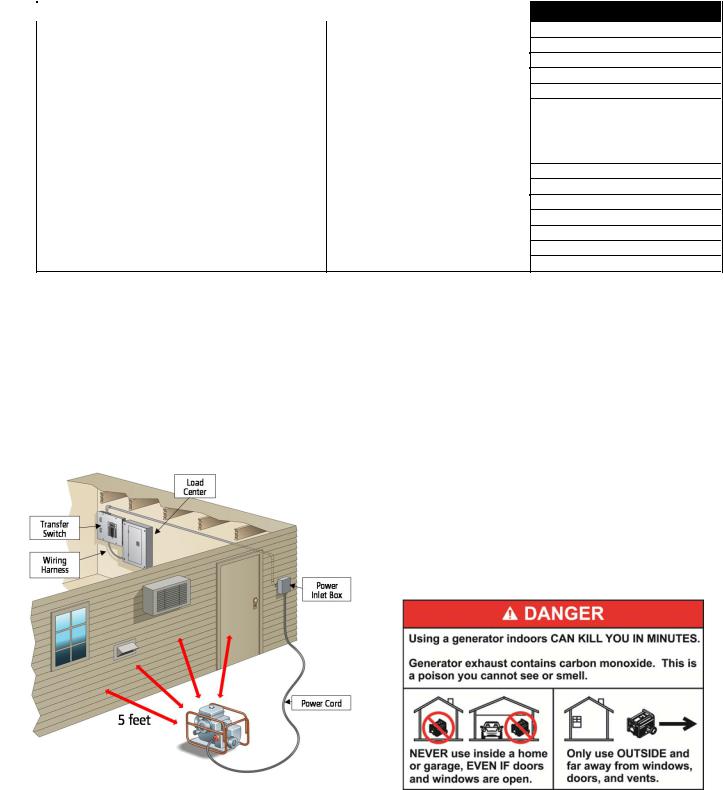
FIGURE 1: TYPICAL INSTALLATION
2.Determine the amps required for each appliance by reading the label on the appliance. IMPORTANT: No appliance should have an amperage rating that exceeds the GEN MAIN breaker rating in the transfer switch (See Table 1). The total amperage of all circuits can exceed the generator rating, but not all circuits will be able to be used concurrently.
3.Assign the circuit # in the load center to a circuit (A2, B2, etc.) in the transfer switch matching the size of the circuit breaker in the load center to the circuit breaker in the transfer switch. Once you’ve determined which circuits you want to connect and the appropriate amperage, you will be ready to begin installing your transfer switch.
4.The location of your load center/electrical panel in your home or business
will determine where the transfer switch will be installed. Refer to Figure 1. In addition to the transfer switch, this kit includes a generator cord and power inlet box. You will use the generator cord to connect your generator to the power inlet box outdoors. Whether your load center is in a basement, interior room or garage, we recommend installing power inlet box on the exterior of your house or building to avoid running generator cord through a door or window.
5.Determine where you will install the power inlet box on an exterior wall at least 5 feet from any openings (doors, windows, vents, etc.). See Figure 1.
2

TABLE 2 – CIRCUIT WORKSHEET
CIRCUIT # |
6295 or 6378 |
6296 or 6380 |
APPLIANCE OR CIRCUIT |
A1 |
NA |
50A |
|
B1 |
NA |
50A |
|
A2 |
30A |
30A |
|
B2 |
30A |
30A |
|
A3 |
NA |
20A |
|
B3 |
NA |
20A |
|
A4 |
15A |
20A |
|
B4 |
20A |
15A |
|
|
|
|
|
A5 |
15A |
20A |
|
B5 |
20A |
20A |
|
A6 |
20A |
15A |
|
B6 |
15A |
15A |
|
A7 |
20A |
NA |
|
|
|
|
|
B7 |
20A |
NA |
|
STEP 2: INSTALLATION PROCEDURE:
 HAZARDOUS VOLTAGES ARE PRESENT INSIDE TRANSFER SWITCH ENCLOSURES THAT CAN CAUSE DEATH OR SEVERE PERSONAL INJURY. FOLLOW PROPER INSTALLATION, OPERATION AND MAINTENANCE PROCEDURES TO AVOID HAZARDOUS VOLTAGES. TURN OFF THE MAIN CIRCUIT BREAKER IN THE LOAD CENTER BEFORE STARTING INSTALLATION.
I. TRANSFER SWITCH INSTALLATION:
A: Surface Mount Installation Using Power Inlet Box (included in models 6295-6296)
1.Select a location on the left or right side of the Load Center to mount transfer switch, as it is provided with 21.5” of flexible conduit. Remove the cover to the load center and the cover of the transfer switch, save the screws. Measure and cut conduit to a length and snap provided fittings on ends. Locate and remove a knockout (KO) on lower side of load center that matches the conduit fitting size on the wiring harness. After attaching the flexible conduit to both enclosures through one of the bottom or side KOs, hold the transfer switch in position against the wall on which it is to be mounted, mark the holes on the wall for the anchoring screws and anchor to wall (anchors not provided). Be sure NOT to stress the flexible conduit, as it may break. [NOTE: The Electrical Non-Metallic Tubing (ENT) provided is UL Listed and recognized by the National Electrical Code (NEC) for this application. However, some local codes and inspectors may prohibit its use in buildings that exceed (3) floors above grade.]
2.Fish the pre-assembled wire harness through the conduit. Strip each wire in the wire harness 5/8” and insert and tighten the wires to the correspondingly marked circuit breakers in the transfer switch. As you attach each marked wire to the circuit breaker, write the appliance name on the label on the transfer switch cover per the TABLE 2 CIRCUIT WORKSHEET completed in Step 1. The unmarked BLACK wires in the harness are inserted into the UTIL MAIN 2-pole breaker in the transfer switch. Attach the WHITE wire to the neutral bar located on the right side and attach the GREEN wire to the ground bar located on the left side of the transfer switch.
3.Install appropriately sized conduit, fittings and wire between the Power Inlet Box (Models 6295-6296 only) mounted on the building exterior and the transfer switch, referring to Power Inlet Box Install Instructions below. Locate and remove a KO on the right top or side of the transfer switch, pull wire into transfer switch enclosure and secure wire with fitting. . Install the green ground wire into the ground bar on the left, and install the white neutral wire into neutral bar on the right. Using provided wiring connectors, connect black wire from PIB to black wiring going to Meter “A”. Repeat for red wire from PIB to Meter “B”. Note: Models 6296 and 6380 use current transformers (CTs) connected to the meters; pass the black wire from the PIB through the hole in the CT connected to the “A” meter before connecting to the “GEN MAIN A” circuit breaker. Repeat for the red wire from the PIB, passing through the hole in the CT connected to the “B” meter before connecting to the “GEN MAIN B” circuit breaker. See FIGURE 2 WIRING DIAGRAM. Reinstall the cover to the transfer switch.
4.In the main Load Center, remove the wires from the breakers for the loads that will be relocated to the transfer switch. Cut each harness wire to a convenient length, strip off 5/8” insulation and connect to the wires removed from the breakers per TABLE 2 with the provided wire connectors. Remove two adjacent single pole breakers from which the load wires were removed and install the NEW 60A or 100A 2-pole circuit breaker (as required in the Other Items Needed section) in their place. Insert the unmarked BLACK wires from the harness into the new circuit breaker. Terminate the WHITE and GREEN wire in the harness in an open position in the Neutral and Ground bars respectively. If there is no separate ground bar, insert the GREEN wire into an open position in the NEUTRAL bar, and tighten.
5.Reinstall the cover to the load center, and turn ON the MAIN breaker in the load center. Turn ON all branch circuit breakers in both panels. Turn ON the UTIL MAIN in the transfer switch. Check that power is restored to all appliances. Transfer switch installation is complete.
B. Flush Mounting in New Construction (unfinished walls) Using Power Inlet Box (included in 6295-6296):
1.Install the transfer switch at the same time as the main load center, in adjacent wall stud openings (the transfer switch enclosure is 14.25” wide and will fit in standard 16” wall framing). Remove the transfer switch dead front cover, save the screws. Knock out the appropriate mounting slots on the sides of the enclosure and secure to framing with nails or screws; be sure the front edge of the enclosure extends forward to be flush with the thickness of the finished wallboard.
2.Mark and drill a 2 1/8” diameter hole in the stud between the main load center and the transfer switch, lining up with the lowest side KO in the load center and near the bottom center KO in the transfer switch. Remove the KO’s, cut the provided conduit to length, snap on the provided fittings to the conduit, push the conduit through the drilled hole and install the conduit assembly to the KO openings in the main load center and transfer switch.
3.Complete Section IA3 above. Cut a piece of cardboard to 14.5” x 12.5”, using the 4 screws removed in step IIA1, attach the cardboard to the front of the transfer switch.
3

4.After the walls have been finished and painted, remove the cardboard cover and complete the installation as described in Sections IA2, 4 and 5. NOTE: To simplify installation, all conductors for the branch circuits can be terminated directly into the transfer switch instead of the main load center, eliminating the need to install the harness wires between the main load center and transfer switch for each circuit.
C. Flush Mounting in Retrofit Construction (finished walls) Using Power Inlet Box (included in 6295-6296):
1.Remove the dead front cover from the main load center and the transfer switch, save the screws.
2.Determine where to install the transfer switch (keep in mind the length and flexibility of the conduit provided and where the generator wires will enter), Verify that there are no wires going thru the side of the main load center into the space where you want to mount the transfer switch. Use a “stud finder” to determine if you have at least 14.25” between the studs to mount the transfer switch. Hold the transfer switch enclosure in the desired position on the wall and mark the exact dimensions of the box. Set the enclosure aside and cut the hole in the wallboard.
3.Remove a 1” or 1-¼” KO in the lower side (towards the hole cut in Step 2) of the load center. From the inside of the main load center, drill a ¼” pilot hole through the stud in the center of the KO removed. Reach down inside the hole cut in Step 2 and drill a 2 1/8” diameter hole in the stud using the pilot hole as a guide. Remove the bottom center KO in the transfer switch, snap the fittings on the conduit, and attach the conduit assembly to the transfer switch.
4.Remove one of the KO’s on the top of the transfer switch enclosure and install an appropriately sized fitting for the incoming wires form the Power Inlet Box. Knock out the appropriate mounting slots on the sides of the transfer switch enclosure.
5.Insert the transfer switch enclosure into the hole in the wallboard, inserting conduit fitting on attached conduit assembly into the KO removed in Step 3. Fasten conduit fitting to main load center with locknut. Secure transfer switch enclosure to framing with nails or screws; be sure the front edge of the enclosure extends forward to be flush with the finished wallboard.
6.Complete Section IA2 thru 5 above.
II. EXPANDING OR RECONFIGURING YOUR TRANSFER SWITCH:
This transfer switch ships from the factory with certain popular branch circuit breaker sizes. However, the circuit breaker assortment can be modified to suit specific requirements, and this does not void the UL Listing. For example, if the 2-pole 20 amp circuit breaker is not needed, it may be removed from the panel and replaced with any combination of the following: two separate full size breakers, four tandem (half size) breakers, one full size and two tandems, or a quad breaker. If additional circuit(s) are added, the installer is responsible for providing appropriately sized wire(s) for each circuit.
III. INSTALLING THE POWER INLET BOX (Included in Models 6295-6296)
1.Remove the front cover of the Power inlet box. Remove the 3 screws that secure the flanged inlet to the bottom plate. For installations where side clearance exceeds 12” on both sides, remove the 4 screws that secure the bottom plate to the box.
2.Mount the power inlet box on the outside of the building in a convenient location (minimum 24” above grade), using the four holes provided in the back of the enclosure. Use sealant around the anchoring screws to keep water from entering the box at these mounting holes. Using approved wiring methods, install the wiring through one of the knockouts provided in the enclosure. Be sure to seal around the hole in the building where the conduit enters through the wall.
3.Extend wiring inside the power inlet box approx. 8” from the point of entrance. Attach green or bare ground wire to green lead provided in power inlet box with wire nut (provided by installer). Strip and insert incoming leads into terminals on flanged inlet. Insert white wire (neutral) into nickel-plated screw terminal or white marking on the flanged inlet.
4.Carefully fold wires into the enclosure and reattach the bottom assembly or inlet onto box with screws removed earlier. Installation is complete.
STEP 3: USING YOUR TRANSFER SWITCH:
 NEVER run portable generators indoors or in garages, basements, or sheds. Portable generators should always be used at least 5 feet away from windows, doors, vents, or any other opening. Carbon Monoxide (CO) from a generator is deadly and can kill you in minutes. Read and follow all generator directions before use.
A. Transferring from Utility Power to Generator Power:
1. Move generator outdoors. Connect male plug of Power Cord into 125/250V receptacle on the generator. Turn ON circuit breaker for the outlet plugged into. 2. Plug in female connector of the Power Cord to the Power Inlet Box. Turn all circuit breakers in the transfer switch to their OFF position.
3. Start the generator outdoors, following the procedures described in the generator’s owner’s manual.
4. Turn ON the GENERATOR MAIN circuit breaker in the transfer switch. Turn ON circuit breakers in the manual transfer switch one at a time alternating from phase “A” and phase “B”. Watch the meters as you turn on successive circuits so that the meters do not continuously exceed the maximum wattage of the generator. It may be necessary to alternate the use of larger loads (furnace motors, well pumps, freezers, etc.) to avoid overloading the generator. To promote generator life, loads should be balanced on Phase “A” and “B” so that the wattage reading on each meter is within about 1000 watts of the other.
5. Test your circuits by using the wattmeters or determine wattage from that shown on each appliance. Make a note of any excessive loads which must be removed from a given circuit during generator operation in an emergency. [Note: Wattmeters do not show power at very low levels.]
B. Transferring from Generator Power to Utility Power:
1.On the transfer switch, turn the GENERATOR MAIN breaker OFF. Then shut down the generator, following the procedures in the generator Owner’s Manual.
2.On the transfer switch, turn the UTILITY MAIN breaker ON. Then Turn ON any branch circuit breakers in the transfer switch that are OFF.
3.Unplug the power cord from the generator and the power inlet.
4.Cool off the generator and store in a dry, secured location.
To ensure that your generator will work properly when you need it, it is important to start and run your generator under load regularly and keep the tank filled with fresh fuel. Perform the above steps at least ONCE A MONTH to keep the generator properly “exercised.” It is not necessary to turn off any circuits in the MAIN load center when operating/testing the transfer switch.
4

Figure 2: WIRING DIAGRAMS: |
6295-6378 |
6296-6380 |
|
|
Model 6295 (shown below) includes a 2-pole 60 Amp breaker for the
Utility Main and a 2-pole 30 amp Generator Main.
Model 6296 includes a 2-pole 100 amp Utility Main and a 2-pole 60 amp Generator Main.
6295 / 6378 Shown
|
Protected by US Patent No. US 6,861,596 B2 |
|
Generac Power Systems, Inc. |
|
Toll Free: 1-888-GENERAC |
|
www.generac.com |
|
0197000SBY |
© 2012 Generac Power Systems, Inc. All Rights Reserved. GenTran and Generac are registered trademarks of Generac Power Systems, Inc. |
PN 500508 Rev A |
5
Instructions d'installation et d'utilisation
COMMUTATEUR DE TRANSFERT MANUEL - MODÈLES 6295-6296 ET 6378-6380
AVIS POUR L'INSTALLATEUR: Veuillez laisser ce guide à la disposition du consommateur pour qu'il s'en serve ultérieurement. VEUILLEZ LIRE CE MANUEL EN TOTALITÉ AVANT D'ESSAYER D'INSTALLER CET APPAREILLAGE. AVERTISSEMENT : Les commutateurs de transfert Generac®doivent être installés par un électricien professionnel qui se connaît bien en câbles et codes électriques et a de l'expérience avec les génératrices. Generac décline toute responsabilité pour les accidents, les dommages ou les blessures causés par une installation incorrecte. Ce commutateur de transfert sera monté en surface uniquement À L'INTÉRIEUR. Nos commutateurs de transfert sont homologués UL selon le standard UL 1008 et répondent aux critères du Code électrique national, article 702.6 portant sur les systèmes de secours secondaires. ATTENTION : Si vous utilisez le générateur et le commutateur de transfert pour des appareils plus grands, tels que les chauffe-eau électriques, les sécheuses à linge, les cuisinières électriques et les petits climatiseurs, lisez les étiquettes sur les appareils pour vérifier qu'ils ne dépassent PAS la puissance nominale du générateur. L'intensité de l'appareil ne devrait pas dépasser la puissance nominale du disjoncteur individuel du commutateur de transfert (20 ou 30 ampères). Avertissement conformément à la California Proposition 65: L'État de Californie avertit que l'échappement du moteur et certains de ses composants peuvent causer le cancer, des malformations congénitales ou autres anomalies de la reproduction. Ce produit peut contenir ou émettre des produits chimiques qui, selon l'État de Californie, peuvent causent le cancer, des malformations congénitales ou autres anomalies de la reproduction.
Nous vous remercions d'avoir acheté une commutateur de transfert Generac pour brancher un générateur portable en toute sécurité au centre de distribution de votre maison ou de votre entreprise (monophasé seulement) pour des applications à
alimentation de secours. Quelques caractéristiques du produit :
•L'alimentation de la génératrice et de l'installation de service sont verrouillées mécaniquement pour empêcher la réalimentation du circuit de service ou de la génératrice qui peut être dangereuse - et éviter ainsi tout dégât matériel et de graves blessures des électriciens.
•Le boîtier peut être encastré ou monté en surface à l'intérieur.
•Faisceau électrique prémonté avec tous les fils clairement marqués pour en faciliter le branchement au centre de distribution.
•L'on peut ajouter tout au plus 16 circuits à chaque commutateur de transfert à l'aide de disjoncteurs standard interchangeables. Voir l'étape 2, section II.
•Compatible avec les disjoncteurs GFCI et d'amorçage d'arc pour répondre aux dernières exigences de NEC.
•Positions terminales de masse et de neutre suffisantes pour tous les circuits de dérivation
•Cosses d'artère secondaire pour alimenter des panneaux descendants supplémentaires ou pour augmenter le nombre de circuits au-delà de 16.
•Des wattmètres doubles vous permettent de surveiller et équilibrer les charges de la génératrice, prolongeant ainsi sa vie.
•Raccordement de la génératrice en toute sécurité - installez la boîte d'entrée du courant dans un endroit facilement accessible à l'extérieur pour y brancher rapidement la génératrice.
•Compatible avec un bloc neutre commuté (SNK). Voir la note de la page 2 sur les génératrices liées au neutre au-dessus du tableau 1.
Le paquet contient :
•un commutateur de transfert manuel avec faisceau électrique, conduit, raccords et serre-fils (10 ou 12)
•faisceau électrique prémonté
•Boîte d'entrée d'alimentation en aluminium étanche à la pluie (modèles 6295-6296)
•cordon d'alimentation de 10 pieds (modèles 6295-6296)
•Manuel d'installation et carte de garantie
Outils et objets nécessaires pour l'installation :
•tournevis à douille de 1/4 po, scie cloche de 2-1/8 po (en cas d'encastrement)
•Tournevis, aube droite et Phillips
•Perceuse électrique, forets, scie à panneau mural
•Coupe-fil / outil à dénuder
•Lunettes de protection
•Ancrages et vis pour monter le commutateur de transfert sur le mur ou un panneau mural
•Un nouveau disjoncteur bipolaire de 60 ou 100 ampères de 240V à installer dans le centre de distribution principal - même fabricant que le centre de distribution actuel.
•Fil de bâtiment calibre 4 et conduit pour relier la boîte d'entrée d'alimentation et le commutateur de transfert
Disjoncteurs compatibles :
•Siemens/Murray QT, QPH, HQP, QPF (GFCI), QPHF, QFP, QE, QEH, QAF (amorçage d'arc), QP (protecteur contre les surtensions)
•Série BD, BR, BQ, GFC de Cutler-Hammer
•Challenger Type A, C, HAGF
•Série Square D HOM (Homeline)
•Série THQL de GE
1
 Loading...