


Generac 13 kW NG, 9 kW NG, 8 kW LP, 16 kW NG, 14 kW LP User Manual
...diagnostic repair manual
Air-Cooled Product
MODELS:
7 kW NG, 8 kW LP
9 kW NG, 10 kW LP
13 kW NG, 14 kW LP
16 kW NG, 17 kW LP
18 kW NG, 20 kW LP
a u t o m a t i c s t a n d b y g e n e r a t o r s

Electrical formulas
TO FIND |
KNOWN VALUES |
1-PHASE |
3-PHASE |
|
|
|
|
|
|
KILOWATTS (kW) |
Volts, Current, Power Factor |
E x I |
E x I x 1.73 x PF |
|
1000 |
1000 |
|||
|
|
|||
|
|
|
|
|
KVA |
Volts, Current |
E x I |
E x I x 1.73 |
|
1000 |
1000 |
|||
|
|
|||
|
|
|
|
|
AMPERES |
kW, Volts, Power Factor |
kW x 1000 |
kW x 1000 |
|
E |
E x 1.73 x PF |
|||
|
|
|||
|
|
|
|
|
WATTS |
Volts, Amps, Power Factor |
Volts x Amps |
E x I x 1.73 x PF |
|
|
|
|
|
|
NO. OF ROTOR POLES |
Frequency, RPM |
2 x 60 x Frequency |
2 x 60 x Frequency |
|
RPM |
RPM |
|||
|
|
|||
|
|
|
|
|
FREQUENCY |
RPM, No. of Rotor Poles |
RPM x Poles |
RPM x Poles |
|
2 x 60 |
2 x 60 |
|||
|
|
|||
|
|
|
|
|
RPM |
Frequency, No. of Rotor Poles |
2 x 60 x Frequency |
2 x 60 x Frequency |
|
Rotor Poles |
Rotor Poles |
|||
|
|
|||
|
|
|
|
|
kW (required for Motor) |
Motor Horsepower, Efficiency |
HP x 0.746 |
HP x 0.746 |
|
Efficiency |
Efficiency |
|||
|
|
|||
|
|
|
|
|
RESISTANCE |
Volts, Amperes |
E |
E |
|
I |
I |
|||
|
|
|||
|
|
|
|
|
VOLTS |
Ohm, Amperes |
I x R |
I x R |
|
|
|
|
|
|
AMPERES |
Ohms, Volts |
E |
E |
|
R |
R |
|||
|
|
|||
|
|
|
|
|
E = VOLTS |
I = AMPERES |
R = RESISTANCE (OHMS) |
PF = POWER FACTOR |
Contents |
|
Specifications........................................................... |
4 |
Generator................................................................. |
4 |
Engine...................................................................... |
5 |
Fuel Consumption.................................................... |
5 |
Mounting Dimensions.............................................. |
6 |
Mounting Dimensions.............................................. |
7 |
Major Features......................................................... |
8 |
PART 1 - GENERAL INFORMATION........................ |
9 |
1.1 Generator Identification.................................... |
10 |
Introduction....................................................... |
10 |
1.2 Installation Basics............................................ |
11 |
Introduction....................................................... |
11 |
Selecting A Location......................................... |
11 |
Grounding The Generator................................. |
11 |
The Fuel Supply............................................... |
11 |
The Transfer Switch / Load Center................... |
11 |
Power Source And Load Lines......................... |
13 |
System Control Interconnections...................... |
13 |
Natural Gas Fuel Interconnections................... |
13 |
1.3 Non-prepackaged Interconnections................. |
14 |
Connect a Pre-2008 Load Center Switch |
|
To a Current or Future |
|
Air-Cooled Generator................................... |
14 |
Connect a 2008 And Later Load Center |
|
Switch to a Pre-2008 |
|
Air-Cooled Generator................................... |
15 |
1.4 Preparation Before Use.................................... |
16 |
General............................................................. |
16 |
Fuel Requirements........................................... |
16 |
Fuel Consumption............................................ |
16 |
Reconfiguring The Fuel System....................... |
16 |
Engine Oil Recommendations.......................... |
18 |
1.5 Testing, Cleaning and Drying........................... |
19 |
Meters ............................................................. |
19 |
The Vom........................................................... |
19 |
Measuring AC Voltage...................................... |
19 |
Measuring DC Voltage...................................... |
19 |
Measuring AC Frequency................................. |
19 |
Measuring Current............................................ |
20 |
Measuring Resistance...................................... |
20 |
Electrical Units.................................................. |
21 |
Ohm’s Law........................................................ |
21 |
Visual Inspection.............................................. |
22 |
Insulation Resistance....................................... |
22 |
The Megohmmeter........................................... |
22 |
Stator Insulation Resistance Test (12-20 kW)...... |
23 |
Stator Insulation Resistance Test (8-10 kW)........ |
23 |
Rotor Insulation Resistance Test (8-10 kW)......... |
24 |
Rotor Insulation Resistance Test (12-20 kW)....... |
24 |
Cleaning The Generator................................... |
24 |
Drying The Generator....................................... |
24 |
1.6 Engine-Generator Protective Devices.............. |
25 |
General............................................................. |
25 |
Low Battery...................................................... |
25 |
Low Oil Pressure Shutdown............................. |
25 |
High Temperature Switch.................................. |
25 |
Overspeed Shutdown....................................... |
25 |
Rpm Sensor Failure.......................................... |
25 |
Overcrank Shutdown........................................ |
26 |
1.7 Operating Instructions...................................... |
27 |
Control Panel.................................................... |
27 |
To Select Automatic Operation......................... |
28 |
Manual Transfer To “Standby” |
|
and Manual Startup...................................... |
28 |
Manual Shutdown And |
|
Retransfer Back To “Utility”........................... |
28 |
1.8 Automatic Operating Parameters..................... |
29 |
Introduction....................................................... |
29 |
Automatic Operating Sequences...................... |
29 |
PART 2 - AC GENERATORS................................... |
31 |
2.1 Description and Components........................... |
32 |
Introduction....................................................... |
32 |
Engine-Generator Drive System....................... |
32 |
The AC Generator............................................ |
32 |
Rotor Assembly................................................ |
32 |
Stator Assembly............................................... |
33 |
Brush Holder And Brushes (12-20 kW)............ |
34 |
Other AC Generator Components.................... |
34 |
2.2 Operational Analysis........................................ |
35 |
Rotor Residual Magnetism............................... |
35 |
Field Boost (12-20 kW)..................................... |
35 |
Operation (8/10 kW)......................................... |
36 |
Operation (12-20 kW)....................................... |
36 |
2.3 Troubleshooting Flowcharts............................. |
37 |
Problem 1 – Generator Produces Zero |
|
Voltage or Residual Voltage (12-20 kW)... |
37-38 |
Problem 2 – Generator Produces Zero |
|
Voltage or Residual Voltage (8/10 kW)......... |
38 |
Problem 3 – Generator Produces |
|
Low Voltage at No-Load............................... |
39 |
Problem 4 – Generator Produces |
|
High Voltage at No-Load.............................. |
39 |
Problem 5 – Voltage and Frequency Drop |
|
Excessively When Loads are Applied.......... |
40 |
2.4 Diagnostic Tests............................................... |
41 |
Introduction....................................................... |
41 |
Safety ............................................................. |
41 |
Test 1 – Check Main Circuit Breaker................ |
41 |
Test 2 – Check AC Output Voltage................... |
41 |
Test 4 – Fixed Excitation Test/Rotor |
|
Amp Draw Test..................................... |
42 |
Test 5 – Wire Continuity (12-20 kW)................. |
43 |
Test 6 – Check Field Boost (12-20 kW)............ |
44 |
Page 1
Test 7 – Testing The Stator With A Vom |
|
(12-20 kW)........................................... |
44 |
Test 8 – Test Brushless Stator.......................... |
45 |
Test 9 – Check Capacitor................................. |
46 |
Test 10 – Test DPE Winding on |
|
Brushless units.................................... |
47 |
Test 11 – Resistance Check Of Rotor Circuit |
|
(12-20 kW)........................................... |
48 |
Test 12 – Check Brushes And Slip Rings |
|
(12-20 kW)........................................... |
48 |
Test 13 – Test Rotor Assembly(12-20 kW)....... |
49 |
Test 14 – Check AC Output Frequency............ |
49 |
Test 15 – Check and Adjust Engine Governor |
|
(Single Cylinder Units)......................... |
49 |
Test 16 – Check Stepper Motor Control |
|
(V-twin Engine Units)........................... |
50 |
Test 17 – Check And Adjust Voltage |
|
Regulator (12-20 kW)........................... |
51 |
Test 18 – Check Voltage And Frequency |
|
Under Load.......................................... |
52 |
Test 19 – Check For Overload Condition........... |
52 |
Test 20 – Check Engine Condition................... |
52 |
Test 21 – Field Flash Alternator (8-10 kW)....... |
52 |
PART 3 - TRANSFER SWITCH............................... |
55 |
3.1 Description and Components........................... |
56 |
General............................................................. |
56 |
Enclosure.......................................................... |
56 |
Transfer Mechanism......................................... |
57 |
Transfer Relay................................................... |
57 |
Neutral Lug....................................................... |
58 |
Manual Transfer Handle ................................... |
58 |
Terminal Block ................................................. |
58 |
Fuse Holder...................................................... |
59 |
3.2 Operational Analysis........................................ |
60 |
Operational Analysis......................................... |
60 |
Utility Source Voltage Available ....................... |
62 |
Utility Source Voltage Failure ........................... |
63 |
Transfer To Standby.......................................... |
64 |
Transfer To Standby.......................................... |
65 |
Utility Restored................................................. |
66 |
Utility Restored, Transfer Switch De-energized.... |
67 |
Utility Restored, Retransfer Back To Utility....... |
68 |
Transfer Switch In Utility................................... |
69 |
3.3 – Troubleshooting Flowcharts.......................... |
70 |
Introduction To Troubleshooting........................ |
70 |
Problem 7 – In Automatic Mode, |
|
No Transfer to Standby................................. |
70 |
Problem 8 – In Automatic Mode, Generator |
|
Starts When Loss of Utility Occurs, |
|
Generator Shuts Down When Utility |
|
Returns But There Is No Retransfer To Utility |
|
Power / or Generator Transfers to Standby |
|
During Exercise Or In Manual Mode............ |
71 |
Problem 9 – Blown F1 or F2 Fuse................ |
71 |
Problem 10 – Units Starts And Transfer |
|
Occurs When Utility Power Is On................. |
72 |
Problem 11 – No Battery Charge |
|
(Pre-Packed Load Center)............................ |
73 |
Problem 12 – No Battery Charge |
|
(RTSN & RTSE Transfer Switch).................. |
73 |
Problem 13 – No Battery Charge |
|
(Gen-Ready Load Center)............................ |
73 |
Problem 14 – No Battery Charge |
|
(Load Shed Transfer Switch)........................ |
73 |
3.4 Diagnostic Tests............................................... |
74 |
General............................................................. |
74 |
Test 26 – Check Voltage at |
|
Terminal Lugs E1, E2........................... |
74 |
Test 27 – Check Manual Transfer Switch |
|
Operation............................................. |
75 |
Test 28 – Check 23 And 15B |
|
Wiring/Connections.............................. |
76 |
Test 29 – Test Transfer Relay TR...................... |
77 |
Test 30 – Standby Control Circuit..................... |
78 |
Test 31 – Check Wire 23................................... |
78 |
Test 32 – Utility Control Circuit......................... |
80 |
Test 33 – Test Limit Switch SW2 and SW3....... |
82 |
Test 34 – Check Fuses F1 and F2.................... |
82 |
Test 35 – Check N1 and N2 Wiring................... |
83 |
Test 36 – Check N1 and N2 Voltage................. |
83 |
Test 37 – Check Utility Sensing Voltage |
|
at the Circuit Board.............................. |
84 |
Test 38 – Check Utility Sense Voltage.............. |
84 |
Test 39 – Check Voltage at |
|
Terminal Lugs N1, N2.......................... |
84 |
Test 40 – Check Battery Charger Supply |
|
Voltage “Pre-Wire Load Center”........... |
86 |
Test 41 – Check Battery Charger Output |
|
Voltage “Pre-Wire Load Center”........... |
86 |
Test 42 – Check Wire 0 and Wire15B |
|
“Pre-Wire Load Center”........................ |
86 |
Test 43 – Check Battery Charger |
|
Supply Voltage |
|
“RTSN & RTSE Transfer Switch”.......... |
87 |
Test 44 – Check Battery Charger |
|
Output Voltage |
|
“RTSN & RTSE Transfer Switch”.......... |
87 |
Test 45 – Check Wire 0/ |
|
“RTSN & RTSE Transfer Switch”......... |
87 |
Test 46 – Check Battery Charger |
|
Supply Voltage |
|
“GenReady Load Center”..................... |
90 |
Test 47 – Check Battery Charger |
|
Output Voltage |
|
“GenReady Load Center”..................... |
90 |
Test 48 – Check Wire 0/15B |
|
“GenReady Load Center”..................... |
90 |
Test 49 – Check Battery Charger |
|
Supply Voltage |
|
“Load Shed Transfer Switch”................ |
92 |
Test 50 – Check Battery Charger |
|
Output Voltage |
|
“Load Shed Transfer Switch”................ |
92 |
Test 51 – Check Wire 0 and Wire 15B |
|
“Load Shed Transfer Switch”................ |
94 |
Page 2
PART 4 - DC CONTROL.......................................... |
95 |
4.1 Description and Components........................... |
96 |
General............................................................. |
96 |
Terminal Strip / Interconnection Terminal......... |
96 |
Circuit Board..................................................... |
96 |
Auto-Off-Manual Switch.................................... |
96 |
7.5 Amp Fuse................................................... |
96 |
Menu System Navigation................................ |
102 |
4.2 Operational Analysis...................................... |
104 |
Introduction..................................................... |
104 |
Utility Source Voltage Available...................... |
104 |
Initial Dropout of Utility Source Voltage.......... |
106 |
Utility Voltage Dropout and |
|
Engine Cranking................................ |
108 |
Engine Startup and Running.......................... |
110 |
Initial Transfer to the “Standby” Source........... |
112 |
Utility Voltage Restored / |
|
Re-transfer to Utility........................... |
114 |
Engine Shutdown........................................... |
116 |
4.3 Troubleshooting Flowcharts........................... |
118 |
Problem 15 – Engine Will Not Crank |
|
When Utility Power Source Fails................ |
118 |
Problem 16 – Engine Will Not Crank When |
|
AUTO-OFF-MANUAL Switch |
|
is Set to “MANUAL..................................... |
118 |
Problem 17 – Engine Cranks |
|
but Won’t Start............................................ |
119 |
Problem 18 – Engine Starts Hard and |
|
Runs Rough / Lacks Power / Backfires...... |
120 |
Problem 19 – Shutdown Alarm / |
|
Fault Occurred............................................ |
121 |
Problem 20 – 7.5 Amp Fuse (F1) Blown...... |
122 |
Problem 21 – Generator Will Not Exercise... |
122 |
Problem 22 – No Low Speed Exercise........ |
122 |
4.4 Diagnostic Tests............................................. |
123 |
Introduction .................................................... |
123 |
Test 56 – Check Position Of |
|
Auto-Off- Manual Switch ................... |
123 |
Test 57 – Try a Manual Start .......................... |
123 |
Test 58 – Auto-Off-Manual Switch |
|
(V-Twin Only)...................................... |
123 |
Test 59 – Test Auto Operations....................... |
124 |
Test 60 – Check 7.5 Amp Fuse...................... |
124 |
Test 61 – Check Battery................................. |
124 |
Test 62 – Check Wire 56 Voltage.................... |
126 |
Test 63 – Test Starter Contactor Relay |
|
(V-twin Only)...................................... |
126 |
Test 64 – Test Starter Contactor |
|
(Single Cylinder Engine).................... |
127 |
Test 65 – Test Starter Motor........................... |
128 |
Test 66 – Check Fuel Supply and Pressure... |
130 |
Test 67 – Check Circuit Board |
|
Wire 14 Output................................... |
131 |
Test 68 – Check Fuel Solenoid....................... |
132 |
Test 69 – Check Choke Solenoid.................... |
132 |
Test 70 – Check for Ignition Spark.................. |
134 |
Test 71 – Check Spark Plugs......................... |
136 |
Test 72 – Check Engine / Cylinder Leak |
|
Down Test / Compression Test........... |
136 |
Test 73 – Check Shutdown Wire..................... |
137 |
Test 74 – Check and Adjust |
|
Ignition Magnetos............................... |
138 |
Test 75 – Check Oil Pressure Switch |
|
and Wire 86........................................ |
141 |
Test 76 – Check High Oil |
|
Temperature Switch........................... |
142 |
Test 77 – Check and Adjust Valves................. |
142 |
Test 78 – Check Wire 18 Continuity................ |
143 |
Test 79 – Test Exercise Function.................... |
144 |
Test 80 – Check Cranking and |
|
Running Circuits................................. |
144 |
Test 81 – Check to see if Low Speed |
|
Function is enabled............................ |
146 |
Test 82 – Check operation of the |
|
Choke Solenoid.................................. |
146 |
PART 5 - OPERATIONAL TESTS ......................... |
147 |
5.1 System Functional Tests................................ |
148 |
Introduction..................................................... |
148 |
Manual Transfer Switch Operation.................. |
148 |
Electrical Checks............................................ |
148 |
Generator Tests Under Load.......................... |
149 |
Checking Automatic Operation....................... |
150 |
Setting The Exercise Timer............................. |
150 |
PART 6 - DISASSEMBLY...................................... |
151 |
6.1 Major Disassembly......................................... |
152 |
Front Engine Access....................................... |
152 |
Major Disassembly......................................... |
156 |
Torque Requirements |
|
(Unless Otherwise Specified)............. |
162 |
PART 7 - ELECTRICAL DATA............................... |
163 |
Wiring Diagram, 8 kW Home Standby................. |
164 |
Schematic, 8 kW Home Standby......................... |
166 |
Wiring Diagram, 10 kW Home Standby............... |
168 |
Schematic, 10 kW Home Standby....................... |
170 |
Wiring Diagram, 14 kW Home Standby............... |
172 |
Schematic, 14 kW Home Standby....................... |
174 |
Wiring Diagram, 17 kW Home Standby............... |
176 |
Schematic, 17 kW Home Standby....................... |
178 |
Wiring Diagram, 20 kW Home Standby............... |
180 |
Schematic, 20 kW Home Standby....................... |
182 |
Wiring Diagram, Home Standby Transfer Switch, |
|
9/10/12/16 Circuit................................................. |
184 |
Schematic, Home Standby Transfer Switch, |
|
9/10/12/16 Circuit................................................. |
186 |
Page 3

Specifications
Generator
Unit |
8 kW |
|
10 kW |
12 kW |
|
14 kW |
16 kW |
|
17 kW |
20 kW |
|
|
|
|
|
|
|
|
|
|
|
Rated Max. Continuous |
7,000 NG |
|
9,000 NG |
12,000 NG |
|
13,000 NG |
16,000 NG |
|
16,000 NG |
18,000 NG |
Power Capacity (Watts*) |
8,000 LP |
|
10,000 LP |
12,000 LP |
|
14,000 LP |
16,000 LP |
|
17,000 LP |
20,000 LP |
|
|
|
|
|
|
|
|
|
|
|
Rated Voltage |
|
|
|
|
120/240 |
|
|
|
|
|
|
|
|
|
|
|
|
|
|
|
|
Rated Voltage at No-Load |
|
|
|
|
|
|
|
|
|
|
(NG) |
220-235 |
|
|
|
|
247-249 |
|
|
|
|
|
|
|
|
|
|
|
|
|
|
|
Rated Max. Continuous Load |
|
|
|
|
|
|
|
|
|
|
Current (Amps) |
|
|
|
|
|
|
|
|
|
|
120 Volts** (NG/LP) |
58.3/66.6 |
|
75.0/83.3 |
100.0/100.0 |
|
108.3/116.6 |
133.3/133.3 |
|
133.3/141.6 |
150.0/166.6 |
240 Volts (NG/LP) |
29.2/33.3 |
|
37.5/41.6 |
50.0/50.0 |
|
54.2/58.3 |
66.6/66.6 |
|
66.6/70.8 |
75.0/83.3 |
|
|
|
|
|
|
|
|
|
|
|
Main Line Circuit Breaker |
35 Amp |
|
45 Amp |
50 Amp |
|
60 Amp |
65 Amp |
|
65 Amp |
100 Amp |
|
|
|
|
|
|
|
|
|
|
|
Circuits*** 50A, 240V |
- |
|
- |
- |
|
1 |
1 |
|
1 |
- |
|
|
|
|
|
|
|
|
|
|
|
40A, 240V |
- |
|
- |
1 |
|
1 |
1 |
|
1 |
- |
|
|
|
|
|
|
|
|
|
|
|
30A, 240V |
1 |
|
1 |
1 |
|
- |
- |
|
- |
- |
|
|
|
|
|
|
|
|
|
|
|
20A, 240V |
- |
|
1 |
- |
|
1 |
1 |
|
1 |
- |
|
|
|
|
|
|
|
|
|
|
|
20A, 120V |
1 |
|
3 |
3 |
|
4 |
5 |
|
5 |
- |
|
|
|
|
|
|
|
|
|
|
|
15A, 120V |
5 |
|
3 |
5 |
|
4 |
5 |
|
5 |
- |
|
|
|
|
|
|
|
|
|
|
|
Phase |
|
|
|
|
1 |
|
|
|
|
|
|
|
|
|
|
|
|
|
|
|
|
Number of Rotor Poles |
|
|
|
|
2 |
|
|
|
|
|
|
|
|
|
|
|
|
|
|
|
|
Rated AC Frequency |
|
|
|
|
|
60 Hz |
|
|
|
|
|
|
|
|
|
|
|
|
|
|
|
Power Factor |
|
|
|
|
1 |
|
|
|
|
|
|
|
|
|
|
|
|
|
|
|
|
Battery Requirement |
Group 26R, 12 |
|
|
|
|
|
|
|
|
|
|
Volts and 350 CCA |
|
|
|
Group 26R, 12 Volts and 525 CCA Minimum |
|
|
|||
|
Minimum |
|
|
|
|
|
|
|
|
|
|
|
|
|
|
|
|
|
|
|
|
Weight (unit only in lbs.) |
340 |
|
387 |
439 |
|
439 |
455 |
|
455/421 |
450 |
|
|
|
|
|
|
|
|
|
|
|
Enclosure |
Steel |
|
Steel |
Steel |
|
Steel |
Steel |
|
Steel/Aluminum |
Aluminum |
|
|
|
|
|
|
|
|
|
|
|
Normal Operating Range |
|
|
|
-20° F (-28.8° C) to 77° F (25° C) |
|
|
||||
|
|
|
|
|
|
|
|
|
|
|
*Maximum wattage and current are subject to and limited by such factors as fuel Btu content, ambient temperature, altitude, engine power and condition, etc. Maximum power decreases about 3.5 percent for each 1,000 feet above sea level; and also will decrease about 1 percent for each 6 C (10 F) above 16 C (60 F) ambient temperature.
**Load current values shown for 120 volts are maximum TOTAL values for two separate circuits. The maximum current in each circuit must not exceed the value stated for the 240 volts.
***Circuits to be moved must be protected by same size breaker. For example, a 15 amp circuit in the main panel must be a 15 amp circuit in the transfer switch.
Stator Winding Resistance Values / Rotor Resistance
|
8 kW |
10 kW |
12 kW |
14 kW |
16 kW |
17 kW |
20 kW |
Power Winding: Across 11 & 22 |
0.123-0.1439 |
0.090-0.105 |
0.100-0.116 |
0.100-0.116 |
0.074-0.086 |
0.074-0.086 |
0.0415-0.0483 |
|
|
|
|
|
|
|
|
Power Winding: Across 33 & 44 |
0.123-0.1439 |
0.090-0.105 |
0.100-0.116 |
0.100-0.116 |
0.074-0.086 |
0.074-0.086 |
0.0415-0.0483 |
|
|
|
|
|
|
|
|
Excitation Winding: Across 2 & 6 |
0.776-0.902 |
0.511-0.594 |
0.876-1.018 |
0.876-1.018 |
0.780-0.906 |
0.780-0.906 |
0.731-0.850 |
|
|
|
|
|
|
|
|
Rotor Resistance |
3.01-3.49 |
3.22-3.74 |
7.96-9.25 |
7.96-9.25 |
8.79-10.21 |
8.79-10.21 |
10.02-11.65 |
|
|
|
|
|
|
|
|
Page 4
|
|
|
|
|
|
|
Specifications |
|
|
|
|
|
|
|
|
|
|
|
|
|
|
|
|
|
|
|
|
|
|
|
|
|
|
|
|
|
|
|
|
Engine |
|
|
|
|
|
|
|
|
|
|
|
|
|
|
Model |
8 kW |
|
10 kW |
|
12/14/16/17 kW |
|
20 kW |
|
|
|
|
|
|
|
|
|
|
Type of Engine |
GH-410 |
|
GT-530 |
|
GT-990 |
|
GT-999 |
|
|
|
|
|
|
|
|
|
|
Number of Cylinders |
1 |
|
2 |
|
2 |
|
2 |
|
|
|
|
|
|
|
|
|
|
Rated Horsepower @ 3,600 rpm |
14.8 |
|
18 |
|
32 |
|
34 |
|
|
|
|
|
|
|
|
|
|
Displacement |
407cc |
|
530cc |
|
992cc |
|
999cc |
|
|
|
|
|
|
|
|
|
|
Cylinder Block |
|
|
Aluminum w/Cast Iron Sleeve |
|
|
||
|
|
|
|
|
|
|
||
|
Valve Arrangement |
|
|
Overhead Valves |
|
|
||
|
|
|
|
|
|
|
||
|
Ignition System |
|
|
Solid-state w/Magneto |
|
|
||
|
|
|
|
|
|
|
|
|
|
Recommended Spark Plug |
RC14YC |
|
BPR6HS |
|
RC14YCA |
|
RC12YC |
|
|
|
|
|
|
|
|
|
|
Spark Plug Gap |
0.76 mm (0.030 inch) |
|
0.76 mm (0.030 inch) |
|
1.02 mm (0.040 inch) |
|
1.02 mm (0.040 inch) |
|
|
|
|
|
|
|
|
|
|
Compression Ratio |
9.4:1 |
|
9.5:1 |
|
9.5:1 |
|
9.5:1 |
|
|
|
|
|
|
|
|
|
|
Starter |
|
|
12 VDC |
|
|
|
|
|
|
|
|
|
|
|
|
|
|
Oil Capacity Including Filter |
Approx. 1.5 Qts |
|
Approx. 1.8 Qts |
|
Approx. 1.9 Qts |
|
Approx. 1.9 Qts |
|
|
|
|
|
|
|
|
|
|
Recommended Oil Filter |
|
|
Part # 070185F |
|
|
||
|
|
|
|
|
|
|
|
|
|
Recommended Air Filter |
Part # 0G3332 |
|
Part # 0E9581 |
|
Part # 0C8127 |
|
Part # 0G5894 |
|
|
|
|
|
|
|
|
|
|
Operating RPM |
|
3,600 |
|
|
|
||
|
|
|
|
|
|
|
|
|
|
|
|
|
|
|
|
|
|
|
|
|
Fuel Consumption |
|
|
|
||
|
Model # |
|
Natural Gas* |
|
|
LP Vapor** |
||
|
|
|
|
|
|
|
|
|
|
|
1/2 Load |
|
Full Load |
|
1/2 Load |
|
Full Load |
|
|
|
|
|
|
|
|
|
|
7/8 kW |
77 |
|
140 |
|
0.94/34 |
|
1.68/62 |
|
|
|
|
|
|
|
|
|
|
9/10 kW |
102 |
|
156 |
|
1.25/46 |
|
1.93/70 |
|
|
|
|
|
|
|
|
|
|
12/12 kW |
152 |
|
215 |
|
1.53/56 |
|
2.08/76 |
|
|
|
|
|
|
|
|
|
|
13/14 kW |
156 |
|
220 |
|
1.56/58 |
|
2.30/84 |
|
|
|
|
|
|
|
|
|
|
16/16 kW |
183 |
|
261 |
|
1.59/58 |
|
2.51/91 |
|
|
|
|
|
|
|
|
|
|
16/17 kW |
183 |
|
261 |
|
1.61/59 |
|
2.57/94 |
|
|
|
|
|
|
|
|
|
|
18/20 kW |
206 |
|
294 |
|
1.89/69 |
|
2.90/106 |
|
|
|
|
|
|
|
|
|
* Natural gas is in cubic feet per hour.
**LP is in gallons per hour/cubic feet per hour.
Values given are approximate.
Page 5
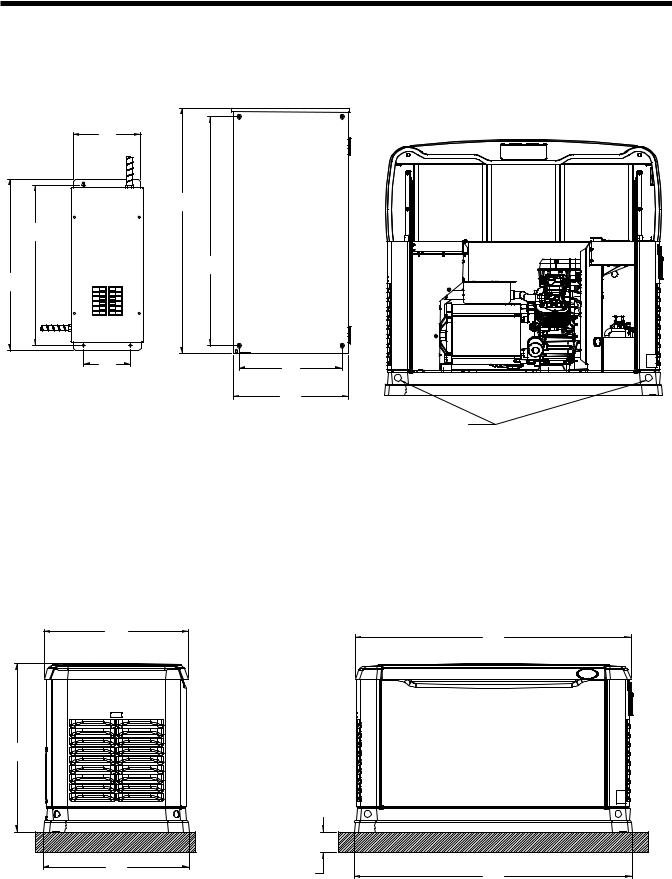
Specifications
Mounting Dimensions
299
[11.8]
1079.5
[42.5]
698
[27.5]
997
[39.3]
747
[29.4]
207 |
454 |
|
[8.2] |
||
[17.9] |
||
|
||
|
508 |
|
|
[20.0] |
TRANSFER |
TRANSFER |
SWITCH |
|
8KW - 17KW |
SWITCH |
(IF SUPPLIED) |
20KW |
|
(IF SUPPLIED) |
Ø30.2 [Ø1.2] LIFTING HOLES 4 CORNERS
"DO NOT LIFT BY ROOF"
637.6 |
[25.1] |
731.9
[28.8]
642 |
[25.3] |
LEFT SIDE VIEW
1218 |
[47.9] |
76.2 [3.0] |
1226 |
PEA GRAVEL |
[48.3] |
MINIMUM |
|
FRONT VIEW
Page 6
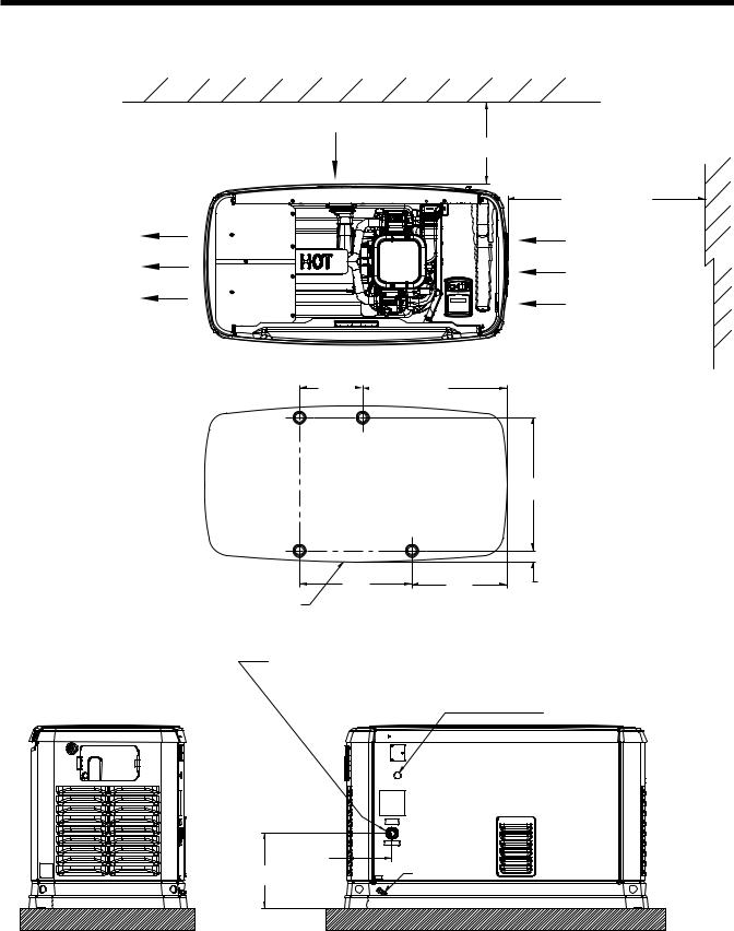
Specifications
AIR OUTLET
RIGHT SIDE VIEW
Mounting Dimensions
AIR INTAKE
457.2 |
MINIMUM DISTANCE |
|
[18.0] |
||
|
||
|
914 [36.0] |
|
|
MINIMUM OPEN AREA |
|
|
ON SIDES AND FRONT |
|
|
AIR INTAKE |
250.0575.3
[9.8] |
|
[22.7] |
530.0 |
HOLE LOCATIONS FOR |
|
[20.9] |
||
OPTIONAL MOUNTING TO |
||
|
||
|
A CONCRETE PAD |
446.6 |
378.7 |
44.8 |
[17.6] |
[14.9] |
[1.8] |
FRONT OF UNIT
|
FUEL INLET - 12-20KW (1/2" NPT) |
|
8 & 10KW (3/4" NPT) - USE SUPPLIED ADAPTER |
|
REQUIRED FUEL PRESSURE: NATURAL GAS = 5-7" WATER COLUMN |
|
LIQUID PROPANE (VAPOR) = 10-12" WATER COLUMN |
|
CABLE ACCESS HOLE |
|
178.9 |
244.4 |
[7.0] |
GROUNDING LUG |
|
[9.6] |
|
REAR VIEW
Page 7
Specifications
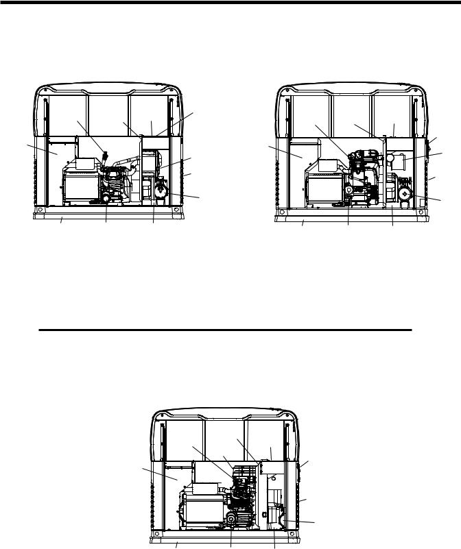
Major Features
8kW, Single Cylinder, GH-410 Engine |
|
10kW, V-twin, GT-530 Engine |
||||
(door removed) |
|
(door removed) |
||||
Oil |
Data Label |
Control |
Circuit |
|
|
|
Breaker |
Oil |
Data Label |
Control |
|||
Dipstick |
(see sample) |
Panel |
|
Dipstick |
(see sample) |
Panel |
|
|
|
|
|||
|
|
|
|
|
|
Circuit |
Exhaust |
|
|
|
Exhaust |
|
Breaker |
|
|
|
|
|
||
Enclosure |
|
|
Air Filter |
Enclosure |
|
Air |
|
|
|
|
|||
|
|
|
|
|
Filter |
|
|
|
|
|
|
|
|
|
|
|
Fuel Inlet |
|
|
Fuel Inlet |
|
|
|
(back) |
|
|
|
|
|
|
|
|
(back) |
|
|
|
|
|
|
|
|
|
|
|
Fuel |
|
|
Fuel |
|
|
|
Regulator |
|
|
|
|
|
|
|
|
Regulator |
|
|
|
|
|
|
|
|
Composite Base |
Oil Filter |
Battery Compartment |
Composite Base |
Oil Filter |
Battery Compartment |
|
|
|
|
|
|||
Figure 1.3 – 12, 14, 16, 17 and 20kW, V-twin,
GT-990/GT-999 Engine (door removed)
|
Data Label |
|
|
Oil |
(see sample) |
Control |
|
Dipstick |
|
Panel |
Circuit Breakers |
|
Air Filter |
|
GFCI Outlet |
|
|
(All 17 & 20kW) |
|
|
|
|
|
Exhaust |
|
|
|
Enclosure |
|
|
|
|
|
|
Fuel Inlet |
|
|
|
(back) |
|
|
|
Fuel |
|
|
|
Regulator |
Composite Base |
Oil Filter |
Battery Compartment |
|
Page 8
PART 1
GENERAL
INFORMATION
Air-cooled, Automatic |
|
Standby Generators |
|
1.1 Generator Identification.................................... |
10 |
Introduction....................................................... |
10 |
1.2 Installation Basics............................................ |
11 |
Introduction....................................................... |
11 |
Selecting A Location......................................... |
11 |
Grounding The Generator................................. |
11 |
The Fuel Supply............................................... |
11 |
The Transfer Switch / Load Center................... |
11 |
Power Source And Load Lines......................... |
13 |
System Control Interconnections...................... |
13 |
Natural Gas Fuel Interconnections................... |
13 |
1.3 Non-prepackaged Interconnections................. |
14 |
Connect a Pre-2008 Load Center Switch |
|
To a Current or Future |
|
Air-Cooled Generator................................... |
14 |
Connect a 2008 And Later Load Center |
|
Switch to a Pre-2008 |
|
Air-Cooled Generator................................... |
15 |
1.4 Preparation Before Use.................................... |
16 |
General............................................................. |
16 |
Fuel Requirements........................................... |
16 |
Fuel Consumption............................................ |
16 |
Reconfiguring The Fuel System....................... |
16 |
Engine Oil Recommendations.......................... |
18 |
1.5 Testing, Cleaning and Drying........................... |
19 |
Meters ............................................................. |
19 |
The Vom........................................................... |
19 |
Measuring AC Voltage...................................... |
19 |
Measuring DC Voltage...................................... |
19 |
Measuring AC Frequency................................. |
19 |
Measuring Current............................................ |
20 |
Table of contents |
|
|
Part |
Title |
Page |
|
|
|
1.1 |
Generator Identification |
10 |
|
|
|
1.2 |
Installation Basics |
11 |
|
|
|
1.3 |
Non-Prepackaged |
14 |
|
Interconnections |
|
|
|
|
1.3 |
Preparation Before Use |
16 |
|
|
|
1.4 |
Testing, Cleaning and Drying |
18 |
|
|
|
1.5 |
Engine-Generator Protective |
25 |
|
Devices |
|
1.6 |
Operating Instructions |
27 |
1.7 |
Automatic Operating |
29 |
|
Parameters |
|
|
|
|
Measuring Resistance...................................... |
20 |
Electrical Units.................................................. |
21 |
Ohm’s Law........................................................ |
21 |
Visual Inspection.............................................. |
22 |
Insulation Resistance....................................... |
22 |
The Megohmmeter........................................... |
22 |
Stator Insulation Resistance Test (12-20kW).... |
23 |
Stator Insulation Resistance Test (8-10kW)...... |
23 |
Rotor Insulation Resistance Test (8-10kW)...... |
24 |
Rotor Insulation Resistance Test (12-20kW).... |
24 |
Cleaning The Generator................................... |
24 |
Drying The Generator....................................... |
24 |
1.6 Engine-Generator Protective Devices.............. |
25 |
General............................................................. |
25 |
Low Battery...................................................... |
25 |
Low Oil Pressure Shutdown............................. |
25 |
High Temperature Switch.................................. |
25 |
Overspeed Shutdown....................................... |
25 |
Rpm Sensor Failure.......................................... |
25 |
Overcrank Shutdown........................................ |
26 |
1.7 Operating Instructions...................................... |
27 |
Control Panel.................................................... |
27 |
To Select Automatic Operation......................... |
28 |
Manual Transfer To “Standby” |
|
and Manual Startup...................................... |
28 |
Manual Shutdown And |
|
Retransfer Back To “Utility”........................... |
28 |
1.8 Automatic Operating Parameters..................... |
29 |
Introduction....................................................... |
29 |
Automatic Operating Sequences...................... |
29 |
Page 9
Section 1.1 |
Part 1 |
|
Generator Identification |
||
|
||
|
|
General information
Introduction
This Diagnostic Repair Manual has been prepared especially for the purpose of familiarizing service personnel with the testing, troubleshooting and repair of air-cooled, automatic standby generators. Every effort has been expended to ensure that information and instructions in the manual are both accurate and current. However, changes, alterations or other improvements may be made to the product at any time without prior notification.
The manual has been divided into PARTS. Each PART has been divided into SECTIONS. Each SECTION consists of two or more SUBSECTIONS.
It is not our intent to provide detailed disassembly and reassemble instructions in this manual. It is our intent to (a) provide the service technician with an understanding of how the various assemblies and systems work, (b) assist the technician in finding the cause of malfunctions, and (c) effect the expeditious repair of the equipment.
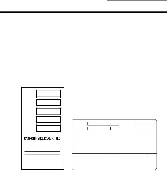
Item Number:
Many home standby generators are manufactured to the unique specifications of the buyer. The Model Number identifies the specific generator set and its unique design specifications.
Serial Number:
Used for warranty tracking purposes.
Item # |
0055555 |
|
|
|
|
|
Serial |
1234567 |
|
|
|
|
|
Volts |
120/240 AC |
|
|
|
|
|
Amps |
108.3/108.3 |
MODEL # |
|
WATTS |
13000 |
|
|
|
0055555 |
||||
Watts |
13000 |
SERIAL # |
1234567 |
VOLTS |
120/240 AC |
|
1 PH, 60 HZ, RPM 3600 |
|
|
AMPS |
108.3/108.3 |
||
|
1PH, 60Hz, 3600 RPM, CLASS F INSULATION |
|||||
|
|
|
||||
CLASS F INSULATION |
|
RAINPROOF ENCLOSURE FITTED |
|
|||
|
RATED AMBIENT TEMP - 40°C |
|
||||
MAX OPERATING AMBIENT |
|
|
||||
FOR STANDBY SERVICE, NEUTRAL FLOATING |
||||||
TEMP - 120F/49C |
||||||
FOR STANDBY SERVICE |
|
|
|
|
||
NEUTRAL FLOATING |
Model Number - |
|
Serial Number - |
|
||
MAX LOAD UNBALANCED - 50% |
|
|
|
|
||
Figure 1. Typical Data Plates
Page 10
General information |
Part 1 |
Section 1.2 |
|
Installation basics |
|||
|
|
||
|
|
|
Introduction
Information in this section is provided so that the service technician will have a basic knowledge of installation requirements for home standby systems. Problems that arise are often related to poor or unauthorized installation practices.
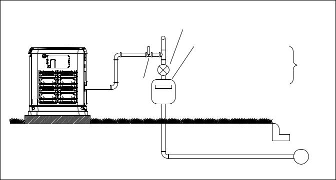
A typical home standby electric system is shown in Figure 1 (next page). Installation of such a system includes the following:
•Selecting a Location
•Grounding the generator.
•Providing a fuel supply.
•Mounting the load center.
•Connecting power source and load lines.
•Connecting system control wiring.
•Post installation tests and adjustments.
Selecting A Location
Install the generator set as close as possible to the electrical load distribution panel(s) that will be powered by the unit, ensuring that there is proper ventilation for cooling air and exhaust gases. This will reduce wiring and conduit lengths. Wiring and conduit not only add to the cost of the installation, but excessively long wiring runs can result in a voltage drop.
Control system interconnections between the transfer switch and generator consist of N1 and N2, and leads 23, 15B and 0. Control system interconnection leads must be run in a conduit that is separate from the AC power leads. Recommended wire gauge size depends on the length of the wire:
Max. Cable Length |
Recommended Wire Size |
|
|
35 feet (10.67m) |
No. 16 AWG. |
|
|
60 feet (I8.29m) |
No. 14 AWG. |
|
|
90 feet (27.43m) |
No. 12 AWG. |
|
|
Grounding The Generator
The National Electric Code requires that the frame and external electrically conductive parts of the generator be property connected to an approved earth ground. Local electrical codes may also require proper grounding of the unit. For that purpose, a grounding lug is attached to the unit. Grounding may be accomplished by attaching a stranded copper wire of the proper size to the generator grounding lug and to an earth-driven copper or brass grounding-rod (electrode). Consult with a local electrician for grounding requirements in your area.
The Fuel Supply
Units with air-cooled engines were operated, tested and adjusted at the factory using natural gas as a fuel. These air-cooled engine units can be converted to use LP (propane) gas by making a few adjustments for best operation and power.
LP (propane) gas is usually supplied as a liquid in pressure tanks. Both the air-cooled and the liquid cooled units require a “vapor withdrawal” type of fuel supply system when LP (propane) gas is used. The vapor withdrawal system utilizes the gaseous fuel vapors that form at the top of the supply tank.
The pressure at which LP gas is delivered to the generator fuel solenoid valve may vary considerably, depending on ambient temperatures. In cold weather, supply pressures may drop to “zero”. In warm weather, extremely high gas pressures may be encountered. A primary regulator is required to maintain correct gas supply pressures.
Current recommended gaseous fuel pressure at the inlet side of the generator fuel solenoid valve is as follows:
|
LP |
NG |
Minimum water column |
10 inches |
5 inches |
Maximum water column |
12 inches |
7 inches |
A primary regulator is required to ensure that proper fuel supply pressures are maintained.
*DANGER: LP AND NATURAL GAS ARE BOTH HIGHLY EXPLOSIVE. GASEOUS FUEL LINES MUST BE PROPERLY PURGED AND TESTED FOR LEAKS BEFORE THIS EQUIPMENT IS PLACED INTO SERVICE AND PERIODICALLY THEREAFTER. PROCEDURES USED IN GASEOUS FUEL LEAKAGE TESTS MUST COMPLY STRICTLY WITH APPLICABLE FUEL GAS CODES. DO NOT USE FLAME OR ANY SOURCE OF HEAT TO TEST FOR GAS LEAKS. NO GAS LEAKAGE IS PERMITTED. LP GAS IS HEAVIER THAN AIR AND TENDS TO SETTLE IN LOW AREAS. NATURAL GAS IS LIGHTER THAN AIR AND TENDS TO SETTLE IN HIGH PLACES. EVEN THE SLIGHTEST SPARK CAN IGNITE THESE FUELS AND CAUSE AN EXPLOSION.
Use of a flexible length of hose between the generator fuel line connection and rigid fuel lines is required. This will help prevent line breakage that might be caused by vibration or if the generator shifts or settles. The flexible fuel line must be approved for use with gaseous fuels.
Flexible fuel line should be kept as straight as possible between connections. The bend radius for flexible fuel line is nine (9) inches. Exceeding the bend radius can cause the fittings to crack.
The Transfer Switch / Load Center
A transfer switch is required by electrical code, to prevent electrical feedback between the utility and standby power sources, and to transfer electrical loads from one power supply to another safely.
Transfer Switches:
Instructions and information on transfer switches may be found in Part 3 of this manual.
Page 11

Section 1.2 |
Part 1 |
|
Installation basics |
||
|
||
|
|
General information
Figure 1. Typical Installation
Page 12
General information |
Part 1 |
|
Section 1.2 |
|
Installation basics |
||
|
|
|
|
|
|
|
|
Power Source And Load Lines |
System Control Interconnections |
||
The utility power supply lines, the standby (generator) supply lines, and electrical load lines must all be connected to the proper terminal lugs in the transfer switch. The following rules apply: In 1-phase systems with a 2-pole transfer switch, connect the two utility source hot lines to Transfer Switch Terminal Lugs N1 and N2. Connect the standby source hot lines (E1, E2) to Transfer Switch Terminal Lugs E1 and E2. Connect the load lines from Transfer Switch Terminal Lugs T1 and T2 to the electrical load circuit. Connect UTILITY, STANDBY and LOAD neutral lines to the neutral block in the transfer switch.
Home standby generators are equipped with a terminal board identified with the following terminals: (a) UTILITY 1, (b) UTILITY 2, (c) 23, and (d) 15B. Load centers house an identically marked terminal board. When these four terminals are properly interconnected, dropout of utility source voltage below a preset value will result in automatic generator startup and transfer of electrical loads to the “Standby” source. On restoration of utility source voltage above a preset value will result in retransfer back to that source and generator shutdown.
Natural Gas Fuel Interconnections
|
|
5-7” WC REGULATOR |
|
|
|
|
|
TO HOUSEHOLD |
|
|
|
|
|
GAS METER CAPABLE |
|
|
|
|
|
OF PROVIDING NATURAL GAS |
|
|
|
|
|
FUEL FLOW OF: 140,000 |
(7 kW) |
|
|
|
|
156,000 |
(9 kW) |
|
|
|
|
215,000 |
(12 kW) |
BTU/HOUR |
|
|
|
220,000 |
(13 kW) |
||
|
|
|
|||
|
|
261,000 |
(16 kW) |
|
|
SAFETY |
0000001 |
294,000 |
(18 kW) |
|
|
SHUT OFF |
+HOUSEHOLD APPLIANCES |
||||
|
|||||
VALVE |
|
(BASED ON 1000 BTU/CU FT) |
|||
|
|
|
|
GAS MAIN |
|
|
|
|
|
2-5 PSI |
|
Figure 2. Proper Fuel Installation
Page 13
Section 1.3 |
Part 1 |
|
Non-Prepackaged Interconnections |
||
|
||
|
|
General information
Discussion:
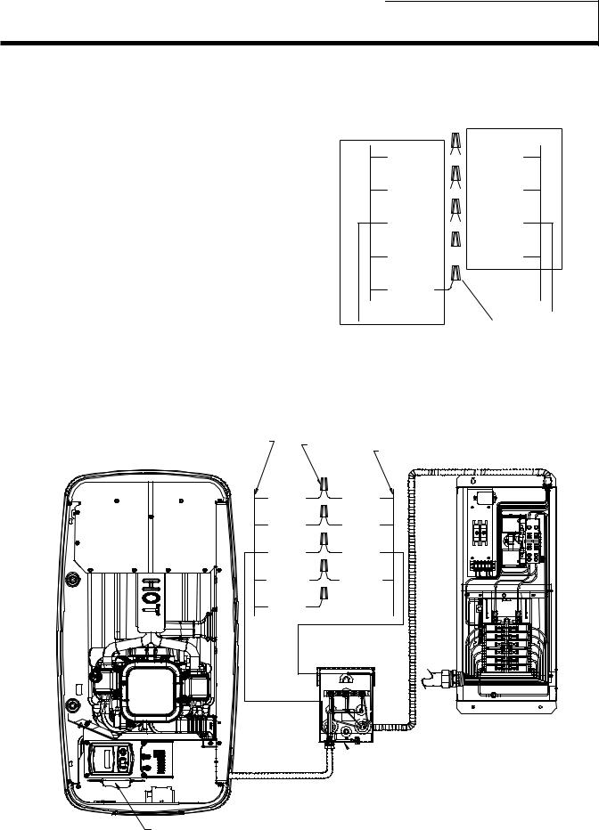
On the current model air-cooled generators Wire 194 was changed to 15B. Wire 15B is still utilized for positive voltage for the transfer relay and Wire 23 is still the control ground for transferring the generator. By following the procedures below it is possible to connect new product with Wire 15B to old or current product that still utilize Wire 194, such as an RTS switch.
Connect a pre-2008 load center switch to a Current or Future air-cooled generator.
Procedure:
1.Follow all instructions located in the Installation Manual that was supplied with the unit regarding mounting of the switch, junction box, and generator.
Note: When installing a standalone 5500 series generator, the battery charger will be located in the generator on the side of the control assembly.
2.Inside the Junction box between the generator and the transfer switch there will be 5 wires coming from the generator and 4 wires from the transfer switch.
“08” & LATER HSB AIR-COOLED GENERATORS
SINGLE & V-TWIN ENGINES
CONTROL WIRES FROM ENGINE GENERATOR
3.Using the following diagram and UL approved wire nuts connect the following wires together. Wire 0 will not be utilized for this setup.
CONTROL WIRES FROM
TRANSFER SWITCH
N1 (YEL) 
 N1 (BLU)
N2 (YEL) 
 N2 (YEL)
23 (WHT) 
 23 (BRN)
15B (RED) 


 194 (ORG)
0 (BLK) |
|
CONTROL WIRES FROM |
WIRE NUTS |
|
|
ENGINE GENERATOR |
|
Figure 1. Wire Connections
|
|
|
|
|
|
|
|
|
PRE “08” LOAD CENTER |
||||||||||||||||||||||||||||||||||||||
|
|
|
|
|
|
|
|
|
|
|
|
TRANSFER SWITCH |
|||||||||||||||||||||||||||||||||||
WIRE |
|
|
|
|
|
|
|
|
|
|
|
|
|
|
|
|
|
|
|
|
|
|
|
|
|
|
|
|
|
|
|
|
|
|
|
|
|
|
|
|
|
|
|
|
|
||
NUTS |
CONTROL WIRES FROM TRANSFER SWITCH |
||||||||||||||||||||||||||||||||||||||||||||||
|
|
|
|
|
|
|
|
|
|
|
|
|
|
|
|
|
|
|
|
|
|
|
|
|
|
|
|
|
|
|
|
|
|
|
|
|
|
|
|
|
|
|
|
|
|
|
|
|
|
|
|
|
|
|
|
|
|
|
|
|
|
|
|
|
|
|
|
|
|
|
|
|
|
|
|
|
|
|
|
|
|
|
|
|
|
|
|
|
|
|
|
|
|
|
|
|
|
|
|
|
|
|
|
|
|
|
|
|
|
|
|
|
|
|
|
|
|
|
|
|
|
|
|
|
|
|
|
|
|
|
|
|
|
|
|
|
|
|
|
|
|
|
|
|
|
|
|
|
|
|
|
|
|
|
|
|
|
|
|
|
|
|
|
|
|
|
|
|
|
|
|
|
|
|
|
|
|
|
|
|
|
|
|
|
|
|
|
|
|
|
|
|
|
|
|
|
|
|
|
|
|
|
|
|
|
|
|
|
|
|
|
|
|
|
|
|
|
|
|
|
|
|
|
|
|
|
|
|
|
|
|
|
|
|
|
|
|
|
|
N1 (YEL) |
N2 (YEL) |
23 (WHT) |
15B (RED) |
0 (BLK) |
N1 |
(BLU) |
N2 |
(YEL) |
23 (BRN) |
|
194 |
(ORG) |
 EXTERNAL CUSTOMER
CONNECTION BOX
INSTALL BATTERY CHARGER GENERAC P/N 0G8023
Figure 2. Post 2008 HSB Interconnections
Page 14
General information |
Part 1 |
Section 1.3 |
|
Non-Prepackaged Interconnections |
|||
|
|
||
|
|
|
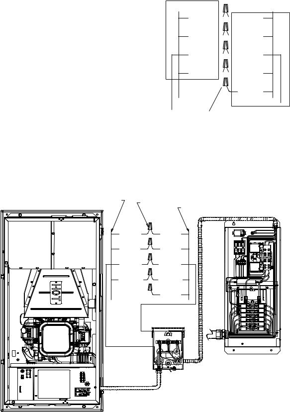
Connect a 2008 and later load center switch to a Pre-2008 air-cooled generator.
Procedure:
1.Follow all instructions located in the Installation Manual that was supplied with the unit regarding mounting of the switch, junction box, and generator.
Note: When installing a standalone pre-2008 generator, the battery charger will be located in the generator utilizing the 12 VDC trickle charger.
2.Inside the Junction box between the generator and the transfer switch there will be 4 wires coming from the generator and 5 wires from the transfer switch.
3.Using the following diagram and UL approved wire nuts connect the following wires together. Wire 0 will not be utilized for this setup.
Note: Remove the battery charger from the transfer switch; it will not be utilized in the operation of the generator.
PRE “08” HSB AIR-COOLED GENERATORS
SINGLE & V-TWIN ENGINES
CONTROL WIRES FROM ENGINE GENERATOR
CONTROL WIRES FROM
ENGINE GENERATOR
N1 (BLU) 
 N1 (YEL)
N2 (YEL) 
 N2 (YEL)
23 (BRN) 
 23 (WHT)
194 (ORG) 
 15B (RED)
|
0 (BLK) |
|
WIRE NUTS |
CONTROL WIRES FROM |
|
TRANSFER SWITCH |
||
|
Figure 3. Wire Connections
|
“08” & LATER LOAD CENTER |
|||||||||||||||||||||||||||||||||||||||||
|
|
|
|
|
|
TRANSFER SWITCH |
||||||||||||||||||||||||||||||||||||
WIRE |
|
|
|
|
|
|
|
|
|
|
|
|
|
|
|
|
|
|
|
|
|
|
|
|
|
|
|
|
|
|
|
|
|
|
|
|
|
|
|
|
|
|
NUTS |
CONTROL WIRES FROM TRANSFER SWITCH |
|||||||||||||||||||||||||||||||||||||||||
|
||||||||||||||||||||||||||||||||||||||||||
|
|
|
|
|
|
|
|
|
|
|
|
|
|
|
|
|
|
|
|
|
|
|
|
|
|
|
|
|
|
|
|
|
|
|
|
|
|
|
|
|
|
|
|
|
|
|
|
|
|
|
|
|
|
|
|
|
|
|
|
|
|
|
|
|
|
|
|
|
|
|
|
|
|
|
|
|
|
|
|
|
|
|
|
|
|
|
|
|
|
|
|
|
|
|
|
|
|
|
|
|
|
|
|
|
|
|
|
|
|
|
|
|
|
|
|
|
|
|
|
|
|
|
|
|
|
|
|
|
|
|
|
|
|
|
|
|
|
|
|
|
|
|
|
|
|
|
|
|
|
|
|
|
|
|
|
|
|
|
|
|
|
|
|
|
|
|
|
|
|
|
|
N1 |
(BLU) |
N1 (YEL) |
N2 |
(YEL) |
N2 (YEL) |
23 (BRN) |
23 (WHT) |
|
194 |
(ORG) |
15B (RED) |
|
|
0 (BLK) |
 EXTERNAL CUSTOMER
CONNECTION BOX
Figure 4. Pre-2008 HSB Interconnections
Page 15

Section 1.4 |
Part 1 |
|
Preparation Before Use |
||
|
||
|
|
General information
General
The installer must ensure that the home standby generator has been properly installed. The system must be inspected carefully following installation. All applicable codes, standards and regulations pertaining to such installations must be strictly complied with. In addition, regulations established by the Occupational Safety and Health Administration (OSHA) must be complied with.
Prior to initial startup of the unit, the installer must ensure that the engine-generator has been properly prepared for use. This includes the following:
•An adequate supply of the correct fuel must be available for generator operation.
•The engine must be properly serviced with the recommended oil.
Fuel Requirements
With LP gas, use only the vapor withdrawal system. This type of system uses the vapors formed above the liquid fuel in the storage tank.
The engine has been fitted with a fuel carburetion system that meets the specifications of the 1997 California Air Resources Board for tamper-proof dual fuel systems. The unit will run on natural gas or LP gas, but it has been factory set to run on natural gas. Should the primary fuel need to be changed to LP gas, the fuel system needs to be reconfigured. See the Reconfiguring the Fuel System section for instructions on reconfiguration of the fuel system.
Recommended fuels should have a Btu content of at least 1,000 Btus per cubic foot for natural gas; or at least 2,520 Btus per cubic foot for LP gas. Ask the fuel supplier for the Btu content of the fuel.
Required fuel pressure for natural gas is 5 inches to 7 inches water column (0.18 to 0.25 psi); and for liquid propane, 10 inches to 12 inches of water column (0.36 to 0.43 psi).
NOTE: All pipe sizing, construction and layout must comply with NFPA 54 for natural gas applications and NFPA 58 for liquid propane applications. Once the generator is installed, verify that the fuel pressure NEVER drops below four (4) inches water column for natural gas or 10 inches water column for liquid propane.
Prior to installation of the generator, the installer should consult local fuel suppliers or the fire marshal to check codes and regulations for proper installation. Local codes will mandate correct routing of gaseous fuel line piping around gardens, shrubs and other landscaping to prevent any damage.
Special considerations should be given when installing the unit where local conditions include flooding, tornados, hurricanes, earthquakes and unstable ground for the flexibility and strength of piping and their connections.
Use an approved pipe sealant or joint compound on all threaded fitting.
All installed gaseous fuel piping must be purged and leak tested prior to initial start-up in accordance with local codes, standards and regulations.
Fuel Consumption
The fuel consumption rates are listed in the SPECIFICATIONS section at the front of this manual.
btu flow requirements - natural gas:
BTU flow required for each unit based on 1000 BTU per cubic foot.
7 kW - 140,000 BTU/Hour
9 kW - 156,000 BTU/Hour
12 kW - 215,000 BTU/Hour
13 kW - 220,000 BTU/Hour
16 kW - 261,000 BTU/Hour
18 kW - 294,000 BTU/Hour

 DANGER
$Gaseous fuels such as natural gas and liquid propane (LP) gas are highly explosive. Even the slightest spark can ignite such fuels and cause an explosion. No leakage of fuel is permitted. Natural gas, which is lighter than air, tends to collect in high areas. LP gas is heavier than air and tends to settle in low areas.
NOTE: A minimum of one approved manual shutoff valve must be installed in the gaseous fuel supply line. The valve must be easily accessible. Local codes determine the proper location.
Reconfiguring The Fuel System
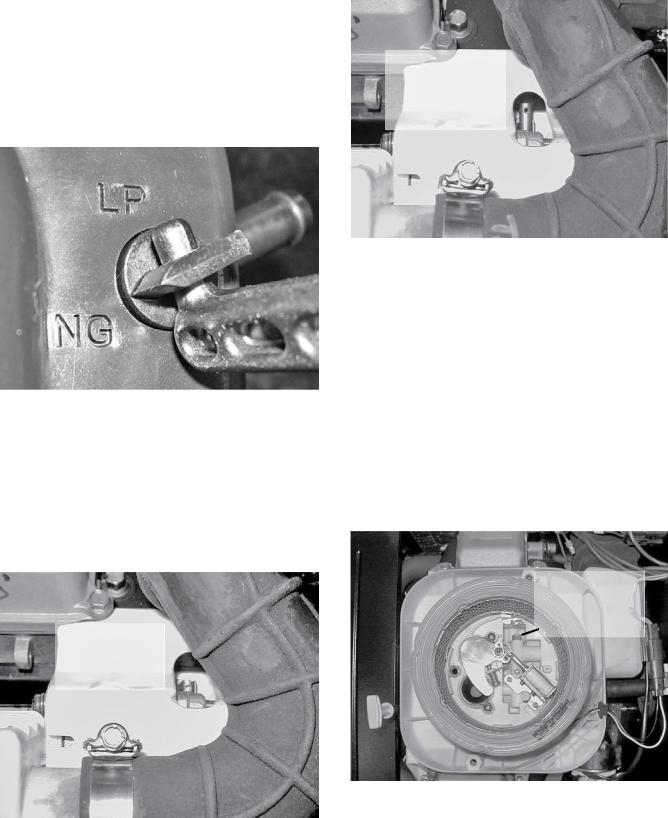
8 kW, 410cc Engine:
To reconfigure the fuel system from NG to LP, follow these steps (Figure 1):
NOTE: The primary regulator for the propane supply is NOT INCLUDED with the generator. A fuel pressure of 10 to 12 inches of water column (0.36 to 0.43 psi) to the fuel inlet of the generator must be supplied.
1.Turn off the main gas supply (if connected).
2.Open the roof and remove the door.
3.Remove the battery (if installed).
4.Locate the plastic T-handle fuel selector in the poly bag supplied with the generator.
5.Locate the selector knob on the air box cover, behind the yellow air filter door and power bulge. The unit comes from the factory in the NG (Natural Gas) position. Grasping the T-handle, insert the pin end into the hole
Page 16
General information |
Part 1 |
Section 1.4 |
|
Preparation before use |
|||
|
|
||
|
|
|
in the selector knob and pull out to overcome spring pressure and then twist clockwise 90 degrees and allow the selector to return in once aligned with the LP (Liquid Propane) position.
6.Save this tool with the Owner's Manual.
7.Install the battery, door and close the roof.
8.Reverse the procedure to convert back to natural gas.
Figure 1. Demand Regulator
10, 12, 14, 16, 17 And 20 kW, V-twin Engines:
To reconfigure the fuel system from NG to LP, follow these steps:
NOTE: The primary regulator for the propane supply is NOT INCLUDED with the generator. A fuel pressure of 10 to 12 inches of water column (0.36 to 0.43 psi) to the fuel inlet of the generator MUST BE SUPPLIED.
FUEL SELECTION
LEVER -
“IN” POSITION FOR NATURAL GAS 
Figure 2. 10 kW, GT-530 (Inlet Hose Slid Back)
FUEL SELECTION LEVER -
“OUT” POSITION FOR LIQUID PROPANE  (VAPOR) FUEL
Figure 3. 10 kW, GT-530 (Inlet Hose Slid Back)
1.Open the roof.
2.For 10 kW units: Loosen clamp and slide back the air inlet hose.
•Slide fuel selector on carburetor out towards the back of the enclosure (Figures 2 and 3).
•Return the inlet hose and tighten clamp securely.
For 12, 14, 16, 17 and 20 kW units: remove the air cleaner cover.
•Slide the selector lever out towards the back of the enclosure (Figures 4 and 5).
•Return the air cleaner cover and tighten the two thumb screws.
3.Close the roof.
4.Reverse the procedure to convert back to natural gas.
FUEL SELECTION
LEVER -
“IN” POSITION FOR NATURAL GAS
Figure 4. 12/14/16/17/20 kW, GT-990/GT-999 (Airbox Cover Removed)
Page 17
Section 1.4 |
Part 1 |
|
Preparation before use |
||
|
||
|
|
General information
FUEL SELECTION LEVER -
“OUT” POSITION FOR
LIQUID PROPANE  (VAPOR) FUEL
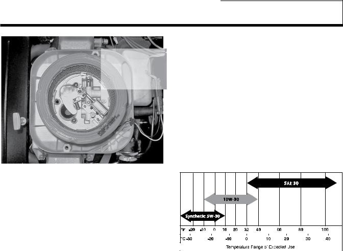
Engine Oil Recommendations
All oil should meet minimum American Petroleum Institute (API) Service Class SJ, SL or better. Use no special additives. Select the oil's viscosity grade according to the expected operating temperature.
•SAE 30 è Above 32° F
•10W-30 è Between 40° F and -10° F
•Synthetic 5W-30 è 10° F and below
Engine crankcase oil capacities for the engines covered in this manual can be found in the specifications section at the beginning of the book.
before it has been properly serviced with the recommended oil may result in an engine failure.Any attempt to crank or start the engine
Figure 5. 12/14/16/17/20 kW, GT-990/GT-999 (Airbox Cover Removed)
SAE 30 |
10W-30 |
Synthetic 5W-30 |
Page 18
General information |
Part 1 |
Section 1.5 |
|
Testing, Cleaning And Drying |
|||
|
|
||
|
|
|
Meters
Devices used to measure electrical properties are called meters. Meters are available that allow one to measure (a) AC voltage, (b) DC voltage, (c) AC frequency, and (d) resistance In ohms. The following apply:
•To measure AC voltage, use an AC voltmeter.
•To measure DC voltage, use a DC voltmeter.
•Use a frequency meter to measure AC frequency In
“Hertz” or “cycles per second”.
•Use an ohmmeter to read circuit resistance, in “ohms”.
The Vom
A meter that will permit both voltage and resistance to be read is the “volt-ohm-milliammeter” or “VOM”.
Some VOMs are of the “analog” type (not shown). These meters display the value being measured by physically deflecting a needle across a graduated scale. The scale used must be Interpreted by the user.
“Digital” VOM’s (Figure 1) are also available and are generally very accurate. Digital meters display the measured values directly by converting the values to numbers.
NOTE: Standard AC voltmeters react to the AVERAGE value of alternating current. When working with AC, the effective value is used. For that reason a different scale is used on an AC voltmeter. The scale is marked with the effective or “rms” value even though the meter actually reacts to the average value. That is why the AC voltmeter will give an Incorrect reading if used to measure direct current (DC).
Figure 1. Digital VOM
Measuring AC Voltage
An accurate AC voltmeter or a VOM may be used to read the generator’s AC output voltage. The following apply:
1.Always read the generator’s AC output voltage only at the unit’s rated operating speed and AC frequency.
2.The generator’s Voltage Regulator can be adjusted for correct output voltage only while the unit is operating at its correct rated speed and frequency.
3.Only an AC voltmeter may be used to measure AC voltage. DO NOT USE A DC VOLTMETER FOR THIS PURPOSE.
*DANGER!: GENERATORS PRODUCE HIGH AND DANGEROUS VOLTAGES. CONTACT WITH HIGH VOLTAGE TERMINALS WILL RESULT IN DANGEROUS AND POSSIBLY LETHAL ELECTRICAL SHOCK.
Measuring DC Voltage
A DC voltmeter or a VOM may be used to measure DC voltages. Always observe the following rules:
1.Always observe correct DC polarity.
a.Some VOM’s may be equipped with a polarity switch.
b.On meters that do not have a polarity switch, DC polarity must be reversed by reversing the test leads.
2.Before reading a DC voltage, always set the meter to a higher voltage scale than the anticipated reading. If in doubt, start at the highest scale and adjust the scale downward until correct readings are obtained.
3.The design of some meters is based on the “current flow” theory while others are based on the “electron flow” theory.
a.The “current flow” theory assumes that direct current flows from the positive (+) to the negative (-).
b.The “electron flow” theory assumes that current flows from negative (-) to positive (+).
NOTE: When testing generators, the “current flow” theory is applied. That is, current is assumed to flow from positive (+) to negative (-).
Measuring AC Frequency
The generator’s AC output frequency is proportional to Rotor speed. Generators equipped with a 2-pole Rotor must operate at 3600 rpm to supply a frequency of 60 Hertz. Units with 4-pole Rotor must run at 1800 rpm to deliver 60 Hertz.
Page 19
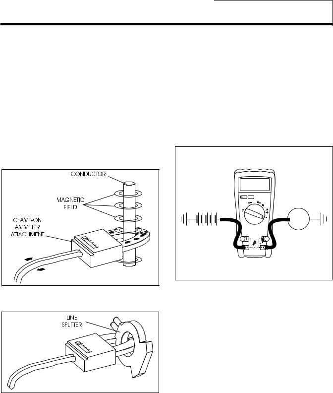
Section 1.5 |
Part 1 |
|
Testing, cleaning and drying |
||
|
||
|
|
General information
Measuring Current
Clamp-On:
To read the current flow, in AMPERES, a clamp-on ammeter may be used. This type of meter indicates current flow through a conductor by measuring the strength of the magnetic field around that conductor. The meter consists essentially of a current transformer with a split core and a rectifier type instrument connected to the secondary. The primary of the current transformer is the conductor through which the current to be measured flows. The split core allows the Instrument to be clamped around the conductor without disconnecting it.
Current flowing through a conductor may be measured safely and easily. A line-splitter can be used to measure current in a cord without separating the conductors.
In-Line:
Alternatively, to read the current flow in AMPERES, an in-line ammeter may be used. Most Digital Volt Ohm Meters (VOM) will have the capability to measure amperes.
This usually requires the positive meter test lead to be connected to the correct amperes plug, and the meter to be set to the amperes position. Once the meter is properly set up to measure amperes the circuit being measured must be physically broken. The meter will be in-line or in series with the component being measured.
In Figure 4 the control wire to a relay has been removed. The meter is used to connect and supply voltage to the relay to energize it and measure the amperes going to it.
1.00 A
BATTERY |
|
|
- |
+ |
RELAY |
|
|
Figure 4. A VOM as an In-line meter
Figure 2. Clamp-On Ammeter
Figure 3. A Line-Splitter
NOTE: If the physical size of the conductor or ammeter capacity does not permit all lines to be measured simultaneously, measure current flow in each individual line. Then, add the Individual readings.
Measuring Resistance
The volt-ohm-milliammeter may be used to measure the resistance in a circuit. Resistance values can be very valuable when testing coils or windings, such as the Stator and Rotor windings.
When testing Stator windings, keep in mind that the resistance of these windings is very low. Some meters are not capable of reading such a low resistance and will simply read CONTINUITY.
If proper procedures are used, the following conditions can be detected using a VOM:
•A “short-to-ground” condition in any Stator or Rotor winding.
•Shorting together of any two parallel Stator windings.
•Shorting together of any two isolated Stator windings.
•An open condition in any Stator or Rotor winding.
Page 20
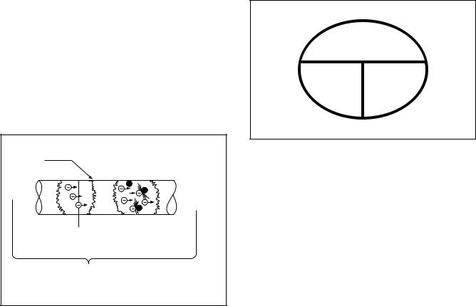
General information |
Part 1 |
Section 1.5 |
|
Testing, cleaning and drying |
|||
|
|
||
|
|
|
Component testing may require a specific resistance value or a test for INFINITY or CONTINUITY. Infinity is an OPEN condition between two electrical points, which would read as no resistance on a VOM. Continuity is a closed condition between two electrical points, which would be indicated as very low resistance or “ZERO” on a VOM.
Electrical Units
Ampere:
The rate of electron flow in a circuit is represented by the AMPERE. The ampere is the number of electrons flowing past a given point at a given time. One AMPERE is equal to just slightly more than six thousand million billion electrons per second.
With alternating current (AC), the electrons flow first in one direction, then reverse and move in the opposite direction. They will repeat this cycle at regular intervals. A wave diagram, called a “sine wave” shows that current goes from zero to maximum positive value, then reverses and goes from zero to maximum negative value. Two reversals of current flow is called a cycle. The number of cycles per second is called frequency and is usually stated in “Hertz”.
Volt:
The VOLT is the unit used to measure electrical PRESSURE, or the difference in electrical potential that causes electrons to flow. Very few electrons will flow when voltage is weak. More electrons will flow as voltage becomes stronger. VOLTAGE may be considered to be a state of unbalance and current flow as an attempt to regain balance. One volt is the amount of EMF that will cause a current of 1 ampere to flow through 1 ohm of resistance.
Conductor of a Circuit
- 
oHm - Unit measuring resistance or opposition to+flow
amPErE - Unit measuring rate of
current flow (number of electrons past a given point)
Volt - Unit measuring force or difference in potential causing current flow
Figure 5. Electrical Units
Ohm:
The OHM is the unit of RESISTANCE. In every circuit there is a natural resistance or opposition to the flow of electrons. When an EMF is applied to a complete circuit, the electrons are forced to flow in a single direction rather than their free or orbiting pattern. The resistance of a conductor depends on (a) its physical makeup, (b) its cross-sectional area, (c) its length, and (d) its temperature. As the conductor’s temperature increases, its resistance increases in direct proportion. One (1) ohm of resistance will permit one (1) ampere of current to flow when one (1) volt of electromotive force (EMF) is applied.
Ohm’s Law
A definite and exact relationship exists between VOLTS, OHMS and AMPERES. The value of one can be calculated when the value of the other two are known. Ohm’s Law states that in any circuit the current will increase when voltage increases but resistance remains the same, and current will decrease when resistance Increases and voltage remains the same.
VOLTS
(E)
AMPS OHMS
(I)(R)
Figure 6. Ohm’s Law
If AMPERES is unknown while VOLTS and OHMS are known, use the following formula:
AMPERES = VOLTSohmS
If VOLTS is unknown while AMPERES and OHMS are known, use the following formula:
VOLTS = AMPERES x OHMS
If OHMS is unknown but VOLTS and AMPERES are known, use the following:
OHMS = |
VOLTS |
|
AMPERES |
||
|
Page 21
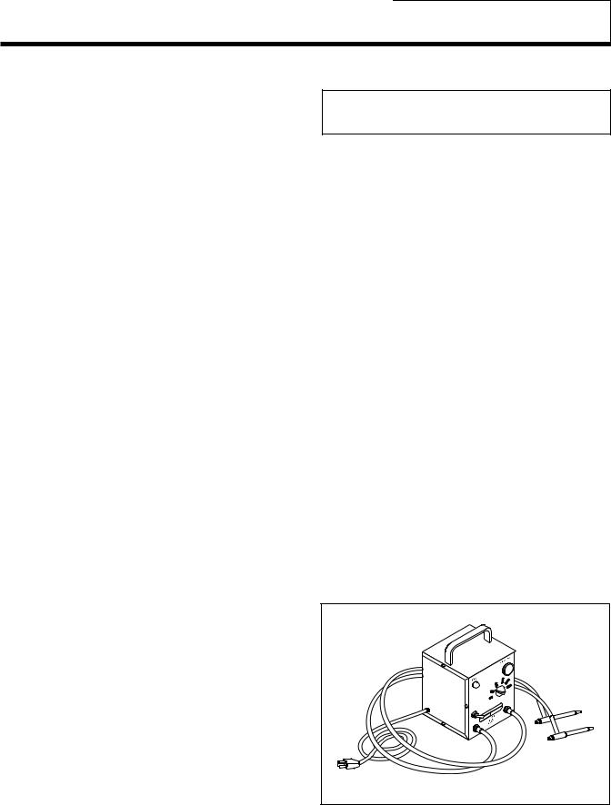
Section 1.5 |
Part 1 |
|
Testing, cleaning and drying |
||
|
||
|
|
General information
Visual Inspection
When it becomes necessary to test or troubleshoot a generator, it is a good practice to complete a thorough visual inspection. Remove the access covers and look closely for any obvious problems. Look for the following:
•Burned or broken wires, broken wire connectors, damaged mounting brackets, etc.
•Loose or frayed wiring insulation, loose or dirty connections.
•Check that all wiring is well clear of rotating parts.
•Verify that the Generator properly connected for the correct rated voltage. This is especially important on new installations. See Section 1.2, “AC Connection Systems”.
•Look for foreign objects, loose nuts, bolts and other fasteners.
•Clean the area around the Generator. Clear away paper, leaves, snow, and other objects that might blow against the generator and obstruct its air openings.
Insulation Resistance
The insulation resistance of stator and rotor windings is a measurement of the integrity of the insulating materials that separate the electrical windings from the generator steel core. This resistance can degrade over time or due to such contaminants as dust, dirt, oil, grease and especially moisture. In most cases, failures of stator and rotor windings is due to a breakdown in the insulation. And, in many cases, a low insulation resistance is caused by moisture that collects while the generator is shut down. When problems are caused by moisture buildup on the windings, they can usually be corrected by drying the windings. Cleaning and drying the windings can usually eliminate dirt and moisture built up in the generator windings.
The Megohmmeter
General:
The MINIMUM acceptable megger reading for stators may be calculated using the following formula:
MINIMUM INSULATION |
|
GENERATOR RATED VOLTS |
|
|
RESISTANCE |
= |
__________________________ |
+1 |
|
1000 |
||||
(in “Megohms”) |
|
|
||
|
|
|
EXAMPLE: Generator is rated at 120 volts AC. Divide “120” by “1000” to obtain “0.12”. Then add “1” to obtain “1.12” megohms. Minimum Insulation resistance for a 120 VAC stator is 1.12 megohms.
If the stator insulation resistance is less than the calculated minimum resistance, clean and dry the stator. Then, repeat the test. If resistance is still low, replace the stator.
Use the Megger to test for shorts between isolated windings as outlined “Stator Insulation Tests”.
Also test between parallel windings. See “Test Between Windings” on next page.
Testing Rotor Insulation (12-20kW):
Apply a voltage of 500 volts across the rotor positive (+) slip ring (nearest the rotor bearing), and a clean frame ground (i.e. the rotor shaft). DO NOT EXCEED 500 VOLTS AND DO NOT APPLY VOLTAGE LONGER THAN 1 SECOND. FOLLOW THE MEGGER MANUFACTURER’S INSTRUCTIONS CAREFULLY.
ROTOR MINIMUM INSULATION RESISTANCE: 1.5 megohms
Testing Rotor Insulation (8-10kW):
No test available.
*CAUTION: Before attempting to measure insulation resistance, first disconnect and isolate all leads of the winding to be tested. Electronic components, diodes, surge protectors, relays, voltage regulators, etc., can be destroyed if subjected to high megger voltages.
A megohmmeter, often called a “megger”, consists of |
|
a meter calibrated in megohms and a power supply. |
|
Use a power supply of 500 volts when testing stators |
|
or rotors. DO NOT APPLY VOLTAGE LONGER THAN |
|
ONE (1) SECOND. |
|
Testing Stator Insulation: |
|
All parts that might be damaged by the high meg- |
|
ger voltages must be disconnected before testing. |
|
Isolate all stator leads (Figure 8) and connect all of |
|
the stator leads together. FOLLOW THE MEGGER |
|
MANUFACTURER’S INSTRUCTIONS CAREFULLY. |
|
Use a megger power setting of 500 volts. Connect |
|
one megger test lead to the junction of all stator |
|
leads, the other test lead to frame ground on the sta- |
|
tor can. Read the number of megohms on the meter. |
Figure 7. One Type of Hi-Pot Tester |
Page 22
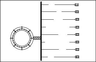
General information |
Part 1 |
Section 1.5 |
|
Testing, cleaning and drying |
|||
|
|
||
|
|
|
Hi-pot Tester:
A “Hi-Pot” tester is shown in Figure 7. The model shown is only one of many that are commercially available. The tester shown is equipped with a voltage selector switch that permits the power supply voltage to be selected. It also mounts a breakdown lamp that will illuminate to indicate an insulation breakdown during the test.
Stator Insulation Resistance Test
(12-20 kW)
General:
Units with air-cooled engine are equipped with (a) dual stator AC power windings, and (b) excitation or DPE winding. Insulation tests of the stator consist of
(a) testing all windings to ground, (b) testing between isolated windings, and (c) testing between parallel windings. Figure 8 is a pictorial representation of the various stator leads on units with air-cooled engines.
Testing All Stator Windings To Ground:
1.Disconnect stator output leads 11 and 44 from the generator main line circuit breaker.
2.Remove stator output leads 22 and 33 from the neutral connection and separate the two leads.
3.Disconnect Wires 11 and 22 from Voltage Regulator. Ensure these wires are not touching any other components on the generator.
2 |
|
|
6 |
|
11P |
11S |
(12-20 kW) |
|
22P |
22S |
(12-20 kW) |
|
33 |
44 |
|
Figure 8. Stator Winding Leads
4.Connect the terminal ends of Wires 11, 22, 33 and 44 together. Make sure the wire ends are not touching any part of the generator frame or any terminal.
5.Connect the red test probe of the Hi-Pot tester to the joined terminal ends of stator leads 11, 22, 33 and 44. Connect the black tester lead to a clean frame ground on the stator can. With tester leads connected in this manner, proceed as follows:
a.Turn the Hi-Pot tester switch OFF.
b.Plug the tester cord into a 120 volt AC wall socket and set its voltage selector switch to “1500 volts”.
c.Turn the tester switch ON and observe the breakdown lamp on tester. DO NOT APPLY VOLTAGE LONGER THAN 1 SECOND. After one (1) second, turn the tester switch OFF.
If the breakdown lamp comes on during the one-sec- ond test, the stator should be cleaned and dried. After cleaning and drying, repeat the insulation test. If, after cleaning and drying, the stator fails the second test, the stator assembly should be replaced.
6.Proceed to the Voltage Regulator. Each winding will be individually tested for a short to ground. Refer to Steps 5a-5c and perform the same test on the following wires:
Wire |
Winding |
Number |
|
22S |
Sense Lead Power |
|
|
11S |
Sense Lead Power |
|
|
6 |
Excitation |
|
|
2 |
Excitation |
|
|
0 |
Ground |
|
|
4 |
Positive to Brush Ground |
|
|
Test Between Windings:
1.Disconnect Stator Output Leads 11 and 44 from the generator main line circuit breaker.
2.Remove Stator Output Leads 22 and 33 from the neutral connection and separate the two leads.
3.Disconnect Wires 11, 22, 2, and 6 from Voltage Regulator. Ensure these wires are not touching any other components on the generator.
4.Connect the red tester probe to Wire 2. Connect the black tester probe to Stator Lead 11. Refer to Steps 5a through 5c of “TESTING ALL STATOR WINDINGS TO GROUND” on previous page.
5.Repeat Step 4 between Wire 2 and Stator Lead 33.
6.Repeat Step 4 between Stator Lead 11 and Stator Lead 33.
Stator Insulation Resistance Test
(8-10 kW)
General:
Units with air-cooled engine are equipped with (a) dual stator AC power windings, and (b) excitation or DPE winding. Insulation tests of the stator consist of
(a) testing all windings to ground, (b) testing between isolated windings, and (c) testing between parallel windings. Figure 8 is a pictorial representation of the various stator leads on units with air-cooled engines.
Page 23
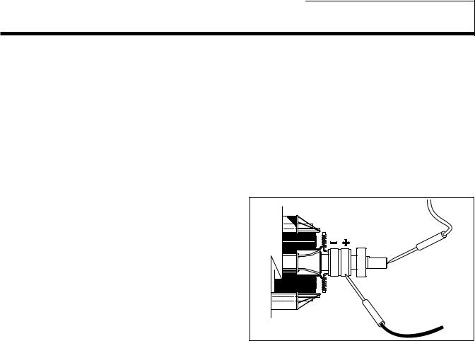
Section 1.5 |
Part 1 |
|
Testing, cleaning and drying |
||
|
||
|
|
General information
Testing All Stator Windings To Ground:
1.Disconnect Stator Output Leads 11 and 44 from the generator main line circuit breaker.
2.Disconnect Stator Output Leads 2 and 6 from the capacitor located on the end of the stator assembly.
3.Remove Stator Output Leads 22 and 33 from the neutral connection and separate the two leads.
4.Connect the terminal ends of Wires 11, 22, 33, and 44 together. Make sure the wire ends are not touching any part of the generator frame or any terminal.
5.Connect the red test probe of the Hi-Pot tester to the joined terminal ends of Stator Leads 11, 22, 33, and 44. Connect the black tester lead to a clean frame ground on the stator can. With tester leads connected in this manner, proceed as follows:
a.Turn the Hi-Pot tester switch OFF.
b.Plug the tester cord into a 120 volt AC wall socket and set its voltage selector switch to “1500 volts”.
c.Turn the tester switch ON and observe the breakdown lamp on tester. DO NOT APPLY VOLTAGE LONGER THAN 1 SECOND. After one (1) second, turn the tester switch OFF.
6.Connect the terminal ends of Wires 2 and 6 together. Make sure the wire ends are not touching any part of the generator frame or any terminal.
7.Repeat Step 5.
If the breakdown lamp came on during the one (1) second test, cleaning and drying of the rotor may be necessary. After cleaning and drying, repeat the insulation breakdown test. If breakdown lamp comes on during the second test, replace the rotor assembly.
Rotor Insulation Resistance Test (8-10 kW)
No test available.
Rotor Insulation Resistance Test (12-20 kW)
Before attempting to test rotor insulation, the brush holder must be completely removed. The rotor must be completely isolated from other components before starting the test. Attach all leads of all stator windings to ground.
1.Connect the red tester lead to the positive (+) slip ring (nearest the rotor bearing).
2.Connect the black tester probe to a clean frame ground, such as a clean metal part of the rotor shaft.
3.Turn the tester switch OFF.
4.Plug the tester into a 120 volts AC wall socket and set the voltage switch to “1500 volts”.
5.Turn the tester switch “On” and make sure the pilot light has turned on.
6.Observe the breakdown lamp, then turn the tester switch OFF. DO NOT APPLY VOLTAGE LONGER THAN ONE
(1) SECOND.
If the breakdown lamp came on during the one (1) second test, cleaning and drying of the rotor may be necessary. After cleaning and drying, repeat the insulation breakdown test. If breakdown lamp comes on during the second test, replace the rotor assembly.
POSITIVE (+) |
TEST LEAD |
Figure 9. Testing Rotor Insulation (12-20kW)
Cleaning The Generator
Caked or greasy dirt may be loosened with a soft brush or a damp cloth. A vacuum system may be used to clean up loosened dirt. Dust and dirt may also be removed using dry, low-pressure air (25 psi maximum).
*CAUTION: Do not use sprayed water to clean the generator. Some of the water will be retained on generator windings and terminals, and may cause very serious problems.
Drying The Generator
To dry a generator, proceed as follows:
1.Open the generator main circuit breaker. NO ELECTRICAL LOADS MUST BE APPLIED TO THE GENERATOR WHILE DRYING.
2.Disconnect all Wires 6 from the voltage regulator.
3.Provide an external source to blow warm, dry air through the generator interior (around the rotor and stator windings. DO NOT EXCEED 185° F. (85° C.).
4.Start the generator and let it run for 2 or 3 hours.
5.Shut the generator down and repeat the stator and rotor insulation resistance tests.
Page 24
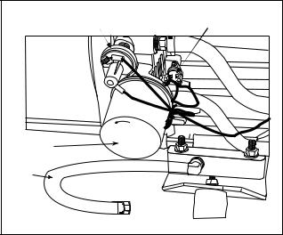
General information |
Part 1 |
Section 1.6 |
|
Engine-generator Protective Devices |
|||
|
|
||
|
|
|
General
Standby electric power generators will often run unattended for long periods of time. Such operating parameters as (a) battery voltage, (b) engine oil pressure, (c) engine temperature, (d) engine operating speed, and (e) engine cranking and startup are not monitored by an operator during automatic operation. Because engine operation will not be monitored, the use of engine protective safety devices is required to prevent engine damage in the event of a problem.
Generator engines mount several engine protective devices. These devices work in conjunction with a circuit board, to protect the engine against such operating faults as (a) low battery, (b) low engine oil pressure, (c) high temperature, (d) overspeed, and
(e) overcrank. On occurrence of any one or more of those operating faults, circuit board action will effect an engine shutdown.
Low Battery
The microprocessor will continually monitor the battery voltage and turn on the Low Battery Warning if the battery voltage falls below 10.8 volts for one
(1) minute. No other action is taken on a low battery condition. Low battery voltage is a non-latching alarm which will automatically clear if the battery voltage rises above 11.0 volts. Battery voltage is NOT monitored during the crank cycle.
Low Oil Pressure Shutdown
See Figure 1. An oil pressure switch is mounted on the engine oil filter adapter. This switch has normally closed contacts that are held open by engine oil pressure during cranking and startup. Should oil pressure drop below approximately 5 psi, the switch contacts will close. On closure of the switch contacts, a Wire 86 circuit from the circuit board will be connected to ground. Circuit board action will then de-energize a “run relay” (on the circuit board). The run relay’s normally open contacts will then open and a 12 volts DC power supply to a Wire 14 circuit will then be terminated. This will result in closure of a fuel shutoff solenoid and loss of engine ignition.
High Temperature Switch
This switch’s contacts (Figure 1) close if the temperature should exceed approximately 144° C (293° F), initiating an engine shutdown. The generator will automatically restart and the fault on the generator control panel will reset once the temperature has returned to a safe operating level.
Overspeed Shutdown
During engine cranking and operation, the circuit board receives AC voltage and frequency signals from the ignition magneto, via Wire 18. Should the speed exceed approximately 72 Hz (4320 rpm), circuit board action will de-energize a “run relay” (mounted on the circuit board). The relay’s contacts will open, to terminate engine ignition and close a fuel shutoff solenoid. The engine will then shut down. This feature protects the engine-generator against damaging overspeeds.
NOTE: The circuit board also uses rpm sensing to terminate engine cranking.
Rpm Sensor Failure
During cranking, if the board does not see a valid RPM signal within three (3) seconds, it will shut down and latch out on RPM sensor loss.
During running, if the RPM signal is lost for one full second the board will shut down the engine, wait 15 seconds, then re-crank the engine.
•If an RPM signal is not detected within the first three
(3) seconds of cranking, the control board will shut the engine down and latch out on RPM sensor loss.
•If the RPM signal is detected the engine will start and run normally. If the RPM signal is subsequently lost again, the control board will try one more recrank attempt before latching out and flashing the overspeed LED or RPM Sensor Failure.
LOW OIL SWITCH |
HIGH TEMP SWITCH |
|
LO |
|
O |
|
S |
|
E |
|
N |
OIL FILTER |
|
OIL |
|
DRAIN |
|
HOSE |
|
Figure 1. Engine Protective Switches on an Air-Cooled Engine
Page 25

Section 1.6 |
Part 1 |
|
Engine-generator protective devices |
||
|
||
|
|
General information
Overcrank Shutdown
This feature prevents the generator from damaging itself when it continually attempts to start and another problem, such as no fuel supply, prevents it from starting. The unit will crank and rest for a preset time limit. Then, it will stop cranking, and the LCD screen or the LED on the generator control panel will light indicating an overcrank failure. The AUTO-OFF-MANUAL switch will need to be set to OFF and then back to AUTO to reset the generator control board.
NOTE: If the fault is not repaired, the overcrank feature will continue to activate.
The system will control the cyclic cranking as follows: 16 second crank, seven (7) second rest, 16 second crank, seven (7) second rest followed by three (3) additional cycles of seven (7) second cranks followed by seven (7) second rests.
Choke Operation:
1.The 990/999cc engines have an electric choke in the air box that is automatically controlled by the electronic control board.
2.The 530cc engines have an electric choke on the divider panel air inlet hose that is automatically controlled by the electronic control board.
3.The 410cc engines have a choke behind the air box that is automatically controlled by the electronic control board.
Failure to Start:
This is defined as any of the following occurrences during cranking.
1.Not reaching starter dropout within the specified crank cycle. Starter dropout is defined as four (4) cycles at 1,500 RPM (1,800 RPM for 8 kW units).
2.Reaching starter dropout, but then not reaching 2200 RPM within 15 seconds. In this case the control board will go into a rest cycle for seven (7) seconds, then continue the rest of the crank cycle.
During a rest cycle the start and fuel outputs are deenergized and the magneto output is shorted to ground.
Cranking Conditions:
The following notes apply during cranking cycle.
1.Starter motor will not engage within five (5) seconds of the engine shutting down.
2.The fuel output will not be energized with the starter.
3.The starter and magneto outputs will be energized together.
4.Once the starter is energized the control board will begin looking for engine rotation. If it does not see an RPM signal within three (3) seconds it will shut down and latch out on RPM sensor loss.
5.Once the control board sees an RPM signal it will energize the fuel solenoid, drive the throttle open and continue the crank sequence.
6.Starter motor will disengage when speed reaches starter dropout.
7.If the generator does not reach 2200 RPM within 15 seconds, re-crank cycle will occur.
8.If engine stops turning between starter dropout and 2200 RPM, the board will go into a rest cycle for seven (7) seconds then re-crank (if additional crank cycles exist).
9.Once started, the generator will wait for a hold-off period before starting to monitor oil pressure and oil temperature (refer to the Alarm Messages section for hold-off times).
10.During Manual start cranking, if the Mode switch is moved from the Manual position, the cranking stops immediately.
11.During Auto mode cranking, if the Utility returns, the cranking cycle does NOT abort but continues until complete. Once the engine starts, it will run for one (1) minute, then shut down.
Page 26
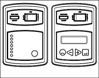
General information |
Part 1 |
Section 1.7 |
|
Operating Instructions |
|||
|
|
||
|
|
|
Control Panel
SYSTEM READY |
|
|
LOW BATTERY |
|
|
LOW OIL PRESSURE |
|
|
HIGH OIL TEMPERATURE |
SET |
|
|
|
|
OVERSPEED |
EXERCISE |
|
RPM SENSOR LOSS |
ECS |
ENTER |
|
|
|
OVERCRANK |
|
|
8 kW UNITS 10-20 kW UNITS
Figure 1. Generator Control Panel
Auto-Off-Manual Switch:
Use this switch to (a) select fully automatic operation,
(b) to crank and start the engine manually, and (c) to shut the unit down or to prevent automatic startup.
1.AUTO position:
a.Select AUTO for fully automatic operation.
b.When AUTO is selected, circuit board will monitor utility power source voltage.
c.Should utility voltage drop below a preset level and remain at such a low level for a preset time, circuit board action will initiate engine cranking and startup.
d.Following engine startup, circuit board action will initiate transfer of electrical loads to the “Standby” source side.
e.On restoration of utility source voltage above a preset level, circuit board action will initiate retransfer back to the “Utility Source” side.
f.Following retransfer, circuit board will shut the engine down and will then continue to monitor utility source voltage.
2.OFF Position:
a.Set the switch to OFF to stop an operating engine.
b.To prevent an automatic startup from occurring, set the switch to OFF.
3.MANUAL Position:
a.Set switch to MANUAL to crank and start unit manually.
b.Engine will crank cyclically and start (same as automatic startup, but without transfer). The unit will transfer if utility voltage is not available.
*DANGER: WHEN THE GENERATOR IS INSTALLED IN CONJUNCTION WITH AN AUTOMATIC TRANSFER SWITCH, ENGINE CRANKING AND STARTUP CAN OCCUR AT ANY TIME WITHOUT WARNING (PROVIDING THE AUTO-OFF-MANUAL SWITCH IS SET TO AUTO). TO PREVENT AUTOMATIC STARTUP AND POSSIBLE INJURY THAT MIGHT BE CAUSED BY SUCH STARTUP, ALWAYS SET THE AUTO-OFF-MANUAL SWITCH TO ITS OFF POSITION BEFORE WORKING ON OR AROUND THIS EQUIPMENT.
7.5 Amp Fuse:
This fuse protects the DC control circuit (including the circuit board) against overload. If the fuse element has melted open due to an overload, engine cranking or running will not be possible. Should fuse replacement become necessary, use only an identical 7.5 amp replacement fuse.
SETTING THE EXERCISE TIMER:
This generator is equipped with an exercise timer. Once it is set, the generator will start and exercise every seven days, on the day of the week and at the time of day specified. During this exercise period, the unit runs for approximately 12 minutes and then shuts down. Transfer of loads to the generator output does not occur during the exercise cycle unless utility power is lost.
8kW:
A switch on the control panel (see Figure1) permits selection of the day and time for the system to exercise. At the chosen time, perform the following sequence to select the desired day and time of day the system will exercise. Remember seasonal time changes affect the exercise settings.
1.Verify that the AUTO-OFF-MANUAL switch is set to AUTO.
2.Press and hold the “Set Exercise” switch for several seconds. All the red LED’s will stop flashing immediately and the generator will start.
3.The generator will start and run for approximately 12 minutes and then shut down. The exerciser is now set to run at this time of day each week.
Example: If the “Set Exercise” pressed on Saturday afternoon at 2:00 p.m., the generator will start and exercise for approximately 12 minutes every Saturday at 2:00 p.m.
NOTE: The exerciser will only work in the AUTO mode and will not work unless this procedure is performed. The exerciser will need to be reset every time the 12 Volt battery is disconnected and then reconnected, and when the fuse is removed and/or replaced.
Page 27

Section 1.7 |
Part 1 |
|
Operating instructions |
||
|
||
|
|
General information
10-20 KW – INSTALLATION ASSISTANT:
Upon first power up of the generator, the display interface will begin an installation assistant. The assistant will prompt the user to set the minimum settings to operate. These settings are simply: Current Date/Time and Exercise Day/Time. The maintenance intervals will be initialized when the exercise time is entered for the first time (Figure 3.2).
The exercise settings can be changed at any time via the "EDIT" menu (see Appendix, "Menu System").
If the 12 Volt battery is disconnected or the fuse removed, the Installation Assistant will operate upon power restoration. The only difference is the display will only prompt the customer for the current Time and Date.
If the installer tests the generator prior to installation, press the “ENTER” key to avoid setting up the exercise time. This will ensure that when the customer powers up the unit, he will still be prompted to enter an exercise time.
NOTE:The exerciser will only work in the AUTO mode and will not work unless this procedure is performed. The current date/time will need to be reset every time the 12 Volt battery is disconnected and then reconnected, and/or when the fuse is removed.
To Select Automatic Operation
The following procedure applies only to those installations in which the air-cooled, automatic standby generator is installed in conjunction with a transfer switch. Transfer switches do not have an intelligence circuit of their own. Automatic operation on transfer switch and generator combinations is controlled by circuit board action.
To select automatic operation when a transfer switch is installed along with a home standby generator, proceed as follows:
1.Check that the transfer switch main contacts are at their UTILITY position, i.e., the load is connected to the power supply. If necessary, manually actuate the switch main contacts to their UTILITY source side. See Part 3 of this manual, as appropriate, for instructions.
2.Check that utility source voltage is available to transfer switch terminal lugs N1 and N2 (2-pole, 1-phase transfer switches).
3.Set the generator AUTO-OFF-MANUAL switch to its AUTO position.
4.Actuate the generator main line circuit breaker to its “On” or “Closed” position. With the preceding Steps 1 through 4 completed, a dropout in utility supply voltage below a preset level will result in automatic generator cranking and start-up. Following startup, the transfer switch will be actuated to its “Standby” source side, i.e., loads powered
by the standby generator.
Manual Transfer To “Standby” and
Manual Startup
To transfer electrical loads to the “Standby” (generator) source and start the generator manually, proceed as follows:
1.On the generator panel, set the AUTO-OFF-MANUAL switch to OFF.
2.On the generator, set the main line circuit breaker to it’s OFF or “Open” position.
3.Turn OFF the power supply to the transfer switch, using whatever means provided (such as a utility source line circuit breaker).
4.Manually actuate the transfer switch main contacts to their “Standby” position, i.e., loads connected to the “Standby” power source side.
NOTE: For instructions on manual operation of transfer switches, see Part 3.
5.On the generator panel, set the AUTO-OFF-MANUAL switch to MANUAL. The engine should crank and start.
6.Let the engine warm up and stabilize for a minute or two at no-load.
7.Set the generator main line circuit breaker to its “On” or “Closed” position. The generator now powers the electrical loads.
Manual Shutdown And Retransfer
Back To “Utility”
To shut the generator down and retransfer electrical loads back to the UTILITY position, proceed as follows:
1.Set the generator main line circuit breaker to its OFF or “Open” position.
2.Let the generator run at no-load for a few minutes, to cool.
3.Set the generator AUTO-OFF-MANUAL switch to OFF. Wait for the engine to come to a complete stop.
4.Turn off the utility power supply to the transfer switch using whatever means provided (such as a utility source main line circuit breaker)
5.Manually actuate the transfer switch to its UTILITY source side, i.e., load connected to the utility source.
6.Turn on the utility power supply to the transfer switch, using whatever means provided.
7.Set the generator AUTO-OFF-MANUAL switch to AUTO.
Page 28
 Loading...