


Owner’s Manual and
Installation Instructions
Air-cooled Recreational
Vehicle Generators
• Model: 004700-0
QUIETPACT 40G
|
GENERAOHVI |
|
|
|
|
|
|
||
G |
A |
|
C |
|
|
|
|
|
|
E |
|
|
|
|
|
|
|
|
|
|
|
POW |
|
|
® |
|
|
|
|
|
C ® |
ERED |
|
|
|
|
|
||
|
r S |
|
|
|
|
|
|
||
|
Po |
|
|
|
|
|
|
|
|
|
we |
yste |
|
|
|
|
|
|
|
|
|
|
|
|
|
|
|
|
|
|
|
ms, Inc - Whitewater,WI |
|
|
|
|
|||
|
GENERA |
|
|
|
|
|
|
||
|
QUIETPACTRV |
|
|
|
|
||||
|
|
|
|
OHVI IN |
|
|
|
|
|
|
|
|
|
|
DUSTR |
|
|
|
|
|
|
|
|
|
|
IAL |
|
|
|
|
|
|
|
|
|
|
ENG |
||
|
|
|
|
|
OR: |
|
|
|
INE |
|
|
|
|
SE |
40G |
||||
|
|
|
|
RVICE |
|
|
|
|
|
|
|
|
|
|
LO |
|
|
|
|
|
|
|
|
|
CAT |
1.8 |
|
|
|
|
|
|
|
|
|
00. |
333. |
|
|
|
|
|
|
|
|
|
1322 |
||
|
|
|
|
|
|
|
|
||
|
|
|
|
|
|
|
|
|
|
This manual should remain with the unit.
INTRODUCTION
Thank you for purchasing this model of the PRIMEPACT product line by Generac Power Systems Inc. This model is designed and manufactured to supply electrical power for recreational vehicles.
READ THIS MANUAL THOROUGHLY
If you do not understand any portion of this manual, contact Generac or your nearest Generac Authorized Service Dealer for starting, operating and servicing procedures.
Throughout this publication, and on tags and decals affixed to the generator, DANGER, WARNING, CAUTION and NOTE blocks are used to alert you to special instruction about a particular operation that may be hazardous if performed incorrectly or carelessly. Observe them carefully. Their definitions are as follows:

 DANGER
After this heading, you can read instructions that, if not strictly complied with, will result in personal injury or property damage.
After this heading, you can read instructions that, if not strictly complied with, may result in personal injury or property damage.
After this heading, you can read instructions that, if not strictly complied with, could result in damage to equipment and/or property.
NOTE:
After this heading, you can read explanatory statements that require special emphasis.
These safety warnings cannot eliminate the hazards that they indicate. Common sense and strict compliance with the special instructions while performing the service are essential to preventing accidents.
Four commonly used safety symbols accompany the DANGER, WARNING and CAUTION blocks. The type of information each indicates follows:
This symbol points out important safety informa- ! tion that, if not followed, could endanger personal
safety and/or property of you and others.
This symbol points out potential explosion hazard. |
 This symbol points out potential fire hazard.
This symbol points out potential electrical shock hazard.
The operator (driver) is responsible for proper and safe use of the vehicle and its equipment, and the safety of all vehicle occupants. We strongly recommend that the operator read this manual and thoroughly understand all instructions before using this equipment. We also strongly recommend instructing other occupants in the vehicle to properly start and operate the generator. This prepares them if they need to operate the equipment in an emergency.
CONTENTS
This manual contains pertinent owner’s information, including warranty, electrical diagrams, exploded views and lists of repair parts for generator model numbers 004700-0. In addition, the latter portion of this manual contains information necessary for the proper installation of these generators.
OPERATION AND MAINTENANCE
It is the operator's responsibility to perform all safety checks, to make sure that all maintenance for safe operation is performed promptly, and to have the equipment checked periodically by a Generac Authorized Service Dealer. Normal maintenance service and replacement of parts are the responsibility of the owner/operator and, as such, are not considered defects in materials or workmanship within the terms of the warranty. Individual operating habits and usage contribute to the need for maintenance service.
Proper maintenance and care of your generator ensure a minimum number of problems and keep operating expenses at a minimum. See your Generac Authorized Service Dealer for service aids and accessories.
HOW TO OBTAIN SERVICE
When your generator requires servicing or repairs, simply contact a Generac Authorized Service Dealer for assistance. Service technicians are factory-trained and are capable of handling all of your service needs.
When contacting a Generac Authorized Service Dealer or the factory about parts and service, always supply the complete model number and serial number of your unit as given on its data decal, which is located on your generator.
Model No. ____________ Serial No. ______________
AUTHORIZED SERVICE
DEALER LOCATION
To locate the GENERAC AUTHORIZED SERVICE
DEALER nearest you, please call this number:
1-800-333-1322
ONLY DEALER LOCATION INFORMATION
CAN BE OBTAINED AT THIS NUMBER.
Generac® Power Systems, Inc.

Table of Contents
QUIETPACT 40G Recreational Vehicle Generator
Part I – Owner’s Manual
Introduction ...................................... |
Inside Front Cover |
|
Read This Manual Thoroughly .................................... |
|
IFC |
Contents ...................................................................... |
|
IFC |
Operation and Maintenance ........................................ |
|
IFC |
How to Obtain Service.................................................. |
|
IFC |
Authorized Service Dealer Locator Number |
....................IFC |
|
Safety Rules |
...................................................................... |
2 |
|
Section 1 – General ..................................Information |
4 |
||
1.1 |
Generator ............................................Identification |
4 |
|
1.2 |
Generator ............................................Applicability |
5 |
|
1.3 |
Safety..... .................................................................. |
|
5 |
1.4 |
Generator ............................AC Connection System |
5 |
|
1.5 |
Specifications .......................................................... |
5 |
|
|
1.5.1 ...................................... |
Fuel Requirements |
5 |
|
1.5.2 ...................................... |
Fuel Consumption |
6 |
|
1.5.3 ............................ |
Engine Oil Requirements |
6 |
|
1.5.4 ........................................................ |
Engine |
6 |
|
1.5.5 .................................................. |
Generator |
6 |
|
1.5.6 .................... |
Emissions Compliance Period |
6 |
Section 2 – Operation .................................................... |
7 |
||
2.1 |
Generator Control Panel ............................................ |
7 |
|
|
2.1.1 |
Fuel Primer .................................................. |
7 |
|
2.1.2 |
Start/Stop Switch ........................................ |
7 |
|
2.1.3 |
Fuse ............................................................. |
7 |
|
2.1.4 |
Main Breaker .............................................. |
7 |
2.2 |
Optional Remote Start/Stop Panel.............................. |
7 |
|
2.3 |
Automatic Choke ...................................................... |
7 |
|
|
2.3.1 |
Choke Solenoid............................................ |
7 |
|
2.3.2 |
Prechoke ...................................................... |
7 |
2.4 |
Before Starting the Engine ........................................ |
7 |
|
|
2.4.1 |
Installation .................................................... |
7 |
|
2.4.2 |
Engine Lubrication ........................................ |
8 |
|
2.4.3 |
Fuel Supply .................................................... |
8 |
|
2.4.4 |
Cooling and Ventilating Air ............................ |
8 |
|
2.4.5 |
Engine Exhaust Gas ...................................... |
8 |
2.5 |
Starting the Generator .............................................. |
8 |
|
2.6 |
Stopping the Generator.............................................. |
9 |
|
2.7 |
Applying Loads to Generator .................................... |
9 |
|
|
2.7.1 |
Letting the Engine Stabilize ........................ |
9 |
2.8 |
Do Not Overload the Generator ................................ |
9 |
|
2.9 |
Protection Systems .................................................... |
9 |
|
|
2.9.1 |
Low Oil Pressure Switch .............................. |
9 |
|
2.9.2 |
High Temperature Switch ............................ |
9 |
|
2.9.3 |
Field Boost ................................................ |
10 |
|
2.9.4 |
Overvoltage Protection .............................. |
10 |
2.10 |
Additional Information ............................................ |
10 |
|
|
2.10.1 |
25-Hour Break-in Period............................ |
10 |
|
2.10.2 |
25-Hour Checkup ...................................... |
10 |
|
2.10.3 |
Attention Required After Submersion ........ |
10 |
|
2.10.4 |
Operation in High Grass or Brush ............ |
11 |
|
2.10.5 |
Effects of Moisture and Dirt ...................... |
11 |
Part II – Installation Instructions
Safety Rules .................................................................... |
|
18 |
||
Section 1 – General Information................................ |
20 |
|||
1.1 |
Purpose and Scope of the Manual .......................... |
20 |
||
1.2 |
Safety...... |
................................................................ |
|
20 |
1.3 |
Standards Booklets |
................................................ |
20 |
|
1.4 |
Equipment Description .......................................... |
20 |
||
1.5 |
Generator Engine Operating Speed ........................ |
20 |
||
1.6 |
Generator AC Connection System .......................... |
20 |
||
Section 2 – Installation ................................................ |
22 |
|||
2.1 |
Location and Support ............................................ |
22 |
||
|
2.1.1 |
Generator Location .................................. |
22 |
|
|
2.1.2 |
Generator Support .................................. |
22 |
|
|
2.1.3 |
Suspended Mounting ................................ |
22 |
|
|
2.1.4 |
Generator Restraint .................................. |
23 |
|
2.2 |
Generator Compartments ...................................... |
23 |
||
|
2.2.1 |
Compartment Size .................................... |
23 |
|
|
2.2.2 |
Compartment Construction ...................... |
23 |
|
|
2.2.3 |
Sound Insulating Materials ...................... |
24 |
|
|
2.2.4 |
Acoustics.... |
.............................................. |
24 |
|
2.2.5 |
Compartment Floor Cutouts .................... |
25 |
|
2.3 |
Cooling and Ventilating Air .................................... |
26 |
||
|
2.3.1 |
Generator Airflow .................................... |
26 |
|
|
2.3.2 |
Testing the Installation.............................. |
26 |
|
2.4 |
Gasoline Fuel System.............................................. |
26 |
||
|
2.4.1 |
Fuel Tank.................................................. |
|
27 |
|
2.4.2 Generator Fuel Supply Line ...................... |
27 |
||
|
|
2.4.2.1 |
Rigid Fuel Lines ...................... |
27 |
|
|
2.4.2.2 |
Flexible Fuel Line .................... |
27 |
2.5 |
Exhaust System...................................................... |
|
27 |
|
|
2.5.1 Mufflers and Spark Arrestors .................. |
28 |
||
|
2.5.2 |
Exhaust System Safety.............................. |
28 |
|
2.6 |
Electrical Connections ............................................ |
28 |
||
|
2.6.1 |
Electrical Junction Box ............................ |
29 |
|
|
2.6.2 |
Wiring......... |
.............................................. |
29 |
|
2.6.3 |
Generator AC Connections ...................... |
29 |
|
|
2.6.4 |
Conduit..................................................... |
|
29 |
|
2.6.5 Isolating Different Power Sources ............ |
30 |
||
|
2.6.6 |
Power Supply Cord .................................. |
30 |
|
|
2.6.7 Ground Fault Circuit Interrupters ............ |
31 |
||
2.7 |
Battery Installation... |
.............................................. |
31 |
|
|
2.7.1 |
Recommended Battery.............................. |
31 |
|
|
2.7.2 |
Battery Cables .......................................... |
31 |
|
|
2.7.3 |
Battery Cable Connections........................ |
31 |
|
|
2.7.4 |
Battery Compartment .............................. |
31 |
|
2.8 |
Optional Accessories .............................................. |
31 |
||
|
2.8.1 |
Remote Start/Stop Panels ........................ |
32 |
|
Section 3 – Post-installation Start-up |
32 |
|||
|
|
Adjustments .............................................. |
||
3.1 |
Post Installation Tests ............................................ |
32 |
||
3.2 |
Before Initial Start-up ............................................ |
32 |
||
3.3 |
Initial Start ............................................................ |
|
32 |
|
3.4 |
Testing Under Load |
................................................ |
32 |
|
3.5 |
Installation Checklist .............................................. |
33 |
||
Section 3 – Maintenance .............................................. |
11 |
Appendix 1 – Notes ...................................................... |
34 |
|||
3.1 |
Checking the Engine Oil Level ................................ |
11 |
Appendix 2 – Troubleshooting |
35 |
||
3.2 |
Changing the Engine Oil and/or Oil Filter ................ |
11 |
||||
3.3 |
Maintaining the Engine Air Cleaner ........................ |
12 |
Appendix 3 – Electrical Data ...................................... |
36 |
||
|
3.3.1 Cleaning the Foam Precleaner.................... |
12 |
Appendix 4 – Exploded Views and Parts Lists ...... |
38 |
||
|
3.3.2 Cleaning or Replacing the Paper Filter ...... |
12 |
Appendix 5 – Warranty |
48 |
||
3.4 |
Clean Air Intake |
13 |
||||
|
|
|||||
3.5 |
Checking the Engine Spark Plug.............................. |
13 |
|
|
||
3.6 |
Fuel Filter ................................................................ |
13 |
|
|
||
3.7 |
Spark Arrestor Service ............................................ |
13 |
|
|
||
3.8 |
Cleaning the Generator ............................................ |
14 |
|
|
||
3.9 |
Battery Maintenance ................................................ |
14 |
|
|
||
|
3.9.1 |
Weekly........................................................ |
14 |
|
|
|
|
3.9.2 |
Every Six Months ...................................... |
14 |
|
|
|
3.10 |
Major Service Manual .............................................. |
15 |
|
|
||
3.11 |
Exercising the Generator ........................................ |
15 |
|
|
||
3.12 |
Out of Service Procedure ........................................ |
15 |
|
|
||
|
3.12.1 |
Removal From Service .............................. |
15 |
|
|
|
|
3.12.2 |
Return to Service ...................................... |
15 |
|
|
|
3.13 |
Adjusting Valve Clearance ........................................ |
15 |
|
|
||
3.14 |
RV Generator Service Interval.................................. |
16 |
|
|
||
|
|
|
|
Generac® Power Systems, Inc. |
1 |
|
Safety Rules
QUIETPACT 40G Recreational Vehicle Generator
SAVE THESE INSTRUCTIONS – The manufacturer suggests that these rules for safe
!operation be copied and posted in potential hazard areas of the recreational vehicle. ! Safety should be stressed to all operators and potential operators of this equipment.
!WARNING: !
The engine exhaust from this product contains chemicals known to the state
of California to cause cancer, birth defects or other reproductive harm.
! |
WARNING: |
! |
|
|
|
|
This product contains or emits chemicals |
|
|
known to the state of California to cause |
|
cancer, birth defects or other reproductive harm. |
||
Study these SAFETY RULES carefully before installing, operating or servicing this equipment. Become familiar with this manual and with the unit. The generator can operate safely, efficiently and reliably only if it is properly installed, operated and maintained. Many accidents are caused by failing to follow simple and fundamental rules or precautions.
Generac cannot possibly anticipate every possible cir cumstance that might involve a hazard. The warnings in this manual, and on tags and decals affixed to the unit, are, therefore, not all-inclusive. If you use a procedure, work method or operating technique Generac does not specifically recommend, you must satisfy yourself that it is safe for you and others. You also must make sure the procedure, work method or operating technique that you choose does not render the generator unsafe.

 DANGER
Despite the safe design of this generator,
!operating this equipment imprudently, neglecting its maintenance or being careless can cause possible injury or death. Permit only responsible and capable persons to operate or maintain this equipment.
Potentially lethal voltages are generated by these machines. Ensure all steps are taken to render the machine safe before attempting to work on the generator.
Parts of the generator are rotating and/or hot
!during operation. Exercise care near running generators.
! GENERAL HAZARDS !
• For safety reasons, Generac recommends that the installation, initial start-up and maintenance of this equipment is carried out by a Generac Authorized Service Dealer.
•The generator engine releases DEADLY carbon monoxide gas through its exhaust system. This dangerous gas, if breathed in sufficient concentrations, can cause unconsciousness or even death. Never operate the generator set with the vehicle inside any garage or other enclosed area. DO NOT OPERATE THE GENERATOR IF THE EXHAUST SYSTEM IS LEAKING OR HAS BEEN DAMAGED. SYMPTOMS OF CARBON MONOXIDE POISONING ARE (a) inability to think coherently, (b) nausea, (c) vomiting, (d) twitching muscles, (e) throbbing temples, (f) dizziness, (g) headaches, (h) weakness, and (i) sleepiness. IF YOU EXPERIENCE ANY OF THESE SYMPTOMS, MOVE INTO FRESH AIR IMMEDIATELY. IF SYMPTOMS PERSIST, GET MEDICAL HELP. Shut down the generator and do not operate it until it has been inspected and repaired.
•Never sleep in the vehicle while the genset is running unless the vehicle has a working carbon monoxide detector. The exhaust system must be installed in accordance with the genset installation manual. Make sure there is ample fresh air when operating the genset in a confined area.
•The engine exhaust fumes contain carbon monoxide, which can be DEADLY. This dangerous gas, if breathed in sufficient concentrations, can cause unconsciousness or even death. This exhaust system must be installed properly, in strict compliance with applicable codes and standards. Following installation, you must do nothing that might render the system unsafe or in noncompliance with such codes and standards. The generator compartment must be completely vapor sealed from the vehicle interior. There must be no possibility of exhaust fumes entering the vehicle interior. Never operate this equipment with a leaking or defective exhaust system.
•Keep hands, feet, clothing, etc., away from drive belts, fans, and other moving or hot parts. Never remove any drive belt or fan guard while the unit is operating.
•Adequate, unobstructed flow of cooling and ventilating air is critical to correct generator operation and is required to expel toxic fumes and fuel vapors from the generator compartment. Without sufficient cooling airflow, the engine/generator quickly overheats, which causes serious damage to the generator. Do not alter the installation or permit even partial blockage of ventilation provisions, as this can seriously affect safe operation of the generator.
2 Generac® Power Systems, Inc.

Safety Rules
QUIETPACT 40G Recreational Vehicle Generator
•When working on this equipment, remain alert at all times. Never work on the equipment when you are physically or mentally fatigued.
•Inspect the generator regularly, and contact your nearest Generac Authorized Service Dealer immediately for parts needing repair or replacement.
•Before performing any maintenance on the generator, disconnect its battery cables to prevent accidental start up. Disconnect the cable from the battery post indicated by a NEGATIVE, NEG or (–) first. Reconnect that cable last.
•Never use the generator or any of its parts as a step. Stepping on the unit can stress and break parts, and may result in dangerous operating conditions from leaking exhaust gases, fuel leakage, oil leakage, etc.
 ELECTRICAL HAZARDS
•The generator covered by this manual produces dangerous electrical voltages and can cause fatal electrical shock. Avoid contact with bare wires, terminals, connections, etc., while the unit is running. Ensure all appropriate covers, guards and barriers are in place before operating the generator. If you must work around an operating unit, stand on an insulated, dry surface to reduce shock hazard.
•Do not handle any kind of electrical device while standing in water, while barefoot, or while hands or feet are wet. DANGEROUS ELECTRICAL SHOCK MAY RESULT.
•During installation onto the vehicle, have the generator properly grounded (bonded) either by solid mounting to the vehicle frame or chassis, or by means of an approved bonding conductor. DO NOT disconnect the bonding conductor, if so equipped. DO NOT reconnect the bonding conductor to any generator part that might be removed or disassembled during routine maintenance. If the grounding conductor must be replaced, use only a flexible conductor that is of No. 8 American Wire Gauge (AWG) copper wire minimum.
•In case of accident caused by electric shock, immediately shut down the source of electrical power. If this is not possible, attempt to free the victim from the live conductor. AVOID DIRECT CONTACT WITH THE VICTIM. Use a nonconducting implement, such as a rope or board, to free the victim from the live conductor. If the victim is unconscious, apply first aid and get immediate medical help.
•Never wear jewelry when working on this equipment. Jewelry can conduct electricity resulting in electric shock, or may get caught in moving components causing injury.
 FIRE HAZARDS
•For fire safety, the generator must be installed and maintained properly. Installation always must comply with applicable codes, standards, laws and regulations. Adhere strictly to local, state and national electrical and building codes. Comply with regulations the Occupational Safety and Health Administration (OSHA) has established. Also, ensure that the generator is installed in accordance with the manufacturer’s instructions and recommendations. Following proper installation, do nothing that might alter a safe installation and render the unit in noncompliance with the aforementioned codes, standards, laws and regulations.
•Keep a fire extinguisher in the vehicle at all times. Extinguishers rated “ABC” by the National Fire Protection Association are appropriate for use on the recreational vehicle generator electrical system. Keep the extinguisher properly charged and be familiar with its use. If you have any question pertaining to fire extinguishers, consult your local fire department.
 EXPLOSION HAZARDS
•Do not smoke around the generator. Wipe up any fuel or oil spills immediately. Ensure that no combustible materials are left in the generator compartment, or on or near the generator, as FIRE or EXPLOSION may result. Keep the area surrounding the generator clean and free from debris.
•Gasoline is extremely FLAMMABLE and its vapors are EXPLOSIVE. Do not permit smoking, open flame, sparks or any source of heat in the vicinity while handling gasoline. Comply with all laws governing the storage and handling of gasoline.
Generac® Power Systems, Inc. 3
Section 1 – General Information
QUIETPACT 40G Recreational Vehicle Generator
1.1GENERATOR IDENTIFICATION
Please record the following information from the generator DATA DECAL or information decal.
1. |
Model Number ____________________ |
2. |
Serial Number __________________ |
3. |
kW Rating__________________________ |
4. |
Rated Voltage __________________ |
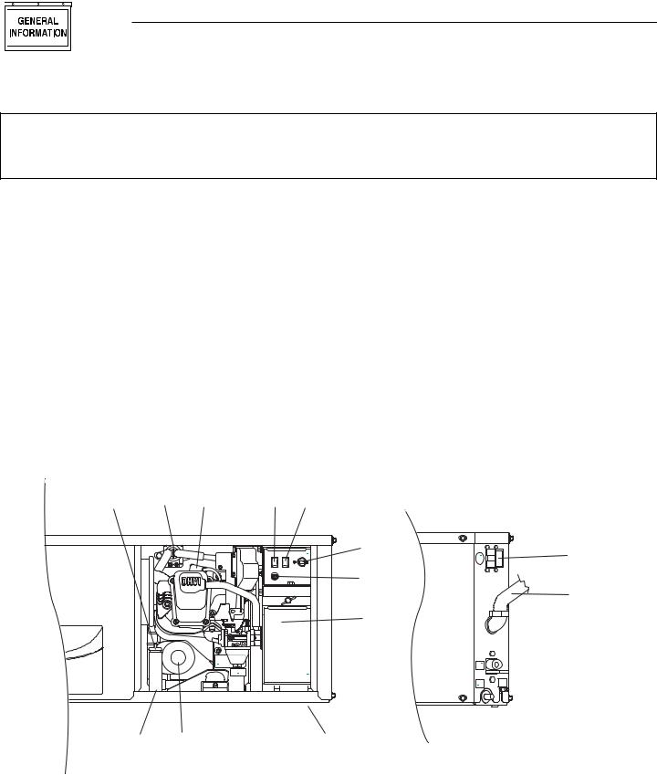
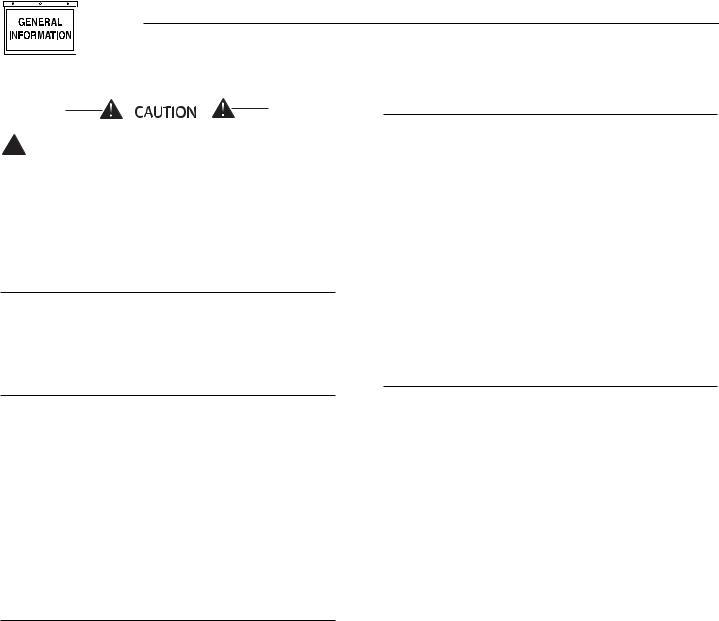
Model: 004700-0 — QUIETPACT 40G
1. |
Generator Air Intake |
9. |
Fuel Inlet |
2. |
Engine Start/Stop Switch |
10. |
Fuel Pump (Behind Access Panel) |
3. |
Fuse |
11. |
Fuel Filter (Side View) |
4. |
Optional Remote Panel Receptacle |
12. |
Oil Filter |
|
(Side View) |
13. |
Oil Drain Cap |
5. |
Generator AC Output Leads (Side |
14. |
Oil Dipstick |
|
View) |
15. |
Air Filter (Behind Access Panel) |
6. |
Fuel Primer Switch |
16. |
Oil Fill |
7. |
Circuit Breaker |
17. |
Spark Plug |
8. |
Starter Contactor |
|
|
14,16 |
8 |
17 |
2 |
6 |
C
|
r , W |
I |
w a t e |
|
RAC OHVI INDUSTRIAL ENGINE
PACT 40G
CONTROL CENTER |
|
|
S T A R T |
F U E L |
C . B . |
3 0 A |
||
S T O P |
P R I M E |
|
|
F U S E |
|
|
1 5 A |
|
S E R V IC E A C C E S S P A N E L |
||
AIR FILTER LOCATED BEHIND PANEL. |
|
|
MAINTENANCE SCHEDULE |
|
|
OIL LEVEL: |
CHECK DAILY |
|
AIR FILTER: |
CLEAN PREFILTER |
|
|
EVERY 100 HOURS. * |
|
|
REPLACE ELEMENT |
|
|
EVERY 250 HOURS. * |
|
OIL & OIL FILTER: |
CHANGE EVERY 100 |
|
|
HOURS. (OR ANNUALLY) * |
|
|
* |
|
SPARK PLUGS: |
INSPECT & CLEAN |
|
|
PLUGS EVERY 100 |
|
|
HOURS. REPLACE PLUGS |
|
|
EVERY 500 HOURS. |
|
|
(IF NECESSARY) |
|
FUEL FILTER: |
CHANGE EVERY 400 |
|
|
HOURS. (OR ANNUALLY) |
|
REPLACEMENT INFORMATION |
|
|
PREFILTER P/N: |
|
0D4511 |
AIR FILTER P/N: |
|
0D3262 |
OIL FILTER P/N: |
|
070185 |
SPARK PLUG P/N: |
|
072347 |
FUEL FILTER P/N: |
|
0D7515 |
OIL CAPACITY WITH FILTER: |
0.8L/0.84QT |
|
TEMPERATURE |
SAE VISCOSITY |
|
32˚F AND HIGHER |
|
30 |
10˚F TO 100˚F |
|
15W-40 |
0˚F TO 80˚F |
|
10W-30 |
-20˚F TO 50˚F |
|
5W-30 |
WHEN SERVICE OR PARTS ARE NEEDED IN
THE USA OR CANADA, CONTACT THE GENERAC
SERVICE LOCATOR AT 1-800-333-1322.
RV SERVICE LOCATOR: 1.800.333.1322
7 |
4 |
|
3
5
10/15

 9/11
9/11
13 |
12 |
1 |
4 Generac® Power Systems, Inc.
Section 1 – General Information
QUIETPACT 40G Recreational Vehicle Generator
1.2GENERATOR APPLICABILITY
These generators have been designed and manufactured for supplying electrical power for recreational vehicles. You should not modify the generator or use it for any application other than for what it was designed. If there are any questions pertaining to its application, write or call the factory. Do not use the unit until you have been advised by a competent authority.

 DANGER
For fire safety, the generator must have been properly installed in compliance with ANSI
119.2-1975/NFPA 501C-1974, “Standard for Recreational Vehicles, Part III – Installation of Electrical Systems.” The generator also must have been installed in strict compliance with the manufacturer’s detailed installation instructions. After installation, do nothing that might render the unit in noncompliance with such codes, standards and instructions.
You can use this generator to supply electrical power for operating 120-volt, single-phase, 60 Hertz, AC electrical loads. These loads can require up to 3,600 watts (3.6 kW) of power, but cannot exceed 30 AC amperes of current at 120 volts.
Do not overload the generator. Some installa-
!tions may require that electrical loads be alternated to avoid overloading. Applying excessively high electrical loads may damage the generator and may shorten its life. Add up the rated watts of all electrical lighting, appliance, tool and motor loads the generator will power at one time. This total should not be greater than the wattage capacity of the generator. If an electrical device nameplate gives only volts and amps, multiply volts times amps to obtain watts (volts x amps = watts). Some electric motors require more watts of power (or amps of current) for starting than for continuous operation.
1.3SAFETY
Before attempting to use the generator set, carefully read the “Safety Rules” section of this manual. Comply strictly with these rules to prevent accidents and damage to equipment and/or property. We suggest copying and posting the “Safety Rules” in potential hazard areas of the vehicle. Stress safety to all operators and potential operators of this equipment.
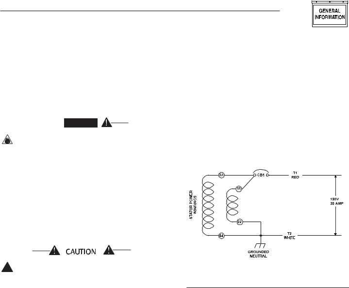
1.4GENERATOR AC
CONNECTION SYSTEM
This generator set is equipped with dual stator AC power windings. These two-stator windings supply electrical power to customer electrical loads by means of a two-wire connection system. Note, however, that the neutral is bonded to the frame of the engine-generator.
The generator may have been installed so that it powers 120-volt AC loads (Figure 1.1). It can be wired to connect 120-volt AC electrical loads. This procedure should be done by a Generac Authorized Service Dealer or other qualified installer.
Figure 1.1 – Connections for 120 Volts Only
1.5SPECIFICATIONS
1.5.1 FUEL REQUIREMENTS
The QUIETPACT series generator is equipped with a gasoline fuel system. Depending on the installation, the generator may have either a separate fuel tank, or it may “share” the vehicle engine’s fuel tank.
NOTE:
Some installations using a “shared” fuel tank may have a generator fuel pickup tube that is shorter than the vehicle engine’s pickup tube. Such an arrangement causes the generator engine to “run out of gas” while adequate fuel for the vehicle remains in the tank.
To reduce lead and carbon deposits use high quality UNLEADED gasoline with the generator. Leaded REGULAR grade gasoline is an acceptable substitute.
NOTE:
Using unleaded gasoline contributes to longer engine valve life by reducing lead and carbon deposits.
Generac® Power Systems, Inc. 5
Section 1 – General Information
QUIETPACT 40G Recreational Vehicle Generator
1.5.5 GENERATOR
Generac does not recommend using any
!gasoline containing alcohol (such as “gasohol”). If you use any gasoline containing alcohol, it must not contain more than 10 percent ethanol, and it must be removed from the generator during storage. Do NOT use any gasoline containing methanol. If you use gasoline with alcohol, inspect more frequently for fuel leaks and other abnormalities.
1.5.2 FUEL CONSUMPTION
Model |
No Load |
1/2 Load |
Full Load |
QUIETPACT 40G |
0.24 |
0.35 |
0.55 |
(004700-0) |
|
|
|
|
|
|
|
Fuel consumption is in gal/h.
1.5.3 ENGINE OIL REQUIREMENTS
Use only high quality detergent oil rated with American Petroleum Institute (API) Service Classification SF, SG or SH. The recommended oil weights include the following:
•During summer months: SAE 30. An acceptable substitute is SAE 10W-30.
•During winter months: SAE 5W-30. DO NOT USE SAE 10-W40.
Crankcase and oil filter capacity is approximately 800 mL or .84 U.S. quarts. Do NOT use special additives. See Sections 3.1 and 3.2 (Page 12) for oil level check and fill procedures.
Rated Maximum Continuous |
|
AC Output (Gasoline) ............................ |
3,600 Watts (3.6 kW) |
Rated Voltage ........................................................ |
120 Volts AC |
Rated Maximum Continuous |
|
AC Current (Gasoline).......................................... |
30 Amperes |
Phase ................................................................................ |
Single |
Rotor RPM ........................................................................ |
3,600 |
Number of Rotor Poles ............................................................ |
2 |
Engine RPM ...................................................................... |
3,600 |
Rated AC Frequency ........................................................ |
60 Hz |
Battery Charge Voltage............................................ |
14 Volts DC |
Battery Charge Current.................................. |
2 Amperes (max) |
Gasoline weight ...................................................... |
170 Pounds |
Length .................................................... |
749.8 mm (29.52 in.) |
Width ...................................................... |
483.1 mm (19.02 in.) |
Height ...................................................... |
342.2 mm (13.47 in.) |
1.5.6 EMISSIONS COMPLIANCE PERIOD
For non-handheld engines the Emissions Compliance Period referred to on the Emissions Compliance Label indicates the number of operating hours for which the engine has been shown to meet Federal emission requirements.
•For engines less than 225 cc displacement, Category C=125 hours, B=250 hours, and A=500 hours.
•For engines of 225 cc or more, Category C=250 hours, B=500 hours, and A=1000 hours.
1.5.4 ENGINE
Type of Engine .................................... |
|
GN - 220, Single-cylinder |
Cooling Method.......................................................... |
|
Air-cooled |
Rated Horsepower ........................................ |
|
7.8 @ 4,200 rpm |
Displacement.................................................................... |
|
220cc |
Cylinder Block .......................... |
Aluminum w/Cast Iron Sleeve |
|
Type of Governor .............................. |
|
Mechanical, Fixed Speed |
Air Cleaner.......................... |
Paper Element w/Foam Precleaner |
|
Starter.......................................................... |
|
12-volt DC Electric |
Ignition System........................ |
Solid-state w/Flywheel Magneto |
|
Recommended Spark Plug |
|
|
Champion .................................................................. |
|
RC12YC |
AC.................................................................................... |
|
R45S |
Fram Autolite ...................................................................... |
|
65 |
Spark Plug Gap ........................................ |
|
0.030 inch (76 mm) |
Recommended Minimum Battery |
..............400 Cold-cranking |
|
|
|
Amperes |
6 Generac® Power Systems, Inc.
Section 2 – Operation
QUIETPACT 40G Recreational Vehicle Generator
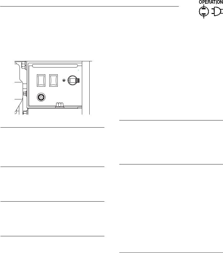
2.1GENERATOR CONTROL PANEL
The following features are mounted on the generator control panel (Figure 2.1):
Figure 2.1 – Generator Control Panel
CONTROL CENTER
S T A R T |
F U E L |
C . B . |
|
3 0 A |
|||
|
|
2.2OPTIONAL REMOTE
START/STOP PANEL
A remote mounted Start/Stop Panel is available that allows you to start and stop the generator engine conveniently from inside the vehicle.
You can order model 4057 or 4184, a remote panel that includes a Start/Stop switch, a generator run lamp and an hourmeter. The hourmeter provides a continuous indication of engine/generator operating time. Use the hourmeter for checking off periodic maintenance requirements on the unit.
S T O P P R I M E
F U S E
7. 5 A
2.3AUTOMATIC CHOKE
The engine is equipped with an automatic choke that consists of two main components: a choke solenoid and prechoke.
2.1.1 FUEL PRIMER
Before starting a cold engine (if it has not been started in more than two weeks), you must press this switch for approximately 10 to 15 seconds to bring fuel from the tank to the carburetor. This rocker type switch springs back into its original position when you release it.
2.1.2 START/STOP SWITCH
To crank and start the engine, hold this switch in the START position. Release the switch when the engine starts. To stop an operating engine, press and hold the switch in the STOP position until the engine shuts off. The switch center position is the RUN position.
2.1.3 FUSE
The fuse protects the engine’s DC control circuit against electrical overload. If the fuse element has melted open due to overloading, the engine cannot be cranked. If you must replace the fuse, use only an identical replacement.
2.1.4 MAIN BREAKER
The main breaker protects the generator’s AC output circuit against overload and provides a method of turning OFF the generator’s 120-volt AC output to the vehicle circuits. The QUIETPACT 40G has 30-amp breaker.
2.3.1 CHOKE SOLENOID
During engine cranking (Start/Stop switch at START), a solid-state choke module signals the choke solenoid to activate and cycle (choke on/choke off) until the engine starts. The choke solenoid thus opens and closes the carburetor choke valve only when the engine is cranking. When the engine starts, the choke stops cycling.
2.3.2 PRECHOKE
The choke system also has a temperature-sensitive metal strip that adjusts choke valve angle according to ambient temperatures (i.e., in cold ambient temperatures, choke valve closes more). Once the engine starts, an element heats the temperature-sensitive strip to a normal operating condition, opening the choke valve. This may take about three minutes in cooler weather.
2.4BEFORE STARTING THE ENGINE
NOTE:
Instructions and information in this manual assume the generator has been properly installed, connected, serviced, tested and adjusted by a qualified installation technician or installation contractor.
2.4.1 INSTALLATION
Generator installation must have been properly completed so it complies with all applicable codes, standards and regulations and with the manufacturer's recommendations.
Generac® Power Systems, Inc. 7

Section 2 – Operation
QUIETPACT 40G Recreational Vehicle Generator
2.4.2 ENGINE LUBRICATION
Have the engine crankcase properly serviced with the recommended oil before starting. Refer to Section 1.5.4 (Page 6) and Sections 3.1 and 3.2 (Page 12) for oil servicing procedures and recommendations.
Any attempt to crank or start the engine before
!you have properly serviced it with the recommended oil may result in an engine failure.
2.4.3 FUEL SUPPLY
The engine must have an adequate supply of proper fuel to operate. Before starting it, check that sufficient fuel is available.
NOTE:
Depending on the installation, the generator may have either a separate fuel tank, or it may “share” the vehicle engine’s fuel tank.
2.4.4 COOLING AND VENTILATING AIR
Air inlet and outlet openings in the generator compartment must be open and unobstructed for continued proper operation. Without sufficient cooling and ventilating airflow, the engine/generator quickly overheats, which causes it to shut down and may damage the generator.
2.4.5 ENGINE EXHAUST GAS
Before starting the generator engine, you should be sure there is no way for exhaust gases to enter the vehicle interior and endanger people or animals. Close windows, doors and other openings in the vehicle that, if open, might permit exhaust gases to enter the vehicle.

 DANGER
The generator engine releases DEADLY carbon
!monoxide gas through its exhaust system. This dangerous gas, if breathed in sufficient concentrations, can cause unconsciousness or even death. Never operate the generator set with the vehicle inside any garage or other enclosed area. DO NOT OPERATE THE GENERATOR IF THE EXHAUST SYSTEM IS LEAKING OR HAS BEEN DAMAGED. SYMPTOMS OF CARBON MONOXIDE POISONING ARE (a) inability to think coherently, (b) nausea, (c) vomiting, (d) twitching muscles, (e) throbbing temples, (f) dizziness, (g) headaches, (h) weakness, and (i) sleepiness. IF YOU EXPERIENCE ANY OF THESE SYMPTOMS, MOVE INTO FRESH AIR IMMEDIATELY. IF SYMPTOMS PERSIST, GET MEDICAL HELP. Shut down the generator and do not operate it until it has been inspected and repaired.
8 Generac® Power Systems, Inc.

 DANGER
Never sleep in the vehicle while the genset is
!running unless the vehicle has a working carbon monoxide detector. The exhaust system must be installed in accordance with the genset installation manual. Make sure there is ample fresh air when operating the genset in a confined area.
2.5STARTING THE GENERATOR
NOTE:
Read the vehicle manufacturer’s instructions. The owner/operator should become familiar with the vehicle in which this generator is installed. Differences exist between vehicles. For example, some vehicles may use a transfer switch to isolate dockside power from the generator, while other vehicles may use an isolating receptacle. Some vehicles may be equipped with a DC converter, which allows the generator to power certain DC lighting and other DC loads.
To start the generator from either the generator control panel or from the optional remote panel, proceed as follows:
1.Turn OFF electrical loads using the means provided in your vehicle (such as a main line circuit breaker or transfer switch).
NOTE:
If starting from the generator control panel, turn OFF loads by setting the generator’s main circuit breaker to the OFF (or open) position. If starting from a remote panel, turn OFF loads using the means provided in the vehicle (such as a main circuit breaker). Electrical load circuits will be turned ON after the generator has started, stabilized and warmed up.
2.If you have not started the engine in more than two weeks, press the Fuel Pump Primer switch and hold it for about 10 to 15 seconds to prime the fuel system. However, if the engine is warm, skip Step 2.
3.Hold the engine Start/Stop switch in the START position to crank the engine. Release the switch when the engine starts.
If the engine does not start after it has been
!cranking for 15 seconds, release the Start/Stop switch, wait one minute and try again. Holding the switch for longer than 15 seconds can damage the starter motor.
4.Let the engine run at no-load for a few minutes to stabilize and warm up.
5.Turn ON electrical loads using the means provided (such as a main circuit breaker or transfer switch).
Section 2 – Operation
QUIETPACT 40G Recreational Vehicle Generator
2.6STOPPING THE GENERATOR
1.Turn OFF all electrical loads using the means provided (such as a main circuit breaker or transfer switch).
2.Let generator run at no-load for a few minutes, to stabilize internal engine generator temperatures.
3.Place the Start/Stop switch in its STOP position.
2.7APPLYING LOADS TO GENERATOR
When applying electrical loads to the generator, observe these guidelines:
•Induction type motors (such as those that run the vehicle’s furnace fan, refrigerator, air conditioner, etc.) need about 2-1/2 time more watts of power for starting than for running (for a few seconds during motor starting). Be sure to allow for this when connecting electrical loads to the generator. First, figure the watts needed to start electric motors in the system. To that figure, add the running wattages of other items that will be operated by the generator.
•Do not apply heavy electrical loads for the first two or three hours of operation.
•Before applying electrical loads, let the generator stabilize and warm up for a minute or two.
•DO NOT overload the generator.
2.7.1 LETTING THE ENGINE STABILIZE
The generator supplies correct rated voltage only at the proper governed speed. Some electrical appliances may be extremely sensitive to voltage. Incorrect voltages can damage such appliances.
If electrical loads are applied at reduced operating speeds, such loads imposed on the engine when sufficient power is not available may shorten engine life. Never turn ON electrical loads until after the generator engine has started and stabilized at no-load.
2.8DO NOT OVERLOAD THE
GENERATOR
You can read the rated wattage/amperage capacity of your generator on the generator data decal (see Section 1.1 on Page 4).
Applying electrical loads in excess of the unit’s rated capacity will cause the engine/generator to automatically shut down.
To avoid overloading, add up the wattage of all connected electrical lighting, appliance, tool and motor loads. This total should not be greater than the generator’s rated wattage capacity.
•Most lighting, appliance, tool and motor loads indicate their required watts on their nameplate or data plate. For light bulbs, simply note the wattage rating of the bulb.
•If a load does not show its rated wattage, multiply that load’s rated VOLTS times AMPS to obtain WATTS.
2.9PROTECTION SYSTEMS
2.9.1 LOW OIL PRESSURE SWITCH
This switch (Figure 2.2) has normally closed (N.C.) contacts that are held open by engine oil pressure during cranking and operating. Should oil pressure drop below a preset level, switch contacts close, and the engine automatically shuts down. The unit should not be restarted until oil is added.
2.9.2 HIGH TEMPERATURE SWITCH
This switch (Figure 2.2), which has normally open (N.O.) contacts, is mounted near the oil filter. The contacts close if the temperature should exceed approximately 293º F (145º C), initiating an engine shutdown.
Figure 2.2 – Low Oil Pressure and
High Temperature Switches
High Temperature Switch
Low Oil Pressure
Switch
Generac® Power Systems, Inc. 9
Section 2 – Operation
QUIETPACT 40G Recreational Vehicle Generator
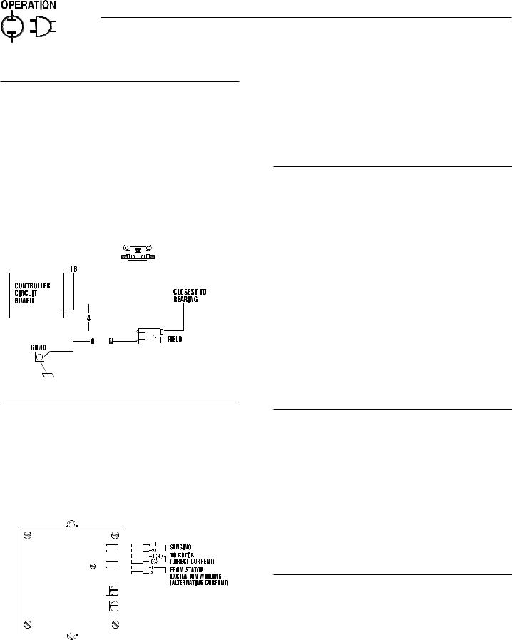
2.9.3 FIELD BOOST
The Controller Circuit Board houses a field boost diode and resistor that are not part of the automatic choke circuit. These two components are part of a “field boost” circuit (Figure 2.3). During engine cranking only, a positive DC (battery) voltage is delivered through the diode, resistor, brushes and slip rings, to the generator rotor. Application of this voltage to the rotor “flashes the field” whenever it is started. Flashing of the field each time the generator starts makes sure that a sufficiently strong magnetic field is available to produce “pickup” voltage in the stator windings.
Figure 2.3 – Field Boost Circuit
The voltage regulator also incorporates a “voltage surge protection circuit.” This circuit prevents troublesome surges in the generator AC output voltage. Voltage surge is a common cause of damage to electronic equipment.
2.10 ADDITIONAL INFORMATION
2.10.1 25-HOUR BREAK-IN PERIOD
The first 25 hours of operation is the break-in period for the generator. Properly breaking in the generator is essential to minimize fuel consumption and provide maximum engine performance. During this 25hour break-in period, follow this procedure:
•Run the unit at varying electrical loads to help seat the engine piston rings properly.
•Check the engine oil level frequently. Add oil if needed. It is normal for the generator engine to consume more oil than is normal until the piston rings have properly seated.
•For the 75-hour operation following the break-in period, avoid light electrical loads. Load the generator at 50 percent (or more) of its rated wattage capacity. Repeated light loads during these 75 hours can cause improper seating of engine piston rings, resulting in blowby and high oil consumption.
•After operating the unit for 25 hours, complete the tasks recommended under Section 2.10.2.
2.9.4 OVERVOLTAGE PROTECTION
A solid-state voltage regulator (Figure 2.4) controls the generator’s AC output voltage. This regulator supplies an excitation current to the rotor. By regulating the rotor’s excitation current, the strength of its magnetic field is regulated and, in turn, the voltage delivered to connected electrical loads is controlled. When the AC frequency is 60 Hertz, voltage is regulated at 120 volts (voltage-to-frequency ratio is 2-to-1).
Figure 2.4 – Solid State Voltage Regulator
2.10.2 25-HOUR CHECK-UP
After the 25-hour break-in period, contact a Generac Authorized Service Dealer for the following maintenance. The vehicle owner is responsible for any charges:
•Change the engine crankcase oil and oil filter.
•Check the oil level.
•Inspect the cooling and ventilation openings.
•Check the engine carburetor adjustments.
•Check the engine ignition system.
•Inspect the entire electrical system.
•Inspect the engine exhaust system.
2.10.3 ATTENTION REQUIRED
AFTER SUBMERSION
If the recreational vehicle generator has been submerged in water, it MUST NOT be started and operated. Following any submersion in water, have a Generac Authorized Service Dealer thoroughly clean and dry the generator.
10 Generac® Power Systems, Inc.
Section 3 – Maintenance
QUIETPACT 40G Recreational Vehicle Generator
2.10.4 OPERATION IN HIGH GRASS OR BRUSH
Never operate the generator while the vehicle is parked over high grass, weeds, brush, leaves or any other combustible substance. Such materials can ignite and burn from the heat of the exhaust system. The generator exhaust system becomes extremely hot during operation and remains hot for a long time after it has shut down.
2.10.5 EFFECTS OF MOISTURE AND DIRT
Keep the generator set as clean and dry as possible. Protect the unit against excessive dust, dirt, corrosive vapors, road splash, etc. Permitting dirt and moisture to accumulate on generator windings will have an adverse effect on the insulation resistance of those windings.
When moisture is allowed to remain in contact with windings, some of the moisture will be retained in voids and cracks in the insulation. This causes a reduced insulation resistance and will eventually cause problems. Dirt will make the problem worse, since dirt tends to hold moisture in contact with windings. Salt (as from sea air) also will worsen the problem since it tends to absorb moisture from the air. Salt and moisture, when combined, form a good electrical conductor.
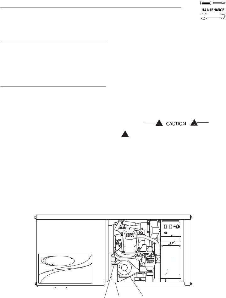
3.1CHECKING THE ENGINE OIL
LEVEL
For oil capacities and requirements, see “Engine Oil Requirements,” Section 1.5.4 (Page 6). Check the engine crankcase oil level at least every eight hours of operation, or before you use it. To check the engine oil level, proceed as follows (see Figure 3.1):
1.Be sure the generator is as level as possible.
2.Remove the dipstick and wipe it dry with a clean, lint-free cloth.
3.Install and tighten the dipstick cap; then, remove it again. The oil level should be at the dipstick “Full” mark.
4.If necessary, remove the oil fill cap on the rocker cover and slowly add oil until it reaches the dipstick “Full” mark. DO NOT FILL ABOVE THE “FULL” MARK.
Never operate the engine with the oil level
!below the “Add” mark on the dipstick. Doing this could damage the engine.
5.Install and tighten the oil fill cap and the dipstick before operating the engine.
3.2CHANGING THE ENGINE OIL
AND/OR OIL FILTER
•Change the engine oil after the first 25 hours of operation (after the 25-hour break-in period, see Section 2.10.1, Page 10). Thereafter, change the oil every 100 operating hours. Change the oil more frequently if operating consistently under heavy load or at high ambient temperatures.
Figure 3.1 – Oil Maintenance Features
GENERAC |
|
|
||
OHVIPOWERED |
I |
To Re |
||
G E N E R A C |
P o w e r S y s t e m s , I n c .- W h it e |
w a t e r , W |
|
|
|
|
|
m |
|
|
|
|
|
o |
|
|
|
|
v |
|
|
|
|
e |
GENERAC OHVI INDUSTRIAL ENGINE
TM
QUIETPACT 40G
CONTROL CENTER
S T A R T |
F U E L |
C . B . |
3 0 A |
||
S T O P |
P R I M E |
|
|
F U S E |
|
|
7.5 A |
|
S E R V IC E A C C E S S P A N E L
AIR FILTER LOCATED BEHIND PANEL.
MAINTENANCE SCHEDULE
OIL LEVEL: |
CHECK DAILY |
AIR FILTER: |
CLEAN PREFILTER |
|
EVERY 100 HOURS. * |
|
REPLACE ELEMENT |
|
EVERY 250 HOURS. * |
OIL & OIL FILTER: |
CHANGE EVERY 100 |
|
HOURS. (OR ANNUALLY) * |
|
* |
SPARK PLUGS: |
INSPECT & CLEAN |
|
PLUGS EVERY 100 |
|
HOURS. REPLACE PLUGS |
|
EVERY 500 HOURS. |
|
(IF NECESSARY) |
FUEL FILTER: |
CHANGE EVERY 400 |
|
HOURS. (OR ANNUALLY) |
REPLACEMENT INFORMATION
PREFILTER P/N: |
0D4511 |
AIR FILTER P/N: |
0D3262 |
OIL FILTER P/N: |
070185 |
SPARK PLUG P/N: |
072347 |
FUEL FILTER P/N: |
0D7515 |
OIL CAPACITY WITH FILTER: |
0.8L/0.84QT |
TEMPERATURE |
SAE VISCOSITY |
32˚F AND HIGHER |
30 |
10˚F TO 100˚F |
15W-40 |
0˚F TO 80˚F |
10W-30 |
-20˚F TO 50˚F |
5W-30 |
WHEN SERVICE OR PARTS ARE NEEDED IN
THE USA OR CANADA, CONTACT THE GENERAC
SERVICE LOCATOR AT 1-800-333-1322.
RV SERVICE LOCATOR: 1.800.333.1322
Oil Dipstick/Oil Fill Oil Drain Oil Filter
Generac® Power Systems, Inc. 11
Section 3 – Maintenance
QUIETPACT 40G Recreational Vehicle Generator
•Change the engine oil filter after the first 25 hours of operation, and every 100 operating hours thereafter.
To change the oil and/or oil filter, proceed as follows (see Figure 3.1):
1. Run the engine until it is thoroughly warmed up (at least five minutes) then shut OFF the engine.
2.Immediately after the engine shuts OFF, pull the oil drain cover free of the base. Remove the plug from the tube with a 5/16” allen wrench and drain the oil into a suitable container. Loosening the oil fill cap will allow the crankcase to drain faster.
3.After the oil has drained, replace the plug onto the end of the oil drain tube. Retain the cover in the base.
4.With the oil drained, remove the old oil filter by turning it counterclockwise. Place a towel underneath to catch excess oil.
5.Apply a light coating of clean engine oil to the gasket of the new filter. Fill the filter until saturated with clean oil.
6.Screw the new filter on by hand until its gasket lightly contacts the oil filter adapter. Then, tighten the filter an additional 3/4 to one turn.
7.Remove the dipstick and wipe it dry with a clean, lint-free cloth. This will be used later to check the oil level.
8.Remove the oil fill cap on the oil fill tube and slowly add the proper type and amount of recommended oil (see Section 1.5.4, Page 6). Periodically use the dipstick to check the oil level and continue to fill the crankcase until the oil reaches the dipstick “Full” mark. DO NOT FILL ABOVE THE “FULL” MARK.
9.Install and tighten the oil fill cap and the dipstick before operating the engine.
10.Start the engine and check for leaks.
NOTE:
Check the oil level and fill to the “FULL” mark after checking for leaks. The filter will retain some oil.
3.3MAINTAINING THE ENGINE AIR CLEANER
3.3.1 CLEANING THE FOAM PRECLEANER
3.Remove the foam precleaner from the cover.
4.Wash the foam precleaner in liquid detergent and water.
5.Wrap the foam precleaner in a clean cloth and gently squeeze it dry.
6.Saturate the foam precleaner in clean engine oil. Gently squeeze it in a clean cloth to remove excess oil and to distribute oil (DO NOT TWIST).
7.Install the foam precleaner into the cover, followed by the paper filter.
8.Install the cover, foam precleaner and paper filter.
9.Tighten the two screws to retain the filter in place.
Figure 3.2 – Engine Air Cleaner
3.3.2 CLEANING OR REPLACING THE PAPER FILTER
Once each year or every 100 hours of operation (whichever comes first), clean or replace the paper filter. The new replacement filter must be flame retardant. Service the paper filter more frequently if operating the generator in extremely dusty or dirty conditions. Use the following procedure (Figure 3.2):
1.Follow steps 1-3 in Section 3.3.1; service the foam precleaner if necessary.
2.Remove the paper filter.
3.Clean the air filter by tapping it gently on a solid surface. If the filter is too dirty, replace it with a new one. Dispose of the old filter properly.
4.Clean the air cleaner cover then reassemble following steps 7-9 in Section 3.3.1.
Clean and re-oil the foam precleaner every three months or every 25 hours of operation, whichever occurs first. Service the foam precleaner more frequently if operating the generator in extremely dusty or dirty conditions. Use the following procedure (Figure 3.2):
1.Turn the two screws counterclockwise to loosen.
2.Remove the cover, foam precleaner and paper filter.
12 Generac® Power Systems, Inc.
Section 3 – Maintenance
QUIETPACT 40G Recreational Vehicle Generator
3.4CLEAN AIR INTAKE
Clean all foreign material from the air intake (Figure 3.3) at least once every 100 hours of operation. Clean more often if necessary.
Inspect the area around the generator exhaust muffler periodically and remove all grass, leaves, dirt, etc., from this area.
Figure 3.3 – Cleaning Air Intake
USTC
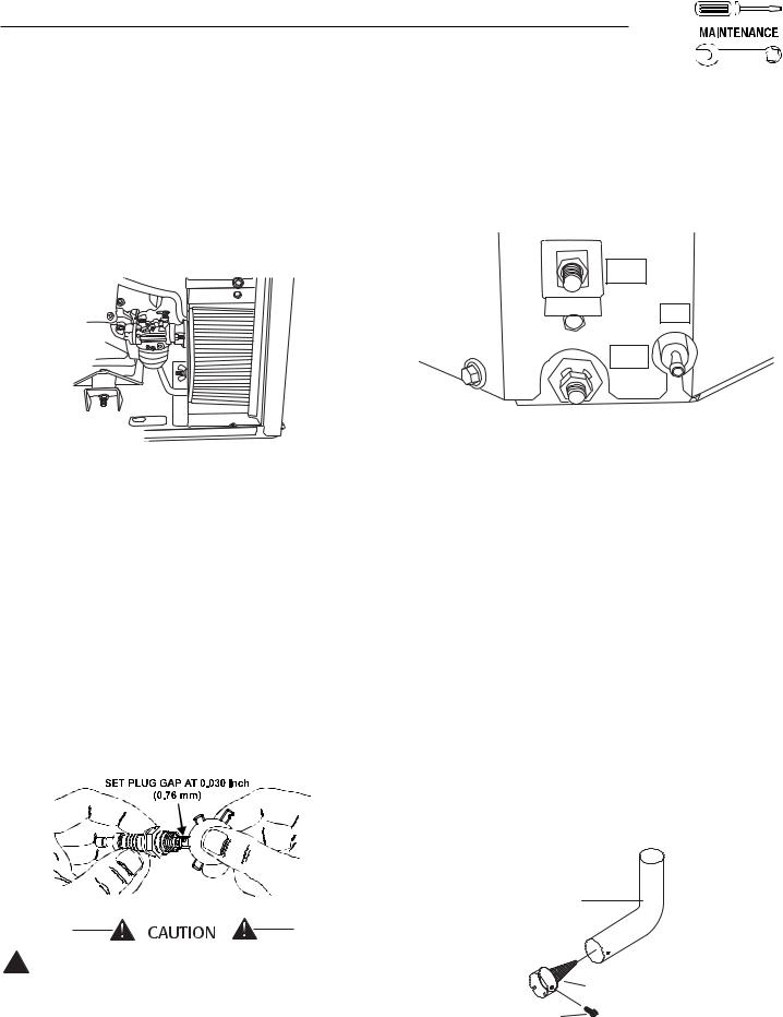
3.5CHECKING THE ENGINE
SPARK PLUG
Clean the spark plug and reset the spark plug gap every 100 hours of operation.
1.Clean the area around the base of the spark plug to keep dirt and debris out of the engine. Remove the spark plug and check the condition. Replace the spark plug if worn or if reuse is questionable.
2.Clean spark plug by scraping or washing using a wire brush and commercial solvent. Do not blast the spark plug to clean.
3.Check the spark plug gap using a wire feeler gauge. Adjust the gap to 0.030 inch (0.76 mm) by carefully bending the ground electrode (Figure 3.4).
Figure 3.4 – Setting the Spark Plug Gap
Sparking can occur if the wire terminal does
!not fit firmly on the spark plug terminal end. If necessary, re-form the wire terminal to obtain a tight fit.
3.6FUEL FILTER
Remove and replace the fuel filter (Figure 3.5) once each year or every 400 hours of operation, whichever comes first. Fuel filter is removed with a 15/16” deep well socket.
Figure 3.5 – Fuel Filter
POS
FUEL
NEG
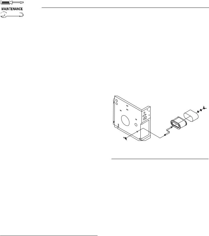
3.7CLEAN SPARK ARRESTOR
The engine exhaust muffler has a spark arrestor screen. Inspect and clean the screen every 50 hours of operation or once each year, whichever comes first.
NOTE:
If you use your generator on any forest-covered, brush-covered or grass-covered unimproved land, it must equipped with a spark arrestor. The spark arrestor must be maintained in good condition by the owner/operator.
Clean and inspect the spark arrestor as follows:
•Remove the screen retaining bracket by removing the screw.
•Slide the spark arrestor screen out from the tail pipe.
•Inspect screen and replace if torn, perforated or otherwise damaged. DO NOT USE a defective screen. If screen is not damaged, clean it with commercial solvent.
•Replace the screen and the retaining bracket.
Figure 3.6 - Spark Arrestor
TAILPIPE
P/N 0E0683
SPARK ARRRESTOR
SCREEN P/N 089680
RETAINING
SCREW P/N 056892
Generac® Power Systems, Inc. 13
Section 3 – Maintenance
QUIETPACT 40G Recreational Vehicle Generator
3.8CLEANING THE GENERATOR
Keep the generator set as clean and dry as possible. Protect the unit against excessive dust, dirt, corrosive vapors, road splash, etc. Permitting dirt and moisture to accumulate on generator windings will have an adverse effect on the insulation resistance of those windings.
When moisture is allowed to remain in contact with windings, some of the moisture will be retained in voids and cracks in the insulation. This causes a reduced insulation resistance and will eventually cause problems. Dirt will make the problem worse, since dirt tends to hold moisture in contact with windings. Salt (as from sea air) also will worsen the problem since it tends to absorb moisture from the air. Salt and moisture, when combined, form a good electrical conductor which can be damaging to the generator windings.
Do NOT use a forceful spray of water to clean
!the generator. Water will enter the generator interior and cause problems, and may also contaminate the generator fuel system.
3.9BATTERY MAINTENANCE
All lead-acid batteries will discharge when not in use. The generator battery should be inspected as follows:
3.9.1 WEEKLY
•Inspect the battery posts and cables for tightness and corrosion. Tighten and clean as necessary.
•Check the battery fluid level of unsealed batteries and, if necessary, fill with Distilled Water Only. Do not use tap water in batteries.
3.9.2 EVERY SIX MONTHS
•Have the state of charge and condition checked. This should be done with an automotive-type battery hydrometer.
NOTE:
Servicing of the battery is to be performed or supervised by personnel knowledgeable of batteries and the required precautions. Keep unauthorized personnel away from batteries.
Damage will result if the battery connections are made in reverse.

 DANGER
Do not dispose of the battery in a fire. The battery is capable of exploding. Storage batteries give off explosive hydrogen gas. This gas can form an explosive mixture around the battery for several hours after charging. The slightest spark can ignite the gas and cause an explosion. Such an explosion can shatter the battery and cause blindness or other injury. Any area that houses a storage battery must be properly ventilated. Do not allow smoking, open flame, sparks, or any spark producing tools or equipment near the battery. Discharge static electricity from your body before touching the battery by first touching a grounded metal surface.
A battery presents a risk of electrical shock and high short circuit current. The following precautions are to be observed when working on batteries:
•Remove watches, rings or other metal objects;
•Use tools with insulated handles;
•Wear rubber gloves and boots;
•Do not lay tools or metal parts on top of the battery;
•Disconnect any charging source prior to connecting or disconnecting battery terminals; and
•Do not use any jumper cables or booster battery to crank and start the generator engine. If any battery has discharged, remove it for recharging.
Do not open or mutilate the battery. Released
!electrolyte has been known to be harmful to the skin and eyes, and to be toxic.
The electrolyte is a dilute sulfuric acid that is
!harmful to the skin and eyes. It is electrically conductive and corrosive. The following procedures are to be observed:
•Wear full eye protection and protective clothing;
•Where electrolyte contacts the skin, wash it off immediately with water;
•Where electrolyte contacts the eyes, flush thoroughly and immediately with water and seek medical attention; and
•Spilled electrolyte is to be washed down with an acid neutralizing agent. A common practice is to use a solution of 1 pound (500 grams) bicarbonate of soda to 1 gallon (4 liters) or water. The bicarbonate of soda solution is to be added until the evidence of reaction (foaming) has ceased. The resulting liquid is to be flushed with water and the area dried.
14 Generac® Power Systems, Inc.
 Loading...