


GP6500E-5941-2
GENERAC _
Owner'sM
GPSeriesPortableGenerator
introduction.............................................................1
Maintenance.........................................................13
ReadthisManual Thoroughly.................................1
Safety Rules...........................................................1
StandardsIndex.............................................................3
Generalinformation................................................4
1.1 Unpacking......................................................................4
1.1.1 Accessory Box..................................................4
1.2 Assembly.......................................................................4
1.2.1 Assemblingthe Accessory Kit............................4
1.2.2 BatteryCableConnection(ElectricStart Only)....5
Operation................................................................5
2.1 Knowthe Generator.......................................................5
2.2 Hourmeter......................................................................7
2.3 CordSets andConnectionPlugs....................................7
2.3.1 120 VAC,20 Amp, DuplexReceptacle...............7
2.3.2 120/240VAC,30 Amp, Receptacle....................7
2.3.3 120 VAC,20 Amp, GFCIDuplexReceptacle.......7
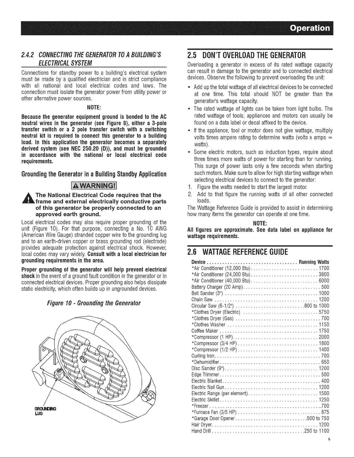
2.3.4 120/240VAC,30 Amp Receptacle.....................8
2.4 Howto Usethe Generator..............................................8
2.4.1 Groundingthe GeneratorWhenUsed
asa Portable.....................................................8
2.4.2 Connectingthe Generatorto a Building's
ElectricalSystem...............................................9
2.5 Don'tOverloadthe Generator..........................................9
2.6 WattageReferenceGuide...............................................9
2.7 BeforeStartingthe Generator.......................................10
2.7.1 Adding EngineOil............................................10
2.7.2 Adding Gasoline...............................................10
2.8 Starting Pull Start Engines............................................11
2.9 Starting ElectricStart Engines......................................11
2.9.1 ManualStart....................................................12
2.10 Stoppingthe Engine.....................................................12
2.11 Low Oil Level ShutdownSystem..................................12
2.11.1 SensingLow Oil Level......................................12
2.12 Chargingthe Battery(Electric Start Units Only).............12
3.1 PerformingScheduledMaintenance.............................13
3.2 MaintenanceSchedule.................................................13
3.3 ProductSpecifications..................................................13
3.3.1 GeneratorSpecifications..................................13
3.3.2 EngineSpecifications.......................................13
3.3.3 EmissionsInformation.....................................13
3.4 GeneralRecommendations...........................................13
3.4.1 GeneratorMaintenance....................................13
3.4.2 ToCleanthe Generator.....................................14
3.4.3 EngineMaintenance.........................................14
3.4.4 CheckingOil Level...........................................14
3.4.5 Changingthe Oil..............................................14
3.4.6 Replacingthe SparkPlug.................................14
3.4.7 BatteryReplacement(if applicable)..................14
3.5 ServiceAir Cleaner.......................................................15
3.5.1 CleanSparkArrestor Screen(CARDmodels)...15
3.6 ValveClearance............................................................15
3.7 General........................................................................15
3.8 Long TermStorage.......................................................16
3.9 OtherStorageTips.......................................................16
Troubleshooting....................................................17
4.1 TroubleshootingGuide..................................................17
Warranty...............................................................18
MANUALDELPROPIETARIO.............................23
MANUELD'ENTRETIEN......................................47
iNTRODUCTiON
Thankyou for purchasingthis model by GeneracPowerSystems,
Inc. This model is a compact, high performance, air-cooled,
engine driven generatordesigned to supply electrical power to
operateelectrical loads where no utility power is available or in
placeof utility dueto a poweroutage.
BEADTHISMANUALTHOROUGHLY
If anyportion ofthis manualis not understood,contactthenearest
AuthorizedDealerfor starting, operatingandservicingprocedures.
The operator is responsiblefor proper and safe use of the
equipment.We strongly recommend that the operator read this
manualandthoroughlyunderstandallinstructions beforeusingthe
equipment.Wealsostronglyrecommendinstructingother usersto
properlystart andoperatethe unit.This preparesthemifthey need
to operatetheequipmentin an emergency.Savetheseinstructions
for future reference.Ifyou loanthis unitto someone,ALWAYSloan
these instructionsto the individualas welt.
Thegeneratorcan operatesafely,efficiently and reliablyonly if it
is properlylocated, operatedandmaintained.Before operatingor
servicingthe generator:
• Becomefamiliarwith and strictly adhereto alt local, state and
nationalcodes and regulations.
• Study all safety warnings in this manual and on the product
carefully.
• Becomefamiliarwith this manualandthe unit beforeuse.
Themanufacturercannot anticipateevery possible circumstance
that might involvea hazard.The warnings inthis manual,and on
tags and decals affixedto the unit are, therefore,not all inclusive.
If using a procedure,work method or operatingtechniquethat the
manufacturerdoes not specifically recommend,ensurethat it is
safe for others. Also make sure the procedure,work method or
operatingtechniqueutilizeddoes not renderthe generatorunsafe.
THE INFORMATIONCONTAINEDHEREIN WAS BASED ON
MACHINESIN PRODUCTIONAT THE TIME OF PUBLICATION.
GENERACRESERVESTHERIGHTTOMODIFYTHISMANUALAT
ANYTIME.
SAFETYRULES
Throughoutthis publication,and on tags and decals affixedto the
generator,DANGER,WARNING,CAUTIONand NOTEblocks are
usedto alert personnelto special instructionsabout a particular
operation that may be hazardous if performed incorrectly or
carelessly.Observethem carefully.Their definitionsareasfollows:
INDICATES A HAZARDOUS SITUATION OR ACTION
WHICH, IF NOT AVOIDED, WILL RESULT IN DEATH
OR SERIOUS INJURY.
Indicates a hazardous situation or action which, if
not avoided, could result in death or serious injury.
_,CAUTION!
Indicates a hazardous situation or action which,
if not avoided, could result in minor or moderate
injury.
NOTE:
Notes containadditional informationimportantto a procedure
and will be found withinthe regulartextbody of thismanual.
These safety warnings cannot eliminate the hazards that they
indicate. Common sense and strict compliancewith the special
instructionswhile performing the action or serviceareessentialto
preventingaccidents.
Four commonly used safety symbols accompany the BANGER,
WARNINGand CAUTIONblocks. The type of information each
indicatesis as follows:
,_This symbol points out important safety
information that, if not followed, could
endanger personal safety and/or property of
others.
This symbol points out potential explosion
hazard.
i/_This symbol points out potential fire hazard.
This symbol points out potential electrical
shock hazard.
GENERAL HAZARDS
• NEVERoperatein an enclosed area, in a vehicle, or indoors
EVENIFdoors and windows areopen.
• For safety reasons, the manufacturer recommends that the
maintenanceof this equipmentis carried out by an Authorized
Dealer.Inspectthe generatorregularly,and contactthe nearest
AuthorizedDealerfor parts needingrepairor replacement.
• Operategeneratoronly on levelsurfacesandwhereit will notbe
exposedto excessivemoisture,dirt, dust or corrosivevapors.
• Keephands, feet, clothing, etc., awayfrom drive belts, fans,
and othermoving parts. Neverremoveany fan guardor shield
whilethe unit is operating.
• Certain parts of the generator get extremely hot during
operation. Keep clear of the generator until it has cooled to
avoidsevereburns.
• Do NOToperategeneratorinthe rain.
• Do not alter the construction of the generator or change
controlswhich might createan unsafeoperatingcondition.
• Neverstart or stop the unit with electrical loads connected
to receptaclesAND with connecteddevices turned ON. Start
the engine and let it stabilize before connecting electrical
loads. Disconnectall electricalloads beforeshutting down the
generator.
• Do not insert objectsthrough unit's cooling slots.
• When working on this equipment, remain alert at all times.
Never work on the equipment when physically or mentally
fatigued.
• Neverusethe generatoror anyof its parts as a step. Stepping
on the unit can stress and break parts, and may result in
dangerousoperating conditions from leaking exhaust gases,
fuel leakage,oil leakage,etc.
• Onelectricstart models, disconnectthe POSITIVE(+) battery
cable from the engine starter ORthe NEGATIVE(=) battery
cable from the battery terminal, whichever is easier, before
transportingthe generator.
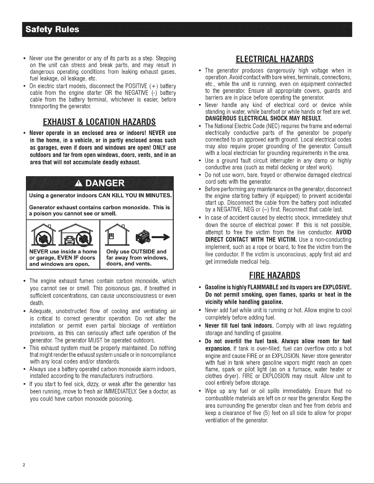
EXHAUST& LOCATIONHAZARDS
• Never operate in an enclosed area or indoors!NEVERuse
in the home, in a vehicle,or in partlyenclosed areassuch
as garages,evenif doors and windowsare open! ONLYuse
outdoors and far from openwindows,doors, vents,andinan
areathat will notaccumulatedeadly exhaust.
Using a generator indoors CAN KiLL YOU IN MINUTES,
Generator exhaust contains carbon monoxide. This is
a poison you cannot see or smell.
NEVER use inside a home
or garage, EVENIF doors
and windows are open.
Only use OUTSIDE and
far away from windows,
doors_ and vents,
ELECTRICALHAZARDS
• The generator produces dangerously high voltage when in
operation.Avoidcontactwith barewires,terminals,connections,
etc., while the unit is running, even on equipmentconnected
to the generator. Ensure all appropriate covers, guards and
barriersarein placebeforeoperatingthe generator.
• Never handle any kind of electrical cord or device while
standinginwater,while barefootorwhile handsor feet arewet.
DANGEROUSELECTRICALSHOCKMAYRESULT.
• TheNationalElectricCode(NEC)requirestheframe andexternal
electrically conductive parts of the generator be properly
connectedto an approvedearth ground.Local electricalcodes
may also require proper grounding of the generator.Consult
with a localelectricianfor groundingrequirementsin the area.
• Use a ground fault circuit interrupter in any damp or highly
conductivearea(such as metaldecking or steelwork).
• Do not useworn, bare,frayed or otherwisedamagedelectrical
cord setswith the generator.
• Beforeperforminganymaintenanceonthegenerator,disconnect
the enginestarting battery (if equipped)to prevent accidental
start up. Disconnectthe cable from the batterypost indicated
by a NEGATIVE,NEGor (-) first. Reconnectthatcable last.
• In caseof accident causedby electricshock, immediatelyshut
down the source of electrical power. If this is not possible,
attempt to free the victim from the live conductor. AVOID
DIRECTCONTACTWITHTHEVICTIM. Use a non-conducting
implement,such asa rope or board,to free thevictim from the
live conductor.If the victim is unconscious, applyfirst aid and
getimmediatemedical help.
• The engine exhaustfumes contain carbon monoxide, which
you cannot see or smell. This poisonous gas, if breathedin
sufficientconcentrations,can causeunconsciousnessor even
death.
• Adequate, unobstructed flow of cooling and ventilating air
is critical to correct generator operation. Do not alter the
installation or permit even partial blockage of ventilation
provisions, as this can seriously affect safe operationof the
generator.ThegeneratorMUSTbeoperatedoutdoors.
• Thisexhaustsystem must be properly maintained.Do nothing
that mightrendertheexhaustsystemunsafeorinnoncompliance
with any localcodes and/orstandards.
• Alwaysusea batteryoperatedcarbonmonoxidealarmindoors,
installedaccordingto themanufacturersinstructions.
• If you start to feet sick, dizzy,or weak after the generatorhas
beenrunning,moveto fresh air IMMEDIATELYSeea doctor,as
you couldhave carbonmonoxidepoisoning.
FIREHAZARDS
• Gasolineishighly FLAMMABLEand itsvaporsare EXPLOSIVE.
Do not permit smoking,open flames, sparksor heat in the
vicinitywhile handling gasoline.
• Neveraddfuel while unit isrunning or hot.Allow engineto cool
completelybeforeaddingfuel.
• Never fill fuel tank indoors, Comply with all laws regulating
storageand handlingof gasoline.
• Do not overfill the fuel tank. Always allow room for fuel
expansion.If tank is over=filled,fuel can overflow onto a hot
engineandcauseFIREor an EXPLOSION.Neverstoregenerator
with fuel in tank where gasolinevapors might reachan open
flame, spark or pilot light (as on a furnace, water heateror
clothes dryer). FIREor EXPLOSIONmay result. Allow unit to
cool entirelybeforestorage.
• Wipe up any fuel or oil spills immediately.Ensure that no
combustiblematerialsareleft on or nearthe generator.Keepthe
areasurroundingthe generatorcleanandfree from debrisand
keepa clearanceof five (5) feet on all side to allow for proper
ventilationof the generator.
* Do notinsert objectsthrough unit's cooling slots.
* Do not operate the generator if connected electrical devices
overheat,if electricaloutputislost, if engineor generatorsparks
or if flames or smoke are observedwhile unit is running.
* Keepafire extinguishernearthe generatorat all times.
STANDARDS/NDEZ
1. NationalFireProtectionAssociation(NFPA)70:TheNATIONAL
ELECTRICCODE(NEC)availablefrom www.nfpa.org
2. NationalFire ProtectionAssociation (NFPA)5000: BUILDING
CONSTRUCTIONAND SAFETYCODEavailable from www.
nfpa.org
3. InternationalBuildingCodeavailablefrom www.iccsafe.org
4. Agricultural Wiring Handbookavailablefrom www.rerc.org ,
Rural ElectricityResourceCouncil RO.Box 309 Wilmington,
OH45177-0309
5. ASAEEP-364.2Installationand Maintenanceof FarmStandby
Electric Power available from www.asabe.org, American
Society of Agricultural & Biological Engineers 2950 Niles
Road,St. Joseph,MI 49085
This list is not all inclusive.Checkwith theAuthority HavingLocal
Jurisdiction (AHJ)for any localcodes or standardswhich maybe
applicableto your jurisdiction.
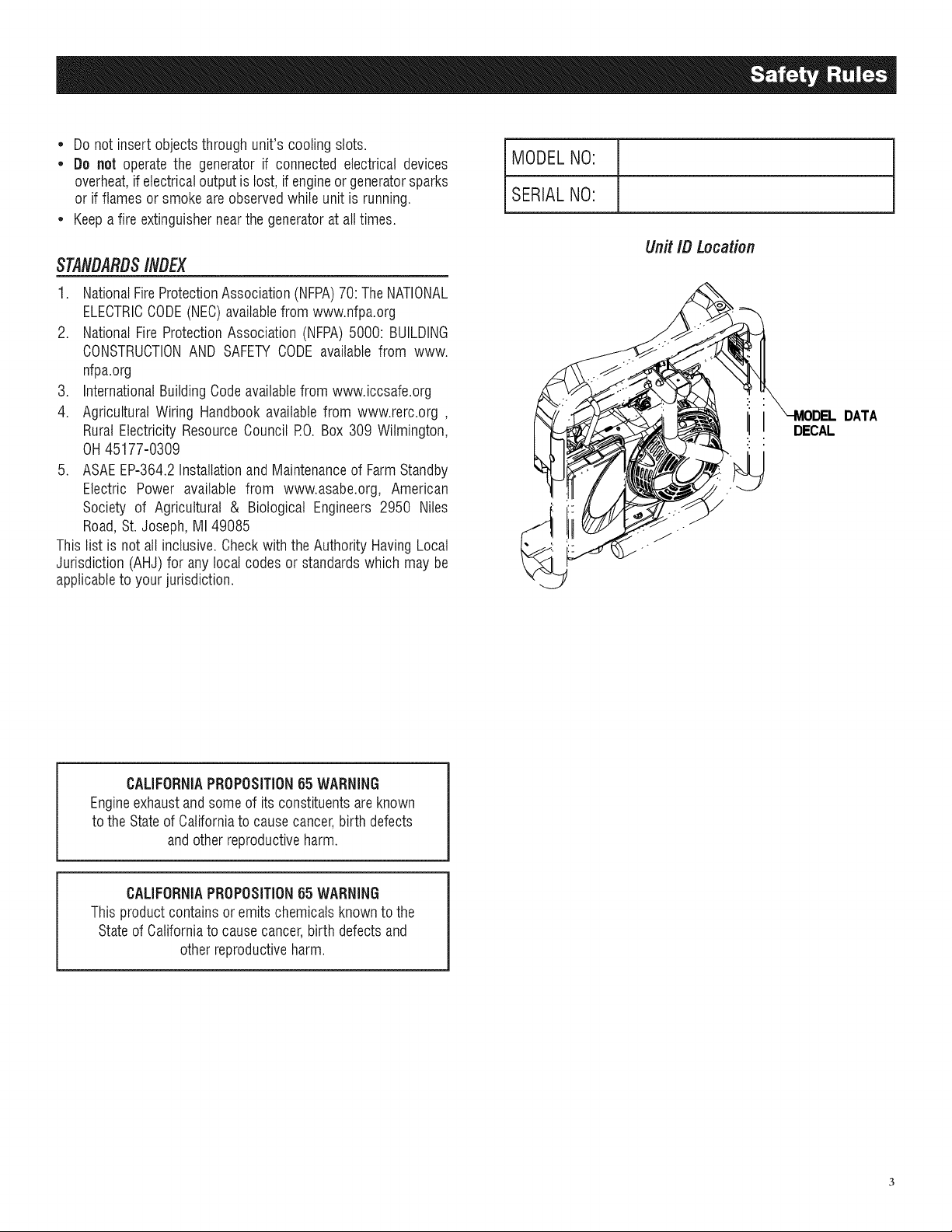
MODELNO:
SERIALNO:
Unit ID Location
I
I
DECAL
DATA
CALIFORNIAPROPOSITION65 WARNING
Engineexhaustandsomeof its constituentsareknown
to theStateof Californiato causecancer,birth defects
andotherreproductiveharm.
CALIFORNIAPROPOSITION65 WARNING
This productcontainsor emitschemicalsknown tothe
Stateof Californiato causecancer,birth defectsand
otherreproductiveharm.
1.1 UNPACKING
• Removeall packagingmaterial.
• Removeseparateaccessorybox.
• Removethegeneratorfrom carton.
1.1.1 ACCESSORYBOX
• 1-Owner's manual
• 1-Bottleof OilSAE30
• 3-ProductRegistrationCards (English,Spanish,French)
• 1-BatteryCharger(electricstart only)
• 1-HandleAssembly
• 1-FrameFoot(E)
• 2-Never-FlatWheels(H)
• 1-Hardwarebag(containingthefollowing):
- 2-LongCurvedHeadBolts(A)
- 2-AcornNuts(B)
- 4-Flangednuts(C)
- 2-RubberFeet(D)
- 2-ShortBolts(F)
- 2-AxlePins(G)
- 2-Washers(1)
- 2-CotterPins(J)
- 2-FlangeNuts(electricstartonly)
1.2 ASSEMBLY
The generator requires some assembly prior to using it. If
problems arise when assemblingthe generator,please call the
GeneratorHetplineat 1-888-436-3722.
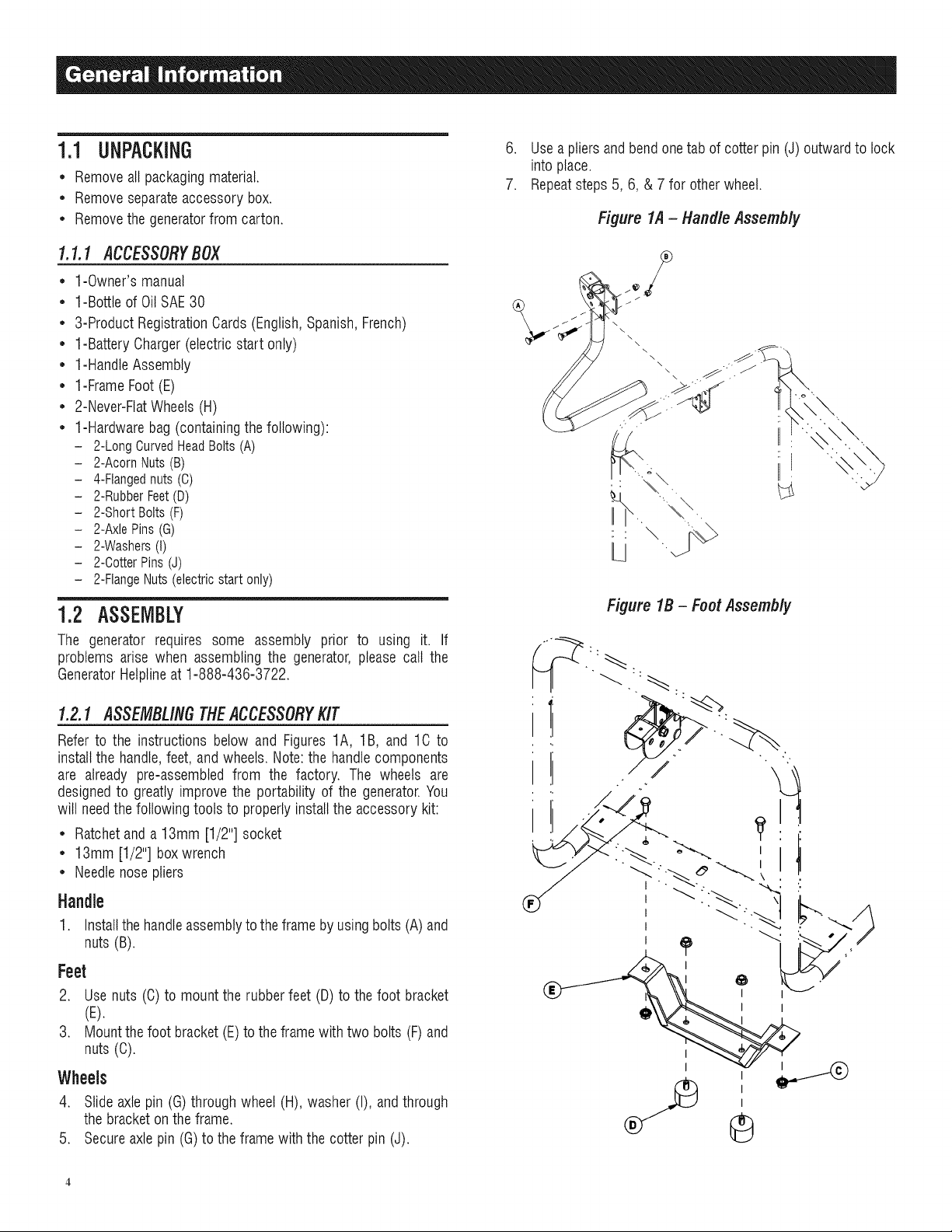
6. Usea pliersandbendonetab of cotterpin (J)outwardto lock
into place.
7. Repeatsteps5, 6, & 7 for other wheel.
Figure 1A- Handle Assembly
Figure 1B - Foot Assembly
1.2.1 ASSEMBLINGTHEACCESSORYKIT
Refer to the instructions below and Figures 1A, 1B, and 1C to
installthe handle,feet, and wheels. Note:the handlecomponents
are already pre-assembledfrom the factory. The wheels are
designedto greatly improve the portability of the generator.You
will needthefollowing tools to properlyinstallthe accessorykit:
• Ratchetanda 13mm [1/2"] socket
• 13mm [1/2"] boxwrench
• Needlenosepliers
Handle
1. Installthe handleassemblyto theframeby usingbolts (A) and
nuts (B).
Feet
2. Use nuts (C) to mount the rubberfeet (D)to the foot bracket
(E).
3. Mountthefoot bracket(E)to the framewith two bolts (F) and
nuts (C).
Wheels
4. Slideaxlepin (G)through wheel(H), washer (I), andthrough
thebracket on the frame.
5. Secureaxle pin (G)to the frame with the cotterpin (J).
I
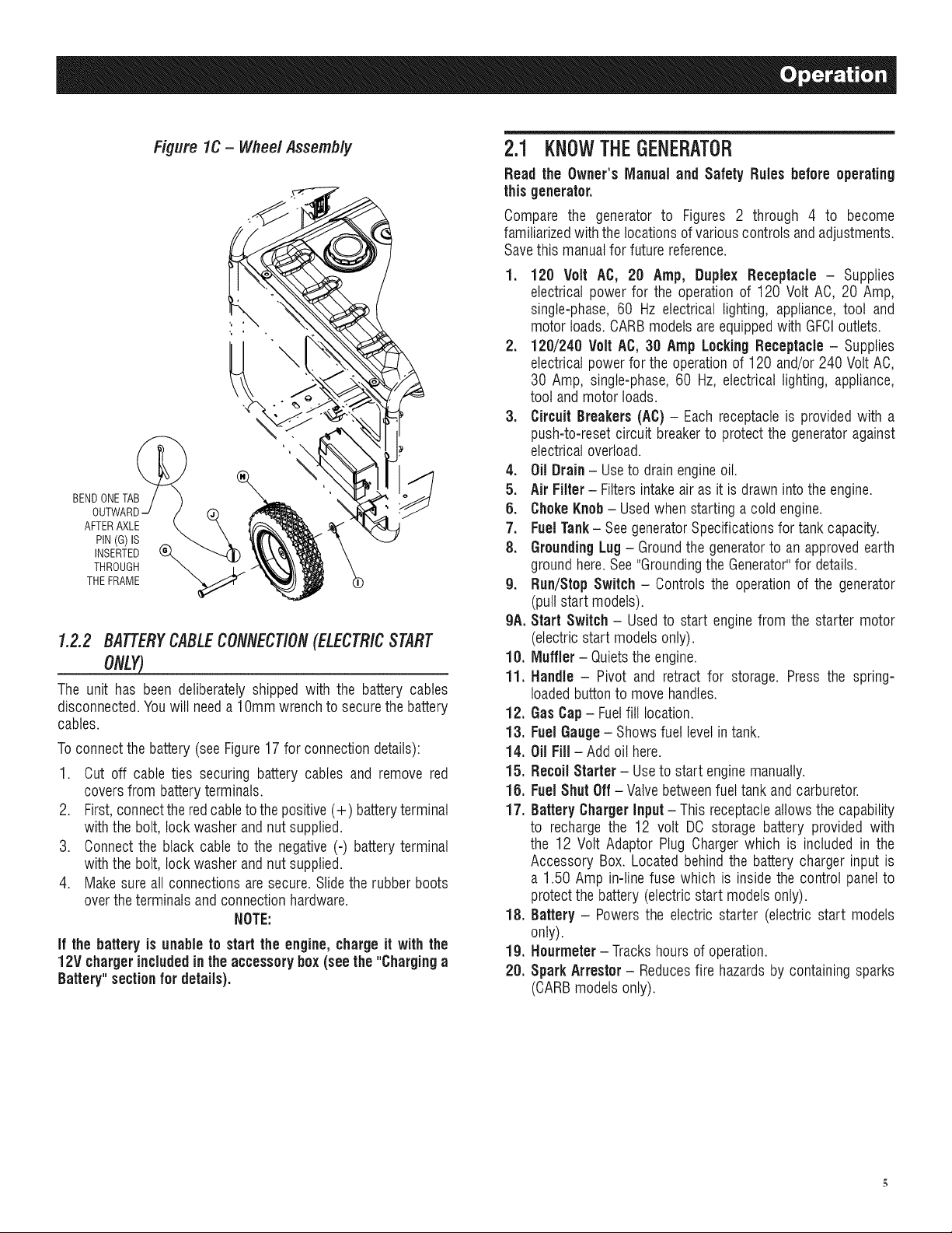
Figure lC - Wheel Assembly
BEND ONETAB
AFTERAXLE
PIN(G)IS
THROUGH
THEFRAME
INSERTED _
1.2.2 BATTERYCABLECONNECTION(ELECTRICSTART
ONLY)
The unit has been deliberately shipped with the battery cables
disconnected.Youwill needa lOmm wrenchto securethe battery
cables.
Toconnect the battery(seeFigure17 for connectiondetails):
1. Cut off cable ties securing battery cables and remove red
coversfrom batteryterminals.
2. First,connectthe redcableto the positive(+) batteryterminal
with the bolt, lock washer andnut supplied.
3. Connectthe black cable to the negative(-) batteryterminal
with the bolt, lock washer andnut supplied.
4. Make sureall connectionsare secure. Slidethe rubber boots
overthe terminalsand connectionhardware.
NOTE:
if the battery is unable to start the engine,charge it with the
12V chargerincludedinthe accessory box (seethe "Charginga
Battery"sectionfor details).
2.1 KNOWTHEGENERATOR
Read the Owner'sManual and Safety Rules before operating
this generator.
Compare the generator to Figures 2 through 4 to become
familiarizedwiththe locationsofvariouscontrols andadjustments.
Savethis manualfor future reference.
1. 120 Volt AC, 20 Amp, Duplex Receptacle - Supplies
electrical power for the operationof 120 Volt AC, 20 Amp,
single-phase,60 Hz electrical lighting, appliance, tool and
motor loads. CARBmodels areequippedwith GFCIoutlets.
2. 120/240 Volt AC, 30 Amp LockingReceptacle - Supplies
electricalpower for the operationof 120 and/or 240 VoltAC,
30 Amp, single-phase,60 Hz, electrical lighting, appliance,
tool andmotor loads.
3. Circuit Breakers(AC)- Eachreceptacleis provided with a
push-to-reset circuit breakerto protectthe generatoragainst
electricaloverload.
4. Oil Drain- Useto drainengineoil.
5. Air Filter- Filters intakeair as it is drawn intothe engine.
6. ChokeKnob- Usedwhen startinga cold engine.
7. FuelTank- SeegeneratorSpecificationsfor tank capacity.
8. GroundingLug - Groundthe generatorto an approvedearth
groundhere.See"Groundingthe Generator"for details.
g. Run/Stop Switch - Controls the operationof the generator
(pullstart models).
gA. Start Switch - Usedto start engine from the starter motor
(electricstart modelsonly).
10. Muffler - Quietsthe engine.
11. Handle - Pivot and retract for storage. Press the spring-
loadedbuttonto move handles.
12. GasCap- Fuelfill location.
13. FuelGauge- Showsfuel levelin tank.
14. Oil Fill- Addoil here.
15. Recoil Starter - Useto start enginemanually.
15. FuelShut Off - Valve betweenfueltank and carburetor.
17. BatteryCharger Input -This receptacleallowsthe capability
to recharge the 12 volt DO storage battery provided with
the 12 Volt Adaptor Plug Chargerwhich is included in the
Accessory Box. Located behindthe battery chargerinput is
a 1.50 Amp in-line fuse which is insidethe control panelto
protectthe battery (electricstart models only).
18. Battery - Powersthe electric starter (electric start models
only).
lg. Hourmeter- Trackshoursof operation.
28. Spark Arrestor - Reducesfire hazardsby containing sparks
(CARBmodels only).
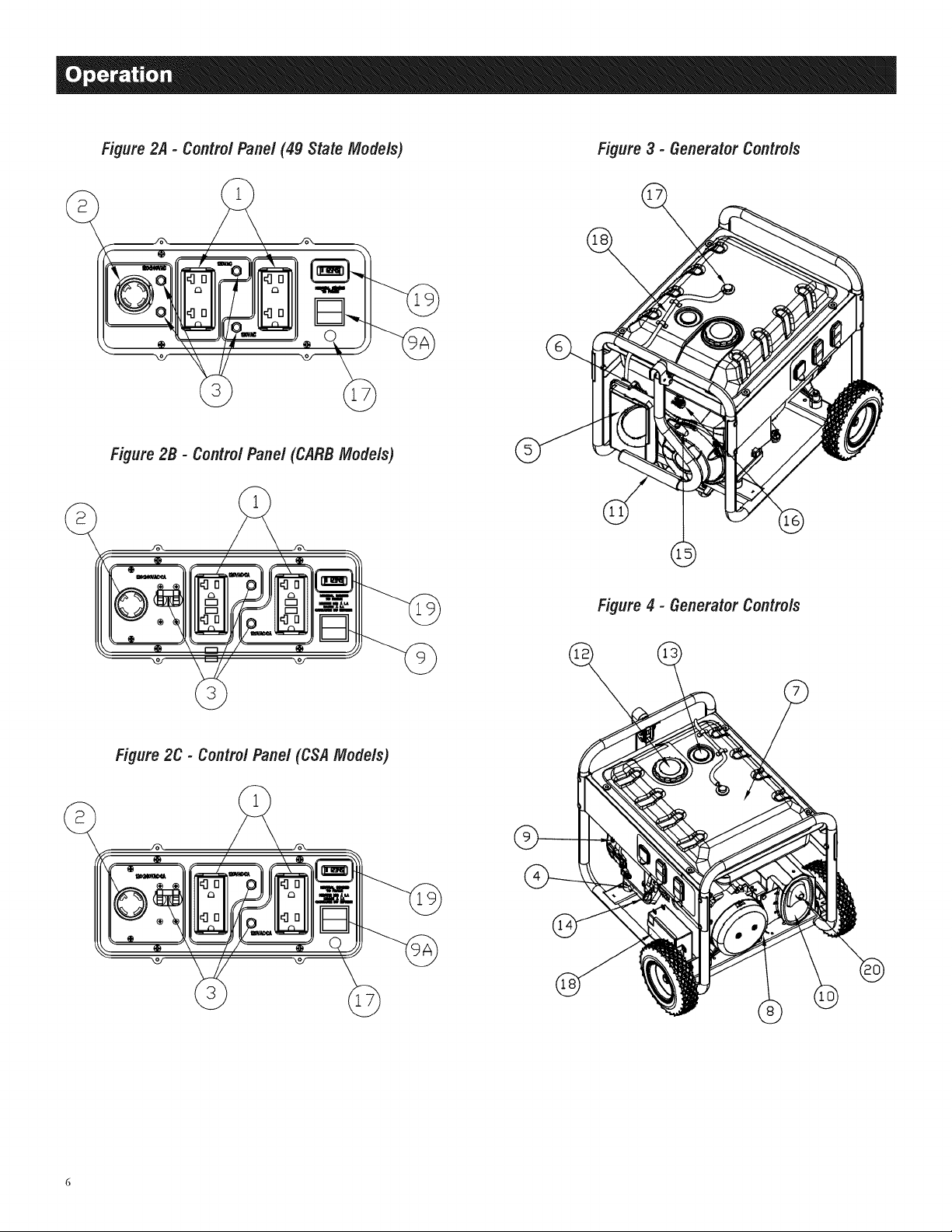
Figure2,4- Contro/Pane/(4g StateModels) Figure3 - Generator Controls
Figure2B - Contro/Panel (CARBModels)
Figure 2C - Contro/ Panel(CSAModels)
Figure4 - GeneratorControls

2.2 HOURIVIETER
TheHourmetertrackshoursofoperationfor scheduledmaintenance
(Figure5):
Therewill be a "CHGOIL"messageevery100 hours.Themessage
will flash one hour before and one hour after each 100 hour
interval,providing atwo hourwindow to perform service.
This messagewill actuallybeginflashing at 99 hoursand disable
itselfat 101 hoursagain,providingatwo hourwindow to perform
the service.
Every200 hours the "SVC"icon on the lower left hand corner of
the display will flash. Themessagewill flash one hourbefore and
onehourafter each200 hourintervalprovidingatwo hourwindow
to perform service.
Whenthe hour meter is inthe FlashAlert mode, the maintenance
message will always alternate with elapsed time in hours and
tenths. The hours wilt flash four times, then alternate with the
maintenancemessagefour timesuntil the meter resets itself.
• 100 hours- CHGOIL-- Oil ChangeInterval(Every100 hrs)
• 200 hours- SVC-- ServiceAir Filter(Every200 hrs)
Note:
The hour glassgraphicwill flash on and off when the engine
is running.This signifiesthat the meter is tracking hours of
operation.
Figure 6 - 120 Volt AC, 20 Amp, Duplex Receptacle
D
2.3.2 120/240VAC,30 AMPRECEPTACLE
Use a NEMA L14-30 plug with this receptacle (rotate to lock!
unlock). Connecta suitable4-wire groundedcord set to the plug
andto thedesiredtoad.Thecord set should be ratedfor 250 Volts
ACat 30 Amps (or greater)(Figure7).
Figure 7 - 120/240 VAC,30 Amp Receptacle
Figure 5 - Hourmeter
0000.0
,
HOURGLASS RESETBUTTON
GRAPHIC (IF EQUIPPED)
2.3 CORDSETSANDCONNECTIONPLUGS
2.3.1 120VAC,20 AMP,DUPLEXRECEPTACLE
This is a 120 Volt outlet protectedagainstoverloadby a 20 Amp
push-to-resetcircuitbreaker (Figure6). Useeach socketto power
120 VoltAC, singlephase,60 Hzelectrical loadsrequiringupto a
combined 2400 watts (2.4 kW) or 20 Ampsof current. Useonly
high quality, well-insulated, 3-wire grounded cord sets ratedfor
125 Volts at 20 Amps (or greater).
Keep extensioncords as short as possible, preferablyless than
15 feet long, to preventvoltage drop and possibleoverheatingof
wires.
12OV/24OV
3CA
Use this receptacleto operate 120 Volt AC, 60 Hz, single phase
loadsrequiringup to 3600 watts (3.6kW) of power at30 Amps or
240 VoltAC,60 Hz, singlephaseloadsrequiringup to 7200 watts
(7.2 kW) of power at 30 Amps. The outlet is protectedby two 30
Amp push-to-resetcircuit breakers.
2.3.3 120VAC,20AMP,GFC/OUPLEXRECEPTACLE
This is a 120 Volt outlet protectedagainstoverloadby a 20 Amp
push-to=resetcircuit breaker(Figure8). Useeachsocketto power
120 VoltAC, singlephase,60 Hzelectrical loadsrequiringup to a
combined 2400 watts (2.4 kW) or 20 Ampsof current.Use only
high quality, well-insulated, 3-wire grounded cord sets ratedfor
125 Volts at 20 Amps (or greater).
Keepextensioncords as short as possibleto preventvoltagedrop
and possibleoverheatingof wires.
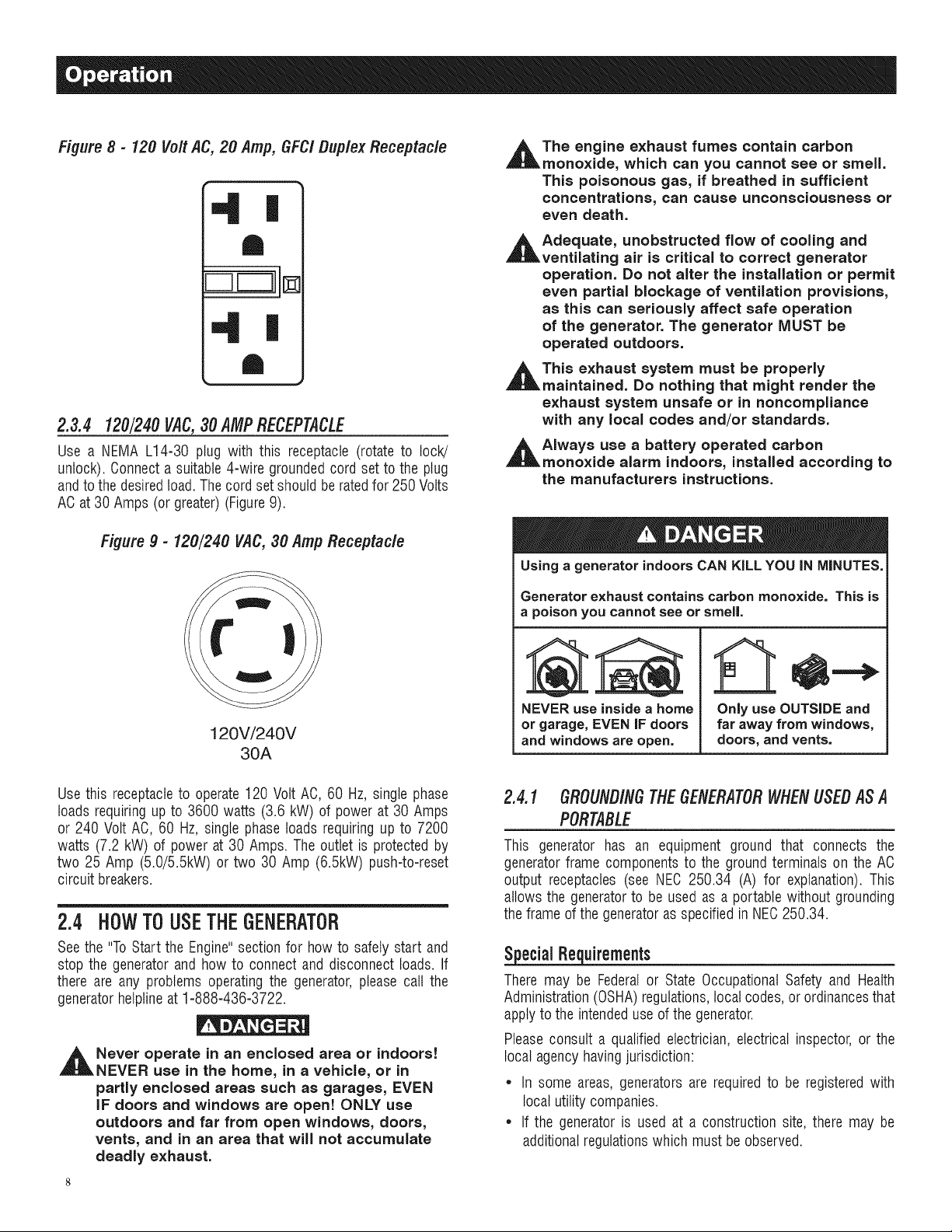
Figure 8 - 120 Vo/t AC, 20 Amp, GFC/ Duplex Receptac/e
2.3.4 120/240VAC,30 AMPRECEPTACLE
Use a NEMA L14-30 plug with this receptacle (rotate to lock!
unlock). Connecta suitable4-wire groundedcord set to the plug
andto thedesiredtoad.Thecord set should be ratedfor 250 Volts
ACat 30 Amps (or greater)(Figure9).
Figure 9 - 120/240 VAC,30 Amp Receptac/e
_t he engine exhaust fumes contain carbon
monoxide, which can you cannot see or smell.
This poisonous gas, if breathed in sufficient
concentrations, can cause unconsciousness Or
even death.
_t Adequate, unobstructed flow of cooling and
ventilating air is critical to correct generator
operation. Do not alter the installation or permit
even partial blockage of ventilation provisions,
as this can seriously affect safe operation
of the generator. The generator MUST be
operated outdoors.
_t This exhaust system must be properly
maintained. Do nothing that might render the
exhaust system unsafe or in noncompliance
with any local codes and/or standards.
_t Always use a battery operated carbon
monoxide alarm indoors, installed according to
the manufacturers instructions.
Using a generator indoors CAN KiLL YOU iN MINUTES.
Generator exhaust contains carbon monoxide. This is
a poison you cannot see or smell.
12OV/24OV
3CA
Use this receptacleto operate120 Volt AC, 60 Hz, single phase
loads requiringup to 3600 watts (3.6 kW) of powerat 30 Amps
or 240 Volt AC, 60 Hz,single phase loads requiringup to 7200
watts (7.2 kW) of power at 30 Amps. The outlet is protectedby
two 25 Amp (5.0/5.5kW) or two 30 Amp (6.5kW) push-to-reset
circuit breakers.
2.4 H0WTOUSETHEGENERATOR
Seethe "ToStart the Engine"sectionfor howto safelystart and
stop the generator and how to connect and disconnect loads. If
there are any problems operatingthe generator,please call the
generatorhelplineat 1-888-436-3722.
_t ever operate in an enclosed area or indoors!
NEVER use in the home, in a vehicle, or in
partly enclosed areas such as garages, EVEN
IF doors and windows are open! ONLY use
outdoors and far from open windows, doors,
vents, and in an area that will not accumulate
deadly exhaust.
NEVER use inside a home
or garage, EVEN iF doors
and windows are open.
Only use OUTSIDE and
far away from windows,
doors, and vents.
2.4.1 GROUNDINGTHEGENERATORWHENUSEDASA
PORTABLE
This generator has an equipment ground that connects the
generatorframe componentsto the ground terminals on the AC
output receptacles (see NEC 250.34 (A) for explanation). This
allows the generatorto be used as a portablewithout grounding
theframe ofthe generatoras specifiedin NEC250.34.
SpecialRequirements
There may be Federalor State OccupationalSafety and Health
Administration(OSHA)regulations,localcodes, or ordinancesthat
applyto the intendeduse ofthe generator.
Pleaseconsult a qualified electrician, electrical inspector, or the
local agencyhavingjurisdiction:
* In some areas, generators are requiredto be registeredwith
local utilitycompanies.
* If the generatoris used at a construction site, there may be
additionalregulationswhich must be observed.
2.4.2 CONNECT/NGTHEGENERATORTOA BU/LD/NG'$
ELECTR/CALSYSTEM
Connectionsfor standby power to a building's electricalsystem
must be made by a qualifiedelectricianand in strict compliance
with all national and local electrical codes and laws. The
connectionmust isolatethe generatorpowerfrom utility poweror
otheralternativepowersources.
NOTE:
Because the generatorequipmentground is bonded to the AC
neutral wires in the generator(see Figure 8), either a 3-pole
transferswitch or a 2 pole transferswitch with a switching
neutral kit is requiredto connectthis generatorto a building
load. in this application the generator becomes a separately
derived system(see NEC250.20 (D)), and mustbe grounded
in accordance with the national or local electrical code
requirements.
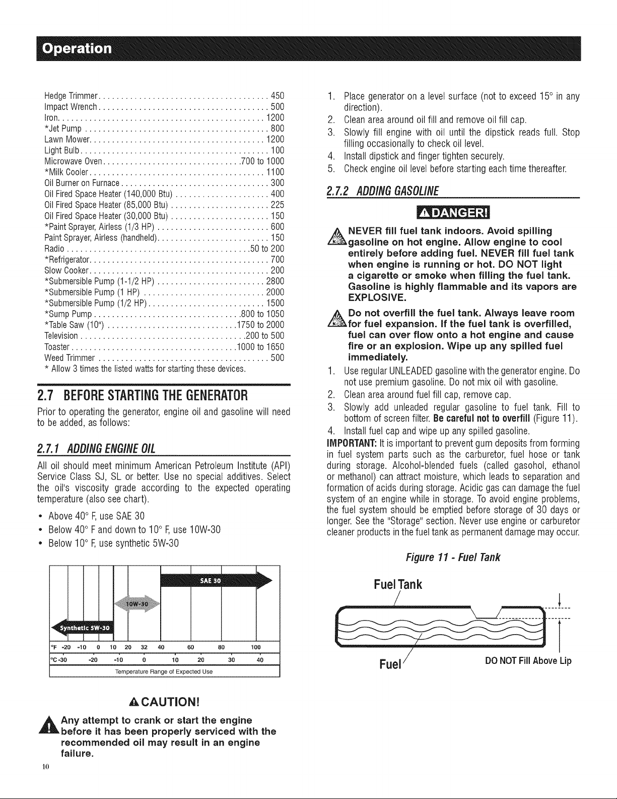
GroundingtheGeneratorina BuildingStandbyApplication
_ he National Electrical Code requires that the
frame and external electrically conductive parts
of this generator be properly connected to an
approved earth ground.
Local electrical codes may also require proper grounding of the
unit (Figure 10). For that purpose, connecting a No. 10 AWG
(AmericanWire Gauge)strandedcopperwire to the groundinglug
and to an earth=drivencopperor brass groundingrod (electrode)
provides adequateprotection against electrical shock. However,
local codes mayvary widely.Consultwith a local electrician for
grounding requirementsinthe area.
Proper groundingof the generator will help preventelectrical
shockintheeventof a groundfault condition inthe generatoror in
connectedelectricaldevices.Propergroundingalsohelpsdissipate
static electricity,which often buildsup in ungroundeddevices.
Figure 10- Grounding the Generator
2.5 DON'TOVEBLOADTHEGENEBATOB
Overloadinga generatorin excess of its rated wattage capacity
can result in damageto the generatorand to connectedelectrical
devices.Observethefollowing to preventoverloadingthe unit:
* Addupthe total wattageofall electricaldevicesto beconnected
at one time. This total should NOT be greater than the
generator'swattagecapacity.
* Theratedwattage of lights can betaken from light bulbs. The
ratedwattage of tools, appliancesand motors can usually be
found on a data labelor decalaffixedto the device.
* Ifthe appliance,toot or motor does not give wattage,multiply
voltstimes ampereratingto determinewatts (volts x amps =
watts).
* Someelectric motors, such as induction types, requireabout
threetimes more watts of powerfor startingthan for running.
This surge of power lasts only a few seconds when starting
suchmotors. Makesureto allowfor high startingwattagewhen
selectingelectrical devicesto connect to the generator:
1. Figurethe watts neededto start the largestmotor.
2. Add to that figure the running watts of all other connected
loads.
TheWattageReferenceGuideis providedto assist in determining
how many itemsthegeneratorcanoperateat onetime.
NOTE:
All figures are approximate.See data label onappliancefor
wattage requirements.
2.6 WATTAGEBEFEBENCEGUIDE
Device ................................... RunningWatts
*Air Conditioner (12,000 Btu).......................... 1700
*Air Conditioner (24,000 Btu).......................... 3800
*Air Conditioner (40,000 Btu).......................... 6000
BatteryCharger(20 Amp).............................. 500
BeltSander(3") .................................... 1000
ChainSaw ........................................ 1200
CircularSaw (6-1/2") ........................... 800 to 1000
*Clothes Dryer (Electric) ............................. 5750
*Clothes Dryer (Gas) ................................. 700
*Clothes Washer ................................... 1150
CoffeeMaker ...................................... 1750
*Compressor (1 HP)................................. 2000
*Compressor (3/4 HP)............................... 1800
*Compressor (1/2 HP)............................... 1400
CurlingIron......................................... 700
*Dehumidifier....................................... 650
DiscSander(9").................................... 1200
EdgeTrimmer....................................... 500
Electric Blanket...................................... 400
Electric NailGun.................................... 1200
Electric Range(per element)........................... 1500
ElectricSkillet...................................... 1250
*Freezer............................................ 700
*FurnaceFan (3/5 HP) ................................ 875
*GarageDoor Opener............................ 500 to 750
HairDryer......................................... 1200
HandDrill .................................... 250 to 1100
HedgeTrimmer...................................... 450
ImpactWrench...................................... 500
Iron.............................................. 1200
*JetPump......................................... 800
LawnMower....................................... 1200
LightBulb.......................................... 100
MicrowaveOven............................... 700to1000
*MilkCooler....................................... 1100
OilBurneronFurnace................................. 300
OilFiredSpaceHeater(140,000Btu)..................... 400
OilFiredSpaceHeater(85,000Btu)...................... 225
OilFiredSpaceHeater(30,000Btu)...................... 150
*PaintSprayer,Airless(1/3HP)......................... 600
PaintSprayer,Airless(handheld)......................... 150
Radio......................................... 50to200
*Refrigerator........................................ 700
SlowCooker........................................ 200
*SubmersiblePump(1-1/2HP)........................ 2800
*SubmersiblePump(1HP)........................... 2000
*SubmersiblePump(1/2HP).......................... 1500
*SumpPump................................. 800to1050
*TableSaw(10")............................. 1750to2000
Television..................................... 200to500
Toaster..................................... 1000to1650
WeedTrimmer...................................... 500
*Allow3timesthelistedwattsforstartingthesedevices.
2.7 BEFORESTARTIN6THEGENERATOR
Priorto operatingthe generator,engineoil and gasolinewill need
to be added,asfollows:
2.7.1 AL}gitVGEtVGIflEO/L
All oil should meet minimum American PetroleumInstitute (API)
Service Class SJ, SL or better.Use no special additives. Select
the oil's viscosity grade according to the expected operating
temperature(also see chart).
* Above40° F,useSAE30
* Below40° Fand downto 10° F,use10W-30
* Below10° F,usesynthetic 5W-30
1. Placegeneratoron a levelsurface (not to exceed15° in any
direction).
2. Cleanareaaroundoil fill andremoveoil fill cap.
3. Slowly fill engine with oil until the dipstick readsfull. Stop
filling occasionallyto checkoil level.
4. Installdipstick andfingertighten securely.
5. Checkengineoil levelbefore starting eachtimethereafter.
2.7.2 ADD/NGGASOLINE
NEVER fill fuel tank indoors. Avoid spilling
gasoline on hot engine. Allow engine to cool
entirely before adding fuel. NEVER fill fuel tank
when engine is running or hot. DO NOT light
a cigarette or smoke when filling the fuel tank.
Gasoline is highly flammable and its vapors are
EXPLOSIVE.
Do not overfill the fuel tank. Always leave room
for fuel expansion. If the fuel tank is overfilled,
fuel can over flow onto a hot engine and cause
fire or an explosion. Wipe up any spilled fuel
immediately.
1. UseregularUNLEADEDgasolinewiththegeneratorengine.Do
not usepremiumgasoline.Do not mix oilwith gasoline.
2. Cleanareaaroundfuel fill cap, removecap.
3. Slowly add unleaded regular gasoline to fuel tank. Fill to
bottom of screenfilter. Be carefulnottooverfill (Figure11).
4. Installfuel cap andwipe up any spilled gasoline.
IMPORTANT:Itis importantto preventgum depositsfrom forming
in fuel system parts such as the carburetor,fuel hose or tank
during storage. Alcohol-blended fuels (called gasohol, ethanol
or methanol)can attract moisture, which leadsto separationand
formationof acids duringstorage.Acidic gascan damagethefuel
system of an enginewhile in storage.Toavoid engineproblems,
the fuel system should be emptiedbefore storage of 30 days or
longer.Seethe "Storage"section. Neveruseengineor carburetor
cleanerproducts inthefueltank aspermanentdamagemay occur.
Figure 11 - Fuel Tank
mEm
°F -20 -10 0 10 20 32 40 60 80 100
oc-3'o -_o -lo o lo 2'0 3'o 4b
Temperature Range of Expected Use
_CAUTION!
Any attempt to crank or start the engine
before it has been properly serviced with the
recommended oil may result in an engine
failure.
1o
FueJTank
T
Fuel/ Do NOTFillAboveLip
2.8 STARTINGPULLSTARTENGINES
Never start or stop engine with electrical
devices plugged into the receptacles AND
devices turned on.
1. Unplugall electrical loadsfrom the unit's receptaclesbefore
startingthe engine.
2. Make surethe unitis in a levelposition (notto exceed15° in
anydirection).
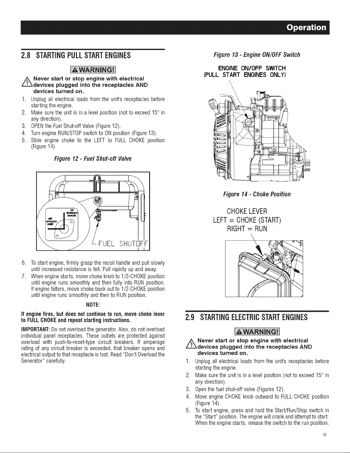
3. OPENthe FuelShut-offValve(Figure12).
4. TurnengineRUN/STOPswitch to ONposition (Figure13).
5. Slide engine choke to the LEFT to FULL CHOKEposition
(Figure14).
Figure 13 - Engine ON/OFF Switch
ENGINE ON/OFF SWITCH
(PULL START ENGINES ONLY)
\
Figure 12- FuelShut-off Valve
FUEL SHUTOFF
.
Tostart engine,firmly graspthe recoil handleandpull slowly
until increasedresistanceisfelt. Pullrapidly up and away.
7.
Whenenginestarts, move chokeknob to 1/2-CHOKEposition
until engine runs smoothly andthen fully into RUN position.
If enginefalters,move chokeback outto 1/2-CHOKEposition
untilengine runssmoothly andthento RUNposition.
NOTE:
if enginefires, but does not continueto run,move chokelever
to FULLCHOKEand repeatstarting instructions.
IMPORTANT:Donotoverloadthe generator.Also, do not overload
individual panel receptacles.Theseoutlets are protected against
overload with push-to-reset-type circuit breakers. If amperage
rating of any circuit breakeris exceeded,that breaker opensand
electricaloutputto that receptacleislost. Read"Don't Overloadthe
Generator"carefully.
lllh
Figure 14 - Choke Position
CHOKELEVER
LEFT= CHOKE(START)
RIGHT= RUN
2.9 STARTINGELECTRICSTARTENGINES
Never start or stop engine with electrical
devices plugged into the receptacles AND
devices turned on.
1. Unplugall electricalloads from the unit's receptaclesbefore
startingthe engine.
2. Makesurethe unit is in a level position (not to exceed15° in
anydirection).
3. Openthefuel shut-off valve (Figures12).
4. Move engineCHOKEknoboutward to FULLCHOKEposition
(Figure14).
5. Tostart engine, press and hold the Start/Run/Stopswitch in
the"Start" position. Theenginewill crankandattemptto start.
Whenthe enginestarts, releasethe switchto the run position.
11
.
Whenthe engine starts, move choke knob to "1/2 Choke"
position untilthe engineruns smoothly andthen fully into the
"Run" position.If enginefalters,move chokeknob backoutto
"1/2 Choke"position untilthe engineruns smoothly andthen
to "Run" position.
2.9.1 MANUALSTART
Thisgeneratoris also equippedwith amanualrecoil starterwhich
may be used if the batteryis discharged.
NOTE:
The switch must be in the RUN position. Use one of the
generator's receptacle outletsalong with the includedbattery
chargerto chargethe battery while the generator is running.
Tostart manually,firmly graspthe recoil handleand pull slowly
until increasedresistanceis felt. Pull rapidly up and away to
start engine.Thenfollow the same choke sequence.
NOTE:
If enginefires, but does not continueto run, move chokelever
to FULLCHOKEand repeatstarting instructions.
IMPORTANT:Donot overloadthe generator.Also, do not overload
individual panel receptacles.Theseoutlets are protected against
overload with push-to-reset-type circuit breakers. If amperage
ratingof any circuit breaker is exceeded,that breakeropens and
electricaloutputto that receptacleislost. Read"Don't Overloadthe
Generator"carefully.
2.12 CHARGINGTHEBATTERY(ELECTRICSTART
UNITSONLY)
Storage batteries give off explosive hydrogen
gas while recharging. An explosive mixture will
remain around the battery for a long time after
it has been charged. The slightest spark can
ignite the hydrogen and cause an explosion.
Such an explosion can shatter the battery and
cause blindness or other serious injury.
_tDo not permit smoking, flame, sparks
or any other source of heat around a battery.
Wear protective goggles, rubber apron and
rubber gloves when working around a battery.
Battery electrolyte fluid is an extremely
corrosive sulfuric acid solution that can cause
severe burns, if spill occurs flush area with
clear water immediately.
The battery shipped withthe generator hasbeen fully charged.
A battery may lose some of its chargewhen not in use for
prolongedperiodsof time. If the battery is unable to crankthe
engine,plugin the12V chargerincludedin the accessory box.
RUNNINGTHEGENERATORDOESNOTCHARGETHEBATTERY.
open
NOTE:
2.10STOPPINGTHEENGINE
1. Shut off all loads, then unplug the electrical loads from
generatorpanel receptacles.Never start or stop the engine
with electricaldevicespluggedin andturnedon.
2. Let enginerun at no-load for severalminutesto stabilizethe
internaltemperaturesof engineandgenerator.
3. Move Run/Stopswitch to OFFposition.
4. Closefuelvalve.
2.11LOW01LLEVELSHUTDOWNSYSTEM
Theengineis equippedwith a low oil levelsensorthat shuts down
the engineautomaticallywhenthe oil leveldropsbelowa specified
level. If the engine shuts down by itself and the fuel tank has
enoughgasoline,check engineoil level.
2.11.1 SENSINGLOWOILLEVEL
If the system senses a low oil level during operation,the engine
shuts down. Theenginewill not run until the oil has beenrefilled
to the proper level.
Usebatterychargerplugto keepthe batterychargedandreadyfor
use. Batterychargingshouldbe done in a dry location.
1. Plugchargerinto "BatteryChargerInput" jack, locatedon the
control panel.Plugwall receptacleendof the battery charger
into a 120 Volt ACwall outlet.
2. Unplugbattery chargerfromwall outletand control paneljack
whengeneratoris goingto be in use.
NOTE:
Do not use the battery chargerfor more than 48 hoursat one
charge.
Figure 15 - Battery Charger Jack
BATTERY
CHARGER
INPUT
12
3.1 PERFORMINGSCHEDULEDMAINTENANCE
It is important to perform serviceas specifiedin the Maintenance
Schedulefor proper generator operation,and to ensurethat the
generatorcomplies with the applicableemissionstandardsfor the
durationof its useful life.Serviceandrepairsmaybe performedby
any capableperson or repairshop.Additionally,emissionscritical
maintenancemust be performed as scheduled in order for the
Emissions Warrantyto be valid. Emissions critical maintenance
consists of servicing the air filter and spark plugs in accordance
with the MaintenanceSchedule.
3.2 MAINTENANCESCHEDULE
Follow the calendar intervals. More frequent service is required
whenoperatingin adverseconditions notedbelow.
CheckOil Level
ChangeOil
*Every 100 hoursor EverySeason
CheckValveClearance
ServiceAir Filter
** Every200 hoursor EverySeason
ReplaceSparkPlug
:i: Changeoil after first 30 hours of operationthenevery season.
* Changeoiland oilfilter everymonth whenoperatingunderheavy load or in high
temperatures.
** Clean more often under dirty or dusty operating conditions. Replaceair filter
parts ifthey cannot beadequatelycleaned.
*** Check valve clearance and adjust if necessary after first 50 hours of
operationand every 100 hours thereafter.
At EachUse
***Every Season
EverySeason
3.3 PRODUCTSPECIFICATIONS
3.3.1 GENERATORSPEC/F/CATiONS
RatedPower............................................................... 5.0/5.5/6.5 kW**
SurgePower............................................................... 6.25/6.88/8.0 kW
RatedACVoltage...................................................................... 120/240
RatedAC Load
Current@ 240V (5.0/5.5/6.5 kW) ..................20.8/22.9/27.1 Amps**
Current@ 120V (5.0/5.5/6.5 kW) ..................41.6/45.8/54.2 Amps**
RatedFrequency.................................................... 60 Hz@ 3600 RPM
Phase................................................................................ SinglePhase
** Maximumwattageandcurrentaresubjectto,andlimitedby,suchfactors
asfuelBtucontent,ambienttemperature,altitude,enginecondition,etc..
Maximumpowerdecreasesabout3.5%foreach1,000feetabovesealevel;
andwillalsodecreaseabout1%foreach6° C (10° F)above16° C(60° F)
ambienttemperature.
3.3.3 EM/SS/ONS/NFORIVIAT/ON
TheEnvironmentalProtectionAgency(and CaliforniaAir Resource
Board for generators certified to CA standards) require(s)that
this generator comply with exhaust and evaporative emission
standards.Locate the emissions compliance decalon the engine
to determinewhat standards the generatormeets.This generator
is certified to operateon gasoline.The emission control system
includesthefollowing components(if equipped):
Air Induction System • Ignition System
- IntakePipe/ Manifold -- SparkPlug
- Air Cleaner -- IgnitionModule
Fuel System • Exhaust System
- Carburetor -- ExhaustManifold
- FuelTank/Cap -- Muffler
- FuelLines -- PulsedAir Valve
- EvaporativeVentLines -- Catalyst
- CarbonCanister
3.4 GENERALRECOMMENDATIONS
Thewarranty of thegeneratordoes notcover itemsthat havebeen
subjectedto operator abuseor negligence.To receivefull value
from the warranty, the operator must maintain the generatoras
instructed inthis manual.
Some adjustmentswilt need to be made periodically to properly
maintainthegenerator.
All adjustmentsin the Maintenancesectionof this manualshould
be madeat leastonce eachseason.Followthe requirementsinthe
"MaintenanceSchedule".
NOTE:
Once a year replace the spark plug and replace the air filter.
A new spark plug and clean air filter assure properfuel-air
mixture andhelpthe engine runbetter andlast longer.
3.4.1 GENERATORMAINTENANCE
Generatormaintenanceconsistsof keepingthe unit cleanand dry.
Operateandstorethe unit in a cleandry environmentwhereit will
not be exposedto excessivedust,dirt, moistureor any corrosive
vapors.Coolingair slotsin thegeneratormustnot becomeclogged
with snow, leaves,or anyotherforeign material.
Checkthe cleanlinessof the generatorfrequentlyand cleanwhen
dust, dirt, oil, moisture or otherforeign substancesarevisible on
its exteriorsurface.
3.3.2 ENGINESPECIFICATIONS
Displacement.............................................................................. 389 cc
SparkPlugType................................ NHSPLDF7TCor ChampionN9YC
SparkPlug Part No........................................................... 0G84420101
SparkPlug Gap.............................0.028-0.031 inch or (0.70-0.80 mm)
GasolineCapacity......................................................... 7.2 U.S. gallons
OilType.................. SeeChart in "Before Startingthe Generator"Section
OilCapacity.................................................................... 1 L (1.06 Qts.)
RunTimeat 50% Load (5.0/5.5/6.5 kW)..................................10 Hours
,ACAUTION!
,_ Never insert any object or tool through the air
cooling slots, even if the engine is not running.
NOTE:
DONOTuse a gardenhoseto cleangenerator. Water canenter
the enginefuel systemand causeproblems.In addition,if water
enters thegenerator throughcoolingair slots,some water will
be retainedin voidsand crevicesof therotorand stator winding
insulation.Water and dirt buildup on the generator internal
windingswill eventually decrease the insulationresistanceof
these windings.
13
3.4.2 TOCLEANTHEGENERATOR
• Usea damp cloth to wipe exteriorsurfaces clean.
• A soft, bristlebrush may be usedto loosen caked on dirt, oil,
etc.
• Avacuumcleanermay be usedto pick up loosedirt anddebris.
• Low pressure air (not to exceed 25 psi) may be used to
blow away dirt. Inspect cooling air slots and openings
on the generator.These openings must be kept clean and
unobstructed.
3.4.3 ENG/NEMA/NTENANCE
//_When working on the generator, always
disconnect negative cable from battery. Also
disconnect spark plug wire from spark plug and
keep wire away from spark plug.
3.4.4 CNECK/NGO/LLEVEL
Seethe "BeforeStartingthe Generator"sectionfor informationon
checkingthe oil level.Theoil levelshould be checkedbeforeeach
use, or at least every eight hours of operation. Keepthe oil level
maintained.
3.4.5 CNANG/NGTHEO/L
Changethe oil after the first 30 hours of operation. Changethe
oil every 100 hours or every season thereafter. If running this
unit underdirty or dusty conditions, or in extremelyhot weather,
changethe oil moreoften.
,A CAUTION!
,l_ Hot oil may cause burns. Allow engine to
cool before draining oil. Avoid prolonged
or repeated skin exposure with used oil.
Thoroughly wash exposed areas with soap.
Usethe followinginstructionsto changetheoil aftertheengine
coolsdown:
1. Cleanareaaroundoil drain plug.
2. Removeoil drain plugfrom engineandoil fill plugto drainoil
completely intoa suitablecontainer.
3. When oil has completely drained, install oil drain plug and
tighten securely.
4. Filloil sumpwith recommendedoil. (See"BeforeStartingthe
Generator"for oil recommendations).
5. Wipeup any spilledoil.
6. Disposeof used oil ata propercollectioncenter.
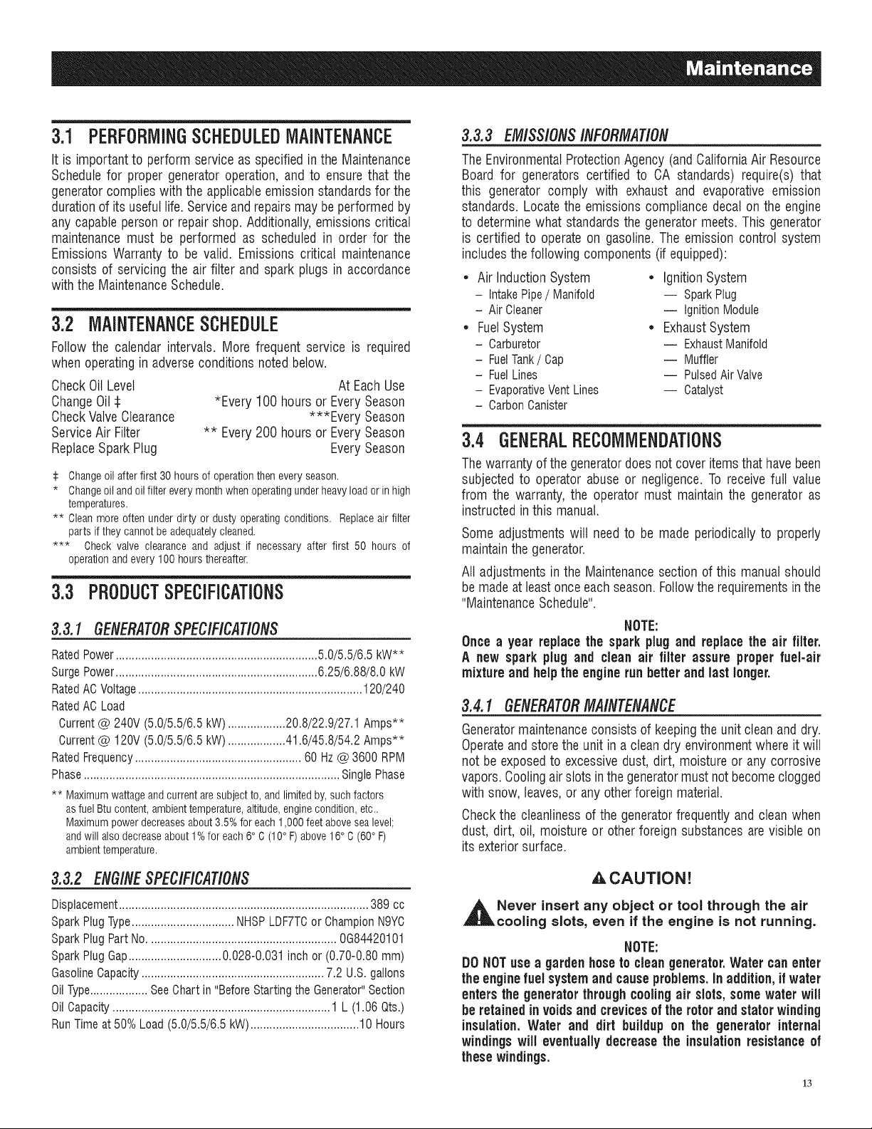
3.4.6 REPLACINGTHESPARKPLUG
SeeEngineSpecificationsfor recommendedspark plug.Replace
theplugonceeach year.This will helpthe enginestarteasierand
run better.
1. Stopthe engineand pull the spark plug wire off of the spark
plug.
2. Cleanthe areaaroundthe spark plug and remove itfrom the
cylinder head.
3. Setthe spark plug'sgapto 0.70-0.80 mm (0.028-0.031 in.).
Installthe correctly gappedspark plug intothe cylinder head
(Figure16).
Figure 16 - Spark Plug Gap
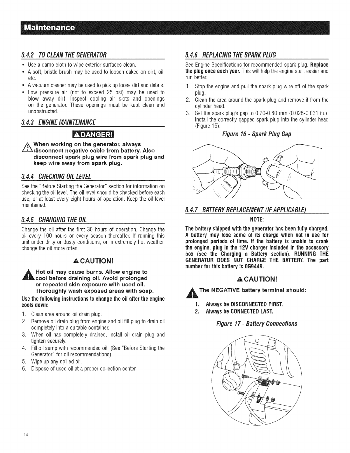
3.4.7 BATTERYREPLACEMENT{IFAPPLICABLE)_
NOTE:
Thebattery shippedwith the generator has been fully charged.
A battery may lose some of its chargewhen not in use for
prolongedperiodsof time. If the battery is unable to crank
the engine,plugin the 12V chargerincludedin the accessory
box (see the Charging a Battery section). RUNNINGTHE
GENERATORDOES NOT CHARGETHE BATTERY.The part
numberfor this batteryis 0G9449.
,_ CAUTION!
,l_The NEGATIVE battery terminal should:
1. Always be DISCONNECTEDFIRST.
2. Alwaysbe CONNECTEDLAST.
Figure17 - Battery Connections
14

3.5 SERVICEAiRCLEANER
The engine will not run properly and may be damagedif using
a dirty air cleaner.Clean or replacethe air cleaner paper filter
once a year.Cleanor replacemore often if operatingunder dusty
conditions(Figure18). Theair filter part numberis 0G84420151.
Tocleanor replacepaperair filter:
1. Removeair cleanercover andremove paperfilter.
2. Cleanpaperfilter bytapping it gently on a solid surface. If the
filter is too dirty, replaceit with a newone. Disposeof the old
filter properly.
3. Cleanair cleanercover, then insert new paper filter into the
baseof the air cleaner.Re-installair cleanercover.
Figure 18- Air Filter
Figure 19 - Spark Arrestor Screen
ARRESTDR
SPARK
ARRESTOR
SCREEN2
NOTE:
Toorder a newair filteror sparkarrestor screen,pleasecontact
the nearestauthorizedservice centerat 1-800-333-1322.
3.6 VALVECLEARANCE
* Intake-- 0.15 _ O.02mm(cold), (0.006" _ 0.0008" inches)
* Exhaust-- 0.20 _ O.02mm(cold) (0.008" _ 0.0008" inches)
After the first 50 hoursof operation, checkthe valve clearance
in the engineand adjustif necessary.
Important: If feelinguncomfortable aboutdoing this procedureor
the propertools are not available,pleasetakethe generatorto the
nearestservicecenterto havethevalveclearanceadjusted.Thisis
a very important stepto ensure longestlifefor the engine.
8.5.1CLEANSPARKARRESTORSCREEN(CARB
MOOELS
The engineexhaustmuffler has a spark arrestor screen. Inspect
and cleanthe screenat leastonce eachyear (Figure19). If unit is
usedregularly,inspect and clean moreoften.
i,_lf using the generator on any forest=covered,
brush=covered or grass=covered unimproved
land, it must equipped with a spark arrestor.
The spark arrestor must be maintained in good
condition by the owner/operator.
Cleanandinspectthe sparkarrestorwhenthe engineis at ambient
temperatureasfollows:
1. Remove the spark arrestor screen from the muffler by
looseningthe clamp andremovingthe screw.
2. Inspect screen and replace if torn, perforated or otherwise
damaged. DONOTUSEa defective screen. If screen is not
damaged,cleanit with commercialsolvent.
3. Replacethe spark arrestor and secure with the clamp and
screw.
3.7 GENERAL
Thegeneratorshouldbestarted atleastonceeverythirty days and
be allowedto run at least30 minutes.If this cannot be done and
the unitmust be stored for morethan 30 days, use the following
informationas a guideto prepareit for storage.
NEVER store engine with fuel in tank indoors
or in enclosed, poorly ventilated areas where
fumes may reach an open flame, spark or pilot
light as on a furnace, water heater, clothes dryer
or other gas appliance.
,_AIIow unit to cool entirely before storage.
15
3.8 LONGTERMSTORAGE
It is importantto preventgum depositsfrom forming in essential
fuel systemparts such asthe carburetor,fuel hoseor tank during
storage. Also, experience indicates that alcohol-blended fuels
(calledgasohol,ethanol or methanol)can attract moisture,which
leadsto separationand formation of acids during storage.Acidic
gas candamagethefuel system of an enginewhile in storage.
To avoid engine problems, the fuel system should be emptied
beforestorageof 30 days or longer,asfollows:
1. Addaqualitygasolinestabilizertothefuelperthemanufacturers
specifications,and run theunitfor 10-15 minutes.
2. After enginecools down, removeall gasoline from the fuel
tank. Usea commercially available,non-conductivevacuum
siphon.
3.9 OTHERSTORAGETiPS
* Donot store gasolinefrom oneseasonto another.
* Replacethe gasolinecan if it starts to rust. Rustand/or dirt in
the gasolinewill cause problems with the carburetorand fuel
system.
* Ifpossible, storethe unitindoorsandcover itto giveprotection
from dust and dirt. BESURETOEMPTYTHEFUELTANK,
, If it is not practical to emptythe fuel tank and the unit is to
be stored for some time, use a commercially availablefuel
stabilizer added to the gasoline to increase the life of the
gasoline.Runthe unitfor 10-15 minutes,turn off the fuel valve
andallow to run until enginestopsfrom lack of fuel.
, Coverthe unit with a suitable protective cover that does not
retainmoisture.
Drain fuel into approved container outdoors,
away from open flame, Be sure engine is cool,
Do not smoke.
3. Start andrun engineuntilenginestops from lack offuel.
4. After engine cools down, drain oil from engine. Refill with
recommendedgrade.
5. Removespark plug and pour about 1/2 ounce (15 mt) of
engine oil into the cylinder.Cover spark plug holewith rag.
Pull the recoil starter a coupletimes to lubricatethe piston
ringsand cylinder bore.A fogging agentcan also be used in
the placeof oil.
• , CAUTION!
Avoid spray from spark plug hole when
cranking engine.
6. Installandtightensparkplug.Do notconnectsparkplugwire.
7. Cleanthe generatorouter surfaces. Check that cooling air
slots and openingson generatorareopenand unobstructed.
8. Storethe unit in a clean,dry place.
_t NEVER cover the generator while engine and
exhaust areas are warm,
16

4.1 TROUBLESHOOTINGGUIDE
Engineis running,but noACoutput
is available.
1. Circuit breakeris open.
2. Poorconnection or defectivecord set.
3. Connecteddevice is bad.
4. Faultingenerator.
=
1. Resetcircuit breaker.
2. Checkand repair.
3. Connectanotherdevicethat is ingood condition.
4. Contact AuthorizedServiceFacility.
Engine runs well hut bogs down 1. Short circuit in a connectedload. 1. Disconnectshorted electrical load.
whenloads areconnected. 2. Generatoris overloaded. 2. See"Don't Overloadthe Generator".
3. Enginespeedis too slow. 3. ContactAuthorizedServiceFacility.
4. Shorted generatorcircuit. 4. Contact AuthorizedServiceFacility.
,
Enginewiil notstart;orstartsand
runsrough.
FuelShut-off is OFF. 1.
2.
Dirtyair filter. 2.
3.
Out of gasoline. 3.
4.
Stale gasoline. 4.
5.
Spark plugwire not connectedto spark plug. 5.
6.
Badsparkplug. 6.
7. Water in gasoline.
8. Over-choking.
9. Lowoil level.
10. Excessiverich fuel mixture.
11. Intakevalvestuck open or closed.
12. Enginehas lost compression.
i i
TurnFuelShut-offto ON.
Cleanor replaceair filter.
Fillfuel tank.
Drainfuel tank and fill with fresh fuel.
Connectwireto spark plug.
Replacespark plug.
7. Drainfuel tank; fill with fresh fuel.
8. Put choke knob to No Chokeposition.
9. Fill crankcaseto proper level.
10. ContactAuthorizedServiceFacility.
11. ContactAuthorizedServiceFacility.
12. ContactAuthorizedServiceFacility.
Engineshuts down during 1. Out of gasoline. 1. Fillfuel tank.
operation. 2. Low oil level. 2. Fill crankcaseto proper level.
3. Faultin engine. 3. Contact AuthorizedServiceFacility.
=
Engine lacks power. 1. Loadis too high. 1. Reduceload (see"Don't OverloadtheGenerator").
2. Dirty air filter. 2. Cleanor replaceair filter.
3. Engineneedsto beserviced. 3. Contact AuthorizedServiceFacility.
Engine "hunts" orfalters. 1. Chokeis openedtoo soon. 1. Movechoke to halfway position until engineruns
smoothly.
2. Carburetoris runningtoo rich or too lean. 2. Contact AuthorizedServiceFacility.
1"7
U,S, EPA EMiSSiON CONTROL WARRANTY STATEMENT
YOUR WARRANTY RIGHTS AND OBLiGATiONS
TheUnited StatesEnvironmentalProtectionAgency (EPA)and GeneracPowerSystems, Inc. (Generac)are pleasedto explainthe EmissionControl
SystemWarranty (ECSWarranty) on your new 2011 andlater equipment.New equipmentthat use smallspark-ignited enginesmust bedesigned, built,
andequipped to meet stringentanti-smog standardsfor the federalgovernment.Generacwill warrant the emission control system on your equipment
for the period of time listed belowprovidedthere has beenno abuse, neglect,unapprovedmodificationor improper maintenanceof your equipment.
Theemission control system on this equipmentincludesall components whose failurewould increasethe emissionsof anyregulatedpollutant. These
componentsare listed in the Emissions Information section ofthis manual.
MANUFACTURER'S WARRANTY COVERAGE:
This ECSWarrantyis validfor two years,or for the same period as specifiedin the GeneracLimited Warranty,whicheveris longer.Forequipmentwith
hourmeters,the warranty period is anumber of hours equalto halfthe UsefulLifeto which the equipmentis certified, or the warrantyperiod specified
abovein years, whicheveris less.TheUseful Life can befound on the EmissionControlLabelon the engine.If, during suchwarranty period,any
emission-relatedpart on your equipment isfound to be defectivein materials or workmanship, repairsor replacementwill be performedby aGenerac
AuthorizedWarrantyServiceDealer.
OWNER'S WARRANTY RESPONSiBiLiTiES:
Asthe equipmentowner,you are responsiblefor the completion of all requiredmaintenanceas listed in your factory suppliedOwner'sManual.For
warranty purposes,Generacrecommendsthat you retainall receiptscovering maintenanceon your generator,butGeneraccannotdenywarranty
solelydueto the lack of receipts.
Youshould beaware that Generacmay denyany and/or all warrantycoverageor responsibility if your equipment,or apart!component thereof,has
failed due to abuse,neglect, impropermaintenance,or unapprovedmodifications.
Youare responsiblefor contactinga GeoeracAuthorizedWarrantyDealer as soonas a problemoccurs.Thewarranty repairsshouldhe
completed in a reasonable amount of time, not to exceed 30 days.
Warrantyservice can bearrangedby contacting eitheryour sellingdealeror a GeneracAuthorizedWarrantyServiceDealer.Tolocate the Generac
AuthorizedWarrantyServiceDealernearestyou, call our toll free numberbelow, or email emissions@generac.com.
1-800-333-1322
IMPORTANTNOTE:This warranty statementexplainsyour rights and obligationsunderthe EmissionControl SystemWarranty,which is providedto
you by Generacpursuantto federal law. Seealsothe "GeneracLimitedWarrantiesfor GeneracPowerSystems,Inc.," which is enclosedherewith on a
separatesheet,also providedto you byGenerac.Notethat this warranty shall not apply to any incidental,consequentialor indirect damagescaused
bydefects in materials or workmanship or any delayin repairor replacementof the defectivepart(s). This warranty is in place of all other warranties,
expressedor implied.Specifically,Generacmakesno other warrantiesas to the merchantabilityor fitness for aparticular purpose.Any implied
warrantieswhich areallowed by law, shallbe limited in durationto the terms of the expresswarranty providedherein.Somestates do not allow
limitationson how long an implied warrantylasts, so the above limitation may not applyto you.
TheECSWarrantyappliesonly to the emission control system of your newequipment. Boththe ECSWarrantyandthe GeneracWarrantydescribe
importantrights and obligationswith respectto your new engine.
Warrantyservice can beperformed onlyby a GeneracAuthorizedWarrantyServiceFacility.When requestingwarranty service,evidencemust be
presentedshowingthe date ofthe saleto the originalpurchaser/owner.
Ifyou have any questionsregardingyour warranty rightsandresponsibilities,you should contact Generacatthe following address:
ATTENTION WARRANTY DEPARTMENT
GENERAC POWER SYSTEMS, INC.
P.O. BOX 297 • WHITEWATER, Wi 53190
PartI of 2
PartNo. 0J3335 Rev.C 11/11
18
EMiSSiON CONTROL SYSTEM WARRANTY
EmissionControl SystemWarranty (ECSWarranty)for equipmentusing small spark-ignitedengines:
(a) Applicability:This warrantyshall applyto equipmentthat uses small off-road engines.TheECSWarrantyperiodshallbegin on the date the new
equipmentis purchasedby/deliveredto its original, end-usepurchaser/ownerandshall continue for the lesserof:
(1) The periodof time specified in the GeneracLimitedWarrantyenclosedherewith,but not less than 24 months,or
(2) Forenginesequippedwith hour meters,a numberof operatinghours equalto half ofthe engine'suseful life. The usefullife is specifiedon the
EmissionsControl Labelon the engine.
(b) GeneralEmissionsWarrantyCoverage:Generacwarrantsto the original,end-usepurchaser/ownerof the new engineor equipment andto each
subsequentpurchaser/ownerthat the ECSwhen installed was:
(1) Designed,built and equippedso asto conform with all applicableregulations;and
(2) Freefrom defectsin materialsand workmanship which causethe failureof a warrantedpart at anytime duringthe ECSWarranty Period.
(c) Thewarranty on emissions-relatedparts will be interpretedasfollows:
(1) Any warranted part that is not scheduledfor replacementas requiredmaintenancein the Owner'sManualshall bewarrantedfor the ECS
WarrantyPeriod.If any such partfails duringthe ECSWarrantyPeriod, it shall be repairedor replacedby Generacaccordingto Subsection
(4) below. Any such part repairedor replacedunderthe EOSWarranty shall bewarrantedfor the remainderof the ECSWarranty Period.
(2) Any warranted part that is scheduled onlyfor regular inspection as specifiedin the Owner'sManualshall be warrantedfor the EOSWarranty
Period.A statementin the Owner's Manualtothe effect of "repair or replace as necessary"shall not reducethe ECSWarrantyPeriod.Any
such part repairedorreplacedundertheECSWarranty shall bewarranted for the remainderofthe ECSWarrantyPeriod.
(3) Any warranted part that is scheduledfor replacementasrequired maintenancein the Owner'sManualshallbe warrantedfor the period of time
priorto first scheduledreplacementpointfor that part. Ifthe part fails prior to thefirst scheduledreplacement,thepart shall berepairedor
replacedby Generacaccordingto Subsection (4) below.Any such emissions-relatedpart repairedorreplacedunderthe ECSwarranty shall
bewarrantedfor the remainderof the period prior to thefirst scheduledreplacementpoint for that part.
(4) Repairor replacementof any warranted,emissions-relatedpart underthis ECSWarrantyshall be performedat no chargeto the owner at a
GeneracAuthorizedWarrantyService Facility.
(5) Notwithstandingthe provisions of subsection (4) above,warranty services or repairs must beprovidedat GeneracAuthorizedService
Facilities.
(6) Whenthe engineis inspectedby aGeneracAuthorizedWarrantyServiceFacility,the purchaser/ownershallnot beheld responsiblefor
diagnosticcosts if the repair is deemedwarrantable.
(7) Throughoutthe ECSWarrantyPeriod, Generacshall maintaina supply of warrantedemission-relatedparts sufficient to meetthe expected
demandfor such parts.
(8) Any Generacauthorizedand approvedemission-relatedreplacementparts may beused in the performanceof any ECSWarrantymaintenance
or repairs andwill beprovided without chargeto the purchaser/owner.Such useshall not reduce Generac'sEOSWarrantyobligations.
(9) No modifications,other than those explicitlyapprovedby Generac,may be madeto the generator.Unapprovedmodificationsvoid this ECS
Warrantyand shall be sufficientgroundfor disallowingan EOSWarrantyclaim.
(10) Generacshall not be heldliablehereunderfor failures of any non-authorizedreplacementparts, or failures of any authorizedparts causedby
the use of non-authorizedreplacementparts.
EMiSSiON RELATED PARTS MAY iNCLUDE THE FOLLOWING (iF EQUIPPED):
1) FUELMETERINGSYSTEM 3) IGNITIONSYSTEM
A. CARBURETORAND INTERNALPARTS A. SPARKPLUGS
B. FUELTANK/CAP B. IGNITIONCOILS/MODULE
C. FUELLINES 4) AIR INJECTIONSYSTEM
D. EVAPORATIVEVENTLINES A. PULSEAIRVALVE
E. REGULATOR(GASEOUSFUELS) 5) EXHAUSTSYSTEM
2) AIR INDUCTIONSYSTEM A. CATALYST
A. INTAKEMANIFOLD B. EXHAUSTMANIFOLD
B. AIRFILTER
Part2 of 2
PartNo. 0J3335 Rev.C 11/11
19
EM/$$/ONWARRANTYFORCARBCERT/F/EDEOU/PMENT
CALiFORNiA AND U.S, EPA EMiSSiON CONTROL WARRANTY STATEMENT
YOUR WARRANTY RIGHTS AND OBLiGATiONS
The California Air ResourceBoard (CARB) and the UnitedStates EnvironmentalProtectionAgency (EPA),together with GeneracPower Systems, Inc.
(Generac)arepleasedto explainthe EmissionControlSystemWarranty (ECSWarranty)onyour new 2012 equipment.Newequipmentthat use smallspark-
ignitedenginesmust be designed,built, and equippedto meet stringentanti-smogstandardsfor the state of Californiaandthe federalgovernment.Generac
will warrant the emission control system on your equipment for the periodof time listed below providedthere has been no abuse, neglect, unapproved
modificationor impropermaintenanceof your equipment.
The emission control system on this equipment includes all components whose failure would increasethe emissions of any regulated pollutant. These
componentsare listedin the EmissionsInformation sectionof this manual.
MANUFACTURER'S WARRANTY COVERAGE:
This ECSWarrantyis validfor two years, orfor the same period as specifiedinthe GeneracLimitedWarranty,whicheveris longer.Forequipmentwith hour
meters,the warranty periodis anumberof hoursequalto halfthe Useful Lifeto which the equipmentis certified,or the warrantyperiod specified abovein
years,whicheveris less.The Useful Life canbe found on the EmissionControl Labelon the engine. If, during such warranty period,any emission-related
part on your equipmentis found to be defectivein materialsor workmanship,repairsor replacementwill be performed by a GeneracAuthorizedWarranty
ServiceDealer.
OWNER'S WARRANTY RESPONSiBiLiTiES:
Asthe equipmentowner,you areresponsiblefor the completionofall requiredmaintenanceaslisted in your factory suppliedOwner'sManual.Forwarranty
purposes,Generacrecommendsthat you retain all receipts covering maintenanceon your generator,butGeneraccannot deny warranty solely due to the
lack of receipts.
You shouldbe awarethat Generacmay denyany and/or all warranty coverageor responsibilityif your equipment,or a part!component thereof, hasfailed
dueto abuse,neglect,improper maintenance,or unapprovedmodifications.
Youare responsiblefor contacting a Genera¢AuthorizedWarranty Dealer as soon as a problemoccurs.Thewarranty repairs should be completed
in a reasonable amount oftime, not to exceed30 days.
Warrantyservicecan be arrangedbycontacting eitheryour sellingdealeror a GeneracAuthorizedWarrantyServiceDealer.TolocatetheGeneracAuthorized
WarrantyService Dealernearestyou, call our toll free numberbelow, or email emissions@generac.com.
1-800-333-1322
IMPORTANTNOTE: This warranty statement explainsyour rights and obligations underthe Emission ControlSystem Warranty,which is providedto you
by Generacpursuantto federallaw.Seealsothe "GeneracLimitedWarrantiesfor GeneracPowerSystems, Inc.,"which is enclosedherewithon a separate
sheet,also providedto you by Generac. Notethat this warranty shall not apply to any incidental,consequentialor indirect damagescausedby defects in
materialsor workmanshipor anydelayin repairor replacementofthe defectivepart(s). This warranty isin placeof allotherwarranties,expressedor implied.
Specifically,Generacmakesno other warrantiesas to the merchantabilityor fitness for a particular purpose.Any implied warranties allowed by law shall
be limited in durationto theterms ofthe expresswarranty provided herein.Some statesdo not allow limitationson how long an impliedwarranty lasts, so
the abovelimitation may not apply to you.
TheECSWarrantyappliesonlytothe emissioncontrol system ofyour newequipment.Boththe ECSWarrantyand the GeneracWarrantydescribeimportant
rightsand obligations with respectto your new engine.
Warrantyservice canbe performed onlyby a GeneracAuthorizedWarranty ServiceFacility.Whenrequestingwarrantyservice, evidencemust bepresented
showingthe dateof the sale to the originalpurchaser/owner.
Ifyou haveany questionsregardingyourwarranty rights andresponsibilities,you shouldcontact Generacat the following address:
ATTENTION WARRANTY DEPARTMENT
GENERAC POWER SYSTEMS, INC.
P.O. BOX 297 * WHITEWATER, WI 53190
Part 1 of 2
PartNo. 0J8147C Rev.A 01/12
2O
 Loading...