


Installation and Operating Instructions
MANUAL TRANSFER SWITCH MODELS 6335 AND 6382
NOTE TO INSTALLER: Please leave this guide with the consumer for future reference. READ THIS MANUAL IN ITS ENTIRETY BEFORE ATTEMPTING TO INSTALL THIS EQUIPMENT. WARNING: Generac® transfer switches should be installed by a professional electrician familiar with electrical wiring and codes, and experienced in working with generators. Generac accepts no responsibility for accidents, damages or personal injury caused by incorrect installation. This transfer switch is intended for surface mounting OUTDOORS. Our transfer switches are UL listed to UL Standard 1008 and meet the criteria of National Electrical code Article 702.6 for Optional Standby Systems. CAUTION: If using the generator and transfer switch for larger appliances, such as electric water heaters, clothes dryers, electric ranges and small air conditioners, check the labels on the appliances to be sure they do NOT exceed the rating of the generator. No appliance should have an amperage rating that exceeds the individual breaker rating in the transfer switch. CALIFORNIA PROPOSITION 65 WARNING: Engine exhaust and some of its constituents are known to the State of California to cause cancer, birth defects and other reproductive harm. This product may contain or emit chemicals known to cause cancer, birth defects and other reproductive harm.
Thank you for purchasing a Generac Manual Transfer switch to safely connect a portable generator to the load center in your home or business (single phase only) for standby power applications. Product features include:
•Generator and Utility Mains mechanically interlocked preventing utility or generator power back feed.
•Full branch circuit protection with Siemens® circuit breakers.
•12 gauge High Corrosion-resistant aluminum cabinet.
•Ample ground and neutral termination positions for all branch circuits.
•Extra spaces for branch circuit breakers.
•Subfeed lugs provided to feed additional downstream panels or to expand beyond 16 circuits.
•Accepts a Switched Neutral Kit (Model 6297). See Note on Neutral Bonded Generators found above Table 1.
Description:
This unit is a combination indoor/outdoor transfer switch and distribution panel. It can be used as service entrance equipment for 200 Amp services. In addition to being a transfer switch, this unit provides additional circuits for outdoor applications such as air conditioner compressors, sewage lift pumps, boat docks, outbuildings, garages, pump houses, barns and the like. These 200 amp series models will accommodate 12 single pole circuits.
This transfer switch is made up of five basic elements:
1.200 amp rated Utility Main Breaker
2.Generator Main Breaker
3.A 30 or 50 amp 125/250 volt inlet pre-wired to the generator breaker
4.A mechanical safety interlock that prevents both Mains from being “ON” at the same time
5.A set of sub-feed lugs to handle cable up to 4/0 AWG to feed the house Main panel.
Tools and Items Needed for Installation:
•1/4" and 11/32 nut drivers
•Straight blade and Phillips screwdriver
•Large Allen wrench Set
•Electric drill
•Wire cutter/stripper
•Anchors and screws to mount switch to wall
•Power Cord to connect generator to switch
Compatible Circuit Breaker Types:
•Siemens/Murray QT, QPH, HQP, QPF (GFCI), QPHF, QFP, QE, QEH, QAF (Arc Fault), QP (Surge Protector)
•Cutler-Hammer Series BD, BR, BQ, GFC
•Challenger Type A, C, HAGF
•Square D Series HOM (Homeline)
•GE Series THQL
CAUTION: If this transfer switch is used as the main service disconnect, it is imperative that all circuit breakers in the transfer switch AND the Main Load Center in the house be turned OFF when running the system from the generator. Then, turn on only the breakers that the generator can handle at any one time. Check the generator “continuous” wattage rating to determine the total wattage of connected load. It may be necessary as well as desirable to turn ON and OFF different loads/breakers as needed during an actual power outage.
1

NOTE ON NEUTRAL BONDED GENERATORS: Some portable generators are intended for use on jobsites and are subject to OSHA regulations for GFCI protection on all receptacles. These "contractor grade" generators have their neutral wire bonded to the ground wire to pass OSHA inspection. When connected to a transfer switch, this may cause nuisance tripping of the generator GFCI breaker. When using a neutral bonded generator to power a house or building through a transfer switch, consult the generator manufacturer or local authorized service dealer to determine if the neutral bond wire on the generator can be disabled without voiding the warranty. If it can be disabled, then no modifications to your transfer switch installation are needed. If the neutral bond cannot be removed or voids the warranty, you must install a Switched Neutral Kit (SNK, Generac model 6297) accessory with your transfer switch. NOTE: Removal of the neutral bond should be performed by an authorized generator service dealer or qualified electrician. If the neutral bond is removed, the generator will no longer pass OSHA inspection for job sites.
TABLE 1 - SPECIFICATIONS
MODEL: |
6382 |
6335 |
UTILITY MAIN breaker, Included |
200 Amp |
200 Amp |
GEN MAIN breaker, included |
30 Amp |
50 Amp |
Max Load per Circuit |
As marked |
As marked |
Max Load on Generator |
30 Amp |
50 Amp |
Max Watts @ 250 Volt |
7500 |
12,500 |
Max Watts @ 125 Volt |
7500 |
12,500 |
Max 1-pole Circuits * |
12 |
12 |
Max 2-pole Circuits * |
6 |
6 |
NEMA Configuration of Power Inlet |
L14-30 |
CS6365 |
Voltage |
125/250 Volts |
125/250 Volts |
NEMA Type Enclosure |
3R – Outdoor |
3R – Outdoor |
Phase |
1 |
1 |
Minimum Gauge Cord Size |
10/4 AWG |
6/4 AWG |
*NOTE: If Ground Fault Circuit Interrupting (GFCI) breakers, Arc-Fault breaker or surge protecting circuit breakers are used in the transfer switch, they will reduce the maximum number of circuits from the number shown in the table above. Also if circuit breakers larger than 50 amps are used as sub-feed breakers, the maximum number of circuit breakers will also be reduced. Contact your local installer or dealer for more information on GFCI, Arc-Fault and Surge Protecting circuit breakers. Because GFCI and
AFCI circuit breakers can take up more than one space, the overall maximum number of circuits may be reduced from the number shown.
STEP 1: INSTALLATION PROCEDURE:
 HAZARDOUS VOLTAGES ARE PRESENT INSIDE TRANSFER SWITCH ENCLOSURES THAT CAN CAUSE DEATH OR SEVERE PERSONAL INJURY. FOLLOW PROPER INSTALLATION, OPERATION AND MAINTENANCE PROCEDURES TO AVOID HAZARDOUS VOLTAGES. TURN OFF THE MAIN CIRCUIT BREAKER IN THE LOAD CENTER BEFORE STARTING INSTALLATION.
1.Although this transfer switch can be installed above, below or on either side of the utility meter socket, the preferred location is to the RIGHT of the meter socket since the location of the lugs for the Utility Main are on
the Left side of the transfer switch. Knockouts (KO) are provided only in the bottom of the enclosure. However, since the enclosure is aluminum, it is easy to cut in the desired knockout. If the KO is cut in above the live terminals of the circuit breakers, a watertight hub should be used. NOTE: If a 2” KO is cut in the side of the Transfer switch enclosure, the dead front panel may need to be “notched” to clear the 2” fittings. The back of the KO must be 3/8” from the rear of the enclosure.
2.Loosen the thumb screw from the cover of the transfer switch, and slide the cover down to remove. The thumb screw stays attached to the cover.
3.Remove the two screws from the bottom of the dead front. When the cover is pulled forward, the snap-in closing plates will fall out. Set the front cover and dead front aside for reinstallation after wiring.
4.The mounting holes in the back of the transfer switch are on 16” centers so they could line up on your studs if desired. We recommend using all four holes to mount the enclosure.
5.Select the bottom center 2” KO to exit to the Main distribution panel. Terminate the LOAD wires in the landing lugs on the bottom of the bus assembly, one to the Neutral lug and one to the Ground lug on the right side of the enclosure.
6.Terminate wires from the meter socket into the utility Main breaker on the left side, and the Neutral into the unused lug on the insulated neutral bar.
7.Plug in and wire any additional branch circuit breakers in the spaces provided. Installer will need to remove any hold-down strap to insert additional circuit breakers. Re-install hold-down strap after breakers are inserted.
8.Reinstall dead front cover and interlock mechanism if removed earlier. Fill any unused spaces in the dead front with the closing plates provided.
9.Reinstall cover.
2
STEP 2: USING YOUR TRANSFER SWITCH:
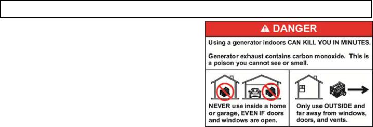
 NEVER run portable generators indoors or in garages, basements, or sheds. Portable generators should always be used at least 5 feet away from windows, doors, vents, or any other opening. Carbon Monoxide (CO) from a generator is deadly and can kill you in minutes. Read and follow all generator directions before use.
Transferring from Utility Power to Generator Power:
1.Move generator outdoors. Be sure your generator is located at least 5 feet from windows, doors or other openings to prevent dangerous carbon monoxide fumes from entering your home.
2.Insert the male plug of the Power Cord into the correct outlet on the generator.
3.Plug in the female connector of the Power Cord to the inlet (if provided) located on the bottom of the Transfer switch.
4.Turn OFF all circuit breakers in the Transfer switch and Main load center.
5.Start the generator outdoors, following the procedures described in the generator’s Owner’s Manual furnished by the manufacturer.
6.Turn ON the GENERATOR MAIN circuit breaker in the Transfer switch.
7.Turn ON individual circuit breakers in the Transfer switch and the Main Load Center up to the continuous wattage rating of your generator. If the Generator
Main breaker trips, you have overloaded the generator. Some circuit breakers must be turned OFF to avoid damage to the generator or loads being connected.
Transferring from Generator Power to Utility Power:
1.On the Transfer switch, turn OFF Generator MAIN breaker and turn ON Utility MAIN breaker. To do this, slide the interlock mechanism up with the left hand while turning ON the 200 amp circuit breaker.
2.Turn ON any branch circuit breakers in the Transfer switch and Main Load Center that are OFF.
3.Shut down the generator, following the procedures in the generator Owner’s Manual.
4.Unplug the power cord from the Transfer switch and then the generator.
5.Let the generator cool down before storing in a dry, secured location.
6.To ensure that your generator will work properly when you need it, it is important to start and run your generator under load regularly and keep the tank filled with fresh fuel. Perform the above steps at least ONCE A MONTH to keep the generator properly “exercised.”
|
Protected by US Patent No. US 6,861,596 B2 |
|
Generac Power Systems, Inc. |
|
Toll Free: 1-888-GENERAC |
|
www.generac.com |
|
0196970SBY |
© 2012 Generac Power Systems, Inc. All Rights Reserved. GenTran and Generac are registered trademarks of Generac Power Systems, Inc. |
PN 50925 Rev A |
3
 Loading...