

Page 1
g
DEH41025 Installation Instructions
Record Plus
™
Molded Case Circuit Breaker
Accessories
Rotary Handle Operator, Type
FENRH
Congratulations and thank you for choosing the
Record Plus
breakers. The UL-listed Type FENRH rotary handle
operator kit is suitable for use with the FE250 circuit
breaker series.
Record Plus
full line of integrated accessories. All units use the
latest in integrated modular circuit breaker
technology for flexibility in application and
maximizing the product’s utilization and
capabilities.
All
Record Plus
Underwriters Laboratories to the UL489 standard.
Record Plus
are designed and manufactured to exceed our global
customers’ high standards for reliability and quality.
Ensure that ALL electrical power supplies are OFF before
installing or removing any devices. The breaker, trip unit,
or accessories MUST ONLY be installed and serviced by
QUALIFIED personnel. See NEMA publication AB4.
™ family of current-limiting circuit
™circuit breakers are designed with a
™ circuit breakers are listed by
™circuit breakers and their accessories
WARNING: DANGER of electrical shock or injury.
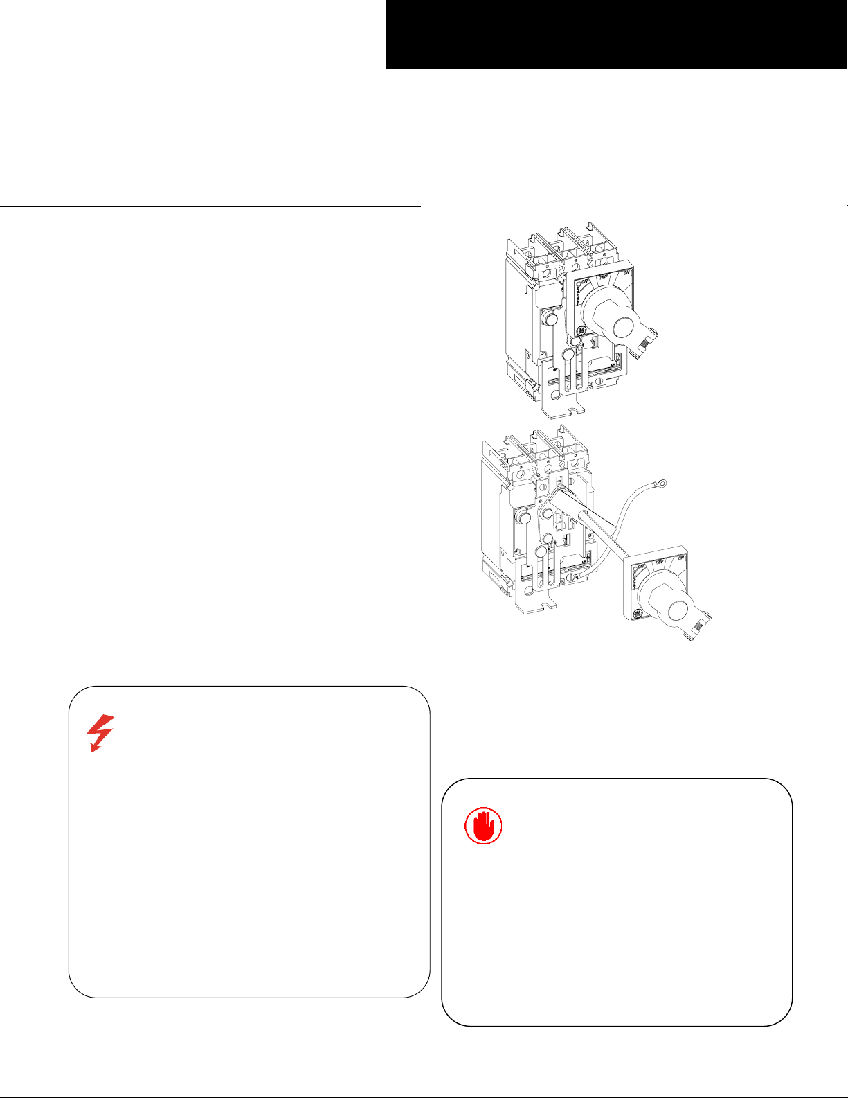
Figure 1b. FENRT
(Extended Shaft Door Mount).
Figure 1. FENRH Rotary Handle Kits mounted on
Record Plus
™FE250 circuit breaker.
Figure 1a. FENRN
(Shallow Door Mount).
AVERTISSEMENT:
d'électrocutions. S'assurer avant TOUTES
manipulations du disjoncteur que les différentes
sources d'alimentation sont en position OFF. Les
disjoncteurs, unités de protection, ou accessoires
doivent être installés par des personnes qualifiées et
habilitées. Lira NEMA publication AB4.
Danger contre les risques
DEH41025
CAUTION:
in equipment not specifically design to accept it.
Contact the equipment manufacturer for possible
equipment modifications.
ATTENTION:
employe dans un equipement non specialement
adapte a cet effet. Contactez le constructeur
concernant les possibles modifications a apporter
a l'equipement.
This product is NOT suitable for use
Cet appareil nedoit pas etre
Page 2
]
[2]
[3]
[4]
[5]
]
] [6]
[9]
Product Description
These instructions describe the installation
procedures for the rotary handle FENRH operating
mechanism accessory on
Record Plus
™ circuit
breakers, as illustrated in Figure 1.
The complete kits are available in the following
catalog number variants:
• FENRN provides the necessary parts for shallow
door mount of the handle on the breaker
mechanism through the enclosure door, with a
box depth of 5 29/32“ (150 mm), as shown in
Figure 1a. Maintain the dimension “H” [5
1
/32” (127.8 MM)] as shown in Figure 12.
• FENRT is for mounting the handle and
operator in enclosures with variable depth, as
shown in Figure 1b. Maintain the dimension
“H” [Min 6 13/16“ inches (173 mm) and Max
15 inches (381.0 mm)] as shown in Figure 13.
In addition, the individual kit parts are available as
follows:
• FENRM1 consists of the operating mechanism
for shallow door mounts of the handle to the
breaker.
• FENRM3 consists of the operating mechanism
for extended shaft door mount of the handle.
• FENRH is the handle assembly only.
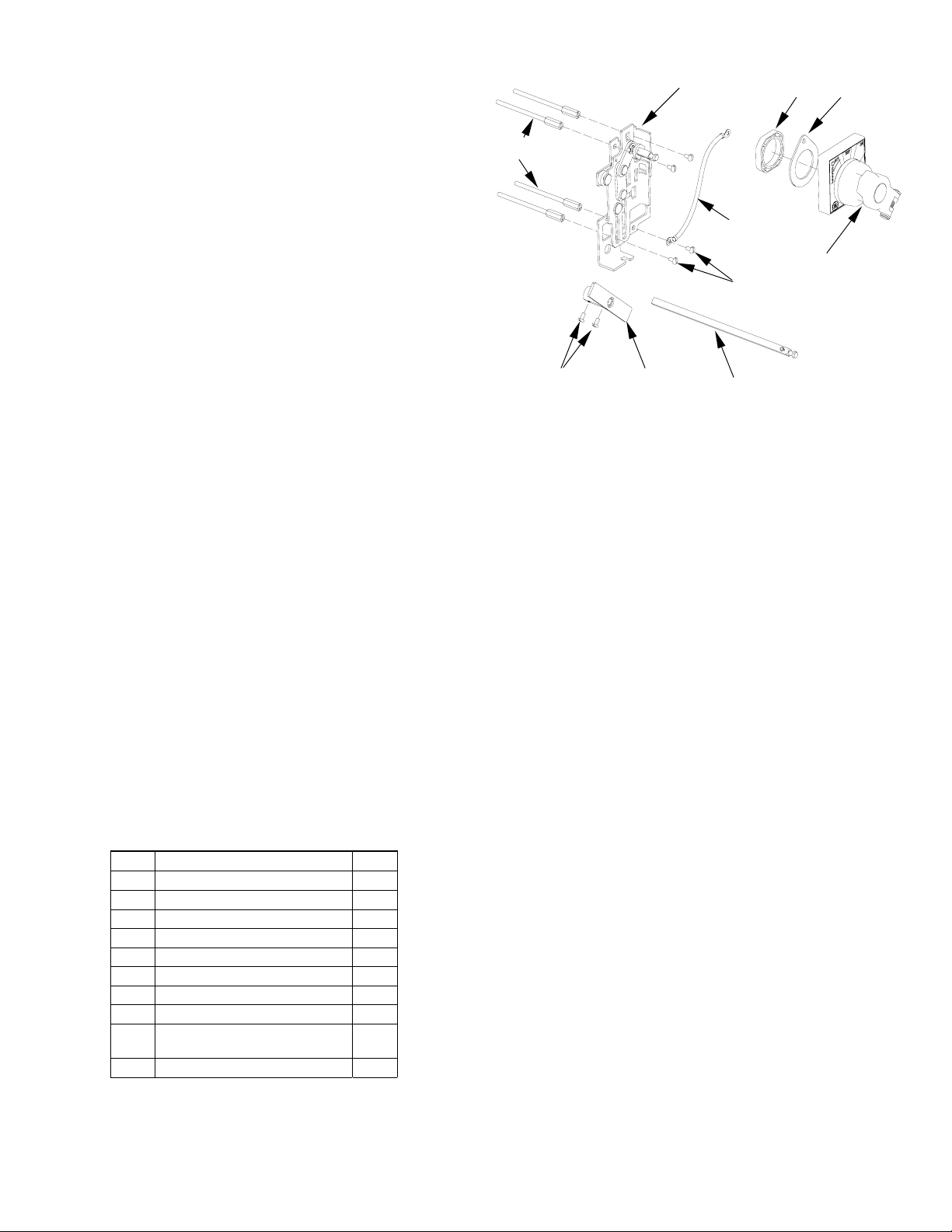
Step 1 – Unpack and Inspect
Unpack the rotary handle operating mechanism kit
and inspect the parts for any shipping damage.
Verify that all parts are supplied, as listed in
The parts are illustrated in Figure 2.
Note that the numbers in brackets in the following
figures and installation instructions refer to the item
numbers in
Table 1.
Item Description Qty.
1 Screw, #10-32 X 3 5/32" 4
2 Base-crank assembly 1
3 Grounding wire 1
4 Screw, #10-32 x 1/2" 4
5 Nut, plastic 1
6 Rotary handle assembly 1
7 Screw, #8-32 x 5/16" 4
8 Coupler Assembly 1
9 Extension shaft
assembly
10 Gasket 1
Table 1. List of parts included in the handle operator kits.
DEH41025
Table 1.
1
[1
[8
[10
Figure 2. Parts supplied in the FENRH rotary handle kits.
Step 2 – Install the Breaker and
Handle Operating Mechanism
1. Move the breaker handle to the OFF position.
2. Mount the breaker to the enclosure with the # 10-
32 x 3 5/32" screws [1], as illustrated in Figure 3.
Tighten the screws to 27 - 32 in-lb. Complete the
installation of the circuit breaker according to
installation instructions DEH40360.
3. Place the base-crank assembly [2] on the breaker,
as illustrated in Figure 4. Insert four #10-32 x 1/2"
screws [4] through the mounting holes in the
base and into the heads of the breaker mounting
screws [1], with the grounding wire [3] attached
to one of the screws. Tighten the screws to 27 - 32
in-lb. Secure the other end of the grounding wire
to a suitable ground location.
4. For kit FENRT variable-depth mounting only:
a. Measure the distance from the breaker-
mounting surface to the rotary handlemounting surface, H, as shown in Figures 8 &
13.
b. Cut the extension shaft [9] to the required
length “L” as illustrated in Figure 5.
c. Insert the shaft [9] upto 14 mm (35/64“ inch)
into the coupler [8] and secure it with #8-32 X
1
/32“ screws [7], as illustrated in Figure 6.
Tighten the screws to 16 - 20 in-lb.
d. Place the shaft [9] assembled with coupler
[8] on to the crank of the base-crank assembly
[2] and secure with #8-32
illustrated in Figure 7. Tighten the screws to 16
- 20 in-lb.
x 5/16“ screws [7], as
Page 3

]
]
[3]
]
]
[7]
]
]
]
[7]
[9]
]
[7]
[8]
[3]
[2]
[1]
Figure 3. Mounting the breaker in the enclosure.
[1
[1]
[2]
[4
[4
Figure 4. Mounting the mechanism base assembly
onto the breaker.
Figure 5. Cutting the extension shaft to the proper length.
DEH41025
Figure 6. Assemble the shaft and coupler.
Figure 7. Installing the extension shaft and coupler assembly.
[2
[6
[9
H
[8
Figure 8. Measuring the box depth for kit FENRT.
[9
Page 4

φ
t
n
)
e
]
]
[5]
Step 3 – Install the Rotary Handle
1. Drill holes on the enclosure door to
accommodate mounting the handle assembly, as
shown in Figure 9. The handle location on the
door is illustrated in Figure 10. Be sure that the
larger hole in Figure 9 is centered over the end
of the crank assembly or the extension shaft, as
appropriate.
2. Place the rotary handle assembly [6] on the
door with the locating feature, shown in Figure
11, placed in the small hole drilled in step 1.
Handle to be rotated to OFF position while
locking as shown in Fig10.
3. Secure the handle assembly to the door as
follows, depending on which kit variant you are
using:
a. For kit FENRN, use the plastic nut [5] to
secure the handle to the door.
b. For kit FENRT, if the length L of the shaft
[9] is less than 9 13/16 inches (250 mm),
use the plastic nut [5] to secure the
handle to the door. If the shaft is longer
than 9 13/16 inches (250 mm), use the
funnel [10] to secure the handle to the
door.
4. Close the enclosure door and verify that the end
of the crank assembly or the extension shaft, as
appropriate, locks into the center of the handle
assembly, as illustrated in Figure 1.
Center of Top Righ
Breaker Mounting Hole
Figure 9. Hole pattern for mounting the handle assembly
on the enclosure door.
DEH41025
0.24
[6.00]
3.15” min
(80.0)
3.15” mi
Figure 10. FENRH handle location on the enclosure
door.
Locating Featur
[6
Figure 11. Installing the rotary handle assembly.
[10
(80.0
Page 5

]
[
]
E
R
n
Step 4 – Operation
Breaker operation with the rotary handle is as
follows:
Figure 12 and Figure 13 are outline views of completed installations with dimensions.
4.11”
[104.40]
ENCLOSURE COVER
MAX.GA*12)
3.7”
[94.0]
Figure 12. Outline view of completed FENRN installatio
• Close the enclosure door in “OFF” position of
breaker.
• To close the breaker, rotate the rotary handle
clockwise from the
OFF position to ON.
• To open the breaker, rotate the handle
counterclockwise from
ON to OFF.
• The enclosure door cannot be opened when
the breaker is
ON.
• Open the enclosure door in “OFF” position
of breaker only.
[1.38]
1.38
35.00
35.00
[35.00]
[1.38]
(MIN GA*16
185.6
0.24”
[6.00]
4.94”
[125.50]
[170.0
[7.3]
7.3
7.3]
185.6
[185.6]
6.00
6.7”
OF HANDL
OF BREAKE
7.68”
5.03
[127.8]
H
0.9”
[195.0]
”
[22.5
17.64”
[448]
MAX
H
15
”
[381.0]
MAX
6.8”
[173.0]
MIN
Figure 13. Outline view of completed FENRT installation
DEH41025
Page 6

r
e
k
Locking the Rotary Handl
Assembly
The rotary handle assembly is designed to
accommodate from one to three 13/64 in. (5 mm)
to 5/16 in. (8 mm) padlocks to lock the breaker in
”OFF”
the
Insert the padlock shaft into the slot in the padloc
lever with the breaker in
prevent closing the breaker during maintenance,
illustrated in Figure 14b.
position, as shown in Figure 14a.
“OFF”
position, to
One pad Lock can be
Introduced to lock
the rotary handle
Figure 14a. Locking rotary handle assembly
Slot for Pad lock
Breaker position
Indication through
this slot
Figure 14b. Locking the circuit breaker
Operating mechanism
These instructions do not cover all details or variations in equipment nor do they provide for every possible
contingency that may be met in connection with installation, operation, or maintenance. Should furthe
information be desired or should particular problems arise that are not covered sufficiently for the purchaser’s
purposes, the matter should be referred to the GE Company. The circuit breaker is a sealed unit that contains no
user-serviceable parts. Tampering with the seal will void the warranty.
g
GE Consumer & Industrial
________________________________________________________
General Electric Company
41 Woodford Ave., Plainville, CT 06062
www.geindustrial.com
DEH41025 03 R0625431 © 2004 General Electric Company
DEH41025
 Loading...