

Page 1
r
f
A
r
g
Congratulations and thank you fo
choosing the Record PlusTM family o
current limiting circuit breakers.
Record Plus
designed to provide overload and short
circuit protection to electrical distribution
and utilization equipment.
All units use the latest in integrated
modular circuit breaker technology to allow
flexibility in application and precise control
of abnormal circuit conditions.
All Record Plus
by Underwriters Laboratories to UL489
standard.
Record Plus
GE high - performance, reliability and
quality standards.
TM
- circuit breakers are
TM
circuit breakers are listed
TM
- circuit breakers meet the
Caution: This product is NOT suitable for use
in equipment not specifically design to accept
it. Contact equipment manufacturer fo
possible equipment modifications.
Important: Cet appareil nedoit pas etre
employe dans un equipement non
specialement adapte a cet effet. Contactez le
constructeur concernant les possibles
modifications a apporter a l'equipemen.
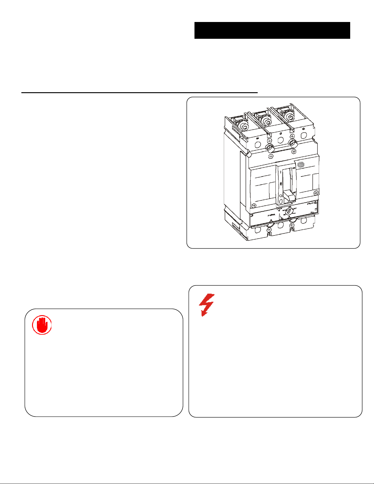
DEH40360 Installation Instructions
TM
Record Plus
Molded Case Circuit Breaker
(FE250)
Warning: DANGER of Electrical shock or injury.
Ensure ALL electrical power supplies are "OFF” before
installing or removing any devices. The breaker, trip
unit or accessories, MUST ONLY be installed and
serviced by QUALIFIED personnel, see NEM
publication AB4.
Avertissement: Danger contre les risques
d'électrocutions. S'assurer avant toutes manipulations
du disjoncteur que les différentes sources
d'alimentation sont en position «OFF». Les
disjoncteurs, unités de protection ou accessoires
doivent être installés par des personnes qualifiées et
habilitées. Lira NEMA publication AB4.
Page 2

S
pp
r
S
f
r
r
r
C*
tep 1, Unpack and inspect
Unpack the breaker and inspect it for any
shipping damage. Ensure the breaker has the
proper ampere, voltage and interrupting
ratings for the application. Next, using the
instructions supplied with the rating plug,
install the plug into the main breaker body.
Available rating plugs along with catalog
numbers are listed in Table 2 and shown in
Figure1, (see color-coding). Now install the
accessories (Step 9) and terminal lugs ( Step
3) using supplied installation instructions.
Check all accessories for proper voltage
ratings, installation, wiring routing and
operation. Attach appropriate labels to side o
the breaker if internal accessories have been
installed.
Step 2, Installation
Using Figure 2, drill and tap all mounting
holes and make any necessary front panel
escutcheon cut outs. Using the breake
hardware kit, FEMSK1 - which includes fou
#10-32 x 2-7/8in screws and lock washers o
FEMSK3 - which includes four #8-32 x 27/8in screws and lock washers, mount the
breaker.
Torque #8-32 screws to 20 lb-in (2.25Nm)
and the #10- 32 screws to 32 lb-in (3.6Nm).
B 87 mm 3.43 in F 64 mm 2.52 in
D 27 mm 1.06 in H 125.5 mm 4.94 in
* With security cover, without C = 31.8mm(1.25in) and G
= 92.13mm(3.627in)
Check to make sure all terminals are torqued to
the proper value. Reinstall the terminal (IP20)
covers insuring that they are firmly seated, see
figure 5.
150A-Lug Kit FCAL15 (Al)
Cu/Al wire, strip length-9/16 – 11/16 inch (14 – 18mm)
#14 - 12AWG Torque to 35 lb-in (3.95 Nm)
10 - 6AWG Torque to 70 lb-in (7.90 Nm)
#4-3/0AWG Torque to 150 lb-in (16.95Nm)
250A - Lug kit FCAL16 (Al)
Cu/Al wire, strip length- 3/4 – 7/8 inch (19 – 23mm)
#8 - 1AWG Torque to 175 lb-in (19.8Nm)
#1/0 – 350Kcmil Torque to 275 lb-in (31Nm)
250Kcm max with Cu wire
Warning: Danger! It is important that the
terminal covers be installed correctly to ensure
proper circuit breaker operation, see figure 5.
Important: Danger! Il es import de verifier que
tout cuvercle ou cache de protection est
correctement installe afin d'assurer le bon
fonctionnement de l'a
Table 1 - Dimensions for figure 2
34 mm 1.34 in G* 96.2 mm 3.78 in
E 35 mm 1.38 in
tep 3, Wire Terminal Connections
areil.
Rating Plug
Type
Breaker
Sensor
Amps
Color Code
Rating Plug
Amps
3
7
10
15
20 B0020
25 B0025 D0025
30 D0030
35
40 D0040
45
50 D0050 G0050
55
60 D0060 G0060
70 G0070 H0070
80 G0080 H0080
90 G0090 H0090
100 G0100 H0100 K0100
110 G0110 H0110 K0110
125 G0125 H0125 K0125
150 H0150 K0150
175 K0175
225 K0225
250 K0250
Note: When using aluminum wire, use a joint
compound recommended by the wire manufacturer.
Important: Dans les cas d'emploi de cable
aluminum, utilizez le lubricant recommende by pa
le fabricant.
25 60 125 150 250
Light
Grey White Brown Yellow Orange
Table 2
FERP3…
Figure 1,
Figure 2, Breaker mounting, Escutcheon and orientation
Page 3

r
Step 4, Adjustments
SMR1 digital RMS trip unit: Features a fixed
instantaneous trip function and an adjustable trip
function Im, which can shorten the trip time to
approximately 100ms, for over current above 2x
to 13x. To set the Im value, using switch dial,
select a specific value of St. See figure 3. The St
set point value is a multiple of the installed rating
plug - rated current (Ir),
Im = St x Ir.
Step 5, Circuit breaker performance and
operation
The breaker contact status is indicated by the
handle position, and the positions are marked on
either side of the handle escutcheon, clearly
showing the status of the breaker contacts. ON
and/or I indicate breaker is ON and OFF and/or O
indicate breaker is OFF.
The breaker tripped position
is indicated by the symbol.
To close the breaker from the OFF position moves
the handle to the ON position. To close the
breaker from the trip position, first move the
handle fully to the OFF (reset) position then to the
ON position. See Figure 6.
A Push-To-Trip button is provided for convenience
of testing the mechanical trip operation of the
breaker.
The Push-To-Trip should be tested annually.
Caution: Automatic tripping of the circuit breake
may indicate a system problem. Identify and
correct any problem before turning the device on
again.
Important: Le declenchement automatique de
disjoncteru, peut indiquer un probleme de circuit.
Identifiez et corrigez le probleme avant de
refermer l'appareil.
Figure 3, SMR1 trip unit St (2x –13x), Im = St x Ir
St Dial
Terminal (IP20) covers,
Line and load
Figure 5, Setting adjustment, tamper resistant cover
and terminal (IP20) cover
Figure 6 - Mechanically
Operating Circuit breaker
Page 4

S
r
r
r
r
r
tep 6, Troubleshooting:
Ensure that breaker is installed correctly and all
terminal connections are torqued pe
instructions.
If the breaker fails to close, check:
1. For overloads and short circuit on the system.
2. Handle position - TRIPPED - reset by moving
handle fully to OFF position and then to the
ON position, see figure 6.
3. Under voltage trip is supplied with rated
voltage.
4. Shunt trip is de-energized and no trip signal
exists.
5. Breaker trip unit settings are properly
adjusted.
If technical assistance is required, contact you
local sales office. In the US call GE Post Sales
Customer Service, 1 888 437 3765.
Step 7, Maintenance:
Generally, no maintenance is required but it is
recommended that the breaker be cleaned and
inspected on an annual basis.
Warning: Danger of electrical shock or injury.
Turn off power supplies ahead of equipment
before attempting to service or accessories.
Important: Danger d’electrocution. Coupe
l’alimenation avant d’effectuer toute action
d’entretien.
Operate the breaker push to test button and
toggle the handle several times, testing the
mechanical operation of the device. If there are
any signs of damage or if the mechanism is
sluggish or sticky, replace the breaker.
For abnormal or heavy duty conditions refer to
NEMA publication AB4 and recommended
practices of NFPA70B.
Step 8, Storage:
Store in a dry, dust free, environment protected
from corrosion. Long-term storage should be in
the original shipping carton. Temperature range
o
–40
C to +40oC.
Step 9, Accessories:
For full details of the accessories and their
application, contact your local GE
representatives. When installing accessories
read
the accompanying accessory installation
instruction and follow carefully all cautions and
warnings.
These instructions do not cover all details or variations in equipment nor do they provide fo
every possible contingency that may be met in connection with installation, operation, o
maintenance. Should further information be desired or should particular problems arise that are
not covered sufficiently for the purchaser’s purposes, the matter should be referred to the GE
g
Company. The circuit breaker is a sealed unit, which contains no user serviceable parts.
Tampering with seal will void warrant.
Apply Accessory Label to
side of breaker
Outer 2 positions
Right pocket auxiliary
Switch ID
Outer 2 positions
Left pocket auxiliary
Switch ID
Inner Position Left pocket
shunt-trip/under voltage
Trip Bell-alarm ID
Figure 7, Typical accessories.
See buylog® for details
Shunt trip/Under
Voltage Module
GE Consumer & Industrial
41 Woodford Avenue
Plainville, CT USA 06062
www.geconsumerandindustrial.com
DEH40360 05 R0833843 © 2004 General Electric Company
 Loading...