

Page 1

GE
Entellisys™ Low Voltage Switchgear
System Test Kit
User Manual
Page 2

DEH-233
Warnings, Cautions, and Notes as used in this publication
Warnings
WARNING! Warning notices are used in this publication to emphasize that hazardous voltages, currents,
or other conditions that could cause personal injury exist in this equipment or may be associated with its
use.
Warning notices are also used for situations in which inattention or lack of equipment knowledge could
cause either personal injury or damage to equipment.
Cautions
CAUTION: Caution notices are used for situations in which equipment might be damaged if care is not
taken.
Notes
NOTE: Notes call attention to information that is especially significant to understanding and operating
the equipment.
This document is based on information available at the time of its publication. While efforts have been
made to ensure accuracy, the information contained herein does not cover all details or variations in
hardware and software, nor does it provide for every possible contingency in connection with installation,
operation, and maintenance. Features may be described in here that are not present in all hardware and
software systems. GE Consumer & Industrial assumes no obligation of notice to holders of this document
with respect to changes subsequently made.
GE Consumer & Industrial makes no representation or warranty, expressed, implied, or statutory, with
respect to, and assumes no responsibility for the accura cy, completeness, sufficiency, or usefulness of the
information contained herein. No warrantees of merchantability or fitness for purpose shall apply.
Entellisys™, EntelliGuard™, and FlexLogic™ are trademarks of the General Electric Company.
Modbus RTU is a registered trademark of AEG Schneider Automation.
©Copyright 2005 General Electric
All Rights Reserved
Page 3

How to contact us
Please have your Entellisys System Summary # and Sub # ready when calling. This information can be
found on the Entellisys HMI on the System Health screen by clicking the Job Info button.
Post Sales Service
GE Switchgear
510 Agency Road
West Burlington, IA 52655
Phone (toll free): 1-888-437-3765
Additional information:
www.entellisys.com/support
Page 4

Contents
1 System Test Kit
1.1 Introduction. . . . . . . . . . . . . . . . . . . . . . . . . . . . . . . . . . . . . . . . . . . . . . . . . . . . . . . . . . . . . . . . . . . . . . . . . . . . . . . . . . . . . . . . . . . 7
1.2 Test overview/architecture. . . . . . . . . . . . . . . . . . . . . . . . . . . . . . . . . . . . . . . . . . . . . . . . . . . . . . . . . . . . . . . . . . . . . . . . . . . . 10
1.3 Test kit hardware/specs . . . . . . . . . . . . . . . . . . . . . . . . . . . . . . . . . . . . . . . . . . . . . . . . . . . . . . . . . . . . . . . . . . . . . . . . . . . . . . 11
1.3.1 Test Unit PC . . . . . . . . . . . . . . . . . . . . . . . . . . . . . . . . . . . . . . . . . . . . . . . . . . . . . . . . . . . . . . . . . . . . . . . . . . . . . . . . . . . . . 11
1.3.2 Test kit power cord . . . . . . . . . . . . . . . . . . . . . . . . . . . . . . . . . . . . . . . . . . . . . . . . . . . . . . . . . . . . . . . . . . . . . . . . . . . . . . 11
1.3.3 Test connector (System Test Kit to EntelliGuard Messenger cable). . . . . . . . . . . . . . . . . . . . . . . . . . . . . . . . . . 12
1.3.4 USB-to-USB cable . . . . . . . . . . . . . . . . . . . . . . . . . . . . . . . . . . . . . . . . . . . . . . . . . . . . . . . . . . . . . . . . . . . . . . . . . . . . . . . 12
1.4 Getting started . . . . . . . . . . . . . . . . . . . . . . . . . . . . . . . . . . . . . . . . . . . . . . . . . . . . . . . . . . . . . . . . . . . . . . . . . . . . . . . . . . . . . . . 13
1.4.1 Start up. . . . . . . . . . . . . . . . . . . . . . . . . . . . . . . . . . . . . . . . . . . . . . . . . . . . . . . . . . . . . . . . . . . . . . . . . . . . . . . . . . . . . . . . . 13
1.4.2 Self Test. . . . . . . . . . . . . . . . . . . . . . . . . . . . . . . . . . . . . . . . . . . . . . . . . . . . . . . . . . . . . . . . . . . . . . . . . . . . . . . . . . . . . . . . . 14
1.4.3 Main Menu. . . . . . . . . . . . . . . . . . . . . . . . . . . . . . . . . . . . . . . . . . . . . . . . . . . . . . . . . . . . . . . . . . . . . . . . . . . . . . . . . . . . . . 15
1.4.4 General navigation . . . . . . . . . . . . . . . . . . . . . . . . . . . . . . . . . . . . . . . . . . . . . . . . . . . . . . . . . . . . . . . . . . . . . . . . . . . . . . 16
1.5 Download switchgear configuration. . . . . . . . . . . . . . . . . . . . . . . . . . . . . . . . . . . . . . . . . . . . . . . . . . . . . . . . . . . . . . . . . . . 16
1.5.1 Direct Connect Download from HMI . . . . . . . . . . . . . . . . . . . . . . . . . . . . . . . . . . . . . . . . . . . . . . . . . . . . . . . . . . . . . . 17
1.5.1.1 System Configuration Download Link communication. . . . . . . . . . . . . . . . . . . . . . . . . . . . . . . . . . . . . . . . 20
1.5.2 Last Download . . . . . . . . . . . . . . . . . . . . . . . . . . . . . . . . . . . . . . . . . . . . . . . . . . . . . . . . . . . . . . . . . . . . . . . . . . . . . . . . . . 20
1.6 Test Menu. . . . . . . . . . . . . . . . . . . . . . . . . . . . . . . . . . . . . . . . . . . . . . . . . . . . . . . . . . . . . . . . . . . . . . . . . . . . . . . . . . . . . . . . . . . . 21
1.6.1 Overcurrent Protection Test. . . . . . . . . . . . . . . . . . . . . . . . . . . . . . . . . . . . . . . . . . . . . . . . . . . . . . . . . . . . . . . . . . . . . . 22
1.6.1.1 Functions . . . . . . . . . . . . . . . . . . . . . . . . . . . . . . . . . . . . . . . . . . . . . . . . . . . . . . . . . . . . . . . . . . . . . . . . . . . . . . . . . . 22
1.6.1.2 Test methods . . . . . . . . . . . . . . . . . . . . . . . . . . . . . . . . . . . . . . . . . . . . . . . . . . . . . . . . . . . . . . . . . . . . . . . . . . . . . . 23
1.6.1.3 Pre-Defined Overcurrent Protection Test. . . . . . . . . . . . . . . . . . . . . . . . . . . . . . . . . . . . . . . . . . . . . . . . . . . . . 23
1.6.1.4 User-Defined Overcurrent Protection test. . . . . . . . . . . . . . . . . . . . . . . . . . . . . . . . . . . . . . . . . . . . . . . . . . . . 26
1.6.1.5 Automatic Trip Time Curve Test . . . . . . . . . . . . . . . . . . . . . . . . . . . . . . . . . . . . . . . . . . . . . . . . . . . . . . . . . . . . . 29
1.6.2 Relay Protection Test . . . . . . . . . . . . . . . . . . . . . . . . . . . . . . . . . . . . . . . . . . . . . . . . . . . . . . . . . . . . . . . . . . . . . . . . . . . . 32
1.6.2.1 Pre Defined Test. . . . . . . . . . . . . . . . . . . . . . . . . . . . . . . . . . . . . . . . . . . . . . . . . . . . . . . . . . . . . . . . . . . . . . . . . . . . 34
1.6.2.2 User Defined Test. . . . . . . . . . . . . . . . . . . . . . . . . . . . . . . . . . . . . . . . . . . . . . . . . . . . . . . . . . . . . . . . . . . . . . . . . . . 37
1.6.2.3 Relay Protection Test Results screen . . . . . . . . . . . . . . . . . . . . . . . . . . . . . . . . . . . . . . . . . . . . . . . . . . . . . . . . 41
1.7 Ground Fault Defeat. . . . . . . . . . . . . . . . . . . . . . . . . . . . . . . . . . . . . . . . . . . . . . . . . . . . . . . . . . . . . . . . . . . . . . . . . . . . . . . . . . 42
1.7.1 Setup . . . . . . . . . . . . . . . . . . . . . . . . . . . . . . . . . . . . . . . . . . . . . . . . . . . . . . . . . . . . . . . . . . . . . . . . . . . . . . . . . . . . . . . . . . . 43
1.8 Summary of Protection. . . . . . . . . . . . . . . . . . . . . . . . . . . . . . . . . . . . . . . . . . . . . . . . . . . . . . . . . . . . . . . . . . . . . . . . . . . . . . . 44
1.9 Manual Breaker Injection . . . . . . . . . . . . . . . . . . . . . . . . . . . . . . . . . . . . . . . . . . . . . . . . . . . . . . . . . . . . . . . . . . . . . . . . . . . . . 45
1.9.1 Setup . . . . . . . . . . . . . . . . . . . . . . . . . . . . . . . . . . . . . . . . . . . . . . . . . . . . . . . . . . . . . . . . . . . . . . . . . . . . . . . . . . . . . . . . . . . 46
1.9.2 Manual circuit breaker injection input range. . . . . . . . . . . . . . . . . . . . . . . . . . . . . . . . . . . . . . . . . . . . . . . . . . . . . . 47
1.10 Post Analysis Selection screen . . . . . . . . . . . . . . . . . . . . . . . . . . . . . . . . . . . . . . . . . . . . . . . . . . . . . . . . . . . . . . . . . . . . . . . 48
1.11 Test Reports . . . . . . . . . . . . . . . . . . . . . . . . . . . . . . . . . . . . . . . . . . . . . . . . . . . . . . . . . . . . . . . . . . . . . . . . . . . . . . . . . . . . . . . . 48
1.12 Test kit administration. . . . . . . . . . . . . . . . . . . . . . . . . . . . . . . . . . . . . . . . . . . . . . . . . . . . . . . . . . . . . . . . . . . . . . . . . . . . . . . 51
1.12.1 HMI setup. . . . . . . . . . . . . . . . . . . . . . . . . . . . . . . . . . . . . . . . . . . . . . . . . . . . . . . . . . . . . . . . . . . . . . . . . . . . . . . . . . . . . . 52
1.12.2 Disk cleanup . . . . . . . . . . . . . . . . . . . . . . . . . . . . . . . . . . . . . . . . . . . . . . . . . . . . . . . . . . . . . . . . . . . . . . . . . . . . . . . . . . . 53
1.12.3 System Information . . . . . . . . . . . . . . . . . . . . . . . . . . . . . . . . . . . . . . . . . . . . . . . . . . . . . . . . . . . . . . . . . . . . . . . . . . . . 54
1.12.4 Test Kit Validation Test . . . . . . . . . . . . . . . . . . . . . . . . . . . . . . . . . . . . . . . . . . . . . . . . . . . . . . . . . . . . . . . . . . . . . . . . . 55
1.12.4.1 Customer Validation Tests. . . . . . . . . . . . . . . . . . . . . . . . . . . . . . . . . . . . . . . . . . . . . . . . . . . . . . . . . . . . . . . . . 55
1.12.4.2 Factory Test only. . . . . . . . . . . . . . . . . . . . . . . . . . . . . . . . . . . . . . . . . . . . . . . . . . . . . . . . . . . . . . . . . . . . . . . . . . 56
1.13 Long-term maintenance. . . . . . . . . . . . . . . . . . . . . . . . . . . . . . . . . . . . . . . . . . . . . . . . . . . . . . . . . . . . . . . . . . . . . . . . . . . . . 56
1.13.1 Motherboard battery maintenance . . . . . . . . . . . . . . . . . . . . . . . . . . . . . . . . . . . . . . . . . . . . . . . . . . . . . . . . . . . . . 56
Contents 5
Page 5

1.13.2 Test kit care. . . . . . . . . . . . . . . . . . . . . . . . . . . . . . . . . . . . . . . . . . . . . . . . . . . . . . . . . . . . . . . . . . . . . . . . . . . . . . . . . . . . 57
1.13.2.1 Handling the test kit. . . . . . . . . . . . . . . . . . . . . . . . . . . . . . . . . . . . . . . . . . . . . . . . . . . . . . . . . . . . . . . . . . . . . . . 57
1.13.2.2 Cables. . . . . . . . . . . . . . . . . . . . . . . . . . . . . . . . . . . . . . . . . . . . . . . . . . . . . . . . . . . . . . . . . . . . . . . . . . . . . . . . . . . . 57
1.13.2.3 Power . . . . . . . . . . . . . . . . . . . . . . . . . . . . . . . . . . . . . . . . . . . . . . . . . . . . . . . . . . . . . . . . . . . . . . . . . . . . . . . . . . . . 57
1.13.2.4 Cleaning the LCD screen. . . . . . . . . . . . . . . . . . . . . . . . . . . . . . . . . . . . . . . . . . . . . . . . . . . . . . . . . . . . . . . . . . . 58
1.13.2.5 Cleaning the keyboard . . . . . . . . . . . . . . . . . . . . . . . . . . . . . . . . . . . . . . . . . . . . . . . . . . . . . . . . . . . . . . . . . . . . 58
1.13.2.6 Cleaning the fan filter . . . . . . . . . . . . . . . . . . . . . . . . . . . . . . . . . . . . . . . . . . . . . . . . . . . . . . . . . . . . . . . . . . . . . 58
1.14 Troubleshooting. . . . . . . . . . . . . . . . . . . . . . . . . . . . . . . . . . . . . . . . . . . . . . . . . . . . . . . . . . . . . . . . . . . . . . . . . . . . . . . . . . . . . 59
A Definition of terms
6Contents
Page 6

1 System Test Kit
1.1 Introduction
The Entellisys™ System Test Kit is a portable test instrument designed for field testing of the
Entellisys Low Voltage Switchgear System.
The test kit includes the following features:
• Simulates power line characteristics for a single circuit breaker in the Entellisys Low Voltage
System
• Verifies the function/operation of the protection system
• Overcurrent Protection Tests – Long Time, Short Time, Instantaneous and Ground Fault
Protection Tests
• Single Point Relay Protection Tests (Overvoltage, Undervoltage, Over Frequency, Under
Frequency, Power Reversal and Phase Loss, High Current Test)
• Verifies the calibration of the trip time current curve
• Verifies the operation of the circuit breaker actuation in “Trip mode”
• Performs tests without trips in “No Trip mode”
• Ground Fault Defeat function provides temporarily suspension of all Ground Fault protection
in the system
• Automatically retrieves system configuration for increased productivity
• Displays a summary of all protection configuration
• Saves test results to be reviewed later
• Windows Interface for ease of use
• Operation from 120 Vac
The test kit Interface with the system is through the EntelliGuard™ Messenger protection unit.
The interface consists of 7 analog and several digital channels representing actual power li ne
characteristics. The signals are injected directly into the Messenger A/D converters. This tests
the entire Entellisys System, excluding the CTs, the CT interface (burden resistors) inside the
Messenger, and the PTs.
Introduction 7
Page 7
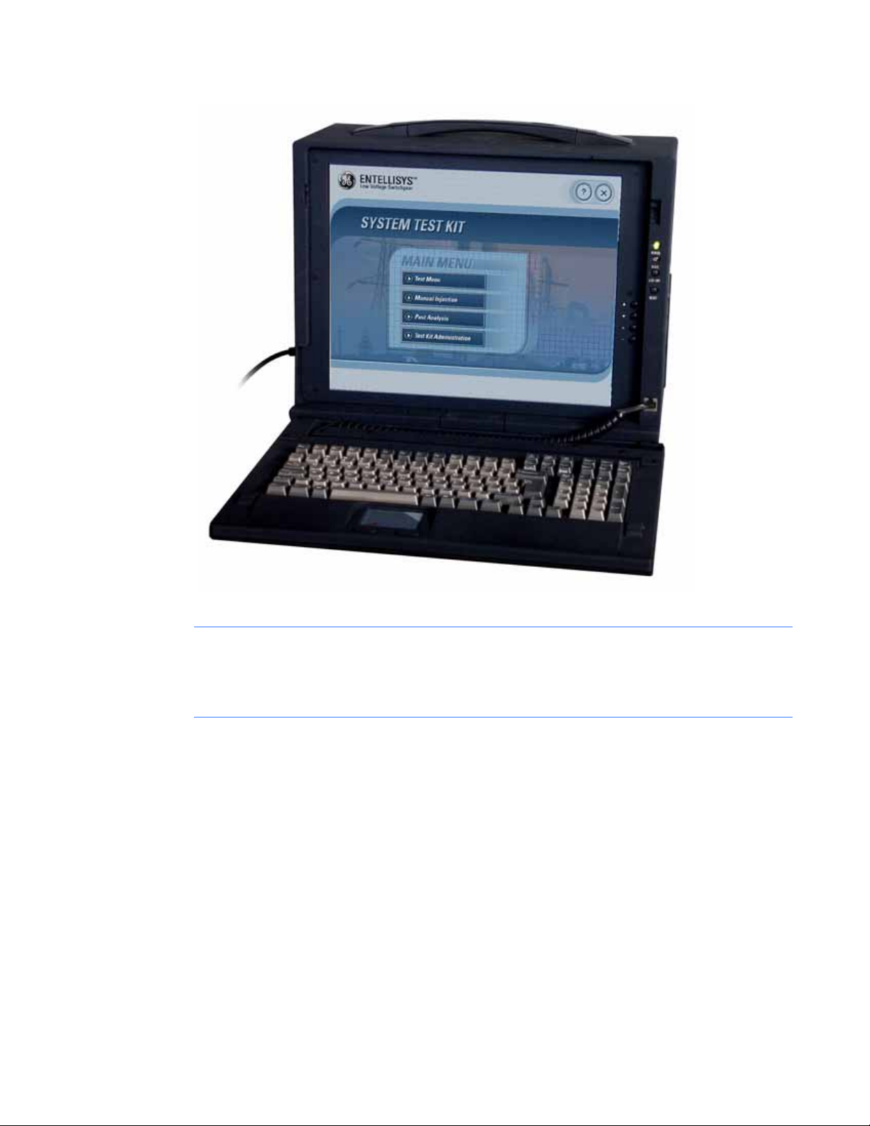
Figure 1-1 System Test Kit photograph
CAUTION: Tests conducted with the System Test Kit must be performed with the circuit
breaker de-energized and racked-out to the test position. The test inputs will supersede the
normal current and voltage inputs which disables normal protection, preventing response to
fault conditions.
System Test Kit8
Page 8
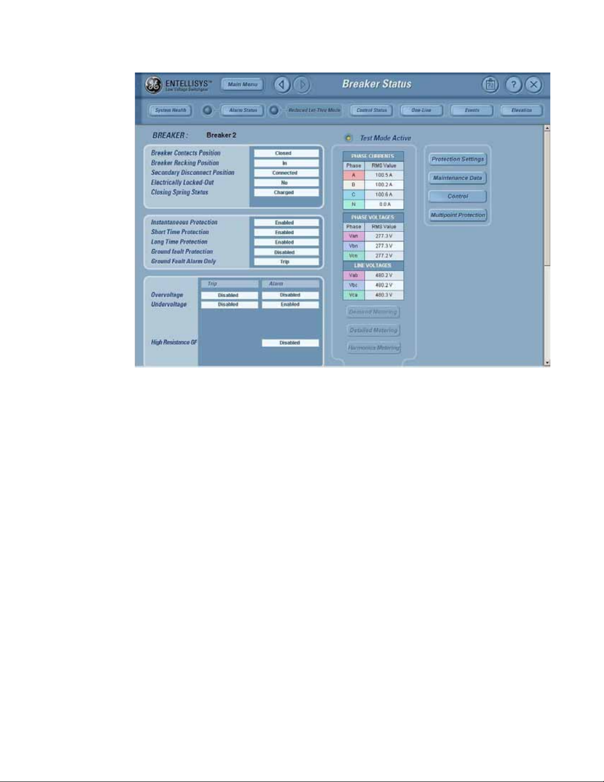
Figure 1-2 HMI screen showi ng circuit breaker in Test Mode
The HMI will indicate that the unit is in Test Mode. It will also display the output analog
waveforms in response trip test.
Introduction 9
Page 9
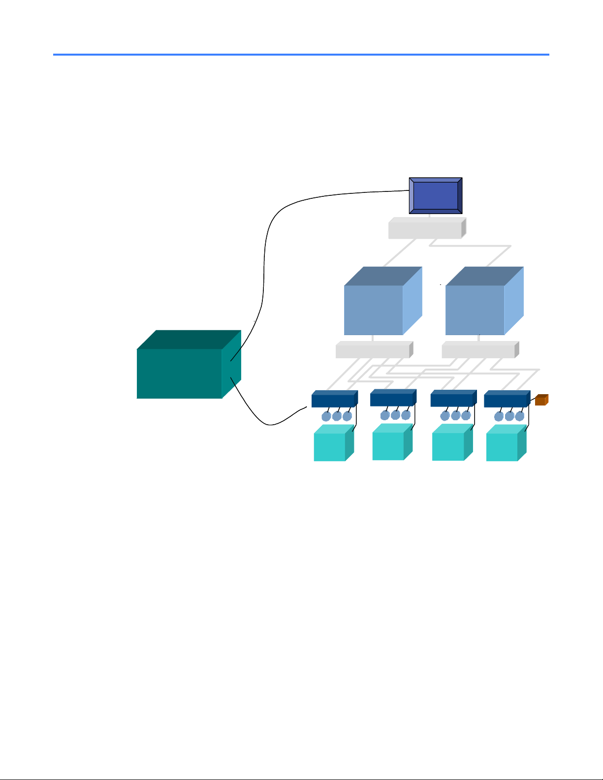
1.2 Test overview/architecture
The System Test Kit uses the method of low voltage injection to perform its tests. The test kit
drives these low level voltages (10V p-p) into individual test input s of the Messenger's A/D
converter. Basic protection scheme, Functional protection, and Single Point Relay protection of
the entire system can be tested using low voltage injection from the System Test Kit.
Figure 1-3 Entellisys system architecture with System Test Kit
System C onfiguration
System C onfiguration
Dow nload Link
Dow nload Link
USB
USB
CPU A CPU B
CPU A CPU B
HMI
HMI
System Interface
System Interface
E t h e r n e t S w itc h
E t h e r n e t S w itc h
System
System
Test Kit
Test Kit
USB
USB
DB-25
DB-25
DB-25
DB-25
Test C onnector
Test C onnector
Messenger
Messenger
CT CT
CTCT CTCT
CT
CTCT
Breaker
Breaker
Messenger
Messenger
CT CT
CTCT CTCT
CT
CTCT
Breaker
Breaker
M essenger Sw itchM essenger Sw itch
M essenger Sw itchM essenger Sw itchM essenger Sw itchM essenger Sw itch
M essenger
M essenger
CTCT
CTCTCT
CTCT
CTCT
Breaker
Breaker
Messenger
Messenger
CT CT
CTCT CTCT
CT
CTCT
Breaker
Breaker
PT’s
PT’s
System Test Kit10
Page 10

1.3 Test kit hardware/specs
All the digital signals given from the test kit and accepted from the test kit are active low TTL
signals.
Table 1-1 Actual System Test Kit output accuracy
Sl.No Parameter Accuracy
1. Voltage ±0.1%
2. Frequency ±0.05 Hz
3. Phase angle ±0.1
4. Time Stamping ±0.5 ms
Required accuracy for protection testing is based on the accuracy of Entellisys S ystem
Accuracy.
Table 1-2 System accuracy with the test kit
Sl.No Protection Accuracy
1. Current Protection 1X ±6.5%
2. Relay Protection ±6.5%
3. Ground Fault 0.2X ±2%
1.3.1 Test Unit PC
System Test Kit PC is a rugged Portable PC unit with multiple PCI slots. It uses two data
acquisition cards to generate required test signals for injecting for testing protection elements
in the Entellisys Low Voltage Switchgear system.
The test kit is entirely kiosked and runs on the Windows 2000 operating system.
1.3.2 Test kit power cord
The test kit power cord is designed with integr ated surge protection equipment to protect the
system from normal power anomalies.
Once the surge protector is triggered, it will be grounded (which can be detected by the surge
protector; the LED will be ON). Once this occurs, the power cord will need to be replaced.
NOTE: The power cord must be replaced with the same cord to ensure proper operation.
Replacement Power Cord: GE CAT# ETSTESTKITCBLSRG
Test kit hardware/specs 11
Page 11

1.3.3 Test connector (System Test Kit to EntelliGuard Messenger cable)
The test connector is a 25-pin DB Type connector used for injecting signals to/from the Test Kit
to the Messenger.
• Seven channels are analog outputs that represent three-phase voltages and currents plus a
neutral. These –10V to +10V sinusoidal analog outputs are injected directly into a
Messenger's A/D converter via the Messenger front panel. The test kit changes the waveform
characteristics of these sinusoids to test the different protection schemes.
NOTE: If the cable is lost or broken, it must be replaced with the same cable to ensure proper
operation.
Replacement “Test Connector” Cable: GE CAT# E TSTESTKITCBLMSR
1.3.4 USB-to-USB cable
The test kit communicates with the Entellisys Low Voltage HMI to download system
configuration, preventing the operator from entering it manually.
A USB-to-USB cable, running a peer-to-peer network communication bridge, is used between
the test kit and the HMI for communication. The USB-to-USB bridge arrives pre-configured in
both the HMI and the test kit. See HMI setup
on page 52 for configuration details.
To enable this communication, from the Test Kit Administration menu, enter the HMI IP
address in the HMI Setup window.
NOTE: Special USB drivers for the cable supplied are preinstalled on the HMI. If the cable is lost
or broken, it must be replaced with the same model.
Replacement USB to USB Cable: GE CAT# ETSTESTKITCBLUSB
System Test Kit12
Page 12
1.4 Getting started
1.4.1 Start up
Start the test kit by pushing the Power On button on the right-side panel.
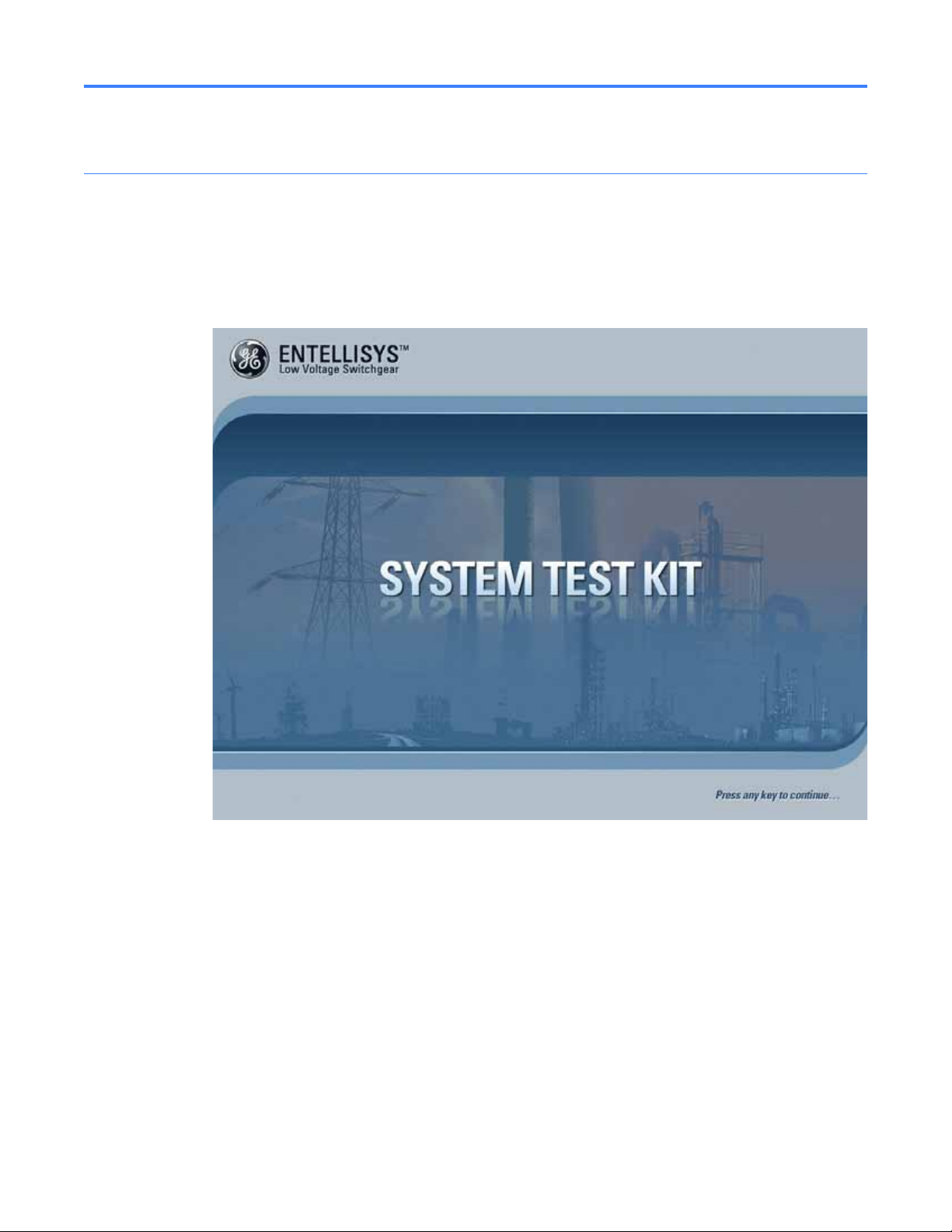
After the test kit boots, the following startup screen will be displayed:
Figure 1-4 Start Up screen
The System Test Kit is kiosked to prevent users from exiting the program and editing the system
files and operating system. This provides added security to protect the system setup.
Press any key to continue.
Getting started 13
Page 13
1.4.2 Self Test
Each time the test kit is powered on, a Self Test is performed to verify the major components are
functioning properly. The following tests are performed:
• Memory test – checks the physical memory in the system. At least 20 MB of free memory
• Hardware configuration – checks the data acquisition card status. Two cards must be
• Test kit setup – checks the setup files and verifies the software and hardware version of the
• Ethernet connectivity – checks the Ethernet connectivity of the system to ensure the System
Figure 1-5 Self-Test screen
must be available after loading the application to ensure the system runs properly.
installed properly and have the proper device number.
test kit.
Configuration Download Link (USB-to-USB Network Bridge) is working properly.
The test kit will display the test being performed on the screen. If any errors are encountered,
the test kit will generate pop-up messages for the user regarding the type of error. Any issues
must be corrected and the unit restarted before continuing. See Troubleshooting
help diagnosing issues.
When the Self Test completes successfully, the Main Menu will be displayed.
System Test Kit14
on page 59 for
Page 14
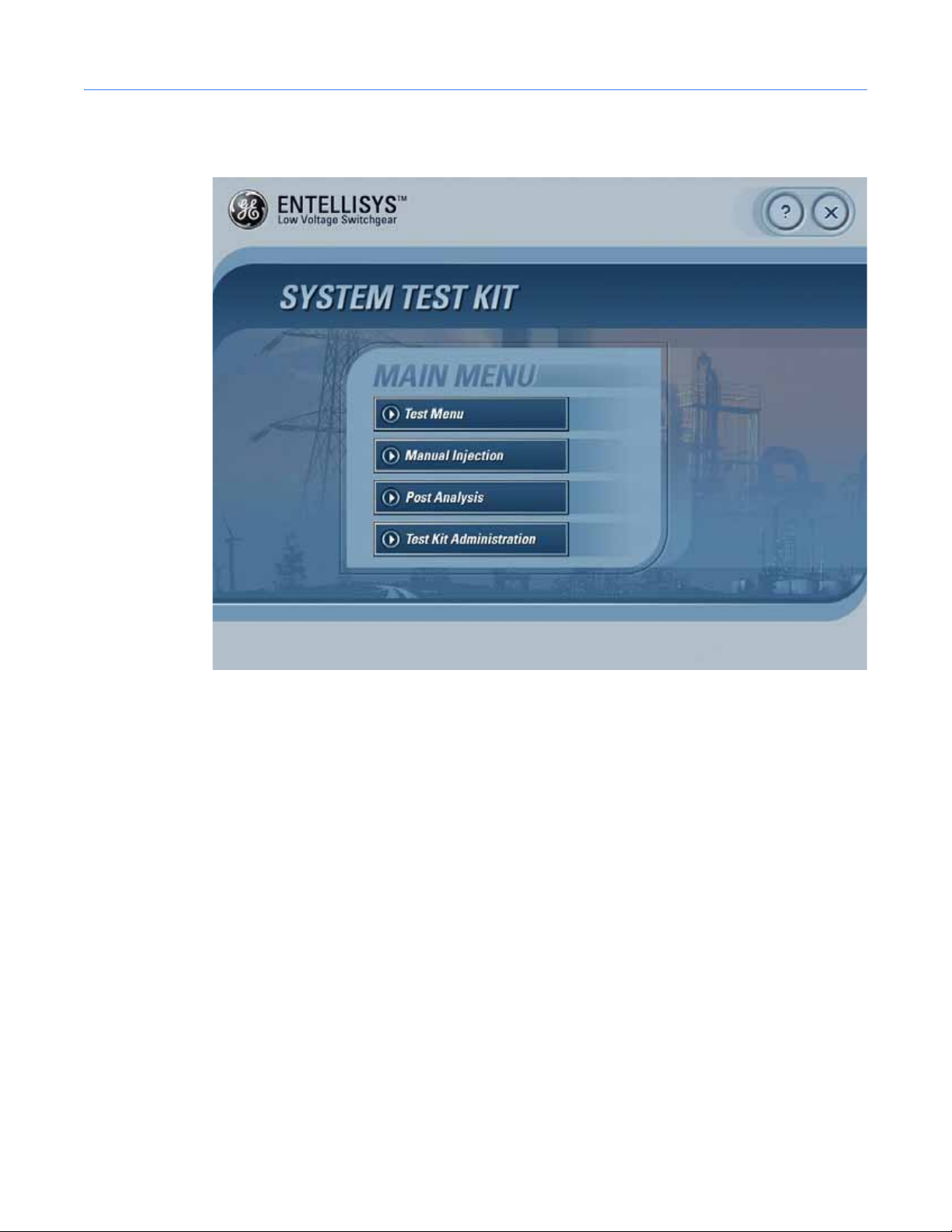
1.4.3 Main Menu
Figure 1-6 Main Menu screen
On the Main Menu, the following choices are provided:
Test Menu
This option lets the user download the settings either from the HMI or from the previously
downloaded settings.
Manual Injection
The Manual Injection screen can be used to inject the signals by manually setting the test kit.
The Manual Injection screen will pop out to accept the settings for the test kit.
Post Analysis
Provides access to the test kit log files for off-line analysis of the test results.
Test Kit Administration
This option allows the user to perform various tasks regarding the test kit setup.
Getting started 15
Page 15

1.4.4 General navigation
X Quit
Quit allows the user to quit from the application and shut down the system.
? Help
Clicking Help provides the user with help on the selected screen.
Tips
Moving the mouse cursor over the control provides tips for that control.
Short Cut Keys
Short cut keys are provided for the following controls:
F1 Pressing F1 will display help
F4 Main Menu
Ctrl F4 Back
F10 Quit the application
1.5 Download switchgear configuration
The test kit requires information about the switchgear lineup under test. For exa mple:
• Circuit breakers by name, for ease of identification
• For each circuit breaker:
• Circuit breaker frame size, CT rating, and PT rating
• Rating switch setting
• Protection options enabled
• Protection elements Pickup and Delay Band Settings
This data provides the operator valid selections when selecting tests, and provides the proper
output levels for the “Pre-Defined” Tests.
Once downloaded, this step can be avoided by using the “Last Download” information—so long
as no configuration or settings have changed.
NOTE: To ensure the test kit has the correct configuration, download the configuration rather
than using the “Last Download”.
System Test Kit16
Page 16
1.5.1 Direct Connect Download from HMI
Select this option to download the System Configuration from the HMI.
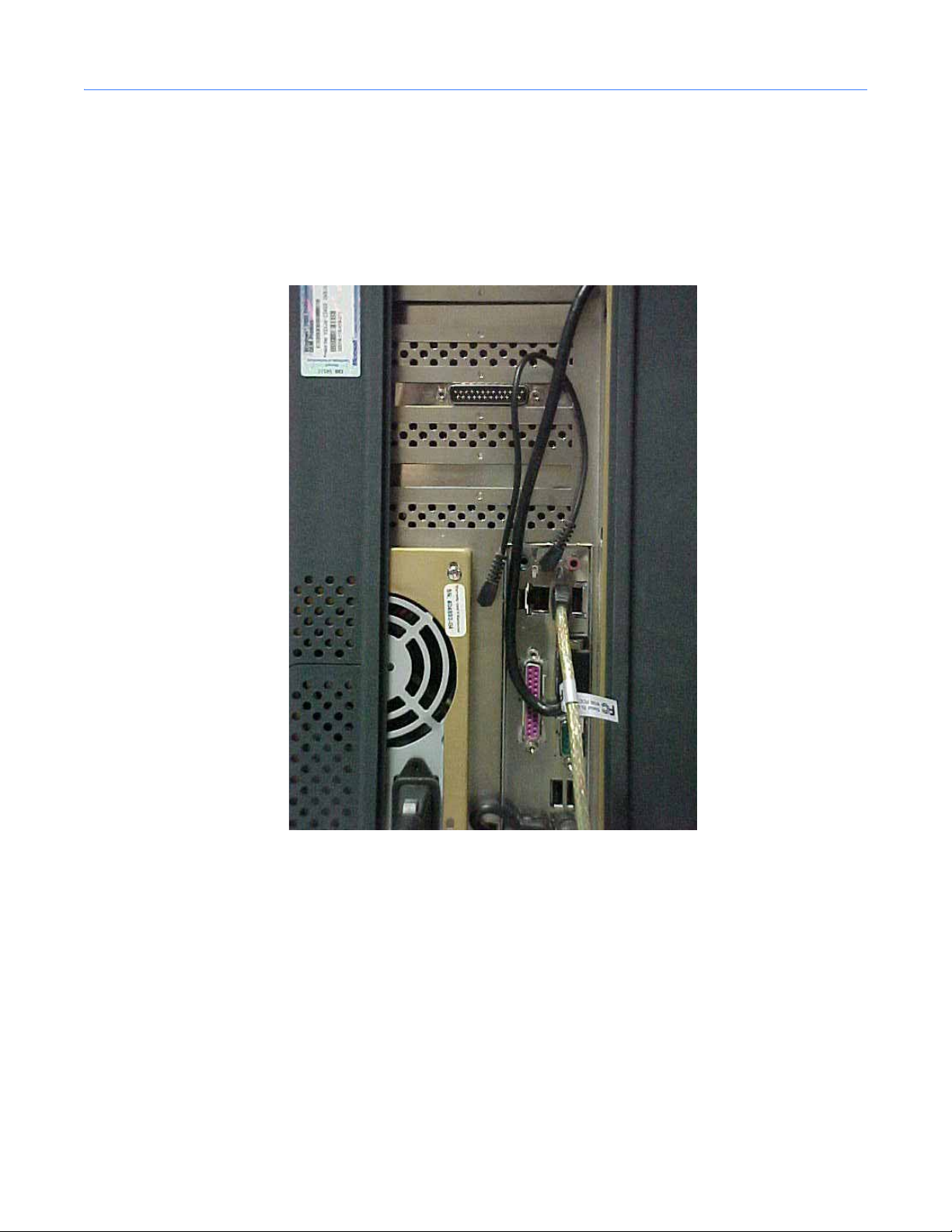
Before proceeding, connect the USB-to-USB cable between the HMI and the test kit. Figure 1-7
shows the USB port on the test kit. Note the white cable. Figure 1-8 shows the USB port on the
HMI. Once the cable is connected, click OK to continue.
Figure 1-7 USB port on test kit
Download switchgear configuration 17
Page 17
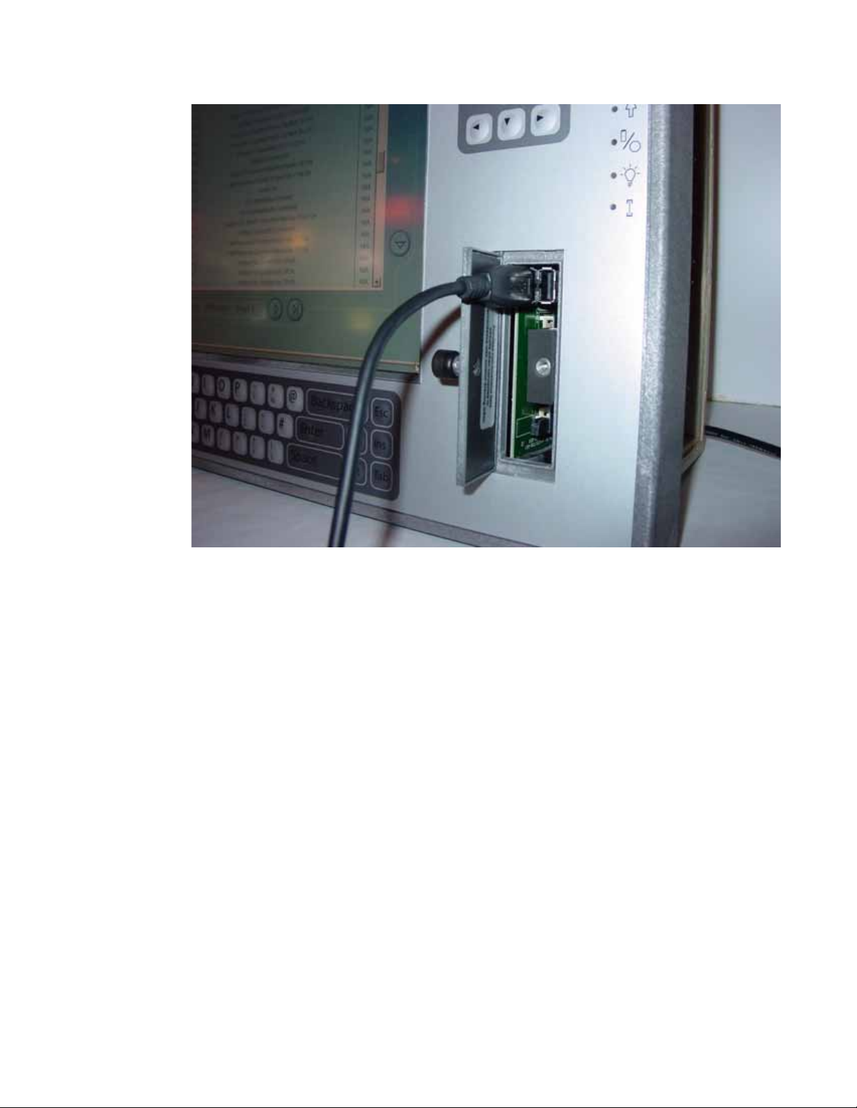
Figure 1-8 USB port on HMI
System Test Kit18
Page 18
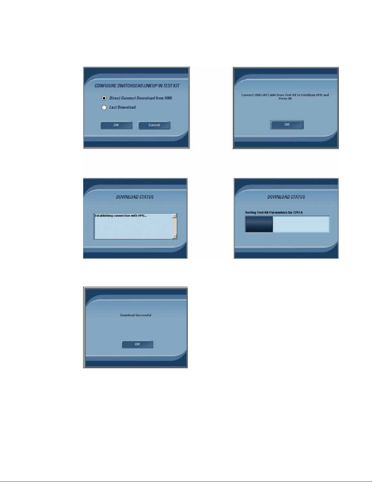
Figure 1-9 shows the screens that will be encountered during the Direct Connect Download
from HMI.
Figure 1-9 Switchgear configuration download process
Download errors will be displayed for the following reasons:
• Settings are not available
• Communications are not established
• Communication is lost
Download switchgear configuration 19
Page 19
1.5.1.1 System Configuration Download Link communication
The test kit communicates with the HMI over the System Configuration Download Link. This link
is a USB-to-USB Network Bridge-Ethernet connection. The IP addresses are programmed by
default into the test kit and the HMI and should not be changed
these IP addresses are mismatched.
• Default HMI USB-to-USB Network Bridge IP address is 192.168.2.50.
• Default test kit USB-to-USB Network Bridge IP address is 192.168.2.25.
The HMI’s IP address must be set in the test kit. To verify this is set properly, from the HMI Setup
screen, go to the Test Kit Administration.
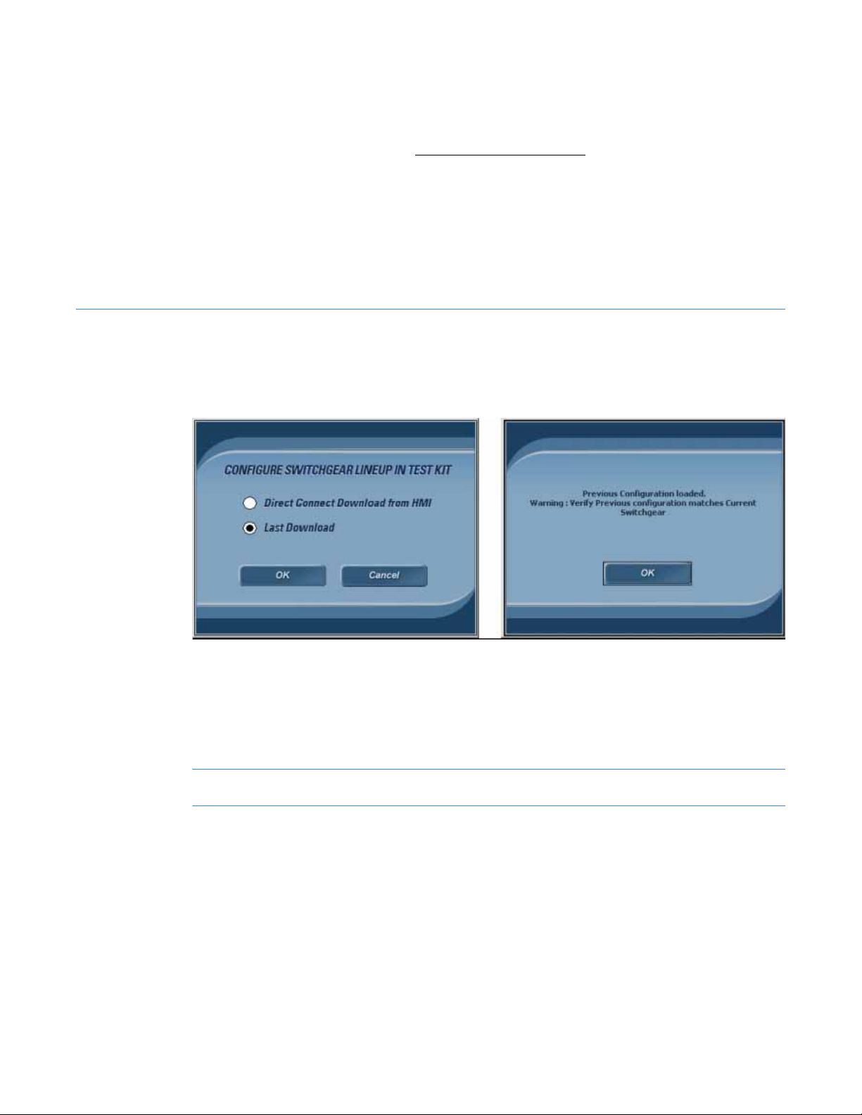
1.5.2 Last Download
Select this option to download the previously downloaded switchgear lineup configuration.
Figure 1-10 Process to download previous settings
. Download failure will result if
Care should be taken before deciding to use previously downloaded settings.
• Is this the same lineup that was downloaded previously?
• Has anything changed since the configuration was downloaded previously?
NOTE: Mismatch in configuration and/or settings will result in incorrect test results.
System Test Kit20
Page 20
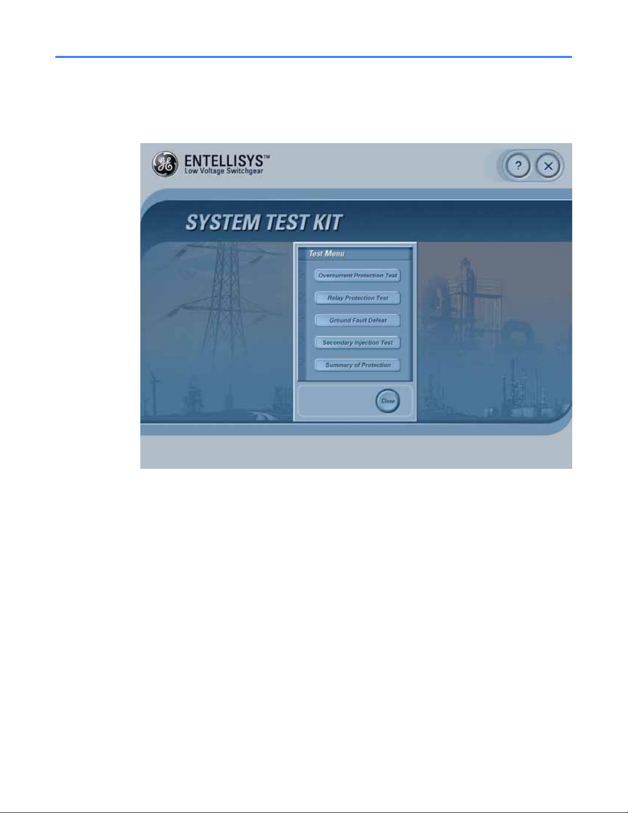
1.6 Test Menu
Once the switchgear configuration has been loaded, the Test Menu will display.
Figure 1-11 Test Menu
Below is a brief description of each of the tests:
Overcurrent Protection Test
Allows operator to perform Overcurrent Protection tests.
Relay Protection Test
Allows operators to perform Relay Protection tests.
Ground Fault Defeat
Allows operator to temporarily Defeat/Disable or Resume Ground Fault protection. This may be
required for Primary or Secondary injection testing outside the test kit.
Secondary Injection Test
Allows operator to temporarily suspend CT Compensation for Secondary Injection testing
outside the test kit.
Summary Of Protection
Provides the protection enabled at each circuit breaker.
Test Menu 21
Page 21

1.6.1 Overcurrent Protection Test
1.6.1.1 Functions
Tests various Overcurrent Protection functions. The functions must be optioned and enabled in
the system to perform the respective tests.
Long Time (LT) Overcurrent Protection
Verifies the long time overcurrent protection function for a circuit breaker in the system. It can
be performed as either a trip or no trip test. To test LT, the test kit injects a sum-of-squares
current value for any phase above the LT pickup setting. The result of the test is a trip time with
an accuracy of 10% of the expected trip time.
Short Time (ST) Overcurrent Protection
Verifies the short time overcurrent protection function for a circuit breaker in the system. The
test can be performed as either a trip or no trip test. To test ST, the test kit injects a
sum-of-squares current value for any phase above the ST pickup setting. The result of the test is
a trip time with an accuracy of 10% of the expected trip time.
Instantaneous (IOC) Overcurrent Protection
Verifies the instantaneous overcurrent protection function for a circuit breaker in the system.
The test can be performed as either a trip or no trip test. To test IOC, the test kit provides an
input current that exceeds the programmed IOC threshold. The result of the test is a trip time
with an accuracy of 10% of the expected trip time.
Ground Fault (GF) Protection
Verifies Ground Fault protection function for a circuit breaker in the system. The test can be
performed as either a trip or no trip test.
In a three-wire system, the test kit will provide three phase currents with vector sum greater
than the pickup threshold.
In a four-wire, WYE-system, the test kit will provide three phase currents and a neutral with
vector sum greater than the pickup threshold.
In either case, the result is a trip time with an accuracy of 10% of the expected trip time.
System Test Kit22
Page 22

1.6.1.2 Test methods
There are three test methods:
• Pre-Defined Test – Uses pre-defined fault levels for the test selected.
• User-Defined – Allows the operator to set fault levels for the test selected.
• Autom atic Trip time Curve Test – Automatic Trip Time Curve will automatically compute the
expected trip time curve for the circuit breaker under test depending on Protection elements
enabled, Rating Switch, and CT rating of the circuit breaker connected. This will then
automatically inject low voltage levels at different test points and graph the curve with
expected and observed tested points.
The test kit requires the actual circuit breaker settings to compute the required fault levels and
expected trip time for the selected protection test. The circuit breaker settings are read by the
test kit during the Switchgear Configuration Download process described in Download
switchgear configuration on page 16.
1.6.1.3 Pre-Defined Overcurrent Protection Test
Tests the various Overcurrent Protection functions using pre-defined fault levels for ease of use.
Figure 1-12 Pre-Defined Over Current Protection Test
Test Menu 23
Page 23

Quick Test Guide
1. Enter Operator Name and Test Description.
2. Select a Circuit Breaker.
3. Select Breaker Trip or No Trip Test.
4. Select Ground Fault Defeat (or not) depending on Fault Phase(s) desired.
5. Select the Test Selection to perform.
6. Select the Fault Phase.
7. Click “Perform Test”.
Test setup field description
Table 1-3 Test setup field description
Test Name Unique test identifier, assigned by the test kit, generated by the type of test
selected and the date the test is performed.
Operator Operator name entered by the Test Operator. (20-character limitation)
Test Description Test description entered by the operator, t o be st ored in the log file.
(150-character limitation)
Breaker Selection Circuit breaker to be tested, selected by the operator.
Compartment # Displays the Compartment number of the circuit breaker selected.
Breaker Trip Specifies whether the test will physically trip the circuit breaker.
; – Circuit breaker will Trip
– Circuit breaker will not Trip
Ground Fault Allows users to temporarily Defeat Ground Fault during the test, or to
Resume/Run Ground Fault as normal during the test. Ground Fault must be
defeated for single phase tests—otherwise a trip on Ground Fault will occur.
; – GF will Resume/Run as Normal.
– GF will be temporarily defeated during the test period.
Note: After the test has concluded, Ground Fault will resume automatically.
This feature is enabled only when Ground Fault is enabled in the selected
circuit breaker.
Breaker Setting Table/Tabs Displays the actual settings for the circuit breaker selected. This is for
information only.
Test Selection Specifies the type of test to perform. Operator selectable.
Only enabled protection functions for the selected circuit breaker are
provided in drop-down.
Pre-Defined Settings Displays the pre-defined fault levels to be injected for the test and circuit
breaker selected. Levels for Prefault, Fault, and Post faults are described in
Table 1-4.
These values are determined with respect to the circuit breaker selected and
its protection settings.
System Test Kit24
Page 24

Table 1-3 Test setup field description
Fault Phase The phase(s) for fault injection. Operator selectable.
Options for LT, ST, IOC Test Selection is: Phase A, Phase B, Phase C, Phase A &
B, Phase B & C, Phase C & A, Phase A, B & C
Option for GF Test Selection: Phase A, Phase B, Phase C, and Neutral
Pre-defined values for Overcurrent Protection tests
Table 1-4 Pre-defined values for Overcurrent Protection tests
Type of Test Prefault
(for all Phases)
Long Time 80.00% of LT Pickup 135.00% of LT Pickup 0% of LTPickup
Short Time 80.00% of ST Pickup 110.00% of ST Pickup 0% of LTPicku p
Instantaneous 80.00% of IOC Pickup 110.00% of IOC pickup 0% of LTPickup
Ground Fault 10% of CT 110.00% of GF Pickup 0% of GF Pickup
Fault
(for selected Phases)
Post Fault
(for all Phases)
Test results
Table 1-5 Test results
Time Stamp Table Provides a time stamp history of the Breaker Status (Open or Closed) and the
Breaker Actuation device involved in the trip (Flux Shifter or Shunt Trip).
Expected Trip Time Expected trip time automatically calculated from the pickup & delay band
settings and circuit breaker clearing time.
Observed Trip Time Observed trip time displayed after the test is performed.
Test Summary LED Specifies the test results by comparing the observed trip time with the expected
trip time.
Green Successful (within +/– 20% of expected time)
Red Unsuccessful
Gray Test Aborted
Test settings and results are saved to the hard drive with the report name as Test Name_Time.
Test Menu 25
Page 25

1.6.1.4 User-Defined Overcurrent Protection test
Provides operators with a more advanced method for Overcurrent Protection testing. Operators
set the Pre-Fault, Fault, and Post-Fault levels for the circuit breaker under test.
Figure 1-13 User-Defined Overcurrent Protection test
Quick Test Guide
1. Enter Operator Name and Test Description.
2. Select a Breaker.
3. Select Breaker Trip or No Trip Test.
4. Select Ground Fault Defeat or Resume depending on Fault Phase(s) desired.
5. Set the required fault levels.
a. Select Level (Pre-Fault, Fault, or Post-Fault).
b. Set the % of CT & Phase Angle for Phase IA, IB, IC, and Neutral.
c. Repeat for each Level.
6. Set the Pre-Fault, Fault, and Post-Fault times.
7. Click Apply to save the test param eters.
8. Click Perform Test.
System Test Kit26
Page 26

Test setup field description
Table 1-6 Test setup field description
Test Name Unique test identifier, assigned by the test kit, generated by the type of test
selected and the date the test is performed.
Operator Operator name entered by the Test Operator. (20-character limitation)
Test Description Test description entered by the operator, t o be stored in the log file.
(150-character limitation)
Breaker Selection Circuit Breaker to be tested, selected by the operator.
Compartment # Compartment number of the circuit breaker selected.
Breaker Trip Specifi es whether or not the test will physically trip the circuit breaker.
; – Circuit Breaker will Trip
– Circuit Breaker will not Trip
Ground Fault Allows users to temporarily Defeat Ground Fault during the test, or to
Resume/Run Ground Fault as normal during the test. Ground Fault must be
defeated for single phase tests—otherwise a trip on Ground Fault will occur.
; – GF will Resume/Run as Normal.
– GF will be temporarily defeated during the test period.
Note: After the test has concluded, Ground Fault will resume automatically.
This feature is enabled only when Ground Fault is enabled in the selected
circuit breaker.
Breaker Setting Table/Tabs Displays the actual settings for the circuit breaker selected. This is for
information only.
Level Allows the user to set the required levels for the corresponding test
(Pre-Fault, Fault, and Post-Fault).
% of CT Percentage of the CT Rating to be injected for a given input (IA, IB, IC, and
optionally Neutral)
Max values:
Pre-Fault: 10% of CT
Fault: 28x CT
Post-Fault: 10% of CT
Phase Angle Phase angle to be injected. (Range between –360° to +360°)
Expected Trip Module Type of trip that should be observed, calculated from the operat or-entered
fault levels.
Expected Trip Time Trip time that should be observed, calculated from the operator-entered
fault levels.
Pre-Fault Time The time duration Pre-Fault levels will be injected from test kit. Operator
selectable.
Test Menu 27
Page 27

Table 1-6 Test setup field description
Fault Time The time Fault levels will be injected. Operator selectable.
Post-Fault Time The time duration Post-Fault levels will be injected. Operator selectable.
User-Defined Test Settings Displays the curr en ts and v o ltage s t hat will b e inj ected, ca lcul ated f r om t he
operator's selections (for the Fault Level currently displayed).
Test results
Prior to a test the “Test Results” button will be grayed out.
After a test is performed, the “Te st Results” button will display. Once pressed, the following is
displayed:
Figure 1-14 Overcurrent Protection Test Results
System Test Kit28
Page 28

Table 1-7 Test results
Level User-Defined Test Settings are displayed separately for each Level
(Pre-Fault, Fault, and Post-Fault). Use the pull-down menu to select the Level
for the corresponding User-Defined Test Settings.
User-Defined Test Settings Summarizes the test settings injected for the level shown.
Test Results Once the test is performed, it displays the time sequence of circuit breaker
status and the device that actuated the circuit breaker (Shunt Trip or Flux
Shifter).
Expected Trip Time Expected trip time automatically calculated from the pickup, delay band
settings, and circuit breaker clearing time.
Observed Trip Time Observed trip time displayed after the test is performed.
Test Summary LED Specifies the test results by comparing the observed trip time with the
expected trip time.
Green Successful (within +/– 20% of expected time)
Red Unsuccessful
Gray Test Aborted
Test settings and results are saved to the hard drive with the report name as Test Name_Time.
1.6.1.5 Automatic Trip Time Curve Test
The automated trip curve test is a test that can automatically verify long time, short time,
instantaneous, and ground fault functions based on the settings (ST, LT, IOC, frame size, etc.).
The test kit will inject signals and measure the amount of time delay before the circuit breaker
trips. It would then compare the timing to the circuit breaker trip-time curve to pass or fail each
protection function. Trip time of the circuit breaker will determine the Pass or Fail for the
protection test. It is a No Trip test that will not trip the circuit breaker.
Test Menu 29
Page 29

Figure 1-15 Automatic trip time curve test
Quick Test Guide
1. Enter Operator Name and Test Description.
2. Select a Breaker.
3. Select Breaker Trip or No Trip Test.
4. Select Ground Fault Defeat or Resume depending on Fault Phase(s) desired.
5. Select the Curve Type.
6. Select the Fault Phase.
7. Click Perform Test.
Test setup field description
Table 1-8 Test setup field description
Test Name Unique test identifier , a ss ig ne d by the test kit, generated by the type of
test selected and the date the test is performed.
Operator Operator name entered by the Test Operator. (20-character limitation)
Test Description Test description entered by the operator, to be stored in the log file.
(150-character limitation )
Breaker Selection Circuit Breaker to be tested, selected by the operator.
Compartment # Compartment number of the circuit breaker selected.
System Test Kit30
Page 30

Table 1-8 Test setup field description
Breaker Trip Specifies whether the test will physically trip the circuit breaker.
; – Circuit Breaker will Trip
– Circuit Breaker will not Trip
Ground Fault Allows users to temporarily Defeat Ground Fault during the test, or to
Resume/Run Ground Fault as normal during the test. Ground Fault must
be defeated for single phase tests—otherwise a trip on Ground Fault will
occur.
; – GF will Resume/Run as Normal.
– GF will be temporarily defeated during the test period.
Note: After the test has concluded, Ground Fault will resume
automatically.
This feature is enabled only when Ground Fault is enabled in the selected
circuit breaker.
Breaker Setting Table/Tabs Displays the actual settings for the circuit breaker selected. This is for
information only.
Select Curve Type Select one of two types of curves to generate—either “Overcurrent Trip
Time Curve” or “Ground Fault Trip Time Curve”. Operator selectable.
Fault Phase The phase(s) for fault injection. Operator selectable.
Options for LT, ST, IOC Test Selection: Phase A, Phase B, Phase C, Phase A &
B, Phase B & C, Phase C & A, Phase A, B & C
Option for GF Test Selection: Phase A, Phase B, Phase C, and Neutral
Automatic Trip Time Settings This table displays the amount of test kit voltages that will be inje cted with
respect to the calculated trip time curve.
How trip time curve generated
For Overcurrent Protection test, three LT Points, three ST points, and two IOC Points are tested
for generating the Automatic Trip time curve. Overcurrent test points are considered as
multiples of LT pickup.
For Ground Fault Protection test, four points are tested when GFI2T curve is enabled and two
points when disabled. Ground Fault test points are considered in multiples of GF pickup.
The setup required for Overcurrent Protection tests is based on Protection bits enabled.
Test Menu 31
Page 31

Test Results
The Test Results tab will be enabled when all the test points are tested. The test kit will display
the Expected, Observed, and the % error in the table.
Figure 1-16 Automatic Trip Time Test results
1.6.2 Relay Protection Test
The Relay Protection Test screen allows the user to perform various tests for Relay protection
functionality based on the options enabled in the syst em. Possible tests are as follows:
• Over Frequency Test
• Under Frequency Test
• Overvoltage Test
• Undervoltage Test
• Phase Lo ss
• Power Reversal
• High Current Alarm
Over Frequency
Sets the frequency above the set point for the specified time delay.
Under Frequency
Sets the frequency below the set point for the specified time delay.
System Test Kit32
Page 32

Overvoltage
Injects a phase voltage greater than the set point for the specified time delay. There are three
options:
• One phase is above the pickup threshold
• Two phases are above the pickup threshold
• Three phases are above the pickup threshold
Undervoltage
Injects a phase voltage less than the set point for the specified time delay. There are three
options:
• One phase is below the pickup threshold
• Two phases are below the pickup threshold
• Three phases are below the pickup threshold
Phase Loss
Injects a negative-phase-sequence voltage greater or less than the nominal 1X value of the
system voltage.
Power Reversal
Injects waveforms that have the direction of the power reversed and the magnitude of the
power greater than the set point for the specified time delay.
High Current Alarm
Injects waveforms that have currents greater than the programmed threshold for a time
greater than the programmed delay to generate high current alarm.
NOTE: For the High Current Alarm test only, the test kit will not be able to provide any Test
Results because the test kit does not receive any feedback from the Messenger. To verify the
results, the operator must check for a High Current Alarm event in the Entellisys HMI, Sequence
of Events screen.
Two test methods are provided for Relay Protection:
• Pre-Defined Test – uses pre-defined fault levels for the test selected.
• User-Defined – allows the operator to set fault levels for the test selected.
Test Menu 33
Page 33

1.6.2.1 Pre Defined Test
Tests the various Relay Protection functions using pre-defined fault levels for ease of use.
Figure 1-17 Pre-Defined Relay Protection Test
Quick Test Guide
1. Enter Operator Name and Test Description.
2. Select a Breaker.
3. Select Breaker Trip or No Trip Test.
4. Select Ground Fault Defeat or Resume depending on Fault Phase(s) desired.
5. Select the Test Selection to perform.
6. Select the Fault Phase.
7. Click Perform Test.
System Test Kit34
Page 34

This screen has the following selections and controls available. A user can perform either trip or
no trip single point protection relay function tests at the Messenger.
Table 1-9 Selecti ons and controls
Test Name Unique test identifier, assigned by the test kit, generated by the type of test
selected and the date the test is performed.
Operator Operator name can be entered here for the Reports. (20-character limitation)
Test Description Operator enters test description to be stored in the log file. (150-character
limitation)
Breaker Trip Specifies whether the test will physically trip the circuit breaker.
; – Circuit Breaker will Trip
– Circuit Breaker will not Trip
Ground Fault Allows users to temporarily Defeat Ground Fault during the test, or to
Resume/Run Ground Fault as normal during the test. G round Fault must be
defeated for single phase tests—otherwise a trip on Ground Fault will occur.
; – GF will Resume/Run as Normal.
– GF will be temporarily defeated during the test period.
Note: After the test has concluded, Ground Fault will resume automatically.
This feature is enabled only when Ground Fault is enabled in the selected
circuit breaker.
Compartment # Switchgear compartment number of the circuit breaker selected for testing.
Breaker Selection The circuit breaker to perform the test.
Test Selection Test Selection will let the type of protection fault be generated.
Breaker Settings Circuit Breaker settings will display the cu rrent sett ings of that se lected circuit
breaker.
Pre-defined Settings This table displays the amount of test kit voltages that will be injected with
respect to the present settings of the selected c ircuit breaker.
Fault Phase Requirement Displays the present Fault Phase Requirement for the selected Relay
protection:
One phase is above the pickup threshold.
Two phases are above the pickup threshold.
Three phases are above the pickup threshold.
Breaker Settings This will display the current circuit breaker settings on which the test will be
performed.
Overvoltage Settings This will display the current overvoltage settings of the system.
Undervoltage Settings This will display the current undervoltage settings of the system.
Over Frequency Settings Over Frequency settings will be displayed depending on the setting from
CCPU.
Test Menu 35
Page 35

Table 1-9 Selecti ons and controls
Under Frequency Settings Under Frequency settings will be displayed depending on the settings from
CCPU.
Phase Loss settings Phase Loss settings will be displayed depending on the settings from CCPU.
Power Reversal Power Reversal settings will be displayed depending on the settings from
CCPU.
High Current High Current Settings will be displayed depending on the settings from CCPU.
Pre-Defined Settings Depending on the current Messenger settings, Selected Level, Phase selected,
Frequency or Multiplier value IA, IB, IC, IN, VA, VB, VC will be calculated and
displayed on the screen.
Test results
Table 1-10 Test results
Time Stamp Table Once the test is performed, it displays the time stamping of circuit breaker
status and the device that actuated the circuit breaker (Flux Shifter or Breaker
Open).
Expected Trip Time Expected trip time automatically calculated from the pickup, delay band
settings, and circuit breaker clearing time.
Observed Trip Time Observed trip time displayed after the test is performed.
Test Summary LED Specifies the test results by comparing the observed trip time with the
expected trip time.
Green Successful (within +/– 20% of expected time)
Red Unsuccessful
Gray Test Aborted
Table 1-11 Default values for pre-defined relay protection tests
Type of Test Prefault Fault Post Fault
Over Frequency System Frequency Pickup *1.01 System Frequency
Under Frequency System Frequency Pickup * 0.99 System Frequency
Overvoltage 100% of PT P ickup * 1.05 96% of PT
Undervoltage 100% of PT Pickup * 0.95 100% of PT
Phase Loss 0% Pickup + 1% 0%
Power Reversal 10 KW Positive Power Pickup * 1.1 Reverse Power 10 KW Positive Power
High Current Pickup * 0.5 Pickup * 1.1 Pickup * 0.5
System Test Kit36
Page 36

Table 1-12 Phase Selectors for pre-defined relay protection test
Type of Test Phases Selected
Over Frequency All Phases
Under Frequency All Phases
Overvoltage Depends on the Phase Requirement in HMI
Undervoltage Depends on the Phase Requirement in HMI
Phase Loss Phase VC
Power Reversal Phase IA, IB, IC
High Current All Phases
1.6.2.2 User Defined Test
This test method allows the operator to change the protection parameters and perform the test
according to the user-intended settings.
Figure 1-18 User-defined Relay Protection Test
Test Menu 37
Page 37

Quick Test Guide
1. Enter Operator Name, and Test Description.
2. Select a Breaker.
3. Select Breaker Trip or No Trip Test.
4. Select Ground Fault Defeat or Resume depending on the test desired.
5. Set the required fault levels:
a. Select Level (Pre-Fault, Fault, or Post-Fault).
b. Set the % Multiplier or KW or Frequency to change the Voltage or Phase or Frequency of
Current signals (IA, IB, IC, & IN) or Voltage signals (VA, VB, VC) based on the selected
protection test.
c. Repeat for each level.
6. Set the Pre-Fault, Fault, and Post-Fault times.
7. Click Apply to save the test param eters.
8. Click Perform Test.
Setup
Table 1-13 Setup
Test Name Unique test identifier, assigned by the test kit, generated by the type of
test selected and the date the test is performed.
Operator Operator name can be entered here for the reports. (20-character
limitation)
Test Description Operator enters test description to be stored in the log file. (150-character
limitation)
Breaker Selection Circuit Breaker selection on which the signals will be injected.
Compartment # Compartment number of the system will be displayed depending on the
circuit breaker selected for testing.
Breaker Trip Specifies whether the test will physically trip the circuit breaker.
; – Circuit Breaker will Trip
– Circuit Breaker will not Trip
Ground Fault Allows users to temporarily Defeat Ground Fault during the test, or to
Resume/Run Ground Fault as normal during the test. Ground Fault must
be defeated for single phase tests—otherwise a trip on Ground Fault will
occur.
; – GF will Resume/Run as Normal.
– GF will be temporarily defeated during the test period.
Note: After the test has concluded, Ground Fault will resume
automatically.
This feature is enabled only when Ground Fault is enabled in the selected
circuit breaker.
System Test Kit38
Page 38

Table 1-13 Setup
Breaker Settings This will display the current circuit breaker settings on which the test will
be performed.
Overvoltage Settings This will display the current overvoltage settings of the system.
Undervoltage Settings This will display the current undervoltage settings of the system.
Over Frequency Settings Over Frequency settings will be displayed depending on the setting from
CCPU.
Under Frequency Settings Under frequency settings will be displayed depending on the settings from
CCPU.
Phase Loss settings Phase Loss settings will be displayed depending on the settings from
CCPU.
Power Reversal Power Reversal settings will be displayed depending on the settings from
CCPU.
High Current High Current Settings will be displayed depending on the settings from
CCPU.
User-defined Settings This table displays the amount of test kit volta ges that will be injected with
respect to the settings made by the operator.
Pre-Fault Time This will be the time set for injecting the set pre-fault values.
Expected Trip Time Trip time is calculated automatically from the pickup and the delay band
settings. Entering Offset timing will prolong the output of the test kit for
that duration.
Post-Fault Time This will be the time set for injecting the set Post-Fault values.
Level Level selection allows the user to set the required levels for the
corresponding test. Based on the selected protection test. Currents IA, IB,
IC, IN or Voltage signals V A, VB, VC along with phase a ngle can be modified
using this selection.
Expected Trip module Expected Trip module will display the type of trip that will happen when
the fault levels for protection test are set.
Test Results Test Results will display the current results after performing the test. This
button will be grayed out if the test is aborted.
Apply Apply will save the current settings to the selected Messenger.
Default Default will set all the curren t s e tt in gs for fault generation to default level s.
Test Menu 39
Page 39

Table 1-14 Default values for user-defined relay protection tests
User-Defined Frequency / Multiplier / KW Range
Prefault Fault Post Fault
Over Frequency 50 Hz – 60 Hz
0.1 Hz increment
Under Frequency 50 Hz – 60 Hz
0.1 Hz increment
Overvoltage 96% to 104%
0.5% increment
Undervoltage 96% to 104%
0.5% increment
Phase Loss 0% to 7%
1% increment
Power Reversal 0 to 100 KW
10 KW increment
High Current 0% to 100%
5% increment
50 Hz – 70 Hz
0.1 Hz increment
44 Hz – 60 Hz
0.1 Hz increment
104% to 132%
0.5% increment
47.5% to 95%
0.5% increment
7% to 51%
1% increment
0 to 1000 KW
10 KW increment
45% to 205%
5% increment
50 Hz – 60 Hz
0.1 Hz increment
50 Hz – 60 Hz
0.1 Hz increment
96% to 104%
0.5% increment
96% to 104%
0.5% increment
0% to 7%
1% increment
0 to 100 KW
10 KW increment
0% to 100%
5% increment
System Test Kit40
Page 40

1.6.2.3 Relay Protection Test Results screen
The Relay Protection Test Results screen will display the results for the tests performed using
the user-defined tests.
Figure 1-19 Relay protection test results screen
Table 1-15 Selections and controls
Level Select the fault level to display the test settings.
User-Defined Test Settings Summarizes the test performed at the level shown.
Test Results Once the test is performed, it displays the time sequence of circuit breaker
status and the device that actuated the circuit breaker (Shunt Trip or Flux
Shifter).
Expected Trip Time Expected trip time automatically calculated from the pickup, delay b and
settings, and beaker clearing time.
Observed Trip Time Observed trip time displayed after the test is performed.
Test Summary LED Specifies the test results by comparing the observed trip time with the
expected trip time.
Green Successful (within +/– 20% of expected time)
Red Unsuccessful
Gray Test Aborted
Test settings and results are saved to the hard-drive with the report name as TestNumber_Time.
Test Menu 41
Page 41

1.7 Ground Fault Defeat
Performing single phase tests may unintentionally trigger a Ground Fault trip in circuit breakers
with Ground Fault protection enabled. This may not be desired when testing other protection
functions (e.g., short time, single phase test).
The Ground fault defeat screen allows the operator to “Defeat” or suspend Ground Fault
protection temporarily for external Secondary or Primary Injection—single phase testing
without Ground Fault trips.
Only circuit breakers with Ground Fault enabled are eligible for this. If GF is disabled, the Breaker
and selection box will be grayed out.
NOTE: The test kit connector must be attached to the desired Messenger/circuit breaker to
defeat Ground Fault.
Once the test connector is removed from the Messenger, the Ground Fault protection function
resumes as normal.
Figure 1-20 Ground fault defeat screen
System Test Kit42
Page 42

1.7.1 Setup
Circuit Breaker Name ; Resume GF will Resume/Run as normal.
Circuit Breaker Name Defeat GF will be temporarily defeated for the circuit breaker
specif ied while the test kit's test connector is physically
connected to the Messenger.
Ground Fault Defeat 43
Page 43

1.8 Summary of Protection
The Summary of Protection screen displays the list of circuit breakers in the system. Also
displayed are the protection elements enabled for each circuit breaker to be used as a
reference for the operator. The test kit will not allow tests for a protection function that is not
enabled.
Figure 1-21 Summary of Protection
System Test Kit44
Page 44

1.9 Manual Breaker Injection
The Manual Breaker Injection feature allows the operator to inject currents and v oltages without
knowledge of the Switchgear conf iguration.
Operators must enter the configuration of the circuit breaker under test and must calculate the
levels required to generate the expected trip conditions.
NOTE: This feature is for the advanced operator who knows the configuration of the circuit
breaker under test, and knows what levels to inject to test the desired protection functions.
Figure 1-22 Manual Breaker Injection
Quick Test Guide
1. Select the Frame Rating of the circuit breaker.
2. Select the CT rating.
3. Select the Rating Switch.
4. Select the PT rating of the system.
5. Enter the Test Description.
6. Enter the Operator name.
7. Select the Breaker Selection for Trip or Not Trip operation.
Manual Breaker Injection 45
Page 45

1.9.1 Setup
8. Select the Ground Fault Defeat or Resume depending on the Fault Level test required.
9. Enter the Frequency of the test kit output.
10. Enter the Breaker connection Forward or Reverse direction.
11. Enter the desired Voltage and Phase angle for Voltage phases.
12. Enter the desired Current and Phase angle for Current phases.
13. Enter the Test time for the test signals to be injected.
14. Press Perform test to perform the test.
Table 1-16 Setup
Frame Rating Select Frame Rating.
CT Rating Select CT Rating.
Rating Switch Select Rating Switch.
PT Rating Select PT Rating.
Test Name Unique test identifier, assigned by the test kit, generated by the type of
test selected and the date the test is performed.
Test Description Lets the user enter the Test Description (150-character limitation)
Operator Let the user enter the operator name (20-character limitation)
Breaker Trip Specifies whether the test will physically trip the circuit breaker.
; – Circuit Breaker will Trip
– Circuit Breaker will not Trip
Ground Fault Allows users to temporarily Defeat Ground Fault during the test , or t o
Resume/Run Ground Fault as normal during the test. Ground Fault
must be defeated for single phase tests—otherwise a trip on Ground
Fault will occur.
; – GF will Resume/Run as Normal.
– GF will be temporarily defeated during the test period.
Note: After the test has concluded, Ground Fault will resume
automatically.
This feature is enabled only when Ground Fault is enabled in the
selected circuit breaker.
Maximum Test Voltage Displays Maximum Test Voltage that can be set for testing from
Manual Injection.
Maximum Test Current Displays Maximum Test Current that can be set for testing from
Manual Injection.
System Test Kit46
Page 46

Table 1-16 Setup
Frequency Frequency of the Signal to be injected.
Breaker Connection Flow current Forward / Reverse connected circuit breakers.
Voltage Inputs Inputs for Voltage Phases.
Current Inputs Inputs for Current phases.
Test Settings for Fault Generation Display of Current and Voltage settings.
Test Results Once the test is performed, it displays the time stamping of circuit
breaker status and the device that actuated the circuit breaker (Flux
Shifter or Breaker Open).
Test Time Time entry for test kit execution.
1.9.2 Manual circuit breaker injection input range
Table 1-17 Manual circuit breaker injection input range
Parameter Range
Voltage 0 to 2x PT Rating Volts
Current 0 to 28x CT Rating Amps
Phase Angle –360° to +360°
Test Time 0.5 to 17000 secs
Manual Breaker Injection 47
Page 47

1.10 Post Analysis Selection screen
The Post Analysis feature allows users to analyze test results.
Users can generate reports and save to a USB Memory Stick. The reports are in HTML format.
NOTE: Upon exiting the Post Analysis screen, the USB drive will automatically eject. Users must
re-insert the USB Memory stick before generating the next report.
1.11 Test Reports
System Test Kit Reports can be generated from the Post Analysis screen. Depending on the type
of test for which the reports are generated, the output settings will change in the report.
All the reports are HTML reports and it will be generated on the USB Memory stick.
Following are the fields available in the Test Reports:
Table 1-18 Fields available in the test reports
General Test Information
Test Name Uniquely identified test kit-assigned name.
Operator Name Operator name that was entered while performing test.
Test Description Description of the test entered during testing.
Breaker Settings Displays the circuit breaker settings depending on the type of test for which
the report was generated. See Table 1-19 for the protection settings that will
display with respect to the test.
Breaker Name Name of the circuit breaker under test.
Compartment # Compartme nt number of the circuit breaker.
Frame Rating Prints the Frame rating of the circuit breaker.
CT Rating Prints the CT rating of the circuit breaker.
Rating Switch Prints the Rating switch value.
PT Rating Outputs the PT rating value.
Test Settings
Pre-Fault Settings All the Pre-Fault settings will be reported.
Fault Settings All the Fault settings that were injected during Fault time will be displayed.
Post-Fault Settings All the Post-Fault settings that were injected during post-fault time will
display.
System Test Kit48
Page 48

Table 1-18 Fields available in the test reports
Test Results
Trip Time Information Displays all the Trip time Information.
Pre-Fault Time Time for which the Pre-Fault signals are injected.
Expected Trip time Expected trip time for the test.
Post-Fault Time Time for which the Post-Fault signals are injected.
Observed Trip time Observed Trip time for the test.
Digital Input Time Stamping Time Stamping for Digital inputs.
Comments Comments that are entered by the user while generating reports.
Prepared by This is an empty field given for the operator to manually sign after report
generation.
Date Date is the report generated date.
Circuit Breaker Settings in report for Protection Test
Table 1-19 Circuit Breaker settings in report for Protection Test
LT Protection Test
Pickup setting Long time pickup setting.
Delay setting Delay band setting.
Short Time Protection Test
Status ST Protection enabled or disabled condition.
Pickup Setting Pickup setting of Short time protection.
I2T Status Inverse trip time enabled status.
Delay setting Delay setting of Short time protection.
Ground fault
Status GF Protection Enabled or Disabled condition.
Pickup Setting Pickup setting of Short time protection.
I2T Status Inverse trip time enabled status.
Delay setting Delay setting of Short time protection.
IOC Protection Test
Status Enabled or Disa bled status of the IOC Protection.
Pickup Setting Pickup setting of IOC.
Test Reports 49
Page 49

Table 1-19 Circuit Breaker settings in report for Protection Test
Over Frequency
Status Protection enabled condition.
Pickup Setting Pic kup Setting of the OF protection.
Delay Setting Prints Delay Setting of OF protection.
Under Frequency
Status Protection enabled condition.
Pickup Setting Pic kup Setting of the UF protection.
Delay Setting Prints Delay Setting of UF protection.
Overvoltage
Status Protection enabled condition.
Pickup Setting Pickup Setting of the OV protection.
Delay Setting Prints Delay Setting of OV protection.
Undervoltage
Status Protection enabled condition.
Pickup Setting Pickup Setting of the PL protection.
Delay Setting Prints Delay Setting of PL protection.
I2T Inverse Trip time enabled or disabled for Undervoltage protection.
Phase Loss
Status Protection enabled condition.
Pickup Setting Pickup Setting of the PL protection.
Delay Setting Prints Delay Setting of PL Protection.
Power Reversal
Status Protection enabled condition.
Pickup Setting Pic kup Setting of the PR protection.
Delay Setting Prints Delay Setting of PR protection.
System Test Kit50
Page 50

1.12 Test kit administration
Figure 1-23 Administration menu
Test kit administration 51
Page 51

1.12.1 HMI setup
The test kit communicates with the Entellisys Low Voltage HMI to download system
configuration, preventing the operator from entering it manually.
A USB-to-USB cable, running a peer-to-peer network communication bridge, is used between
the test kit and the HMI for communication. Both the HMI and test kit have dedicated LAN
connections enabled for this. The test kit must know the HMI IP address. These IP addresses
have been pre-set and should not be changed.
In the event the addresses must be changed, this screen provides the ability to enter the HMI
USB-to-USB Network Communication Bridge IP address.
NOTE: For most systems the HMI IP address for the USB-to-USB bridge should remain at the
default setting of 192.168.2.50. Modify this setting only if it was changed in the HMI.
Figure 1-24 HMI Setup screen
Enter the IP address in the X.X .X.X format, where X = 0 to 255. The maximum value that can be
entered is 255.255.255.255.
System Test Kit52
Page 52

1.12.2 Disk cleanup
This option enables operators to delete unwanted test reports from the System Test Kit. This
should be done periodically to prevent the hard drive from filling up.
NOTE: It is recommended to have at least 50,000 KB of free space at all times.
Figure 1-25 Disk cleanup screen
List of Files – displays the test reports available in the test kit.
To select files:
• Click an individual file.
• Press Shift to select multiple files.
• Or click Select All to select all files.
Delete File – prompts the operator with a confirmation to delete the selected files. The Delete
File button will be grayed out if no files are selected.
Test kit administration 53
Page 53

1.12.3 System Information
This function displays the hardware version and data acquisition card information for the
hardware present in the test kit. It is provided for technical support information only.
Figure 1-26 System Information screen
System Test Kit54
Page 54

1.12.4 Test Kit Validation Test
This feature provides internal tests to validate the test kit hardware.
Figure 1-27 Test Kit Validation screen
1.12.4.1 Customer Validation Tests
These tests are provided for the customer to validate the test kit hardware. The pre-set tests
check both the analog output and the digital output signals.
To perform tests
1. Remove the “Test Kit Output Connector” from the Messenger.
2. Press Perform Test.
NOTE: Remove the test kit connector from the Messenger during Test Kit Validation tests to
prevent false results and to prevent test signals from being injected into the Messenger.
Test Results
The results are summed up in the two LED indicators on the left-hand side of the screen.
• Green = Pass (indicating the hardware is working properly).
• Red = Failure (indicating there is a hardware problem). More detailed data is available on the
left-hand side. For any failures, contact GE Post Sales Service for technical help (see How to
contact us on page 2).
Test kit administration 55
Page 55

1.12.4.2 Factory Test only
The Factory Tests are provided for factory personnel only and should not be performed by
customers. This test requires special production test hardware and will fail without the proper
equipment.
NOTE: Remove the test kit connector from the Messenger during factory test kit validation
tests to prevent false results and to prevent test signals from being injected into the Messenger.
1.13 Long-term maintenance
The following preventative maintenance is recommended for the long-term care of your test kit.
• Keep the system in a cool, dry, and dust-free environment.
• Power ON the system at least once every 3 months to recharge the CMOS battery.
• Make sure the system is OFF whenever it is shifted from one place to another.
1.13.1 Motherboard battery maintenance
The CMOS or Complementary Metal Oxide Semiconductor battery is an on-board
semiconductor chip. This chip is used to store system information and configuration settings
while the computer is off and on.
Lifetime: The standard lifetime of a CMOS battery is around 10 Years, however this amount of
time can change depending on the use and environment that the computer resides.
Detection: A Low battery can be detected by checking the time stamping of test results. See
Troubleshooting
Corrective action
• Replace the CMOS battery. Follow the manufacturer’s instructions for proper battery
disposal.
• Make sure that the polarity of the batt ery is right before inserting inside the slot.
• Reload the saved CMOS Setup Details. (There are no special settings for the System Test Kit,
so this step can be skipped.)
on page 59 for help diagnosing the issues.
System Test Kit56
Page 56

Figure 1-28 CMOS battery on motherboard
1.13.2 Test kit care
The following outlines tips for taking good care of your test instrument.
1.13.2.1 Handling the test kit
Make sure that the keyboard assembly is properly closed onto the SAX before transporting it.
This will ensure you do not lose the keyboard as well as protecting the LCD screen. The handle is
located securely to the strongest part of the machine and distributes the load of the SAX evenly
to allow easy carriage and proper balance.
1.13.2.2 Cables
All cables should be treated with care. Do not over extend any cable as this could result in
internal breakage in the cable. It is essential that the cable and its plug be handled in the proper
manner without force.
1.13.2.3 Power
Always make sure the power cord is in top condition before using them with the SAX. Make sure
the power source is reliable and of proper standard. The power supply is capable of handling
100-240 V and 50-60 Hz. Do not use on an already overloaded circuit.
Long-term maintenance 57
Page 57

1.13.2.4 Cleaning the LCD screen
• Do not use cleaner that contains alcohol.
• Do not use cloth that could be abrasive to the surface of the LCD.
• Always gently wipe the LCD surface when cleaning.
Do not use any abrasive material to scratch the LCD screen, as they can leave marks on the
surface. Do not apply any pressure to the surface of the LCD screen either with objects or
hands; this will ensure that the screen do not suffer from internal damage or cracks.
1.13.2.5 Cleaning the keyboard
• Do not spill any liquid on to the keyboard.
• Do not drop particles into the spacing between keys.
• Use a compressed air cleaner to remove the dust within the keyboard.
The keyboard is essential in that it helps protect the LCD during tra nsportation. Avoid liquid spills
or small objects entering the keyboard. The touch pad surface should be kept dry and clean.
1.13.2.6 Cleaning the fan filter
• Remove the filter from its housing.
• Use a compressed air cleaner to blow off the dust from the filter.
If necessary, wash the filter material and dry completely before reinserting it.
System Test Kit58
Page 58

1.14 Troubleshooting
Table 1-20 Troubleshooting
Error Potential Cause Suggest ed Fix
Main Menu—Test Menu and
Manual Injection Button grayed
out
Self Test Error—Memory Failure Correct the Physical Memory
Self Test Error—Hardware
Configuration Error
Self Test Error—Test Kit Setup Invalid File Setting requires
Self Test Error—Ethernet
Connectivity
When there is a problem in the
Power DAQ driver or with the
Hardware cards, these buttons will
not be available to inject signals
from the test kit.
problem and restart the machine.
Problem in Hardware
Wrong Power DAQ drivers
reinstallation of test kit software.
Mismatch in the installed software
and hardware versions.
Cable not connected. Verify USB cable is connected to
Check System information i n the
Test Kit administration.
Contact GE Post Sales Service for
technical support (see How to
contact us onpage2).
Have User Administrator check
physical memory space. Or, send
unit for repair.
Contact GE Post Sales Service for
technical support (see How to
contact us onpage2).
Check System information i n the
Test Kit administration.
Contact GE Post Sales Service for
technical support (see How to
contact us onpage2).
Check System information i n the
Test Kit administration.
Contact GE Post Sales Service for
technical support (see How to
contact us onpage2).
both the System Test Kit and the
HMI.
Download Switchgear
Configuration from HMI
Error Msg—“Download Failed.
Check the USB cable and verify
the IP address configuration of
HMI and System Test Kit”
HMI USB-to-USB Network Bridget
IPAddress is not set properly in the
test ki t.
Verify USB port enabled. Requires User Admin to log onto
Cable not connected. Verify USB cable is connected to
Verify the address in Test Kit
Administration, HMI Setup. Default
address is 192.168.2.50, which
matches the HMI setup. Only in rar e
cases should this be changed. See
DEH-230 Entellisys Low Voltage
Switchgear System Administrator
Manual for details.
unit.
both the System Test Kit and the
HMI.
Troubleshooting 59
Page 59

Table 1-20 Troubleshooting
Error Potential Cause Suggest ed Fix
HMI IP Address incorrect. Check the HMI IP address in HMI
Setup, under the Test Kit
Administration. This should be the
same IP address as set in the HMI
(by default, HMI IP address is set at
192.168.2.50).
Download from HMI failed due to
improper access/non availability
of settings f ile
Error Msg—No Files are available
for retrieving. Check/Connect
USB cable and verify the
IP address of HMI and System
Test Kit for a new download.
Error Msg—Default CPU is not
Commissioned. Please check and
try again.
Error Msg—No breakers Available
for testing
Communication failed between HMI
and test kit. Note: This download
should only be done between
In-Gear or Near-Gear touchscreen
HMIs (and not remote HMIs).
The test kit uses a f ixed User,
ELVSTESTKIT to login to the HMI.
Make sure the user is still set up in
the test kit and the HMI, with the
same passwords and administrator
rights.
Problem in Settings files of HMI. Improper User access from test kit
to HMI.
Missing or No Settings files in HMI
for download.
There are no valid previous settings
available.
The settings must be downloaded
from the HMI.
Contact GE Post Sales Support for
help (see How to contact us
on page 2).
Configuration downloaded
successfully, but there are no
Call GE Post Sales Support for hel p
(see How to contact us on page2).
commissioned Messengers/circuit
breakers available for testing.
Test Menu
Current Protection Test is grayed
out
No Frame or CT Rating is configured
for the commissioned circuit
breakers.
Relay Protection Test is grayed
out
None of the relay protection
functions are optioned in the
Relay protection functions must be
purchased separately from GE.
system.
Relay protection functions may be
optioned, but they are all disabled in
Enable the protection functions in
the HMI, User Settings Menu.
Settings.
No Frame and CT Rating is
configured.
System Test Kit60
Check for Frame and CT
configurations.
Page 60

Table 1-20 Troubleshooting
Error Potential Cause Suggest ed Fix
GF Defeat Button is grayed out Ground Fault protection is disabled
in all the circuit breakers.
OverCurrent Test
Pre-Defined Overcurrent TestShort Time
/Instantaneous/Ground F ault
Protection elements not optioned
and/or enabled for the circuit
breaker selected.
feature grayed out in Test
Selection in pre-defined tests
Incorrect Switchgear Configuration
used?
Observed trip time reads zero Test cable not connected to either
the test kit or the EntelliGuard
Messenger.
User-Defined Mode—Trip module
displa ys as No trip
Depending on the type of system
purchased, GF may be enabled in
the HMI under User Settings or it
may need to be optioned in the
Compartment ID Button. Contact GE
for details.
Verify that the Protection enabled
for that circuit breaker in system
based on Table1-4.
Check if settings downloaded were
same as in HMI.
Verify the test kit connector is
attached to the desired circuit
breaker.
Verify that the fault current entered
is greater than any of the LT/ST/IOC
Pickups.
User-Defined
Test has not been run yet.
Overcurrent—% Test Results
button grayed out
Test was aborted.
Pre-Defined Overcurrent
Test has not been run yet.
Protection—Test Summary is
grayed out
Test was aborted.
Automatic Trip Time
Curve—Ground Fault curve
Ground fault is not enabled fo r the
selected circuit breaker.
feature grayed out in select curve
type
% Error is displayed as 100 Verify that the System Test Kit cable
is connected to the selected circuit
breaker on which the test is
performed and that observed trip
time is not zero.
% Error is displayed as ___ Verify that the point tested is IOC
trip and that trip time is less than
50/60 ms.
Troubleshooting 61
Page 61

Table 1-20 Troubleshooting
Error Potential Cause Suggest ed Fix
T ime Stamp is incorrect • System time is incorrect.
• Potential problem with CMOS
battery on computer
motherboard.
• To check system time, pul l up
the task bar by moving the
mouse at the bottom of the
screen (or press CTRL - ESC to
open the task bar). Double-click
the clock to view or reset
system time.
• Change CMOS Battery. Details in
Section 1.14.1.
System Test Kit62
Page 62

A Definition of terms
The terms listed and defined are displayed in the Test K i t and are used throughout this guide.
Table A-21 Definition of terms
Term Definition
ATT Automatic Trip Time Test.
CT Current Transformer—a sensor that measures current. There are normally 3 CTs, one
for each phase, and an optional neutral CT.
CT Compensation The system is designed to compen sate for particular characteristics of the CTs used
in the Entellisys System in order to improve accuracy. If a user is testing the system
through secondary injection (input into the CT inp uts of th e EntelliGuard Messenger),
then the unique compensation algorithm must be disabled or test results will be
incorrect.
CT Rating Rating of connected Current Transformer for that circuit breaker.
DAQ Data Acquisitio n
Fault/Fault Level The period of time and/or the voltage current condition during a fault.
Flux Shifter One of two means to actuate the circuit breaker. The flux shifter is used to open (and
lockout) the circuit breaker when the CPU or EntelliGuard Messenger issues a trip
signal.
Frame Rating Frame Size or Rating of the Circuit Breaker.
GF Ground Fault overcurrent protection function
GF Defeat Some tests like single phase tests, will trigger GF trips unintentionally. Therefore, it
may be desirable to disable or defeat GF temporarily during these tests.
HC High Current Alarm protection function
HMI Human Machine Interface
IOC Instantaneous overcurrent protection function
LT Long Time overcurrent protection function
Manual Breaker
Injection
NAN Not a number—error message that gets displayed.
No Trip Test A test that does not cause the circuit breaker to trip
User must manually setup the circuit breaker configuration and power line
characteristics to be injected into the system. Might be desired for a quick test.
OF Over frequency relay protection function
OV Overvoltage relay protection function
63
Page 63

Table A-21 Definition of terms
Term Definition
Phase or Phase Angle Phase angle rotation that can be set from test kit. Range of Phase angle is –360° to
+360°.
PL Phase Loss relay protection function
Post-Fault / Post-Fault
The period of time or the voltage/current condition following a fault.
Level
PR Power Reversal relay protection function
Pre-Fault / Pre-Fault
The period of time and/or the voltage/current condition preceding a fault.
Level
PT Rating Rating of Potential Transformer of the circuit breaker.
Rating Switch Rating switch value of the circuit breaker.
RMS Root Mean Square—calculation used to measure voltage or current .
Secondary Injection Current (and voltage) injection into the system through the CT (and PT) connections
of the EntelliGuard Messenger.
Shunt Trip One of two means to actuate the circuit breaker . Shunt trip is used to open the circuit
breaker when users manually open the circuit breaker from the HMI.
ST Short Time overcurrent protection function
Trip Test A test that causes the circuit breaker to trip
Trip T ime Curve Trip time curve of the connected circuit breaker for different protection schemes.
UF Under frequency relay protection function
USB Universal Serial Bus
UV Undervoltage relay protection function
Definition of terms64
Page 64

 Loading...