

Page 1
GE Consumer & Industrial
Electrical Distribution
AF-650 GP
TM
& AF-600 FP
OPCEIP EtherNet/IP
Operating Instructions
TM
Page 2

Contents
OPCEIP EtherNet/IP
1 Safety
Safety Note 3
Safety Regulations 3
Warning against Unintended Start 4
2 Introduction
About this Manual 5
Technical Overview 5
Assumptions 5
Hardware 5
Background Knowledge 5
ODVA Conformance 6
Abbreviations 6
3 How to Install
Installation 7
The EtherNet/IP Option 7
How to Install Option in Frequency Converter 8
3
5
7
LED Behaviour 9
Topology 10
Network 11
Recommended Design Rules 12
EMC Precautions 13
4 How to Configure
IP Settings 15
Ethernet Link Parameters 16
Configuring the Scanner 17
IP traffic 19
5 How to Control
I/O Assembly Instances 21
EtherNet/IP Connections 22
Class 1 connection 22
Class 3 connection 23
Unconnected Messages, UCMM 23
15
21
Control Word Profile 23
Change of State, COS 24
GE Drive Control Profile 25
GE Drive Control Profile 25
Status Word according to (STW) 27
1
Page 3

OPCEIP EtherNet/IP
ODVA Control Profile 27
Control Word under Instances 20/70 and 21/71 28
Status Word under Instances 20/70 and 21/71 29
Reference Handling 29
Bus Speed Reference Value under Instances 100-101-103/150-151-153 29
Bus Speed Reference Value under Instances 20/70 and 21/71 31
6 Parameters
Parameter Group O-## 33
Parameter Group EN-## 37
O-## Options/Comms 45
EN-## EtherNet 46
Data Types 47
Data Types Supported by AF-650 GP/AF-600 FP 47
7 Troubleshooting
Step-by-step Troubleshooting 49
Alarm Word and Warning Word 49
8 Appendix
Supported CIP Objects 55
33
49
55
2
Page 4
OPCEIP EtherNet/IP
1 Safety
1.1.1 Copyright, Limitation of Liability and Revision Rights
This publication contains information proprietary to GE. By accepting and using this manual the user agrees that the information contained herein will be used
solely for operating equipment from GE or equipment from other vendors provided that such equipment is intended for communication with GE equipment over
an Ethernet serial communication link. This publication is protected under the Copyright laws of Denmark and most other countries.
GE does not guarantee that a software program produced according to the guidelines provided in this manual will function properly in every physical, hard-
ware or software environment.
Although GE has tested and reviewed the documentation within this manual, GE makes no warranty or representation, either express or implied, with respect to
this documentation, including its quality, performance, or fitness for a particular purpose.
In no event shall GE be liable for direct, indirect, special, incidental, or consequential damages arising out of the use, or the inability to use information contained
in this manual, even if advised of the possibility of such damages. In particular, GE is not responsible for any costs including but not limited to those incurred as
a result of lost profits or revenue, loss or damage of equipment, loss of computer programs, loss of data, the costs to substitute these, or any claims by third
parties.
GE reserves the right to revise this publication at any time and to make changes in its contents without prior notice or any obligation to notify previous users of
such revisions or changes.
1
1.1.2 Safety Note
The voltage of the frequency converter is dangerous whenever connected to mains. Incorrect installation of the motor, frequency converter
or network may cause damage to the equipment, serious personal injury or death. Consequently, the instructions in this manual, as well as
national and local rules and safety regulations, must be complied with.
1.1.3 Safety Regulations
1. The frequency converter must be disconnected from mains if repair work is to be carried out. Check that the mains supply has been disconnected and
that the necessary time has passed before removing motor and mains plugs.
2. The [OFF] key on the Keypad of the frequency converter does not disconnect the equipment from mains and is thus not to be used as a safety switch.
3. Correct protective earthing or grounding of the equipment must be established, the user must be protected against supply voltage, and the motor must
be protected against overload in accordance with applicable national and local regulations.
4. The earth leakage currents are higher than 3.5 mA.
5. Protection against motor overload is not included in the factory setting. If this function is desired, set par. to data value Electronic Thermal Overload
trip or data value Electronic Thermal Overload warning.
NB!
The function is initialised at 1.16 x rated motor current and rated motor frequency. For the North American market; the Electronic Thermal Overload functions
provide class 20 motor overload protection in accordance with NEC.
6. Do not remove the plugs for the motor and mains supply while the frequency converter is connected to mains. Check that the mains supply has been
disconnected and that the necessary time has passed before removing motor and mains plugs.
7. Please note that the frequency converter has more voltage inputs than L1, L2 and L3, when load sharing (linking of DC intermediate circuit) and external
24 V DC have been installed. Check that all voltage inputs have been disconnected and that the necessary time has passed before commencing repair
work.
3
Page 5

1.1.4 Warning against Unintended Start
OPCEIP EtherNet/IP
1
1. The motor can be brought to a stop by means of digital commands, bus commands, references or a local stop, while the frequency converter is connected
to mains. If personal safety considerations make it necessary to ensure that no unintended start occurs, these stop functions are not sufficient.
2. While parameters are being changed, the motor may start. Consequently, the [OFF] key must always be activated.
3. A motor that has been stopped may start if faults occur in the electronics of the frequency converter, or if a temporary overload or a fault in the supply
mains or the motor connection ceases.
Touching the electrical parts may be fatal - even after the equipment has been disconnected from mains.
Also make sure that other voltage inputs have been disconnected, such as external 24 V DC, load sharing (linkage of DC intermediate circuit), as well as the motor
connection for kinetic back up.
Please take note of discharge times and further safety guidelines from the section: “Safety and conformity”, in the respective Design Guide (MG.33.Ax.yy).
4
Page 6

2Introduction
2.1.1 About this Manual
OPCEIP EtherNet/IP
First time users can obtain the most essential information for quick installation and set-up in these chapters:
Introduction
How to Install
How to Configure the System
For more detailed information including the full range of set-up options and diagnosis tools please refer to the chapters:
How to Configure the System
How to Control the AF-650 GP/AF-600 FP
How to Access AF-650 GP/AF-600 FP Parameters
Parameters
Troubleshooting
Terminology:
In this manual several terms for Ethernet is used.
- EtherNet/IP, is the term used to describe the CIP/ODVA application protocol.
-Ethernet, is a common term used to describe the physical layer of the network and does not relate to the application protocol.
2.1.2 Technical Overview
EtherNet/IP™ was introduced in 2001 and today is the most developed, proven and complete industrial Ethernet network solution available for manufacturing
™
automation. EtherNet/IP is a member of a family of networks that implements the Common Industrial Protocol (CIP
comprehensive suite of messages and services for a variety of manufacturing automation applications, including control, safety, synchronization, motion,
configuration and information. As a truly media-independent protocol that is supported by hundreds of vendors from around the world, CIP provides users with
unified communication architecture throughout the manufacturing enterprise.
) at its upper layers. CIP encompasses a
2
EtherNet/IP provides users with the network tools to deploy standard Ethernet technology for manufacturing applications while enabling Internet and enterprise
connectivity.
2.1.3 Assumptions
These operating instructions are under the conditions that the GE EtherNet/IP option is used in conjunction with a GE AF-650 GPor AF-600 FP frequency converter,
inclusive that the installed controller supports the interfaces described in this document and that all the requirements stipulated in the controller, as well as the
frequency converter, are strictly observed along with all limitations herein.
2.1.4 Hardware
This manual relates to the EtherNet/IP option OPCEIP, type no. 130B1119 (un-coated) and 130B1219 (coated).
2.1.5 Background Knowledge
The GE EtherNet/IP Option Card is designed to communicate with any system complying with the CIP EtherNet/IP standard. Familiarity with this technology is
assumed. Issues regarding hardware or software produced by other manufacturers, including commissioning tools, are beyond the scope of this manual, and
are not the responsibility of GE.
For information regarding commissioning tools, or communication to a non-GE node, please consult the appropriate manuals.
5
Page 7

2.1.6 ODVA Conformance
The EtherNet/IP option is tested to conform to the ODVA standards, and is certified, towards conformance test level version 3.
2
2.1.7 Abbreviations
Abbreviation Definition
API Actual Packet Interval
CC Control Card
CIP Common Industrial Protocol
CTW Control Word
DHCP Dynamic Host Configuration Protocol
EIP EtherNet/IP
EMC Electromagnetic Compatibility
I/O Input/Output
IP Internet Protocol
LED Light Emitting Diode
LSB Least Significant Bit
MAR Major Recoverable fail
MAU Major Unrecoverable fail
MAV Main Actual Value (actual output)
MSB Most Significant Bit
MRV Main Reference Value
N/A Not applicable
ODVA Open DeviceNet Vendor Association
PC Personal Computer
PLC Programmable Logic Controller
PNU Parameter Number
REF Reference (= MRV)
RTC Real Time Clock
STP Spanning tree Protocol
STW Status Word
OPCEIP EtherNet/IP
6
Page 8
3 How to Install
3.1 Installation
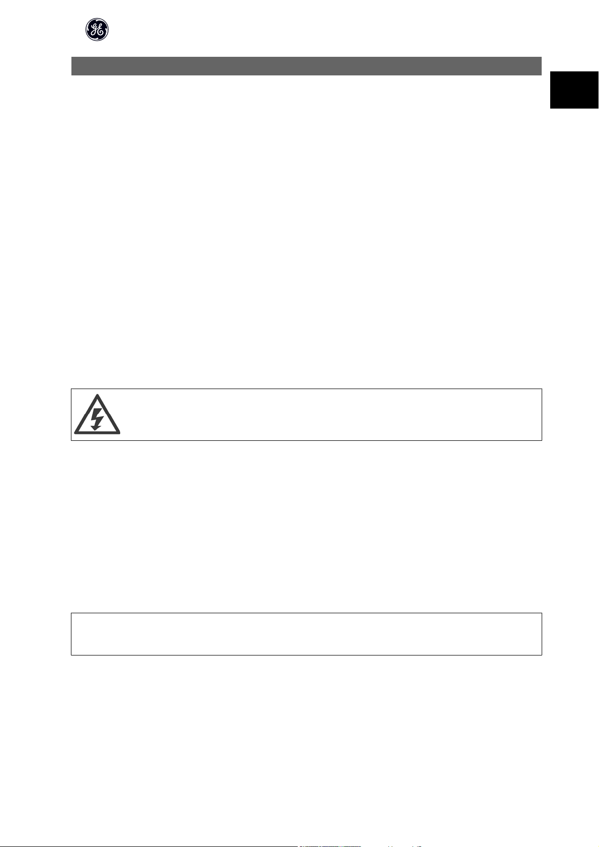
3.1.1 The EtherNet/IP Option
OCPEIP
. .
OPCEIP EtherNet/IP
3
/
Illustration 3.1: Overview of the option
7
Page 9
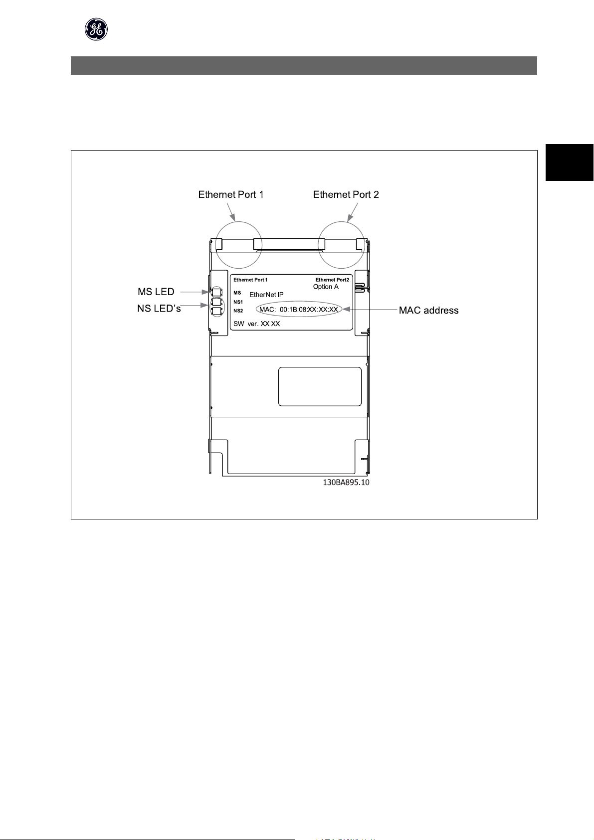
3.1.2 How to Install Option in Frequency Converter
Items required for installing a network option in the frequency converter:
- The network option
- Network option adaptor frame for the AF-650 GP/AF-600 FP. This frame is deeper than the standard frame, to allow space for the network option beneath
- Strain relief (only for unit sizes 11 and 12)
3
OPCEIP EtherNet/IP
Instructions:
- Remove Keypad panel from the AF-650 GP/AF-600 FP.
- Remove the frame located beneath and discard it.
- Push the option into place. The Ethernet connectors must be facing upwards.
- Remove both knock-outs on the network option adaptor frame.
- Push the network option adaptor frame for the AF-650 GP/AF-600 FP into place.
- Replace the Keypad and attach cable
NB!
Do not strip the Ethernet cable and ground it via the strain relief-plate! The grounding of screened Ethernet cable is done through the RJ-45 connector on the
option.
NB!
After installing the OPCEIP option, be aware of the following parameter settings:
par. O-01 Control Site: [2] Controlword only or [0] Digital and ctrl. word
par.O-02 Control Word Source: [3] Option A
8
Page 10

3.1.3 LED Behaviour
The option has 3 bi-coloured LEDs according to ODVA specifications:
OPCEIP EtherNet/IP
Red:
Green:
Description
Flashing red/green The EIP option is in self-test mode
The device does not have a valid IP-address (or is
un-powered)
There are no established CIP connections to the de-
vice
There is established (at least) one CIP connection to
the device
The IP-address assigned to the device is already in
use
LED Label
MS Module Status
NS1 Network Status Ethernet Port 1
NS2 Network Status Ethernet Port 2
The option LED’s operates according to ODVA specifications.
State LED Description
No power Off The device is un-powered
Device operational Green: Solid green The device is operational
Standby Green: Flashing green The device needs commissioning
Minor fault Red: Flashing red The device has detected a recoverable fault
Major fault Red: Solid red The device has detected an un-recoverable fault
Self test
Table 3.1: MS: Module Status
State LED Description
No IP-address (no power) Off
No connections Green: Flashing green
Connected Green: Solid green
Connection time-out Red: Flashing red One or more CIP connections have timed-out
Duplicate IP Red: Solid red
3
Red:
Self test
Green
Table 3.2: NS1 + NS2: Network Status (one per port)
During normal operation the MS and at least one NS LED will show a constant green light.
Flashing red/green The EIP option is in self-test mode
9
Page 11
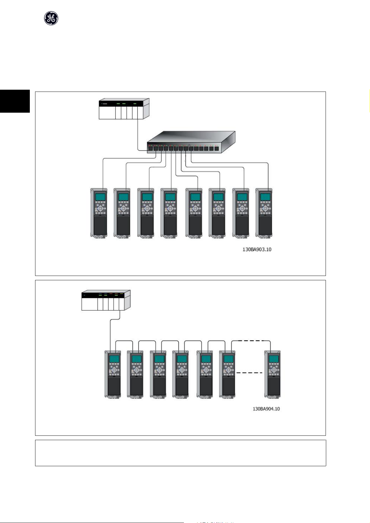
3.1.4 Topology
The OPCEIP features a build-i n Ethernet-switch, thus having two Ethernet RJ-45 connectors. This enables the possibility for connecting several EtherNet/IP options
in a line topology as an alternative to the typical star-topology.
The two ports are equal, in the sense that they are transparent for the option. If only one connector is used, either port can be used.
3
OPCEIP EtherNet/IP
Illustration 3.2: Star topology
Illustration 3.3: Line topology
NB!
For line topology please refer to section: “Recommended design rules” In a line topology all drives must be powered, either by mains or by their 24 V DC option
cards, for the build-in switch to work.
10
Page 12
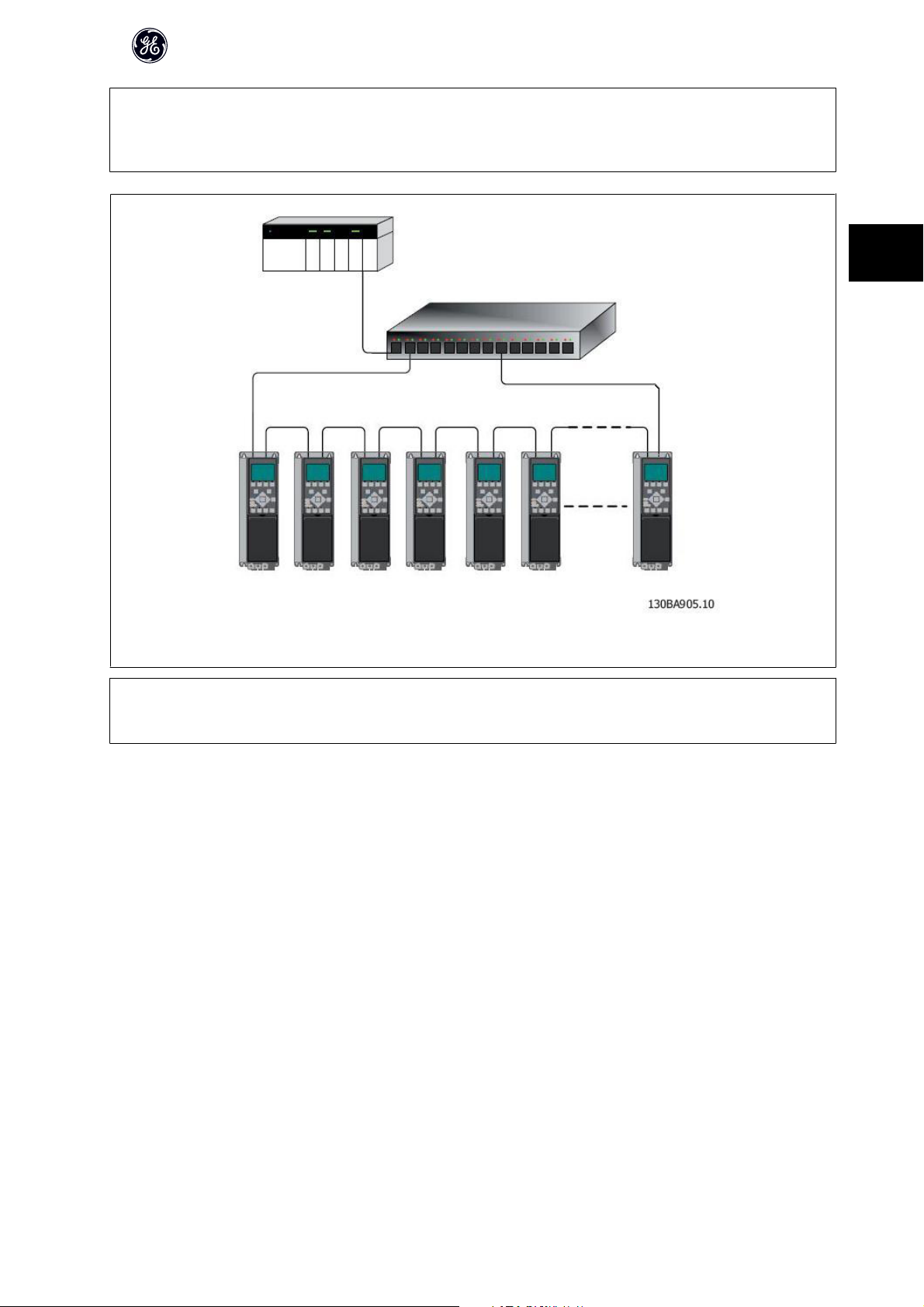
NB!
Please observe that mounting drives of different power-sizes in a line topology may result in unwanted power-off behaviour.
Smaller drives discharge faster than bigger drives. This can result in loss of link in the line topology, which may lead to control word timeout.
To avoid this, mount the drives with the longest discharge time first in the line topology.
OPCEIP EtherNet/IP
3
Illustration 3.4: Ring/redundant line topology
NB!
For this type of topology it is crucial that the network switch supports Spanning Tree Protocol (STP), and that STP is enabled. For more information on Spanning
Tree please refer to section IP traffic.
3.1.5 Network
It is of high importance that the media chosen for Ethernet data transmission are suitable. Usually CAT 5e and 6 cables are recommended for industrial applications.
Both types of cable are available as Unshielded Twisted Pair and Shielded Twisted Pair. Generally shielded cables are recommended for use in industrial envi-
ronments and with frequency converters.
A maximum cable-length of 100 m is allowed between switches.
Optical fibres can be used for gapping longer distances and providing galvanic isolation.
For connecting EtherNet/IP devices both hubs a nd switches can be used. It is, however, recommended always to use suitable industrial graded Ethernet switches.
For more information regarding IP-switching, please refer to section: IP Traffic in this manual.
11
Page 13
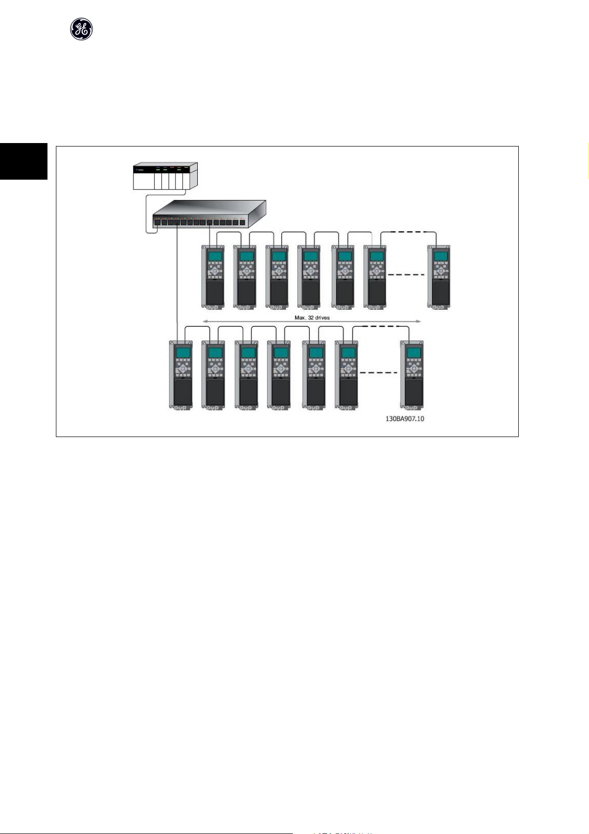
3.1.6 Recommended Design Rules
While designing Ethernet networks special attention and caution must be taken regarding active network components.
While designing a network for line topology it is important to notice that a small delay is added with each every switch in the line.
It is not recommended to connect more than 32 drives in a line at any API. Exceeding the recommended design rules, may result in failing communication.
3
OPCEIP EtherNet/IP
12
Page 14
OPCEIP EtherNet/IP
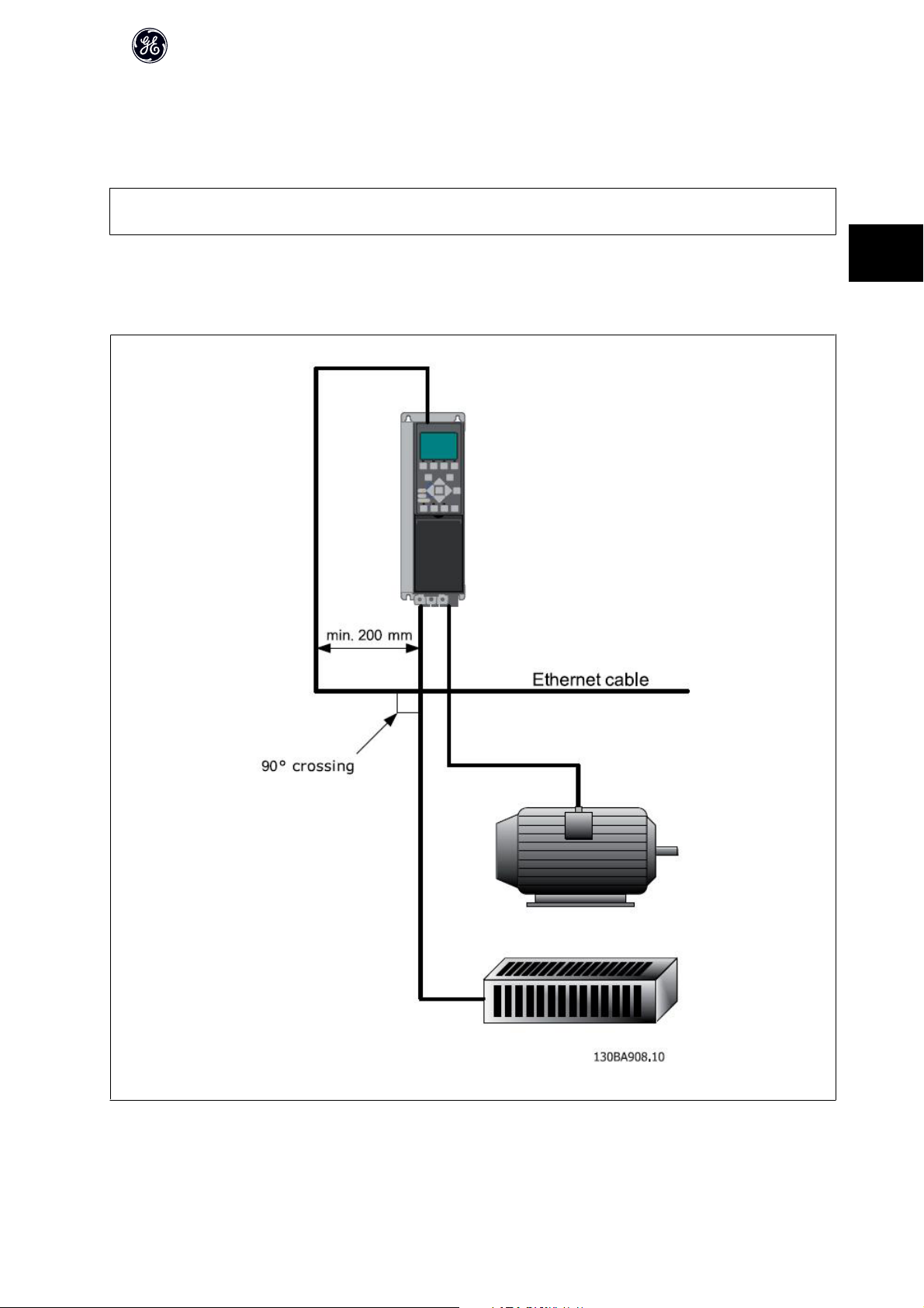
3.1.7 EMC Precautions
The following EMC precautions are recommended in order to achieve interference-free operation of the Ethernet network. Additional EMC information is available
in the AF-650 GP/AF-600 FP series Design Guide.
NB!
Relevant national and local regulations, for example regarding protective earth connection, must be observed.
The Ethernet communication cable must be kept away from motor and brake resistor cables to avoid coupling of high frequency noise from one cable to the
other. Normally a distance of 200 mm (8 inches) is sufficient, but maintaining the greatest possible distance between the cables is recommended, especially where
cables run in parallel over long distances. When crossing is unavoidable, the Ethernet cable must cross motor and brake resistor cables at an angle of 90 degrees.
3
13
Page 15

4
OPCEIP EtherNet/IP
14
Page 16

4 How to Configure
4.1.1 IP Settings
All IP-related parameters are located in parameter group EN-##:
EN-00 IP Address Assignment
EN-01 IP Address
EN-02 Subnet Mask
EN-03 Default Gateway
EN-04 DHCP Server
EN-05 Lease Expires
EN-06 Name Servers
EN-07 Domain Name
EN-08 Host Name
EN-09 Physical Address
The OPCEIP option offers several ways of IP address assignment.
Setting up drive with manual assigned IP address:
OPCEIP EtherNet/IP
4
Par. Name Value
EN-00 IP Address Assignment [0] MANUAL
EN-01 IP Address 192.168.0.xxx*
EN-02 Subnet Mask 255.255.255.0*
EN-03 Default Gateway optional
*= Class C IP address example. Any valid IP address can be entered.
NB!
A power-cycle is necessary after setting the IP parameters manually.
Setting up drive with automatic (BOOTP/DHCP) assigned IP address:
Par. Name Value
EN-00 IP Address Assignment [1] DHCP/[2] BOOTP
EN-01 IP Address Read only
EN-02 Subnet Mask Read only
EN-03 Default Gateway Read only
By IP address assigned by DHCP/BOOTP server, the assigned IP Address and Subnet Mask can be read out in par. EN-01 and EN-02. In par. EN-04 DHCP Server,
the IP address of the found DHCP or BOOTP server is displayed. For DHCP only: The remaining lease-time can be read-out in par. EN-05 Lease Expires.
Par. EN-09, Physical Address reads out the MAC address of option, which is also printed on the label of the option. If using fixed leases together with DHCP or
BOOTP, the physical MAC address is linked with a fixed IP address.
NB!
If no DHCP or BOOTP reply has been received after 4 attempts (e.g. if the DHCP/BOOTP server has been powered off), the option will fallback to the last good
known IP address.
15
Page 17

OPCEIP EtherNet/IP
Par. EN-03, Default Gateway is optional and only used in routed networks.
Par. EN-06, Name Servers
Par. EN-07, Domain Name
Par. EN-08, Host Name
Are used with Domain Name Server systems and are all optional. If DHCP or BOOTP is selected as IP address assignment, these parameters are read only.
NB!
It is only possible to assign valid class A, B and C IP address to the option. The valid ranges are shown in the below table:
4
Class A 1.0.0.1 - 126.255.255.254
Class B 128.1.0.1 - 191.255.255.254
Class C 192.0.1.1 - 223.255.254.254
4.1.2 Ethernet Link Parameters
Parameter group EN-1# holds information Ethernet Link information:
EN-10 Link Status
EN-11 Link Duration
EN-12 Auto Negotiation
EN-13 Link Speed
EN-14 Link Duplex
Please note the Ethernet Link Parameters are unique per port.
Par. EN-10, Link Status and par. EN-11, Link Duration displays information on the link status, per port.
Par. EN-10, Link Status will display Link or No Link according to the status of the present port.
Par. EN-11, Link Duration will display the duration of the link on the present port. If the link is broken the counter will be reset.
Par. EN-12, Auto Negotiation – is a feature that enables two connected Ethernet devices to choose common transmission parameters, such as speed and duplex
mode. In this process, the connected devices first share their capabilities as for these parameters and then choose the fastest transmission mode they both
support.
By default this function is enabled.
Incapability between the connected devices, may lead to decreased communication performance.
To prevent this, Auto Negotiation can be disabled.
If par. EN-12 is set to OFF, link speed and duplex mode can be configured manually in par. EN-13 and EN-14.
Par. EN-12, Link Speed – displays/sets the link speed per port. “None” is displayed if no link is present.
Par. EN-14, Link Duplex – displays/sets the duplex mode per port.
Half-duplex provides communication in both directions, but only in one direction at a time (not simultaneously).
Full-duplex allows communication in both directions, and unlike half-duplex, allows for this to happen simultaneously.
16
Page 18
OPCEIP EtherNet/IP
4.1.3 Configuring the Scanner
EDS file
GE provides a generic English EDS (Electronic Data Sheet) file covering all voltage and power sizes, for off-line configuration.
The EDS file can be downloaded from:
www.geelectrical.com/drives
NB!
The current version of the major EtherNet/IP configuration tools does not support EDS-files for EtherNet/IP devices.
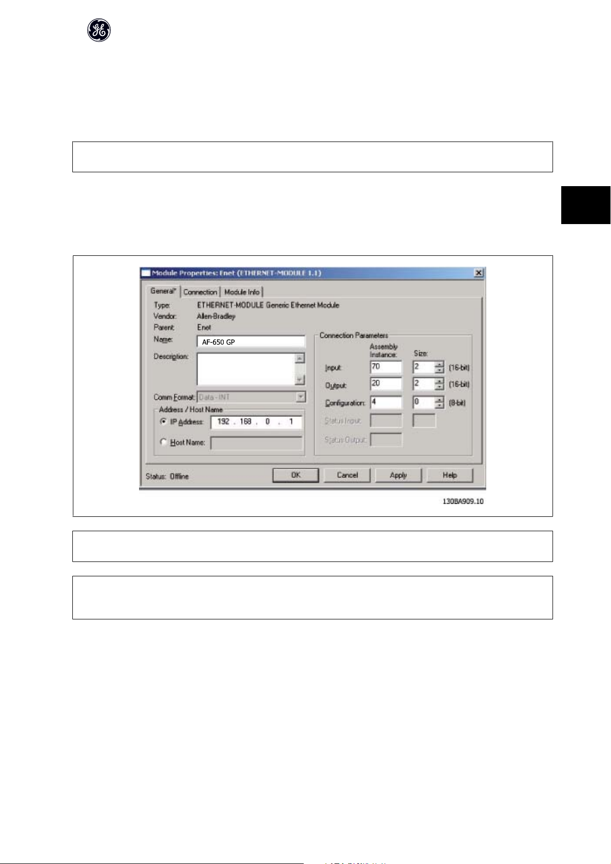
Configuring a Rockwell Master
For configuring a AF-650 GP/AF-600 FP with OCPEIP for operation with a Rockwell (Allen-Bradley) Scanner via EtherNet/IP, the AF-650 GP must be added as a
Generic Ethernet Module.
Under the General-tab, enter information about: Name of device, IP Address,
Assembly Instance and Data size
4
NB!
Under Configuration in the Connection Parameters a “4” must be entered as Assembly Instance.
NB!
Please note that the example shows a 20/70 assembly instance connection. This requires to be set to: ODVA.
Other supported connections are shown in section: I/O Assembly Instanced.
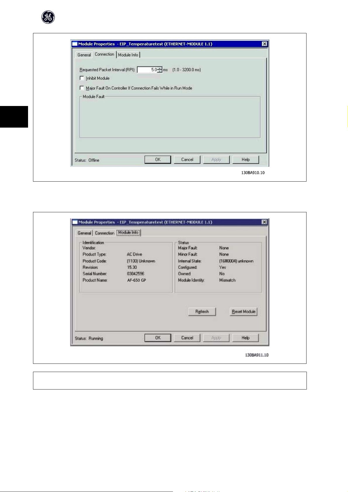
Under the Connection-tab, enter information about: RII and fault conditions.
17
Page 19
4
OPCEIP EtherNet/IP
The Module Info – This tap holds generic information.
The Reset Module – This button will make a simulated Power-cycle of the drive.
NB!
For more information on the CIP class 1 Forward Open command, please refer to section: EtherNet/IP Connections under the How to Control -chapter.
18
Page 20

OPCEIP EtherNet/IP
4.1.4 IP traffic
The use of Ethernet based network for industrial automation purposes, calls for careful and thorough network design. Especially the use of active network
components like switches and routers requires detailed know-how about the behaviour of IP traffic.
Some important issues:
Multicast
Multicast traffic; is traffic that is addressed to a number of recipients. Each host processes the received multicast packet to determine if it is the target for the
packet. If not, the IP package is discarded. This causes an excessive network load of each node in the network since they are flooded with multicast packages.
The nature of EtherNet/IP traffic is that all Originator-to-Target traffic is Unicast (point-to-point) but Target-to-Originator traffic is optional Multicast. This enables
that several listen only -connections can be made to a single host.
In switched networks hosts also have the risk of becoming flooded with multicast traffic. A switch usually forwards traffic by MAC address tables build by looking
into the source address field of all the frames it receives.
A multicast MAC address is never used as a source address for a packet. Such addresses do not appear in the MAC address table, and the switch has no method
for learning them, so it will just forward all multicast traffic to all connected hosts.
IGMP
IGMP (Internet Group Management Protocol) is an integrated part of IP. It allows hosts to join or leave a multicast host group. Group membership information is
exchanged between a specific host and the nearest multicast router.
For EtherNet/IP networks it is essential that the switches used, supports IGMP Snooping. IGMP Snooping enables the switch to “listen in" on the IGMP conversation
between hosts and routers. By doing this the switch will recognise which hosts are members of which groups, thus being able to forward multicast traffic only to
the appropriate hosts.
Spanning Tree Protocol (STP)
For an Ethernet network to function properly, only one active path can exist between two nodes. Spanning-Tree Protocol is a link management protocol that
provides path redundancy while preventing undesirable loops in the network.
When loops occur, some switches see stations appear on both sides of it self. This condition confuses the forwarding algorithm and allows for duplicate frames
to be forwarded.
To provide path redundancy, Spanning-Tree Protocol defines a tree that spans all switches in an extended network. Spanning-Tree Protocol forces certain
redundant data paths into a standby (blocked) state. If one network segment in the Spanning-Tree Protocol becomes unreachable, or if Spanning-Tree Protocol
costs change, the spanning-tree algorithm reconfigures the spanning-tree topology and re-establishes the link by activating the standby path.
Spanning-Tree Protocol operation is necessary if the AF-650 GPor AF-600 FP’s are running in a ring/redundant line topology.
4
19
Page 21

5
OPCEIP EtherNet/IP
20
Page 22

5How to Control
5.1 How to Control
5.1.1 I/O Assembly Instances
I/O Assembly Instances are a number of defined process control objects with defined content comprising control and status information.
Unlike DeviceNet it is possible to run with asymmetrical instances. E.g. 101/153 = 8 bytes/20 bytes.
It is not possible to mix instances across profiles, e.g. 20/100. Assembly instances must be consistent to the: ODVA or Drive profile.
The controlling instance can be read in par. EN-20, Control Instance.
OPCEIP EtherNet/IP
The figure below shows the I/O Assembly Instance options for controlling and monitoring the AF-650 GP/AF-600 FP drive.
Profile
(par.O-10 Control Word
Profile)
ODVA
Direction
Originator →Target
Target →Originator
Instances
(decimal)
20 4
21 4
70 4
71 4
100 4
Size
(bytes)
Data
CTW
(Drive)
CTW
Originator →Target
101 8
(Drive)
5
Drive
Target →Originator
103 20
150 4
151 8
153 20
CTW
(Drive)
STW
(Drive)
STW
(Drive)
130BA920.10
STW
(Drive)
21
Page 23

NB!
Use of 32-bit process data.
For configuration of a 2-word (32-bit) parameter read/write, use 2 consecutive arrays in par. EN-21 and EN-22, like [2]+[3], [4]+[5], [6]+[7] etc. Read/write of 2-
word values in arrays like: [3]+[4], [5]+[6], [7]+[8] are not possible.
5.1.2 EtherNet/IP Connections
The OPCEIP option supports the CIP connections described in the following sections:
5.1.3 Class 1 connection
I/O connection using TCP transport. Maximum one Class 1 connection is supported by the EtherNet/IP option, but several listen only connection can be established
5
if multicast is selected as Transport type. This type of connection is used for cyclic I/O and Change-Of-State connections. The connection is established with a
Forward Open command, containing the following information:
Transport Type:
Specified for both directions:
- Originator-to-Target / Target-to-Originator.
- Point to Point
- Multicast (Target-to-Originator only)
Data Size:
Specified (in bytes) for both directions: Originator -> Target / Target -> Originator.
The data-size depends on the assembly-instance chosen in: Destination.
OPCEIP EtherNet/IP
Instances (decimal) Data Size
Originator →Target Target →Originator
20, 21, 100 70, 71, 150 4 bytes
101 151 8 bytes
103 153 20 bytes
Packet Rate:
Specified (in milliseconds) for both directions: Originator -> Target / Target -> Originator.
Minimum packet rate supported: 1 ms
Production Inhibit Timeout:
Specifies (in milliseconds) the timeout-time for both directions.
Trigger:
Selects the transport trigger type:
- Cyclic (Data is transmitted cyclically as polled I/O)
- Change Of State (Data is transmitted on Change of State only. COS-filters are set-up in par. EN-38 COS Filters)
Connection Points
Specified for both directions: Originator -> Target / Target -> Originator.
Profile
(par.O-10 Control Word Profile)
ODVA
Drive
Direction Connection Points
Originator →Target
Target →Originator
Originator →Target
Target →Originator
(decimal)
20, 21
70, 71
100, 101, 103
150, 151, 153
22
Page 24

OPCEIP EtherNet/IP
5.1.4 Class 3 connection
Cyclic connection using UDP transport.
Maximum 6 Class 3 connections are supported.
This type of connection is used for explicit messaging. The connection is established with a Forward Open command, containing the following information:
Connection Name:
Given name for the connection
Message Parameters
- Service Code
- Class
- Instance
- Attribute
- Member
- Request Data
5.1.5 Unconnected Messages, UCMM
5
Non-cyclic (single) connection using TCP transport.
This type of connection is used for explicit messaging. The connection is established on-the-fly and does not require any Forward Open command.
Message Parameters
- Service Code
- Class
- Instance
- Attribute
- Member
- Request Data
Please refer to section Appendix for information on accessing CIP objects explicitly.
5.1.6 Control Word Profile
The Control profile is selected in par.O-10 Control Word Profile
- ODVA; gives access to the ODVA specific profiles and assembly instances: 20, 21, 70 and 71
- Drive; enables the GE profile and assembly instances: 100, 101, 103, 150, 151 and 153
For more information on the different profiles, please refer to the subsequent sections.
NB!
Change of control profile
It is only possible to change the Control profile while the drive is stopped. Control word and reference will not be recalculated to match the selected profile, but
are kept at the last good known value.
23
Page 25

5.1.7 Change of State, COS
The event controlled operation mode is used to minimize network traffic. Messages are transmitted only if a defined state or value has changed. The condition
for triggering a COS message, is determined by the insertion of COS-filters (par. EN-38), for each bit in the different PCD-words.
The filter acts like a logical AND-function: If a bit in the filter is set to “1”, the COS-function triggers when there is a change to the corresponding bit for the PCD-
word.
Parameter EN-38 can be used to filter out undesired events for COS. If a filter bit is set to 0, the corresponding I/0 Instance bit will be unable to produce a COS
message. By default, all bits in the COS filters are set to 0.
In order to signal that the connection has not been interrupted, or the device is not powered off, a Heartbeat Message is transmitted within a specified time interval
(Heartbeat Interval). This interval is defined in Attribute Heartbeat Time of the connection object, Class 0x01.
To prevent the device from producing heavy network traffic when a value changes frequently, a Production Inhibit Time is defined in par. EN-37. This parameter
defines the minimum time between two COS messages. If par. EN-37 is set to 0, the Production Inhibit Timer is disabled.
5
The figure below shows the different PCD’s and their corresponding filter parameters.
OPCEIP EtherNet/IP
EN-38[0]
EN-38[1]
EN-38[2]
EN-39[9]
24
Page 26

5.2 GE Drive Control Profile
5.2.1 GE Drive Control Profile
OPCEIP EtherNet/IP
Control Word according to Drive Profile. Instances 100, 101, 103/150, 151,
153
→
Illustration 5.1: (par.O-10 Control Word Profile = Drive profile)
Bit Bit value = 0 Bit value = 1
00 Reference value External selection LSB
01 Reference value External selection MSB
02 DC brake Ramp
03
Coasting No coasting
04 Quick stop Ramp
05 Hold output frequency Use ramp
06 Ramp stop Start
07
No function Reset
08 No function Jog
09 Ramp 1 Ramp 2
10 Data invalid Data valid
11
No function Relay 01 active
12 No function Relay 04 active
13 Parameter set-up Selection LSB
14 Parameter set-up Selection MSB
15 No function Reverse
Explanation of Control Bits
Bits 00/01
Bits 00 and 01 are used to choose between the four reference values, which
are pre-programmed in par. C-05 Multi-step Frequency 1 - 8 according to the
following table:
Programmed
ref. value
1 C-05 [0] 0 0
2 C-05 [1] 0 1
3 C-05 [2] 1 0
4C-05 [3] 1 1
Parameter Bit 01 Bit 00
NB!
In par. O-56 Preset Reference Select select a selection is made to define how
Bit 00/01 gates with the corresponding function on the digital inputs.
Bit 02, DC brake:
Bit 02 = ‘0’ leads to DC braking and stop. Braking current and duration are set
in par. B-01 DC Brake Current and par. B-02 DC Braking Time. Bit 02 = ‘1’ leads
to ramping, par. F-07 Accel Time 1
Bit 03, Coasting:
Bit 03 = ‘0’ causes the frequency converter to immediately "let go" of the motor
(the output transistors are "shut off"), so that it coasts to a standstill.
Bit 03 = ‘1’ enables the frequency converter to start the motor if the other
starting conditions have been fulfilled.
NB!
In par. O-50 Coasting Select a selection is made to define how Bit 03 gates
with the corresponding function on a digital input.
Bit 04, Quick stop:
Bit 04 = ‘0’ causes a stop, in which the motor speed is deceled to stop via
par. C-23 Quick Stop Decel Time.
Bit 05, Hold output frequency:
Bit 05 = ‘0’ causes the present output frequency (in Hz) to freeze. The frozen
output frequency can then be changed only by means of the digital inputs
(par. E-01 Terminal 18 Digital Input to par. E-06 Terminal 33 Digital Input) pro-
grammed to Speed up and Speed down.
NB!
If Freeze output is active, the frequency converter can only be stopped by
the following:
• Bit 03 Coasting stop
• Bit 02 DC braking
• Digital input (par. E-01 Terminal 18 Digital Input to par. E-06 Ter-
minal 33 Digital Input) programmed to DC braking, Coasting stop
or Reset and coasting stop
Bit 06, Ramp stop/start:
Bit 06 = ‘0’ causes a stop, in which the motor speed is deceled to stop via the
selected decel parameter. Bit 06 = ‘1’ permits the frequency converter to start
the motor, if the other starting conditions have been fulfilled.
5
NB!
In par. O-53 Start Select Start select a selection is made to define how Bit
06 Ramp stop/start gates with the corresponding function on a digital input.
25
Page 27

OPCEIP EtherNet/IP
Bit 07, Reset:
Bit 07 = ‘0’ no reset. Bit 07 = ‘1’ resets a trip. Reset is activated on the leading
edge of the signal, i.e. when changing from logic ‘0’ to logic ‘1’.
Bit 08, Jog:
Bit 08 = ‘1’ causes the output frequency to be determined by par. C-21 Jog
Speed [RPM].
Bit 09, Selection of ramp 1/2:
Bit 09 = ‘0’ means that ramp 1 is active (par. H-07 Accel/Decel Time 1 Type to
par. SP-73 Decel Time 1 S-ramp Ratio at Decel. Start). Bit 09 = ‘1’ means that
ramp 2 (par. SP-76 Accel/Decel Time 2 Type to par. SP-81 Decel Time 2 S-ramp
Ratio at Decel. Start) is active.
Bit 10, Data not valid/Data valid:
5
This bit tells the frequency converter whether the control word is to be used
or ignored. Bit 10 = ‘0’ causes the control word to be ignored, Bit 10 = ‘1’ causes
the control word to be used. The control word is always contained in the
telegram, regardless of which type of telegram is used, so this function is
useful for ‘turning off’ the control word when not required for updating or
reading parameters.
Bit 11, Relay 01:
Bit 11 = ‘0’ Relay not activated. Bit 11 = ‘1’ Relay 01 activated, provided Control
word bit 11 has been chosen in par. E-24 Function Relay.
Bit 15 Reverse:
Bit 15 = ‘0’ causes no reversing. Bit 15 = ‘1’ causes reversing. Note: In the
factory setting reversing is set to digital in par.O-54 Reversing Select. Bit 15
causes reversing only when Ser. communication, Logic AND or Logic OR is
selected.
Bit 12, Relay 02:
Bit 12 = ‘0’ Relay 02 has not been activated. Bit 12 = ‘1’ Relay 02 has been
activated, provided Control word bit 12 has been chosen in par. E-24 Function
Relay.
Bit 13/14, Selection of set-up:
Bits 13 and 14 are used to select one of four menu set-ups according to the
following table:
Bit 14 Bit 13
Set-up
1 0 0
201
3 1 0
411
The function is only possible when Multi-Set-ups is selected in par. K-10 Active
Set-up.
NB!
In par. O-55 Set-up Select a selection is made to define how Bit 13/14 gates
with the corresponding function on the digital inputs.
26
Page 28

5.2.2 Status Word according to (STW)
OPCEIP EtherNet/IP
→
Illustration 5.2: (par.O-10 Control Word Profile)
Bit Bit value = 0 Bit value = 1
00 Control not ready Control ready
01 Drive not ready Drive ready
02 Coasting Enable
03 No error Trip
04 No error Error (no trip)
05 Reserved -
06 No error Trip lock
07 No warning Warning
08
Speed ≠ reference
09 Local operation Bus control
10 Out of frequency limit Frequency limit ok
11 No operation In operation
12 Drive ok Stopped, auto start
13 Voltage ok Voltage exceeded
14 Torque ok Torque exceeded
15 Thermal ok Thermal exceeded
Explanation of the Status Bits
Bit 00, Control ready:
Bit 00 = ‘0’ means that the frequency converter has tripped. Bit 00 = ‘1’ means
that the frequency converter controls are ready, but that the power compo-
nent is not necessarily receiving any power supply (in the event of external
24 V supply to controls).
Bit 01, Drive ready:
Bit 01 = ‘1’. The frequency converter is ready for operation.
Bit 02, Coasting stop:
Bit 02 = ‘0’. The frequency converter has released the motor. Bit 02 = ‘1’. The
frequency converter can start the motor when a start command is given.
Bit 03, No error/Trip:
Bit 03 = ‘0’ means that the frequency converter is not in fault mode. Bit 03 =
‘1’ means that the frequency converter is tripped, and that a reset signal is
required to re-establish operation.
Bit 04, No error/Error (no trip):
Bit 04 = ‘0’ means that the frequency converter is not in fault mode. Bit 04 =
‘1’ means that there is a frequency converter error but no trip.
Bit 05, Reserved:
Bit 05 is not used in the status word.
Bit 06, No error / Trip lock:
Bit 06 = ‘0’ means that the frequency converter is not in fault mode. Bit 06 =
‘1’ means that the frequency converter is tripped, and locked.
Speed = reference
Bit 07, No warning/Warning:
Bit 07 = ‘0’ means that there are no warnings. Bit 07 = ‘1’ means that a warning
has occurred.
Bit 08, Speed≠ reference/Speed = reference:
Bit 08 = ‘0’ means that the motor is running, but that the present speed is
different from the preset speed reference. For example, this might occur while
the speed is being acceled/deceled during start/stop. Bit 08 = ‘1’ means that
the present motor speed matches the preset speed reference.
Bit 09, Local operation/Bus control:
Bit 09 = ‘0’ means that [STOP/RESET] is activated on the control unit, or that
Local control in par. F-02 Operation Method is selected. It is not possible to
control the frequency converter via serial communication. Bit 09 = ‘1’ means
that it is possible to control the frequency converter via the network/ serial
communication.
Bit 10, Out of frequency limit:
Bit 10 = ‘0’, if the output frequency has reached the value in par. F-18 Motor
Speed Low Limit [RPM] or par. F-17 Motor Speed High Limit [RPM]. Bit 10 = ‘1’
means that the output frequency is within the defined limits.
Bit 11, No operation/In operation:
Bit 11 = ‘0’ means that the motor is not running. Bit 11 = ‘1’ means that the
frequency converter has a start signal or that the output frequency is greater
than 0 Hz.
Bit 12, Drive OK/Stopped, auto start:
Bit 12 = ‘0’ means that there is no temporary over temperature on the i nverter.
Bit 12 = ‘1’ means that the inverter has stopped because of over temperature,
but that the unit has not tripped and will resume operation once the over
temperature stops.
Bit 13, Voltage OK/Voltage exceeded:
Bit 13 = ‘0’ means that there are no voltage warnings. Bit 13 = ‘1’ means that
the DC voltage in the frequency converter’s intermediate circuit is too low or
too high.
Bit 14, Torque OK/Torque limit exceeded:
Bit 14 = ‘0’ means that the motor current is lower than the torque limit selected
in par. F-40 and F-41 Torque limit. Bit 14 = ‘1’ means that the torque limit in
par. F-40 and F-41 Torque limit has been exceeded. The nominal torque can
be read in par. DR-16 Torque [Nm].
Bit 15, Thermal OK/limit exceeded:
Bit 15 = ‘0’ means that the timers for both motor thermal protection and drive
thermal protection, have not exceeded 100%. Bit 15 = ‘1’ means that one of
the limits has exceeded 100%.
5
27
Page 29

5.3 ODVA Control Profile
5.3.1 Control Word under Instances 20/70 and 21/71
Set par.O-10 Control Word Profile to ODVA.
The control word in Instances 20 and 21 is defined as follows:
5
→
OPCEIP EtherNet/IP
NB!
Bits 00 and 02 in Instance 20 are identical with bits 00 and 02 in the more extensive Instance 21.
Bit
00 Stop Run Fwd Stop Run Fwd
01 - - Stop Run Rev
02
03 - - - -
04
05 - - - Net Ctrl
06
07-15 - - - -
Explanation of the Bits:
Bit 0, Run Fwd:
Bit 0 = "0" means that the drive has a stop command. Bit 0 = "1" leads to a start command and the drive will start to run the motor clockwise.
Bit 1, Run Rev:
Bit 1 = "0" leads to a stop of the motor. Bit 1 = "1" leads to a start of the motor.
Bit 2, Fault Reset:
Bit 2 = "0" means that there is no trip reset. Bit 2 = "1" means that a trip is reset.
Bit 3, No function:
Bit 3 has no function.
Bit 4, No function:
Bit 4 has no function.
Bit 5, Net Control:
Bit 5 = "0" means that the drive is controlled from the standard inputs. Bit 5 = "1" means that EIP controls the drive.
No function Fault reset No function Fault reset
----
---Net Ref
Bit = 0 Bit =1 Bit = 0 Bit =1
Instance 20 Instance 21
NB!
Please note that changes will affect parameters O-50 to O-56.
28
Page 30

OPCEIP EtherNet/IP
Bit 6, Net Reference:
Bit 6 = "0" Reference is from the standard inputs. Bit 6 = "1" Reference is from EIP.
NB!
Please note that changes will affect par. F-01 Frequency Setting 1 to par. C-34 Frequency Command 3. For the Speed reference, see section Bus speed reference
value under Instances 20/70 and 21/71.
5.3.2 Status Word under Instances 20/70 and 21/71
The status word in Instances 70 and 71 is defined as follows:
→
NB!
Bits 00 and 02 in Instance 70 are identical with bits 00 and 02 in the more
extensive Instance 71.
Bit
00 No Fault Fault No Fault Fault
01 - - - Warning
02
03 - - - Running 2 Rev.
04
05 - - - Ctrl from Net
06
07 - - - At ref.
08-15
Explanation of the Bits:
Bit 0, Fault:
Bit 0 = "0" means that there is no fault in the frequency converter. Bit 0 = "1"
means that there is a fault in the frequency converter.
Bit 1, Warning:
Bit 0 = "0" means that there is no unusual situation. Bit 0 = "1" means that an
abnormal condition has occurred.
Bit 2, Running 1:
Bit 2 = "0" means that the drive is not in one of these states or that Run 1 is
not set. Bit 2 = "1" means that the drive state attribute is enabled or stopping,
Instance 70 Instance 71
Bit = 0 Bit =1 Bit = 0 Bit =1
- Running 1
Fwd
-- -Ready
-- -Ref. from Net
-- State Attribute
- Running 1 Fwd
or that Fault-Stop and bit 0 (Run 1) of the control word are set at the same
time.
Bit 3, Running 2:
Bit 3 = "0" means that the drive is in neither of these states or that Run 2 is
not set. Bit 3 = "1" means that the drive state attribute is enabled or stopping,
or that fault-stop and bit 0 (Run 2) of the control word are set at the same
time.
Bit 4, Ready:
Bit 4 = "0" means that the state attribute is in another state. Bit 4 = "1" means
that the state attribute is ready, enabled or stopping.
Bit 5, Control from net:
Bit 5 = "0" means that the drive is controlled from the standard inputs. Bit 5 =
"1" means that EIP has control (start, stop, reverse) of the drive.
Bit 6, Ref from net:
Bit 6 = "0" means that the reference comes from inputs to the drive. Bit 6 = "1"
means that the reference comes from EIP.
Bit 7, At reference:
Bit 7 = "0" means that the motor is running, but that the present speed is
different from the preset speed reference, i.e. the speed is being acceled/
deceled during start/stop. Bit 7 = "1" means that the drive and reference
speeds are equal.
Bit 8 - 15, State attribute:
(Instance 71 only) Represents the state attribute of the drive, as indicated in
the following table:
Bit Number
8 (Vendor specific)
9Start up
10 Not ready
11 Ready
12 Enabled
13 Stopping
14 Fault stop
15 Faulted
For more detail of the actual output speed, see the section Actual output speed
under Instances 20/70 and 21/71.
Meaning
5
29
Page 31

5.4 Reference Handling
5.4.1 Bus Speed Reference Value under Instances 100-101-103/150-151-153
In Drive-Profile (par. O-10 = [0] Drive profile) the reference is scaled as a normalized relative value in percent. The value is transmitted in hexadecimal:
0% = 0hex
100% = 4000hex
-100% = C000hex
Depending of the setting of par. F-50 Reference Range, the reference is scaled from – Max. to + Max. or from Min. to Max.
5
OPCEIP EtherNet/IP
The actual reference [Ref. %] in the drive depends on the settings in the following parameters:
par. F-04 Base Frequency
par. P-06 Base Speed
par. F-52 Minimum Reference
par. F-53 Maximum Reference
All references provided to the frequency converter are added to the total reference value. If a reference is to be controlled by the network only, ensure that all
other reference inputs are zero.
This means that digital and analogue input terminals should not be used for reference signals. The default setting (0%) should be maintained for preset references
in par. C-05 Multi-step Frequency 1 - 8 .
NB!
If the bus speed reference is negative, and the control word contains a run reverse signal, the drive will run clockwise (- - is +).
MAV is scaled in the same way as the reference.
30
Page 32

5.4.2 Bus Speed Reference Value under Instances 20/70 and 21/71
→
The speed reference value should be transmitted to the drive in the form of a 16-bit word. The value is transmitted directly in RPM.
OPCEIP EtherNet/IP
5
31
Page 33

6
OPCEIP EtherNet/IP
32
Page 34

OPCEIP EtherNet/IP
6 Parameters
6.1 Parameter Group O-##
O-01 Control Site
Option: Function:
The setting in this parameter overrides the settings in par.O-50 Coasting Select to par.O-56 Preset Refer-
ence Select.
[0] * Digital and ctrl.word Control by using both digital input and control word.
[1] Digital only Control by using digital inputs only.
[2] Controlword only Control by using control word only.
O-02 Control Word Source
Select the source of the control word: one of two serial interfaces or four installed options. During initial power-up, the frequency converter automatically sets
this parameter to Option A [3] if it detects a valid network option module installed in slot A. If the option is removed, the frequency converter detects a change
in the configuration, sets par.O-02 Control Word Source back to default setting Drive RS485, and the frequency converter then trips. If an option is installed
after initial power-up, the setting of par.O-02 Control Word Source will not change but the frequency converter will trip and display: Alarm 67 Option
Changed.
This parameter cannot be adjusted while the motor is running.
Option: Function:
[0] None
[1] Drive RS485
[2] Drive USB
[3] * Option A
[4] Option B
[5] Option C0
[6] Option C1
[30] External Can
6
O-03 Control Word Timeout Time
Range: Function:
1.0 s* [0.1 - 18000.0 s] Enter the maximum time expected to pass between the reception of two consecutive messages. If this
time is exceeded, it indicates that the serial communication has stopped. The function selected in
par.O-04 Control Word Timeout Function will then be carried out. The time-out counter is triggered by a
valid control word.
O-04 Control Word Timeout Function
Select the time-out function. The time-out function activates when the control word fails to be updated within the time period specified in par.O-03 Control
Word Timeout Time.
Option: Function:
[0] * Off Resumes control via serial bus (Network or standard) using the most recent control word.
[1] Freeze output Freezes output frequency until communication resumes.
[2] Stop Stops with auto restart when communication resumes.
[3] Jogging Runs the motor at JOG frequency until communication resumes.
[4] Max. speed Runs the motor at maximum frequency until communication resumes.
[5] Stop and trip Stops the motor, then resets the frequency converter in order to restart: via the network, via the reset
button on the Keypad or via a digital input.
33
Page 35

6
OPCEIP EtherNet/IP
[7] Select setup 1 Changes the set-up upon reestablishment of communication following a control word time-out. If com-
munication resumes causing the time-out situation to disappear, par.O-05 End-of-Timeout Function
defines whether to resume the set-up used before the time-out or to retain the set-up endorsed by the
time-out function.
[8] Select setup 2 See [7] Select setup 1
[9] Select setup 3 See [7] Select setup 1
[10] Select setup 4 See [7] Select setup 1
NB!
The following configuration is required in order to change the set-up after a time-out:
Set par. K-10 Active Set-up to [9] Multi set-up and select the relevant link in par. K-12 This Set-up Linked to.
O-05 End-of-Timeout Function
Option: Function:
Select the action after receiving a valid control word following a time-out. This parameter is active only
when par. O-04 Control Word Timeout Function is set to [Set-up 1-4].
[0] Hold set-up Retains the set-up selected in par. O-04 Control Word Timeout Function and displays a warning, until
par. O-06 Reset Control Word Timeout toggles. Then the drive resumes its original set-up.
[1] * Resume set-up Resumes the set-up active prior to the time-out.
O-06 Reset Control Word Timeout
This parameter is active only when Hold set-up [0] has been selected in par.O-05 End-of-Timeout Function.
Option: Function:
[0] * Do not reset Retains the set-up specified in par.O-04 Control Word Timeout Function, following a control word time-
out.
[1] Do reset Returns the frequency converter to the original set-up following a control word time-out. The frequency
converter performs the reset and then immediately reverts to the Do not reset [0] setting
O-10 Control Word Profile
Select the interpretation of the control and status words corresponding to the installed network. Only the selections valid for the network installed in slot A will
be visible in the Keypad display.
For guidelines in selection of GE Drive profile [0] and PROFIdrive profile [1] please refer to the Serial communication via RS 485 Interface section.
For additional guidelines in the selection of PROFIdrive profile [1], ODVA [5] and CANopen DSP 402 [7], please refer to the Operating Instructions for the installed
network.
Option: Function:
[0] * Drive Profile
[1] PROFIdrive profile
[5] ODVA
[7] CANopen DSP 402
O-13 Configurable Status Word STW
Option: Function:
This parameter enables configuration of bits 12 – 15 in the status word.
[0] No function
[1] * Profile Default Function corresponds to the profile default selected in par. O-10 Control Word Profile.
[2] Alarm 68 Only Only set in case of an Alarm 68.
[3] Trip excl Alarm 68 Set in case of a trip, except if the trip is executed by an Alarm 68.
[16] T37 DI status The bit indicates the status of terminal 37.
“1” indicates T37 is high (normal)
34
Page 36

OPCEIP EtherNet/IP
O-14 Configurable Control Word CTW
Option: Function:
Selection of control word bit 10 if it is active low or active high
[0] None
[1] * Profile default
[2] CTW Valid, active low
O-50 Coasting Select
Option: Function:
Select control of the coasting function via the terminals (digital input) and/or via the network.
[0] Digit Input Activates Start command via a digital input.
[1] Bus Activates Start command via the serial communication port or network option module.
[2] Logic AND Activates Start command via the network/serial communication port, AND additionally via one of the
digital inputs.
[3] * Logic OR Activates Start command via the network/serial communication port OR via one of the digital inputs.
NB!
This parameter is active only when par.O-01 Control Site is set to [0] Digital and control word.
O-51 Quick Stop Select
Select control of the Quick Stop function via the terminals (digital input) and/or via the network.
Option: Function:
[0] Digital Input
[1] Bus
[2] Logic AND
[3] * Logic OR
NB!
This parameter is active only when par.O-01 Control Site is set to [0] Digital and control word.
O-52 DC Brake Select
Option: Function:
Select control of the DC brake via the terminals (digital input) and/or via the network.
[0] Digit Input Activates Start command via a digital input.
[1] Bus Activates Start command via the serial communication port or network option module.
6
[2] Logic AND Activates Start command via the network/serial communication port, AND additionally via one of the
digital inputs.
[3] * Logic OR Activates Start command via the network/serial communication port OR via one of the digital inputs.
NB!
This parameter is active only when par.O-01 Control Site is set to [0] Digital and control word.
35
Page 37

6
OPCEIP EtherNet/IP
O-53 Start Select
Option: Function:
Select control of the drive start function via the terminals (digital input) and/or via the network.
[0] Digit Input Activates Start command via a digital input.
[1] Bus Activates Start command via the serial communication port or network option module.
[2] Logic AND Activates Start command via the network/serial communication port, AND additionally via one of the
digital inputs.
[3] * Logic OR Activates Start command via the network/serial communication port OR via one of the digital inputs.
NB!
This parameter is active only when par.O-01 Control Site is set to [0] Digital and control word.
O-54 Reversing Select
Option: Function:
[0] Digital Input Select control of the frequency converter reverse function via the terminals (digital input) and/or via the
network.
[1] Bus Activates the Reverse command via the serial communication port or network option module.
[2] Logic AND Activates the Reverse command via the network/serial communication port, AND additionally via one of
the digital inputs.
[3] * Logic OR Activates the Reverse command via the network/serial communication port OR via one of the digital
inputs.
NB!
This parameter is only active when par. O-01 Control Site is set to [0] Digital and control word.
O-55 Set-up Select
Option: Function:
Select control of the drive set-up selection via the terminals (digital input) and/or via the network.
[0] Digit Input Activates the set-up selection via a digital input.
[1] Bus Activates the set-up selection via the serial communication port or network option module.
[2] Logic AND Activates the set-up selection via the network/serial communication port, AND additionally via one of the
digital inputs.
[3] * Logic OR Activate the set-up selection via the network/serial communication port OR via one of the digital inputs.
NB!
This parameter is active only when par.O-01 Control Site is set to [0] Digital and control word.
36
Page 38

OPCEIP EtherNet/IP
O-56 Preset Reference Select
Option: Function:
Select control of the drive Preset Reference selection via the terminals (digital input) and/or via the net-
work.
[0] Digit Input Activates Preset Reference selection via a digital input.
[1] Bus Activates Preset Reference selection via the serial communication port or network option module.
[2] Logic AND Activates Preset Reference selection via the network/serial communication port, AND additionally via one
of the digital inputs.
[3] * Logic OR Activates the Preset Reference selection via the network/serial communication port OR via one of the
digital inputs.
NB!
This parameter is active only when par.O-01 Control Site is set to [0] Digital and control word.
6.2 Parameter Group EN-##
EN-00 IP Address Assignment
Option: Function:
Selects the IP Address assignment method.
[0] * Manual IP-address can be set in par. EN-01 IP Address.
[1] DHCP IP-address is assigned via DHCP server.
[2] BOOTP IP-address is assigned via BOOTP server.
EN-01 IP Address
Range: Function:
[000.000.000.000 - 255.255.255.255] Configure the IP address of the option. Read-only if par. EN-00 set to DHCP or BOOTP.
EN-02 Subnet Mask
Range: Function:
[000.000.000.000 - 255.255.255.255] Configure the IP subnet mask of the option. Read-only if par. EN-00 set to DHCP or BOOTP.
EN-03 Default Gateway
Range: Function:
[000.000.000.000 – 255.255.255.255] Configure the IP default gateway of the option. Read-only if par. EN-00 set to DHCP or BOOTP.
EN-04 DHCP Server
Range: Function:
[000.000.000.000 – 255.255.255.255] Read only. Displays the IP address of the found DHCP or BOOTP server.
6
NB!
A power-cycle is necessary after setting the IP parameters manually.
EN-05 Lease Expires
Range: Function:
[dd:hh:mm:ss] Read only. Displays the lease-time left for the current DHCP-assigned IP address.
EN-06 Name Servers
Option: Function:
IP addresses of Domain Name Servers. Can be automatically assigned when using DHCP.
[0] Primary DNS
[1] Secondary DNS
37
Page 39

6
EN-07 Domain Name
Range: Function:
Blank [0-19 characters] Domain name of the attached network. Can be automatically assigned when using DHCP.
EN-08 Host Name
Range: Function:
Blank [0-19 characters] Logical (given) name of option.
EN-09 Physical Address
Range: Function:
[00:1B:08:00:00:00 – 00:1B:
08:FF:FF:FF]
Read only Displays the Physical (MAC) address of the option.
EN-1# Ethernet Link Parameters
Option: Function:
Applies for whole parameter group.
[0] Port 1
[1] Port 2
EN-10 Link Status
Option: Function:
Read only. Displays the link status of the Ethernet ports.
[0] No link
[1] Link
OPCEIP EtherNet/IP
EN-11 Link Duration
Option: Function:
Link Duration Port 1 (dd:hh:mm:ss) Read only. Displays the duration of the present link on each port in dd:hh:mm:ss.
EN-12 Auto Negotiation
Option: Function:
Configures Auto Negotiation of Ethernet link parameters, for each port: ON or OFF.
[0] Off Link Speed and Link Duplex can be configured in par. EN-13 and EN-14.
[1] On
EN-13 Link Speed
Option: Function:
Forces the link speed for each port in 10 or 100 Mbps. If par. EN-12 is set to: ON, this parameter is read
only and displays the actual link speed. “None” is displayed if no link is present.
[0] * None
[1] 10 Mbps
[2] 100 Mbps
EN-14 Link Duplex
Option: Function:
Forces the duplex for each port to Full or Half duplex. If par. EN-12 is set to: ON, this parameter is read
only.
[0] Half duplex
[1] * Full duplex
38
Page 40

EN-20 Control Instance
Range: Function:
[None, 20, 21, 100, 101, 103] Read only. Displays the originator-to-target connection point. If no CIP connection is present “None” is
displayed.
EN-21 Process Data Config Write
Range: Function:
[[0 - 9] PCD read 0 - 9] Configuration of readable process data.
NB!
For configuration of 2-word (32-bit) parameter read/write, use 2 consecutive arrays in par. EN-21 and EN-22.
EN-22 Process Data Config Read
Option: Function:
[0] * None
[1472] Drive Alarm Word
[1473] Drive Warning Word
[1474] Drive Ext. Status Word
[1500] Operating Hours
[1501] Running Hours
[1502] kWh Counter
[1600] Control Word
[1601] Reference [Unit]
[1602] Reference %
[1603] Status Word
[1605] Main Actual Value [%]
[1609] Custom Readout
[1610] Power [kW]
[1611] Power [hp]
[1612] Motor Voltage
[1613] Frequency
[1614] Motor Current
[1615] Frequency [%]
[1616] Torque [Nm]
[1617] Speed [RPM]
[1618] Motor Thermal
[1619] KTY sensor temperature
[1620] Motor Angle
[1622] Torque [%]
[1625] Torque [Nm] High
[1630] DC Link Voltage
[1632] Brake Energy /s
[1633] Brake Energy /2 min
[1634] Heatsink Temp.
[1635] Inverter Thermal
[1638] SL Controller State
[1639] Control Card Temp.
[1650] External Reference
OPCEIP EtherNet/IP
6
39
Page 41

6
OPCEIP EtherNet/IP
[1651] Pulse Reference
[1652] Feedback [Unit]
[1653] Digi Pot Reference
[1660] Digital Input
[1661] Terminal 53 Switch Setting
[1662] Analog Input 53
[1663] Terminal 54 Switch Setting
[1664] Analog Input 54
[1665] Analog Output 42 [mA]
[1666] Digital Output [bin]
[1667] Freq. Input #29 [Hz]
[1668] Freq. Input #33 [Hz]
[1669] Pulse Output #27 [Hz]
[1670] Pulse Output #29 [Hz]
[1671] Relay Output [bin]
[1672] Counter A
[1673] Counter B
[1674] Prec. Stop Counter
[1675] Analog In X30/11
[1676] Analog In X30/12
[1677] Analog Out X30/8 [mA]
[1678] Analog Out X45/1 [mA]
[1679] Analog Out X45/3 [mA]
[1684] Comm. Option STW
[1685] Drive Port CTW 1
[1690] Alarm Word
[1691] Alarm Word 2
[1692] Warning Word
[1693] Warning Word 2
[1694] Ext. Status Word
[3421] PCD 1 Read from MCO
[3422] PCD 2 Read from MCO
[3423] PCD 3 Read from MCO
[3424] PCD 4 Read from MCO
[3425] PCD 5 Read from MCO
[3426] PCD 6 Read from MCO
[3427] PCD 7 Read from MCO
[3428] PCD 8 Read from MCO
[3429] PCD 9 Read from MCO
[3430] PCD 10 Read from MCO
[3440] Digital Inputs
[3441] Digital Outputs
[3450] Actual Position
[3451] Commanded Position
[3452] Actual Master Position
[3453] Slave Index Position
[3454] Master Index Position
40
Page 42

[3455] Curve Position
[3456] Track Error
[3457] Synchronizing Error
[3458] Actual Velocity
[3459] Actual Master Velocity
[3460] Synchronizing Status
[3461] Axis Status
[3462] Program Status
[3464] MCO 302 Status
[3465] MCO 302 Control
[3470] MCO Alarm Word 1
[3471] MCO Alarm Word 2
EN-28 Store Data Values
Option: Function:
This parameter activates a function that stores all parameter values in the non-volatile memory (EEPROM)
thus retaining parameter values at power-down.
The parameter returns to “Off”.
[0] * Off The store function is inactive.
[1] Store All set-ups All parameter value will be stored in the non-volatile memory, in all four setups.
OPCEIP EtherNet/IP
6
EN-29 Store Always
Option: Function:
Activates function that will always store received parameter data in non-volatile memory (EEPROM).
[0] * Off
[1] On
EN-30 Warning Parameter
Range: Function:
[0000 – FFFF hex] Read only. Displays the EtherNet/IP specific 16-bit Status-word.
Bit
0 Owned
1Not used
2 Configured
3Not used
4 Not used
5Not used
6 Not used
7Not used
8 Minor recoverable fault
9 Minor unrecoverable fault
10 Major recoverable fault
11 Major unrecoverable fault
12 Not used
13 Not used
14 Not used
15 Not used
Description
41
Page 43

6
EN-31 Net Reference
Option: Function:
Read only. Displays the reference source in Instance 21/71.
[0] * Off Reference from the network is not active.
[1] On Reference from the network is active.
EN-32 Net Control
Option: Function:
Read only. Displays the control source in Instance 21/71.
[0] * Off Control via the network is not active.
[1] On Control via the network is active
EN-33 CIP Revision
Option: Function:
Read only. Displays the CIP-version of the option software.
[0] Major version (00 - 99)
[1] Minor version (00 - 99)
EN-34 CIP Product Code
Range: Function:
1100
(AF-650 GP)
1110
(AF-650 GP)*
[0 – 9999] Read only. Displays the CIP product code.
OPCEIP EtherNet/IP
EN-37 COS Inhibit Timer
Range: Function:
[0 – 65.535 ms] Read only Change-Of-State inhibit timer. If the option is configured for COS operation, this inhibit timer
can be configured in the Forward Open telegram to prevent that continuously changing PCD data gen-
erates extensive network traffic. The inhibit time is in milliseconds, 0 = disabled.
EN-38 COS Filters
Range: Function:
[[0 - 9] Filter 0 – 9 (0000 - FFFFhex)] Change-Of-State PCD filters. Sets up a filter mask for each word of process data when operating in COS-
mode. Single bits in the PCD’s can be filtered in/out.
EN-80 FTP Server
Option: Function:
[0] * Disable Disables the built-in FTP server.
[1] Enable Enables the built-in FTP server.
EN-81 HTTP Server
Option: Function:
[0] * Disable Disables the build-in HTTP (web) server.
[1] Enable Enables the build-in HTTP (web) server.
EN-82 SMTP Service
Option: Function:
[0] * Disable Disables the SMTP (e-mail) service on the option.
[1] Enable Enables the SMTP (e-mail) service on the option.
42
Page 44

OPCEIP EtherNet/IP
EN-89 Transparent Socket Channel Port
Range: Function:
0* [0 – 9999] Configures the TCP port-number for the transparent socket channel. This enables Drive-messages to be
sent transparently on Ethernet via TCP. Default value is 0, 0 means disabled.
EN-90 Cable Diagnostics
Option: Function:
Enables/disables advanced Cable diagnosis function. If enabled, the distance to cable errors can be read
out in par. EN-93. The parameter resumes to the default setting of Disable after the diagnostics have
finished.
[0] * Disable
[1] Enable
NB!
The cable diagnostics function will only be issued on ports where there is no link (see par. EN-10, Link Status)
EN-91 Auto Cross-Over
Option: Function:
[0] Disable Disables the auto cross-over function.
[1] * Enable Enables the auto cross-over function.
6
NB!
Disabling of the auto cross-over function will require crossed Ethernet cables for daisy-chaining the options.
EN-92 IGMP Snooping
Option: Function:
This prevents flooding of the Ethernet protocol stack by only forwarding multicast packets to ports that
are a member of the multicast group
[0] Disable Disables the IGMP snooping function.
[1] * Enable Enables the IGMP snooping function.
EN-93 Cable Error Length
Option: Function:
If Cable Diagnostics is enabled in par. EN-90, the built-in switch is able via Time Domain Reflectometry
(TDR). This is a measurement technique which detects common cabling problems such as open circuits,
short circuits and impedance mismatches or breaks in transmission cables. The distance from the option
to the error is displayed in meters with an accuracy of +/- 2m. The value 0 means no errors detected.
[0] Error length Port 1 (0 – 200m)
[1] Error length Port 2 (0 – 200m)
EN-94 Broadcast Storm Protection
Option: Function:
The built-in switch is capable of protecting the switch system from receiving too many broadcast pack-
ages, which can use up network resources. The value indicates a percentage of the total bandwidth that
is allowed for broadcast messages.
Example:
The “OFF” means that the filter is disabled –all broadcast messages will be passed through. The value
“0%” means that no broadcast messages will be passed through. A value of “10%” means that 10% of
the total bandwidth is allowed for broadcast messages, if the amount of broadcast messages increases
above the 10% threshold, they will be blocked.
[0] Protection Value Port 1 (*Off – 20%)
[1] Protection Value Port 2 (*Off – 20%)
43
Page 45

6
OPCEIP EtherNet/IP
EN-95 Broadcast Storm Filter
Option: Function:
Applies to par. EN-94; if the Broadcast Storm Protection should also include Multicast messages.
[0] Broadcast only
[1] Broadcast & Multicast
EN-98 Interface Counters
Option: Function:
Read only. Advanced Int erface counters, from build-in switch, can be used for low-level trouble-shooting,
The parameter shows a sum of port 1 + port 2.
[0] In Octets
[1] In Unicast Packets
[2] In Non-Unicast Packets
[3] In Discards
[4] In Errors
[5] In Unknown Protocols
[6] Out Octets
[7] Out Unicast Packets
[8] Out Non-Unicast Packets
[9] Out Discards
[10] Out Errors
EN-99 Media Counters
Option: Function:
Read only. Advanced Int erface counters, from build-in switch, can be used for low-level trouble-shooting,
The parameter shows a sum of port 1 + port 2.
[0] Alignment Errors
[1] FCS Errors
[2] Single Collisions
[3] Multiple Collisions
[4] SQE Test Errors
[5] Deferred Errors
[6] Late Collisions
[7] Excessive Collisions
[8] MAC Transmit Errors
[9] Carrier Sense Errors
[10] Frame Too Long
[11] MAC Receive Errors
44
Page 46

OPCEIP EtherNet/IP
Type
Conver-
sion index
tion
6
6.3.1 O-## Options/Comms
Par. No. # Parameter description Default value 4-set-up Change during opera-
O-0#
O-01 Control Site null All set-ups TRUE - Uint8
O-02 Control Word Source null All set-ups TRUE - Uint8
O-04 Control Word Timeout Function [0] Off 1 set-up TRUE - Uint8
O-06 Reset Control Word Timeout [0] Do not reset All set-ups TRUE - Uint8
O-1#
O-10 Control Word Profile [0] Drive Profile All set-ups TRUE - Uint8
O-13 Configurable Status Word STW [1] Profile Default All set-ups TRUE - Uint8
O-3#
O-30 Protocol null 1 set-up TRUE - Uint8
O-31 Address ExpressionLimit 1 set-up TRUE 0 Uint8
O-33 Drive Port Parity null 1 set-up TRUE - Uint8
O-36 Maximum Response Delay ExpressionLimit 1 set-up TRUE -3 Uint16
O-4#
O-40 Telegram Selection [1] Standard telegram 1 2 set-ups TRUE - Uint8
O-5#
O-50 Coasting Select [3] Logic OR All set-ups TRUE - Uint8
O-52 DC Brake Select [3] Logic OR All set-ups TRUE - Uint8
O-54 Reversing Select null All set-ups TRUE - Uint8
O-56 Preset Reference Select [3] Logic OR All set-ups TRUE - Uint8
O-80 Bus Message Count 0 All set-ups TRUE 0 Uint32
O-81 Bus Error Count 0 All set-ups TRUE 0 Uint32
O-82 Slave Messages Rcvd 0 All set-ups TRUE 0 Uint32
O-9#
O-90 Bus Jog 1 Speed 100 RPM All set-ups TRUE 67 Uint16
O-91 Bus Jog 2 Speed 200 RPM All set-ups TRUE 67 Uint16
O-95 Bus Feedback 2 0 1 set-up TRUE 0 N2
O-03 Control Word Timeout Time ExpressionLimit 1 set-up TRUE -1 Uint32
O-05 End-of-Timeout Function [1] Resume set-up 1 set-up TRUE - Uint8
O-07 Diagnosis Trigger [0] Disable 2 set-ups TRUE - Uint8
O-14 Configurable Control Word CTW [1] Profile Default All set-ups TRUE - Uint8
O-32 Drive Port Baud Rate null 1 set-up TRUE - Uint8
O-35 Minimum Response Delay ExpressionLimit 1 set-up TRUE -3 Uint16
O-37 Maximum Inter-Char Delay ExpressionLimit 1 set-up TRUE -5 Uint16
O-53 Start Select [3] Logic OR All set-ups TRUE - Uint8
O-55 Set-up Select [3] Logic OR All set-ups TRUE - Uint8
O-8#
O-83 Slave Error Count 0 All set-ups TRUE 0 Uint32
O-96 Bus Feedback 3 0 1 set-up TRUE 0 N2
O-94 Bus Feedback 1 0 1 set-up TRUE 0 N2
45
Page 47

6
OPCEIP EtherNet/IP
Type
sion index
Par. No. # Parameter description Default value Range Conver-
EN-0# IP Settings
EN-00 IP Address Assignment 0.0.0.0 0 - 255 - Unsigned 8
6.3.2 EN-## EtherNet
EN-01 IP Address 0.0.0.0 0 - 255 - Oct. string 4
46
EN-03 Default Gateway 0.0.0.0 0 - 255 - Oct. string 4
EN-02 Subnet Mask 0.0.0.0 0 - 255 - Oct. string 4
EN-05 Lease Expires 00:00:00:00 - - Time diff. w/date
EN-07 Domain Name - max. 19 ch. - Visible string 48
EN-09 Physical Address 00:1B:08:00:00:00 - - Visible string 17
EN-10 Link Status No Link [0] [0 - 1] - Unsigned 8
EN-12 Auto Negotiation On [1] [0 - 1] - Unsigned 8
EN-14 Link Duplex Full Duplex [1] [0 - 1] - Unsigned 8
EN-20 Control Instance None 20 - 103 - Unsigned 8
EN-22 Process Data Config Read - - - Unsigned 16
EN-29 Store Always Off [0] [0 - 1] - Unsigned 8
EN-30 Warning Parameter 0000 hex 0000 - FFFF - Unsigned 16
EN-32 Net Reference Off [0] [0 - 1] - Unsigned 8
EN-34 CIP Product Code 0 9999 - Unsigned 16
EN-38 COS Filters 0000 0000 - FFFF - Unsigned 16
EN-80 FTP Server Disable [0] [0 - 1] - Unsigned 8
EN-82 SMTP Server Disable [0] [0 - 1] - Unsigned 8
EN-9# Advanced EtherNet Settings
EN-90 Cable Diagnostics Disable [0] [0 - 1] - Unsigned 8
EN-91 Auto Cross-Over Enable [0] [0 - 1] - Unsigned 8
EN-93 Cable Error Length 0 0 - 200 0 Unsigned 16
EN-95 Broadcast Storm Filter Enable [1] [0 - 1] - Unsigned 8
EN-11 Link Duration 00:00:00:00 - - Time diff. w/date
EN-13 Link Speed None [0] [0 - 2] - Unsigned 8
EN-08 Host Name - max. 19 ch. - Visible string 48
EN-06 Name Servers 0.0.0.0 0 - 255 - Oct. string 4
EN-04 DHCP Server 0.0.0.0 0 - 255 - Oct. string 4
EN-1# EtherNet Link Parameters
EN-2# Process DATA
EN-28 Store Data Values Off [0] [0 - 1] - Unsigned 8
EN-21 Process Data Config Write ---Unsigned 16
EN-31 Net Control Off [0] [0 - 1] - Unsigned 8
EN-3# EtherNet IP
EN-37 COS Inhibit Timer 0 0 - 65535 0 Unsigned 16
EN-33 CIP Revision 00 0 - 99 - Unsigned 16
EN-8# Other EtherNet Services
EN-81 HTTP Server Disable [0] [0 - 1] - Unsigned 8
EN-89 Transp. Socket Channel Port Disable [0] [0 - 1] - Unsigned 8
EN-92 IGMP Snooping Enable [0] [0 - 1] - Unsigned 8
EN-99 Media Counters 0 0 - 65535 - Unsigned 16
EN-94 Broadcast Storm Protection 0 Off - 20% - Unsigned 16
EN-98 Interface Counters 0 0 - 65535 - Unsigned 16
Page 48

6.4 Data Types
6.4.1 Data Types Supported by AF-650 GP/AF-600 FP
Conversion Index
This number to the left refers to a conversion figure on the right to be used when writing or reading parameters.
OPCEIP EtherNet/IP
Conversion Index
67 1/60
6 1000000
5 100000
4 10000
3 1000
2 100
1 10
01
-1 0.1
-2 0.01
-3 0.001
-4 0.0001
-5 0.00001
-6 0.000001
Conversion Factor
6
47
Page 49

7
OPCEIP EtherNet/IP
48
Page 50

OPCEIP EtherNet/IP
7 Troubleshooting
7.1.1 Step-by-step Troubleshooting
Check: LEDs
The option contains two LEDs to indicate the state of the device and the network. During normal operation the MS and at least one NS LED will show a constant
green light.
State LED Description
Standby Green: Flashing green The device needs commissioning
Device operational Green: Solid green The device is operational
Major recoverable fault Flashing red The device has detected a recoverable fault (MAR)
Major unrecoverable fault Red: Solid red The device has detected a un-recoverable fault (MAU)
Self test
Table 7.1: MS: Module Status
State LED Description
No connections Green: Flashing green There are no established any CIP connections to the device
Connected Green: Solid green There is established (at least) one CIP connection to the
Connection time-out Red: Flashing red One or more CIP connections has timed-out
Duplicate IP Red: Solid red The IP-address assigned to the device is already in use
Self test
Red:
Green:
Red:
Green
Flashing red/green The EIP option is in self-test mode
device
Flashing red/green The EIP option is in self-test mode
7
Table 7.2: NS1 + NS2: Network Status (one per port)
Check: Link Status
The status of the Ethernet link cannot be directly identified by means of the LEDs, if no CIP connection is established.
Use par. EN-10, Link Status to verify presents of the link.
Use par. EN-11, Link Duration to verify that the link is steady present.
The parameter will show the duration of the present link, and preset to 00:00:00:00 if the link is broken.
Check: Cabling
In rare cases of cabling mis-configuration, the option might show the presents of a link, but no communication is running. Exchange the cable in doubt.
Check: IP Address
Verify that the option has a valid IP address (please refer to section: IP Settings) in par. EN-01, IP Address. If the option has identified a duplicate IP Address NS
LEDs will light steady red. If the option is set up for BOOTP or DHCP, verify that a BOOTP or DHCP server is connected in par. EN-04, DHCP Server. If no server is
connected, the parameter will show: 000.000.000.000.
7.1.2 Alarm Word and Warning Word
Alarm word and warning word are shown in the display in Hex format. If there is more than one warning or alarm, a sum of all warnings or alarms will be shown.
Warning word and alarm word are displayed in par. DR-90 to DR-95. For more information on the individual alarms and warnings, please refer to: AF-650 GP/
AF-600 FP Design Guide.
NB!
Please note that the availability of the individual alarms and warnings are dependent on the drive type: AF-600 FP/AF-650 GP series.
Warning and Alarm Messages
There is a clear distinction between alarms and warnings. In the event of an alarm, the frequency converter will enter a fault condition. After the cause for the
alarm has been cleared, the master must acknowledge the alarm message in order to start operation of the frequency converter again. A warning, on the other
hand, may appear when a warning condition arises, then disappear when conditions return to normal without interfering with the process.
49
Page 51

OPCEIP EtherNet/IP
Warnings
All warnings within the frequency converter are represented by a single bit within a warning word. A warning word is always an action parameter. Bit status FALSE
[0] means no warning, while bit status TRUE [1] means warning. Each bit status has a corresponding text string message. In addition to the warning word message
the master will also be notified via a change in the status word.
Alarms
Following an alarm message the frequency converter will enter a fault condition. Only after the fault has been rectified and the master has acknowledged the
alarm message by a bit in the Control Word, can the drive resume operation. All alarms within the drive are represented by a single bit within an alarm word. An
alarm word is always an action parameter. Bit status FALSE [0] means no alarm, while bit status TRUE [1] means alarm. In CIP, Alarms are divided in to two
categories:
- Major Recoverable Faults
- Major Unrecoverable Faults
Please refer to the following sections for a classification of the specific faults.
7
Bit (Hex)
00000001 Brake check -
00000002 Power card over temperature MAR
00000004 Earth fault MAU
00000008 Ctrl. card over temperature -
00000010 Control word timeout MAR
00000020 Torque limit MAU
00000040 Over current MAR
00000080 Motor thermistor over temp. MAR
00000100 Motor Electronic Thermal Overload over temperature MAR
00000200 Inverter overloaded MAR
00000400 DC link under voltage MAR
00000800 DC link over voltage MAR
00001000 Short circuit MAU
00002000 Inrush fault MAR
00004000 Mains phase loss MAU
00008000 Auto Tune not OK MAR
00010000 Live zero error MAR
00020000 Internal fault MAU
00040000 Brake overload MAU
00080000 Motor phase U is missing MAU
00100000 Motor phase V is missing MAU
00200000 Motor phase W is missing MAU
00400000 Network fault MAR
00800000 24V supply fault MAU
01000000 Mains failure MAR
02000000 1.8V supply fault MAU
04000000 Brake resistor short circuit MAR
08000000 Brake chopper fault MAR
10000000 Option change -
20000000 Drive initialized -
40000000 Safe Stop MAR
80000000 Mech. Brake low -
Alarm word (Par. DR-90) CIP Classification
MAR = Major Recoverable Fault
MAU = Major Unrecoverable Fault
50
Page 52

OPCEIP EtherNet/IP
Bit (Hex) Alarm word 2 (Par DR-91)
00000001 Service Trip, Read/Write
00000002 Reserved
00000004 Service Trip, Typecode/Sparepart
00000008 Reserved
00000010 Reserved
00000020 No Flow
00000040 Dry Pump
00000080 End of Curve
00000100 Broken Belt
00000200 Discharge high
00000400 Start failed
00000800 Speed limit
00001000 Reserved
00002000 Reserved
00004000 Reserved
00008000 Reserved
00010000 Reserved
00020000 KTY error
00040000 Fans error
00080000 ECB error
00100000 Reserved
00200000 Reserved
00400000 Reserved
00800000 Reserved
01000000 Reserved
02000000 Reserved
04000000 Reserved
08000000 Reserved
10000000 Reserved
20000000 Reserved
40000000 PTC thermistor
80000000 Dangerous failure
Bit (Hex) Warning word (Par. DR-92)
00000001 Brake check
00000002 Power card over temperature
00000004 Earth fault
00000008 Control card over temperature
00000010 Control word timeout
00000020 Over current
00000040 Torque limit
00000080 Motor thermistor over temp.
00000100 Moto r Electronic Thermal Overload
over temperature
00000200 Inverter overloaded
00000400 DC link under voltage
00000800 DC link over voltage
00001000 DC link voltage low
00002000 DC link voltage high
00004000 Mains phase loss
00008000 No motor
00010000 Live zero error
00020000 10V low
00040000 Brake resistor power limit
00080000 Brake resistor short circuit
00100000 Brake chopper fault
00200000 Speed limit
00400000 Network comm. fault
00800000 24V supply fault
01000000 Mains failure
02000000 Current limit
04000000 Low temperature
08000000 Voltage limit
10000000 Encoder loss
20000000 Output frequency limit
40000000 Safe stop
80000000 Extended status word
7
51
Page 53

OPCEIP EtherNet/IP
7
Bit (Hex) Warning word 2 (Par. DR-93)
00000001 Start Delayed
00000002 Stop Delayed
00000004 Clock Failure
00000008 Firemode was active
00000010 Reserved
00000020 No Flow
00000040 Dry Pump
00000080 End of Curve
00000100 Broken Belt
00000200 Discharge high
00000400 Reserved
00000800 Reserved
00001000 Reserved
00002000 Reserved
00004000 Reserved
00008000 Reserved
00010000 Reserved
00020000 KTY warning
00040000 Fans warning
00080000 ECB warning
00100000 Reserved
00200000 Reserved
00400000 Reserved
00800000 Reserved
01000000 Reserved
02000000 Reserved
04000000 Reserved
08000000 Reserved
10000000 Reserved
20000000 Reserved
40000000 PTC thermistor
80000000 Reserved
Bit (Hex) Extended status word (Par.
DR-94)
00000001 Ramping
00000002 Auto Tune Running
00000004 Start CW/CCW
00000008 Slow Down
00000010 Catch Up
00000020 Feedback high
00000040 Feedback low
00000080 Output current high
00000100 Output current low
00000200 Output frequency high
00000400 Output frequency low
00000800 Brake check OK
00001000 Braking max
00002000 Braking
00004000 Out of speed range
00008000 OVC active
00010000 AC brake
00020000 Password Timelock
00040000 Password Protection
00080000 Reference high
00100000 Reference low
00200000 Local Ref./Remote Ref.
00400000 Reserved
00800000 Reserved
01000000 Reserved
02000000 Reserved
04000000 Reserved
08000000 Reserved
10000000 Reserved
20000000 Reserved
40000000 Reserved
80000000 Reserved
52
Page 54

Bit (Hex) Extended status word 2 (Par. DR-95) AF-600 FP only !!
00000001 Off
00000002 Hand/Auto
00000004 PROFIbus OFF1 active
00000008 PROFIbus OFF2 active
00000010 PROFIbus OFF3 active
00000020 Relay 123 active
00000040 Start Prevented
00000080 Control ready
00000100 Drive ready
00000200 Quick Stop
00000400 DC Brake
00000800 Stop
00001000 Stand By
00002000 Freeze Output Request
00004000 Freeze Output
00008000 Jog Request
00010000 Jog
00020000 Start Request
00040000 Start
00080000 Start Applied
00100000 Start Delay
00200000 Sleep
00400000 Sleep Boost
00800000 Running
01000000 Bypass
02000000 Fire Mode
04000000 Reserved
08000000 Reserved
10000000 Reserved
20000000 Reserved
40000000 Reserved
80000000 Reserved
OPCEIP EtherNet/IP
7
53
Page 55

OPCEIP EtherNet/IP
8
54
Page 56

OPCEIP EtherNet/IP
8 Appendix
8.1.1 Supported CIP Objects
As in all implementations of CIP, EtherNet/IP shares the common Object Model. Objects are a common method to describe the specific application implemented
in a device.
Data is structured in Classes, Instances and Attributes:
A class is a group of objects with the same structure. These groups of objects within a class are called instances. Every instance provides the same data elements
called attributes. Each class provides services to access data or to change the state of an object.
Class ID 0x01 Identity Object
Attribute
1 Get Vendor UINT (97) GE Drives vendor code
2 Get Device Type UINT (2) AC Drive
3 Get Product Code UINT Value of par. EN-34
4 Get Revision Struct Value of par. EN-33
5 Get Status WORD EIP status word (par. EN-30)
6 Get Serial Number UDINT Serial number
7 Get Product Name String Value of par. ID-40 (e.g. “AF-650 GP”)
8 Get State UINT 0 = Non-existent
9 Get Conf. consistency value UINT
Table 8.1: Instance Attributes
Class ID 0x04 Assembly Objects
Instance
20 Set ODVA basic speed control Output 2 Words
21 Set ODVA extended speed control Output 2 Words
70 Get ODVA basic speed control Input 2 Words
71 Get ODVA extended speed control Input 2 Words
100 Set GE Basic Control Output 2 Words
101 Set GE Extended Control Output 4 Words
103 Set GE Extended Control Output 10 Words
150 Get GE Basic Control Input 2 Words
151 Get GE Extended Control Input 4 Words
153 Get GE Extended Control Input 10 Words
Access Name Data type Description
1 = Device Self Testing
2 = Standby
3 = Operational
4 = Major Recoverable Fault
5 = Major Unrecoverable Fault
6-254 = Reserved
255 = Default for Get Attribute All
Access Name Size Description
8
Table 8.2: Instance Attributes
55
Page 57

Class ID 0x06 Connection Manager
OPCEIP EtherNet/IP
Attribute
1 Get Open Requests UINT Number of Forward Open requests received
2 Get Open Format Rejects UINT Number of Forward Open requests rejected due to bad format
3 Get Open Resource Rejects UINT Number of Forward Open requests rejected due to lack of resources
4 Get Open Other Rejects UINT Number of Forward Open requests rejected due to other reasons
5 Get Close Requests UINT Number of Forward Close requests received
6 Get Close Format Requests UINT Number of Forward Close requests rejected due to bad format
7 Get Close Other Requests UINT Number of Forward Close requests rejected due to other reasons
8 Get Connection Timeouts UINT Number of connection timeouts
9 Get Connection Entry List Struct of: NumCon-
Table 8.3: Instance Attributes
Class ID 0x28 Motor Data Object
Attribute
1 Get Number of Attributes supported USINT - 7
2 Get List of attributes supported Array of USINT - 3,6,7,8,9,12,15
3 Get/Set Motor Type USINT P-20 3: PM sync. motor (AF-650 GP only)
6 Get/Set Rated Current UINT P-03 Unit: 100 mA
7 Get/Set Rated Voltage UINT F-05 Unit: Volt
8
8 Get/Set Rated Power UDINT P-07 Unit: Watt
9 Get/Set Rated Frequency UINT F-04 Unit: Hertz
12 Get/Set Pole Count UINT P-01 Number of poles in motor
15 Get/Set Base Speed UINT P-06 Unit: RPM
Access Name Data Type Description
INT Number of connection entries ConnOpenBits ARRAY of BOOL List of
nEntries
Access Name Data Type Parameter Description
connection data
7: Squirrel cage induction motor
Table 8.4: Instance Attributes
NB!
Class ID 0x28 is only available if ODVA profile is selected in par.O-10 Control Word Profile.
Class ID 0x29 Control Supervisor Object
Attribute
1 Get Number of Attributes supported USINT 12
2 Get List of supported Attributes Array of USINT 3,4,4,5,6,7,8,9,10,11,12,13,15
3 Get/Set Run 1 (forward) Boolean Drive CTW Bit 6 = Run1 XOR Run2
4 Get/Set Run 2 (reverse) Boolean Drive CTW Bit 6 = Run1 XOR Run2
5 Get/Set Network Control Boolean Parameter EN-32 value written from option
6 Get State USINT The state of the CIP state-machine
7 Get Running 1 Boolean Run1 AND bit 11 in Drive STW
8 Get Running 2 Boolean Run2 AND bit 11 in Drive STW
9 Get Ready Boolean STATE_ENABLED or STATE_STOPPING or
10 Get Faulted Boolean Bit 3 in Drive STW
11 Get Warning Boolean Bit 7 in Drive STW
12 Get/Set Fault reset Boolean Bit 7 in Drive CTW
13 Get Fault Code UINT Mapping of par. DR-90 Alarm Word to CIP specific fault
15 Get Control from net Boolean Parameter EN-31 value written from option
Access Name Data Type Description
Drive CTW Bit15 = 0
Drive CTW Bit15 = 1
STATE_FAULT_STOP from state-machine
codes
Table 8.5: Instance Attributes
56
Page 58

OPCEIP EtherNet/IP
CIP Malfunction Code Meaning Drive-Code Alarmword CIP Malfunction Meaning CIP Classification
0 No alarm 0000 0000 No fault -
0 unused 0000 0001 No fault -
4210 Drive over temperature 0000 0002 Excessive Device Temperature mar
2240 Earth fault 0000 0004 Short to earth mau
0 unused 0000 0008 No fault -
8100 Controlword timeout 0000 0010 Communication mir
2310 Overcurrent 0000 0020 Continuous Overcurrent mau
8302 Torque limit 0000 0040 Torque limiting mar
4310 Motor thermistor 0000 0080 Excess Drive Temperature mar
4310 Motor Electronic Thermal Over-
load over temp
2311 Inverter overloaded 0000 0200 Current inside the device, No. 1 mar
3220 DC Link undervoltage 0000 0400 Undervoltage inside the Device mar
3210 DC Link overvoltage 0000 0800 Overvoltage inside the device mar
2130 Short circuiting 0000 1000 Short Circuit mau
2213 Inrush fault 0000 2000 Overcurr. marduring startup
3130 Mains phase loss 0000 4000 Phase Failure mau
5210 Auto tune fail 0000 8000 Measurement Circuit mir
1000 Live zero fault 0001 0000 General fault mar
6100 Internal fault 0002 0000 Internal software fault mau
7110 Brake resistor power limit 0004 0000 Brake Chopper mau
3300 Motor phase U missing 0008 0000 Output voltage mau
3300 Motor phase V missing 0010 0000 Output voltage mau
3300 Motor phase W missing 0020 0000 Output voltage mau
8100 Network Comm. fault 0040 0000 Communication mir
5112 24V supply fault 0080 0000 +24V Power supply mau
3100 Mains failure 0100 0000 Mains Voltage mar
5110 1,8V supply fault 0200 0000 Low voltage power supp. mau
7110 Brake resist. short circ. 0400 0000 Brake chopper mar
7110 Brake chopper fault 0800 0000 Brake chopper mar
0 unused 1000 0000 No fault -
0 unused 2000 0000 No fault -
0 unused 4000 0000 No fault -
0 unused 8000 0000 No fault -
0000 0100 Excess Drive Temperature mar
8
Table 8.6: Attribute 13 “Fault Code”
Mir = Minor Recoverable
Mar = Major Recoverable
Mau = Major Unrecoverable
Service Code
0Eh Get_Attribute_Single Returns contents of specified attribute
10h Set_Attribute_Single Sets the contents of specified attribute
05h Reset Resets drive to it’s start-up state.
Table 8.7: Services supported
NB!
Class ID 0x29 is only available if ODVA profile is selected in par.O-10 Control Word Profile.
Service Name Service Description
57
Page 59

Class ID 0x2A AC/DC Drive Object
OPCEIP EtherNet/IP
8
Attribute
1 Get Number of Attributes Supported USINT 12
2 Get List of Attributes Supported USINT 3,4,6,7,8,18,19,20,21,22,28,29
3 Get At Reference Boolean Bit 8 of Drive STW
4 Get/Set Network Reference Boolean value written to parameter "Net Reference"
6 Get/Set Drive Mode USINT Mapping of values from parameter H-40
7 Get Actual Speed INT See Attribute 22
8 Get/Set Reference Speed INT See Attribute 22
18 Get/Set Acceleration Time UINT Scaled with Attribute 28 and written to par. F-07
19 Get/Set Deceleration time UINT Scaled with Attribute 28 and written to par. F-08
20 Get/Set Low Speed Limit UINT Scaled with Attribute 22 and written to par. F-18
21 Get/Set High Speed Limit UINT Scaled with Attribute 22 and written to par. F-17
22 Get/Set Speed Scale SINT Forms the "Speed Reference" and "Main Actual Value" for the
28 Get/Set Time Scale SINT Scaling factor for all time attributes
29 Get Ref From Net Boolean value of parameter "Net Reference"
Table 8.8: Instance Attributes
Value of Attribute 6
0 Vendor specific Remaining values not listed below ?
1 Open loop speed ctr. 0 Speed open loop
2 Closed loop speed ctr. 1 Speed closed loop
3Torque ControlNA NA
4 Process Control NA NA
5Position ControlNA NA
Access Rule Information about Data Type Contents
Drive together with Attribute 7 and 8
ODVA Text Value of par. H-40 Drive Text
Table 8.9: Attribute 6 “Drive Mode”
NB!
Class ID 0x2A is only available if ODVA profile is selected in par.O-10 Control Word Profile.
Class ID 0xF5 Interface Object
Attribute
1 Get Status DWORD Interface status -
2 Get Configuration Capability DWORD Interface capability flags -
3 Get/Set Configuration Control DWORD Interface control flags -
4Get
5 Get/Set
6 Get/Set Host Name STRING Host name EN-08
Access Rule Name Data Type Description of Attribute Parameter In
Physical Link Object STRUCT of: Path to physical link object -
Path size UINT Size of Path -
Path Padded EPATH Logical segments identifying the physical link ob-
ject
Interface Configuration STRUCT of: TCP/IP network interface configuration. -
IP Address UDINT The device’s IP address. EN-01
Network Mask UDINT The device’s network mask. EN-02
Gateway Address UDINT Default gateway address EN-03
Name Server UDINT Primary name server EN-06 [0]
Name Server 2 UDINT Secondary name server EN-06[1]
Domain Name STRING Default domain name EN-07
Drive
-
Table 8.10: Instance Attributes
58
Page 60

Class ID 0xF6 Link Object
Three instances of the Link Object are implemented:
- Instance 1 and 2 relates to the physical Port 1 and 2 of the option.
- Instance 3 relates to the internal interface of the option, after the build-in switch.
OPCEIP EtherNet/IP
Access
Attrib-
Rule
ute
1 Get Interface Speed UDINT Interface speed in Mbps (e.g., 0, 10, 100, 1000, etc.) EN-13
2 Get Interface Flags DWORD Interface status flags -
3 Get Physical Address ARRAY of 6 USINTs MAC layer address EN-09
4Get
5
Get
6 Set Interface Control STRUCT of: Configuration for physical interface -
7 Get Interface Label SHORT_STRING Human readable identification -
8 Get Link List Size USINT Number of members in Link List -
9 Get Link List ARRAY OF UINT Link List between internal and all according external interfaces -
Name Data Type Description of Attribute Parameter
in drive
Interface Counters STRUCT of
In Octets UDINT Octets received on the interface EN-98 [0]
In Ucast Packets UDINT Unicast packets received on the interface EN-98[1]
In NUcast Packets UDINT Non-unicast packets received on the interface EN-98[2]
In Discards UDINT Inbound packets received on the interface but discarded EN-98[3]
In Errors UDINT Inbound packets that contain errors (does not include In Discards) EN-98 [4]
In Unknown Protos UDINT Inbound packets with unknown protocol EN-98[5]
Out Octets UDINT Octets sent on the interface EN-98[6]
Out Ucast Packets UDINT Unicast packets sent on the interface EN-98[7]
Out NUcast Packets UDINT Non-unicast packets sent on the interface EN-98[8]
Out Discards UDINT Outbound packets discarded EN-98[9]
Out Errors UDINT Outbound packets that contain errors EN-98[10]
Media Counters STRUCT of: Media-specific counters
Alignment Errors UDINT Frames received that are not an integral number of octets in length EN-99[0]
FCS Errors UDINT Frames received that do not pass the FCS check EN-99[1]
Single Collisions UDINT Successfully transmitted frames which experienced exactly one colli-
sion
Multiple Collisions UDINT Successfully transmitted frames which experienced more than one
collision
SQE Test Errors UDINT Number of times SQE test error message is generated EN-99[4]
Deferred Transmis-
sions
Late Collisions UDINT Number of times a collision is detected later than 512 bit times into the
Excessive Collisions UDINT Frames for which transmission fails due to excessive collisions EN-99[7]
MAC Transmit Errors UDINT Frames for which transmission fails due to an internal MAC sub layer
Carrier Sense Errors UDINT Times that the carrier sense condition was lost or never asserted when
Frame Too Long UDINT Frames received that exceed the maximum permitted frame size EN-99[10]
MAC Receive Errors UDINT Frames for which reception on an interface fails due to an internal MAC
Control Bits WORD Interface Control Bits -
Forced Interface Speed UINT Speed at which the interface shall be forced to operate Speed in Mbps
UDINT Frames for which first transmission attempt is delayed because the
medium is busy
transmission of a packet
transmit error
attempting to transmit a frame
sub layer receive error
(10, 100, 1000, etc.)
EN-99[2]
EN-99[3]
EN-99[5]
EN-99[6]
EN-99[8]
EN-99[9]
EN-99[11]
-
8
Table 8.11: Instance Attributes
59
Page 61

OPCEIP EtherNet/IP
Service Code Supported Service Name Description of Service
Class Instance
01h Yes Yes Get_Attribute_All Returns a predefined listing of this objects attributes
0Eh Yes Yes Get_Attribute_Single Returns the contents of the specified attribute.
10h - Yes Set_Attribute_Single Modifies a single attribute.
43h - Yes Get_and_Clear Gets then clears the specified attribute (Interface Counters or
Media Counters).
Table 8.12: Services supported
Class ID 0x0F Parameter Object
8
Attribute
1 Get Revision UINT revision of object 01
2 Get Max Instance UINT max instance number variable
3 Get Number of instances UINT amount of instances variable
8 Get Parameter Class Descriptor WORD Parameter description 0x03
9 Get Configuration Assembly Instance UINT instance number of the configuration assembly 0
10 Get/Set Native Language USINT Language ID for all character array accesses variable
Table 8.13: Class attributes
Attrib-
ute
1 Set/Get Parameter Value data type described in Attr. 5 actual value of parameter Value of parameter from drive
2 Get Link path size USINT Size of link path variable
3 Get Link path ARRAY: CIP path of parameter’s origin variable
4 Get Descriptor WORD Description of parameter See Standard
5 Get Data Type EPATH Data model number -
6 Get Data size USINT Number of bytes in parameter value variable
7 Get Parameter name string SHORT STRING human readable text string representing
8 Get Units string SHORT STRING human readable text string representing
9 Get Help String SHORT STRING human readable text string representing
10 Get min value data type described in Attr. 5 Generic min valid value Parameter Attribute From
11 Get max value data type described in Attr. 5 Generic max valid value Parameter Attribute From
12 Get default value data type described in Attr. 5 Generic parameter’s default value Parameter Attribute From
13 Get Scaling multiplier UINT multiplier for scaling factor 1
14 Get Scaling divisor UINT divisor for scaling factor 1
15 Get Scaling base UINT base for scaling formula 0
16 Get Scaling offset INT offset for scaling formula 0
17 Get Multiplier link UINT parameter instance of multiplier source 0
18 Get divisor link UINT parameter instance of divisor source 0
19 Get base link UINT parameter instance of base source 0
20 Get offset link UINT parameter instance of offset source 0
21 Get decimal precision USINT specifies parameter value format variable
Access Rule Name Data Type Description of Attribute Contents
Access
Rule
Name Data type Description Value
Segment type/port BYTE
Segment Address path
Parameter Attribute From
parameter name
parameter unit
short online help.
drive
Parameter Attribute From
drive
Parameter Attribute From
drive
drive
drive
drive
Table 8.14: Instance attributes
60
Page 62

OPCEIP EtherNet/IP
Service Code Supported Service Name Description of Service
Class Instance
0Eh Yes Yes Get_Attribute_Single returns contents of specified attribute
01h Yes Yes Get_Attributes_All returns predefined listing of object attributes
10h No Yes Set_Attribute_Single modifies attribute
4Bh No Yes Get_Enum_String reads enumerated strings from parameter instance
Table 8.15: Services supported
Class ID 0x10 Parameter Group Object
Attribute
1 Get Group Name String SHORT_STRING represents group name Name of Group from Drive
2 Get Number of group members UINT amount of parameters in group value of n
3 Get 1st group parameter (000-099) UINT instance number of Parameter Object variable
4 Get 2nd group parameter (100-199) UINT instance number of Parameter Object variable
… Get … UINT … variable
n+2 Get nth group parameter UINT instance number of Parameter Object variable
Table 8.16: Instance Attributes
Class ID 0x64 – 0xC7 GE Objects
The CIP Class ID 100 to 199 (0x64 to 0xC7) gives access to all drive parameters.
100 F-##
101 E-##
102 C-##
103 P-##
104 H-##
105 K-##
106 AN-##
107 B-##
108 O-##
109 PB-##
110 SP-##
111 XC-##
112 DR-##
……
Access
Rule
Name Data Type Description Contents
Class (decimal)
GE Parameter range
8
The class Instance and Attribute acts in the following way:
- 100 added to the parameter group = the value for the class.
- 100 added to the remaining parameter number = the value for the instance.
- 100 added to the array index of the parameter = the value for the attribute
Examples: (fictitious parameters)
- Parameter K-01 [index 0] = Class 100; Instance 105; Attribute 100
- Parameter H-40 [index 0] = Class 104; Instance 140; Attribute 100
- Parameter AN-54 [index 9] = Class 106; Instance 154; Attribute 109
- Parameter DN-01 [index 0] = Class 122; Instance 101; Attribute 100
All values in decimal.
All parameters are accessed in the Active setup (par. K-10 Active Set-up)
61
Page 63

Service Code Supported Service Name Description of Service
Class Instance
0Eh Yes Yes Get_Attribute_Single returns contents of specified attribute
10h No Yes Set_Attribute_Single modifies attribute
4Bh No Yes Get_Att_Scattered returns specified parameter values
4Ch No Yes Set_Att_Scattered sets specified parameter values
Table 8.17: Services supported
OPCEIP EtherNet/IP
8
62
Page 64

The instructions do not purport to cover all details or variations in equipment nor to provide for every possible
contingency to be met in connection with installation, operation or maintenance. Should further information be
desired or should particular problems arise which are not covered sufficiently for the purchaser’s purposes, the
matter should be referred to the GE company.
AF-650 GP and AF-600 FP are trademarks of the General Electric Company.
GE Consumer & Industrial
41 Woodford Avenue
Plainville, CT 06062
www.geelectrical.com/drives
130R0463
DET-625
*MG90R102*
 Loading...