


LU7396DDW
Document Information for:
Type
Name
Revision
State
Description
Originator
File List
Approval Information
Person Action Date and Time
This page is generated automatically by the GEHC MyWorkshop System.
Printed documents are for Reference Only and may be out-of-date.
Check the database to ensure you have the correct revision.
State: RELEASE - Document is released and under formal Change Control. Changes are subject to the ECR/ECO Process.
See the GEHC Myworkshop System to determine the status of this document.
LU7396DDW
Drawing Print
LU7396DDW
4
Release
ECO 2134720
Prodigy 1-4 Service Manual
212018929_joel_v_petersen
1. LU7396DDW_s1_r4.pdf
2. LU7396DDW_s1_r4.doc
212018929_joel_v_petersen Approved 07/25/2012 04:55:07 pm GMT
212018997_connie_elizabeth_swed Approved 08/06/2012 12:57:58 pm GMT
Approved Document - LU7396DDW_r4.pdf Page 1 of 164

LU7396
Rev 3
Jun 2012 ECO 2134720
© 2012, General Electric Company,
All Rights Reserved
GE Healthcare
PRODIGY 1-4
Service Manual
State: RELEASE - Document is released and under formal Change Control. Changes are subject to the ECR/ECO Process.
See the GEHC Myworkshop System to determine the status of this document.
Approved Document - LU7396DDW_r4.pdf Page 2 of 164

It is the responsibility of the user to verify this document originated from the controlled master and is the active revision prior to use. This
document contains confidential or proprietary information of GE Lunar. Neither the document nor the information therein is to be reproduced,
distributed, used or disclosed, either in whole or in part, except as specifically authorized by GE Lunar.
Page 2 of 163 PRODIGY 1-4 Service Manual (Rev. 3- 2012)
This page left blank intentionally.
State: RELEASE - Document is released and under formal Change Control. Changes are subject to the ECR/ECO Process.
See the GEHC Myworkshop System to determine the status of this document.
Approved Document - LU7396DDW_r4.pdf Page 3 of 164

It is the responsibility of the user to verify this document originated from the controlled master and is the active revision prior to use. This
document contains confidential or proprietary information of GE Lunar. Neither the document nor the information therein is to be reproduced,
distributed, used or disclosed, either in whole or in part, except as specifically authorized by GE Lunar.
PRODIGY 1-4 Service Manual (Rev. 3- 2012) Page 3 of 163
Revision History
Date
Rev
Change Description
08-Jun-2012
3
ECO 2134720 - Ground wire change in part 8913 due to IEC 60601-1 3rd
edition (ECO 2129404)
30 Mar 2010
2
Added test instructions to Section 5
Removed test grid and referenced LUSE0002 in its place.
18 Feb 2010
1
Previous revision was C. Service Manual Template DOC0620154 applied.
Contact information upddated. Labels updated. Appendix listing associated
documentation added. PRODIGY generational information added. OMD
information added. Specifications section removed. Safety precautions
updated. Collimator repair added to tests to be performed after service
table.
This document contains confidential or proprietary information of GE Healthcare. Neither the document
nor the information is to be reproduced, distributed, used or disclosed, either in whole or in part, except
as specifically authorized by GE Healthcare.
GE Healthcare makes no warranty of any kind with regard to this material, and shall not be held liable for
errors contained herein or for incidental or consequential damages in connection with the furnishings or
use of this manual.
Read through this manual thoroughly before attempting to service any components. Unauthorized
service may void system warranties or service contracts. Consult the GE Healthcare Customer Support
Department prior to attempting any servicing.
State: RELEASE - Document is released and under formal Change Control. Changes are subject to the ECR/ECO Process.
See the GEHC Myworkshop System to determine the status of this document.
Approved Document - LU7396DDW_r4.pdf Page 4 of 164

It is the responsibility of the user to verify this document originated from the controlled master and is the active revision prior to use. This
document contains confidential or proprietary information of GE Lunar. Neither the document nor the information therein is to be reproduced,
distributed, used or disclosed, either in whole or in part, except as specifically authorized by GE Lunar.
Page 4 of 163 PRODIGY 1-4 Service Manual (Rev. 3- 2012)
READ THIS FIRST
Using This Manual:
A person who will be performing service work on the PRODIGY should use this manual in the following
manner:
Read the Safety and Overview Chapters to familiarize yourself with the scanner as a whole and with the
general function of the circuit boards.
Chapter 3 should be understood completely as it explains the Diagnostics Software (built in – requires a
password for access).
The Chapter 4 and Chapter 5 contain common procedures and troubleshooting information and can be
read as needed, but are good sources of information.
When a problem arises, Chapter 4 should be referenced. Check the table of contents for Chapter 4 to see
if the problem being experienced is described. If so, refer to the appropriate page. If not, try to generalize
the problem (e.g. the Detector is repeatedly running into the front of the scanner and reversing and then
running back into the front of the scanner. This is a mechanical problem in general, specifically with
Transverse Mechanics, check that subsection of Chapter 4 for the subsystem experiencing the fault.
This manual commonly references other Sections and pages of the manual as needed, so often
procedures in Chapter 5 and the Appendix are referred to as ways to solve problems described in
Chapter 4.
State: RELEASE - Document is released and under formal Change Control. Changes are subject to the ECR/ECO Process.
See the GEHC Myworkshop System to determine the status of this document.
Approved Document - LU7396DDW_r4.pdf Page 5 of 164

It is the responsibility of the user to verify this document originated from the controlled master and is the active revision prior to use. This
document contains confidential or proprietary information of GE Lunar. Neither the document nor the information therein is to be reproduced,
distributed, used or disclosed, either in whole or in part, except as specifically authorized by GE Lunar.
PRODIGY 1-4 Service Manual (Rev. 3- 2012) Page 5 of 163
WARNING
(EN)
This service manual is available in English only.
• If a customer's service provider requires a language other than english, it is the
customer's responsibility to provide translation services.
• Do not attempt to service the equipment unless this service manual has been consulted
and is understood.
• Failure to heed this warning may result in injury to the service provider, operator or
patient from electric shock, mechanical or other hazards.
ПРЕДУПРЕЖДЕНИЕ
(BG)
Това упътване за работа е налично само на английски език.
• Ако доставчикът на услугата на клиента изиска друг език, задължение на клиента е
да осигури превод.
• Не използвайте оборудването, преди да сте се консултирали и разбрали
упътването за работа.
• Неспазването на това предупреждение може да доведе до нараняване на
доставчика на услугата, оператора или пациентa в резултат на токов удар,
механична или друга опасност.
警告
(ZH-CN)
本维修手册仅提供英文版本。
• 如果客户的维修服务人员需要非英文版本,则客户需自行提供翻译服务。
• 未详细阅读和完全理解本维修手册之前,不得进行维修。
• 忽略本警告可能对维修服务人员、操作人员或患者造成电击、机械伤害或其他形式的伤
害。
警告
(ZH-HK)
本服務手冊僅提供英文版本。
• 倘若客戶的服務供應商需要英文以外之服務手冊,客戶有責任提供翻譯服務。
• 除非已參閱本服務手冊及明白其內容,否則切勿嘗試維修設備。
不遵從本警告或會令服務供應商、網絡供應商或病人受到觸電、機械性或其他的危險。
警告
(ZH-TW)
本維修手冊僅有英文版。
• 若客戶的維修廠商需要英文版以外的語言,應由客戶自行提供翻譯服務。
• 請勿試圖維修本設備,除非 您已查閱並瞭解本維修手冊。
• 若未留意本警告,可能導致維修廠商、操作員或病患因觸電、機械或其他危險而受傷。
UPOZORENJE
(HR)
Ovaj servisni priručnik dostupan je na engleskom jez ik u.
• Ako davatelj usluge klijenta treba neki drugi jezik, klijent je dužan osigurati prijevod.
•
Ne pokušavajte servisirati opremu ako niste u potpunosti pročitali i razumjeli ovaj servisni
priručnik.
• Zanemarite li ovo upozorenje, može doći do ozljede davatelja usluge, operatera ili
pacijenta uslijed strujnog udara, mehaničkih ili drugih rizika.
VÝSTRAHA
(CS)
Tento provozní návod existuje pouze v anglickém jazyce.
• V případě, že externí služba zákazníkům potřebuje návod v jiném jazyce, je zajištění
překladu do odpovídajícího jazyka úkolem zákazníka.
• Nesnažte se o údržbu tohoto zařízení, aniž byste si přečetli tento provozní návod a
pochopili jeho obsah.
• V případě nedodržování této výstrahy může dojít k poranění pracovníka prodejního
servisu, obslužného personálu nebo pacientů vlivem elektrického proudu, respektive
vlivem mechanických či jiných rizik.
ADVARSEL
(DA)
Denne servicemanual findes kun på engelsk.
• Hvis en kundes tekniker har brug for et andet sprog end engelsk, er det kundens ansvar
at sørge for oversættelse.
• Forsøg ikke at servicere udstyret uden at læse og forstå denne servicemanual.
• Manglende overholdelse af denne advarsel kan medføre skade på grund af elektrisk
stød, mekanisk eller anden fare for teknikeren, operatøren eller patienten.
State: RELEASE - Document is released and under formal Change Control. Changes are subject to the ECR/ECO Process.
See the GEHC Myworkshop System to determine the status of this document.
Approved Document - LU7396DDW_r4.pdf Page 6 of 164

It is the responsibility of the user to verify this document originated from the controlled master and is the active revision prior to use. This
document contains confidential or proprietary information of GE Lunar. Neither the document nor the information therein is to be reproduced,
distributed, used or disclosed, either in whole or in part, except as specifically authorized by GE Lunar.
Page 6 of 163 PRODIGY 1-4 Service Manual (Rev. 3- 2012)
WAARSCHUWING
(NL)
Deze onderhoudshandleiding is enkel in het Engels verkrijgbaar.
• Als het onderhoudspersoneel een andere taal vereist, dan is de klant verantwoordelijk
voor de vertaling ervan.
• Probeer de apparatuur niet te onderhouden alvorens deze onderhoudshandleiding werd
geraadpleegd en begrepen is.
• Indien deze waarschuwing niet wordt opgevolgd, zou het onderhoudspersoneel, de
operator of een patiënt gewond kunnen raken als gevolg van een elektrische schok,
mechanische of andere gevaren.
HOIATUS
(ET)
See teenindusjuhend on saadaval ainult inglis e keel es
• Kui klienditeeninduse osutaja nõuab juhendit inglise keelest erinevas keeles, vastutab
klient tõlketeenuse osutamise eest.
• Ärge üritage seadmeid teenindada enne eelnevalt käesoleva teenindusjuhendiga
tutvumist ja sellest aru saamist.
• Käesoleva hoiatuse eiramine võib põhjustada teenuseosutaja, operaatori või patsiendi
vigastamist elektrilöögi, mehaanilise või muu ohu tagajärjel.
VAROITUS
(FI)
Tämä huolto-ohje on saatavilla vain englan ni ksi .
• Jos asiakk
aan huoltohenkilöstö vaatii muuta kuin englanninkielistä materiaalia, tarvittavan
käännöksen hankkiminen on asiakkaan vastuulla.
• Älä yritä korjata laitteistoa ennen kuin olet varmasti lukenut ja ymmärtänyt tämän huolto-
ohjeen.
• Mikäli tätä varoitusta ei noudateta, seurauksena voi olla huoltohenkilöstön, laitteiston
käyttäjän tai potilaan vahingoittuminen sähköiskun, mekaanisen vian tai muun
vaaratilanteen vuoksi.
ATTENTION
(FR)
Ce manuel d’installation et de maintenance est disponible uniquement en anglais.
•
Si le technicien d'un client a besoin de ce manuel dans une langue autre que l'anglais, il
incombe au client de le faire traduire.
•
Ne pas tenter d'intervenir sur les équipements tant que ce manuel d’installation et de
maintenance n'a pas été consulté et compris.
• Le non-
respect de cet avertissement peut entraîner chez le technicien, l'opérateur ou le
patient des blessures dues à des dangers électriques, mécaniques ou autres.
WARNUNG
(DE)
Diese Serviceanleitung existiert nur in englischer Sprache.
• Falls ein fremder Kundendienst eine andere Sprache benötigt, ist es Aufgabe des
Kunden für eine entsprechende Übersetzung zu sorgen.
• Versuchen Sie nicht diese Anlage zu warten, ohne diese Serviceanleitung gelesen und
verstanden zu haben.
• Wird diese Warnung nicht beachtet, so kann es zu Verletzungen des
Kundendiensttechnikers, des Bedieners oder des Patienten durch Stromschläge,
mechanische oder sonstige Gefahre n kom men.
ΠΡΟΕΙΔΟΠΟΙΗΣΗ
(EL)
Το παρόν εγχειρίδιο σέρβις διατίθεται μόνο στα αγγλικά.
• Εάν ο τεχνικός σέρβις ενός πελάτη απαιτεί το παρόν εγχειρίδιο σε γλώσσα εκτός των
αγγλικών, αποτελεί ευθύνη του πελάτη να παρέχει τις υπηρεσίες μετάφρασης.
• Μην επιχειρήσετε την εκτέλεση εργασιών σέρβις στον εξοπλισμό αν δεν έχετε
συμβουλευτεί και κατανοήσει το παρόν εγχειρίδιο σέρβις.
• Αν δεν προσέξετε την προειδοποίηση αυτή, ενδέχεται να προκληθεί τραυματισμός στον
τεχνικό σέρβις, στο χειριστή ή στον ασθενή από ηλεκτροπληξία, μηχανικούς ή άλλους
κινδύνους.
FIGYELMEZTETÉS
(HU)
Ezen karbantartási kézikönyv kizárólag angol nyelven érhető el.
• Ha a vevő szolgáltatója angoltól eltérő nyelvre tart igényt, akkor a vevő felelőssége a
fordítás elkészíttetése.
• Ne próbálja elkezdeni használni a berendezést, amíg a karbantartási kézikönyvben
leírtakat nem értelmezték.
• Ezen figyelmeztetés figyelmen kívül hagyása a szolgáltató, működtető vagy a beteg
áramütés, mechanikai vagy egyéb veszélyhelyzet miatti sérülését eredményezheti.
State: RELEASE - Document is released and under formal Change Control. Changes are subject to the ECR/ECO Process.
See the GEHC Myworkshop System to determine the status of this document.
Approved Document - LU7396DDW_r4.pdf Page 7 of 164

It is the responsibility of the user to verify this document originated from the controlled master and is the active revision prior to use. This
document contains confidential or proprietary information of GE Lunar. Neither the document nor the information therein is to be reproduced,
distributed, used or disclosed, either in whole or in part, except as specifically authorized by GE Lunar.
PRODIGY 1-4 Service Manual (Rev. 3- 2012) Page 7 of 163
AÐVÖRUN
(IS)
Þessi þjónustuhandbók er aðeins fáanleg á ensku.
• Ef að þjónustuveitandi viðskiptamanns þarfnast annas tungumáls en ensku, er það
skylda viðskiptamanns að skaffa tungumálaþjónustu.
• Reynið ekki að afgreiða tækið nema að þessi þjónustuhandbók hefur verið skoðuð og
skilin.
• Brot á sinna þessari aðvörun getur leitt til meiðsla á þjónustuveitanda, stjórnanda eða
sjúklings frá raflosti, vélrænu eða öðrum áhættum.
AVVERTENZA
(IT)
Il presente manuale di manutenzione è disponibile soltanto in lingua inglese.
• Se un addetto alla manutenzione richiede il manuale in una lingua diversa, il cliente è
tenuto a provvedere direttamente alla traduzione.
• Procedere alla manutenzione dell'apparecchiatura solo dopo aver consultato il presente
manuale ed averne compreso il contenuto.
• Il mancato rispetto della presente avvertenza potrebbe causare lesioni all'addetto alla
manutenzione, all'operat ore o ai pazienti prov oc ate da sco ss e elettri che, ur ti me ccanici o
altri rischi.
(JA)
このサービスマニュアルには英語版しかありません。
• サービスを担当される業者が英語以外の言語を要求される場合、翻訳作業はその業者の責
任で行うものとさせていただきます。
• このサービスマニュアルを熟読し理解せずに、装置のサービスを行わないでください。
• この警告に従わない場合、サービスを担当される方、操作員あるいは患者 さんが、感
電や機械的又はその他の危険により負傷する可能性があります。
경고
(KO)
본 서비스 매뉴얼은 영어로만 이용하실 수 있습니다.
• 고객의 서비스 제공자가 영어 이외의 언어를 요구할 경우, 번역 서비스를 제공하는 것은
고객의 책임입니다.
• 본 서비스 매뉴얼을 참조하여 숙지하지 않은 이상 해당 장비를 수리하려고 시도하지
마십시오.
• 본 경고 사항에 유의하지 않으면 전기 쇼크, 기계적 위험, 또는 기타 위험으로 인해
서비스 제공자, 사용자 또는 환자에게 부상을 입힐 수 있습니다.
BRĪDINĀJUMS
(LV)
Šī apkopes rokasgrāmata ir pieejama tikai angļu valodā.
•
Ja klienta apkopes sniedzējam nepieciešama informācija citā valodā, klienta pienākums ir
nodrošināt tulkojumu.
• Neveiciet aprīkojuma apkopi bez apkopes rokasgrāmatas izlasīšanas un saprašanas.
• Šī brīdinājuma neievērošanas rezultātā var rasties elektriskās strāvas trieciena,
mehānisku vai citu faktoru izraisītu traumu risks apkopes sniedzējam, operatoram vai
pacientam.
ĮSPĖJIMAS
(LT)
Šis eksploatavimo vadovas yra tik anglų kalba.
• Jei kliento paslaugų tiekėjas reikalauja vadovo kita kalba – ne anglų, suteikti vertimo
paslaugas privalo klientas.
• Nemėginkite atlikti įrangos techninės priežiūros, jei neperskaitėte ar nesupratote šio
eksploatavimo vadovo.
• Jei nepaisysite šio įspėjimo, galimi paslaugų tiekėjo, operatoriaus ar paciento sužalojimai
dėl elektros šoko, mechaninių ar kitų pavojų.
ADVARSEL
(NO)
Denne servicehåndboken finnes bare på engelsk.
• Hvis kundens serviceleverandør har bruk for et annet språk, er det kundens ansvar å
sørge for oversettelse.
• Ikke forsøk å reparere utstyret uten at denne servicehåndboken er lest og forstått .
• Manglende hensyn til denne advarselen kan føre til at serviceleverandøren, operatøren
eller pasienten skades på grunn av elektrisk støt, mekaniske eller andre farer.
State: RELEASE - Document is released and under formal Change Control. Changes are subject to the ECR/ECO Process.
See the GEHC Myworkshop System to determine the status of this document.
Approved Document - LU7396DDW_r4.pdf Page 8 of 164

It is the responsibility of the user to verify this document originated from the controlled master and is the active revision prior to use. This
document contains confidential or proprietary information of GE Lunar. Neither the document nor the information therein is to be reproduced,
distributed, used or disclosed, either in whole or in part, except as specifically authorized by GE Lunar.
Page 8 of 163 PRODIGY 1-4 Service Manual (Rev. 3- 2012)
OSTRZEŻENIE
(PL)
Niniejszy podręcznik serwisowy dostępny jest jedynie w języku angielskim.
• Jeśli serwisant klienta wymaga języka innego niż angielski, zapewnienie usługi
tłumaczenia jest obowiązkiem klienta.
• Nie próbować serwisować urządzenia bez zapoznania się z niniejszym podręcznikiem
serwisowym i zrozumienia go.
• Niezastosowanie się do tego ostrzeżenia może doprowadzić do obrażeń serwisanta,
operatora lub pacjenta w wyniku porażenia prądem elektrycznym, zagrożenia
mechanicznego bądź innego.
AVISO
(PT-BR)
Este manual de assistência técnica encontra-se disponível unicamente em inglês.
• Se outro serviço de assistência técnica solicitar a tradução deste manual, caberá ao
cliente fornecer os serviços de tradução.
• Não tente reparar o equipamento sem ter consultado e compreendido este manual de
assistência técnica.
• A não observância deste aviso pode ocasionar ferimentos no técnico, operador ou
paciente decorrentes de choques elétricos, mecânicos ou outros.
ATENÇÃO
(PT-PT)
Este manual de assistência técnica só se encontra dis ponível em inglês.
• Se qualquer outro serviço de assistê nci a técni ca so licitar est e manua l noutro idio ma, é
da responsabilidade do cliente fornecer os serviços de tradução.
• Não tente reparar o equipamento sem ter consultado e compreendido este manual de
assistência técnica.
• O não cumprimento deste aviso pode colocar em perigo a segurança do técnico, do
operador ou do paciente devido a choques eléctricos, mecânicos ou outros.
ATENŢIE
(RO)
Acest manual de service este disponibil doar în limba engleză.
• Dacă un furnizor de servicii pentru clienţi necesită o altă limbă decât cea engleză, este
de datoria clientului să furnizeze o traducere.
• Nu încercaţi să reparaţi echipamentul decât ulterior consultării şi înţelegerii acestui
manual de service.
• Ignorarea acestui avertisment ar putea duce la rănirea depanatorului, operatorului sau
pacientului în urma pericolelor de electrocutare, mecanice sau de altă natură.
ОСТОРОЖНО!
(RU)
Данное руководство по техническому обслуживанию представлено только на
английском языке.
• Если сервисному персоналу клиента необходимо руководство не на английском, а
на каком-то другом языке, клиенту следует самостоятельно обеспечить перевод.
• Перед техническим обслуживанием оборудования обязательно обратитесь к
данному руководству и поймите изложенные в нем сведения.
• Несоблюдение требований данного предупреждения может привести к тому, что
специалист по техобслуживанию, оператор или пациент получит удар
электрическим током, механическую травму или другое повреждение
.
UPOZORENJE
(SR)
Ovo servisno uputstvo je dostupno samo na engleskom jeziku.
• Ako klijentov serviser zahteva neki drugi jezik, klijent je dužan da obezbedi prevodilačke
usluge.
• Ne pokušavajte da opravite uređaj ako niste pročitali i razumeli ovo servisno uputstvo.
• Zanemarivanje ovog upozorenja može dovesti do povređivanja servisera, rukovaoca ili
pacijenta usled strujnog udara ili mehaničkih i drugih opasnosti.
UPOZORNENIE
(SK)
Tento návod na obsluhu je k dispozícii len v angličtine.
• Ak zákazníkov poskytovateľ služieb vyžaduje iný jazyk ako angličtinu, poskytnutie
prekladateľských služieb je zodpovednosťou zákazníka.
• Nepokúšajte sa o obsluhu zariadenia, kým si neprečítate návod na obluhu a
neporozumiete mu.
• Zanedbanie tohto upozornenia môže spôsobiť zranenie poskytovateľa služieb,
obsluhujúcej osoby alebo pacienta ele ktri cký m prúd om, me c hani ck é alebo iné ohroz en ie.
State: RELEASE - Document is released and under formal Change Control. Changes are subject to the ECR/ECO Process.
See the GEHC Myworkshop System to determine the status of this document.
Approved Document - LU7396DDW_r4.pdf Page 9 of 164

It is the responsibility of the user to verify this document originated from the controlled master and is the active revision prior to use. This
document contains confidential or proprietary information of GE Lunar. Neither the document nor the information therein is to be reproduced,
distributed, used or disclosed, either in whole or in part, except as specifically authorized by GE Lunar.
PRODIGY 1-4 Service Manual (Rev. 3- 2012) Page 9 of 163
ATENCION
(ES)
Este manual de servicio sólo existe en inglés.
• Si el encargado de mantenimiento de un cliente necesita un idioma que no sea el inglés,
el cliente deberá encargarse de la traducción del manual.
• No se deberá dar servicio técnico al equipo, sin haber consultado y comprendido este
manual de servicio.
• La no observancia del presente aviso puede dar lugar a que el proveedor de servicios, el
operador o el paciente sufran lesiones provocadas por causas eléctricas, mecánicas o
de otra naturaleza.
VARNING
(SV)
Den här servicehandboken finns bara tillgänglig på engelska. .
• Om en kunds se
rvicetekniker har behov av ett annat språk än engelska, ansvarar kunden
för att tillhandahålla översättningstjänster.
• Försök inte utföra service på utrustningen om du inte har läst och förstår den här
servicehandboken.
• Om du inte tar hänsyn till den här varningen kan det resultera i skador på
serviceteknikern, operatören eller patienten till följd av elektriska stötar, mekaniska faror
eller andra faror.
OPOZORILO
(SL)
Ta servisni priročnik je na voljo samo v angleškem jeziku.
• Če ponudnik storitve stranke potrebuje priročnik v drugem jeziku, mora stranka zagotoviti
prevod.
• Ne poskušajte servisirati opreme, če tega priročnika niste v celoti prebrali in razumeli.
• Če tega opozorila ne upoštevate, se lahko zaradi električnega udara, mehanskih ali
drugih nevarnosti poškoduje ponudnik storitev, operater ali bolnik.
DİKKAT
(TR)
Bu servis kılavuzunun sadece ingilizcesi mevcuttur.
• Eğer müşteri teknisyeni bu kılavuzu ingilizce dışında bir başka lisandan talep ederse,
bunu tercüme ettirmek müşteriye düşer.
• Servis kılavuzunu okuyup anlamadan ekipmanlara müdahale etmeyiniz.
• Bu uyarıya uyulmaması, elektrik, mekanik veya diğer tehlikelerden dolayı teknisyen,
operatör veya hastanın yaralanmasına yol açabilir.
State: RELEASE - Document is released and under formal Change Control. Changes are subject to the ECR/ECO Process.
See the GEHC Myworkshop System to determine the status of this document.
Approved Document - LU7396DDW_r4.pdf Page 10 of 164

It is the responsibility of the user to verify this document originated from the controlled master and is the active revision prior to use. This
document contains confidential or proprietary information of GE Lunar. Neither the document nor the information therein is to be reproduced,
distributed, used or disclosed, either in whole or in part, except as specifically authorized by GE Lunar.
Page 10 of 163 PRODIGY 1-4 Service Manual (Rev. 3- 2012)
This page left blank intentionally.
State: RELEASE - Document is released and under formal Change Control. Changes are subject to the ECR/ECO Process.
See the GEHC Myworkshop System to determine the status of this document.
Approved Document - LU7396DDW_r4.pdf Page 11 of 164

It is the responsibility of the user to verify this document originated from the controlled master and is the active revision prior to use. This
document contains confidential or proprietary information of GE Lunar. Neither the document nor the information therein is to be reproduced,
distributed, used or disclosed, either in whole or in part, except as specifically authorized by GE Lunar.
PRODIGY 1-4 Service Manual (Rev. 3- 2012) Page 11 of 163
Table of Contents
Chapter 1 Safety ..................................................................................................................................................................................... 19
1.0 General Safety .............................................................................................................................................................................. 21
1.1 Symbols and labels found on the PRODIGY ................................................................................................................... 22
1.1.1 External Symbols ............................................................................................................................................................... 22
1.1.2 Internal Symbols ................................................................................................................................................................ 23
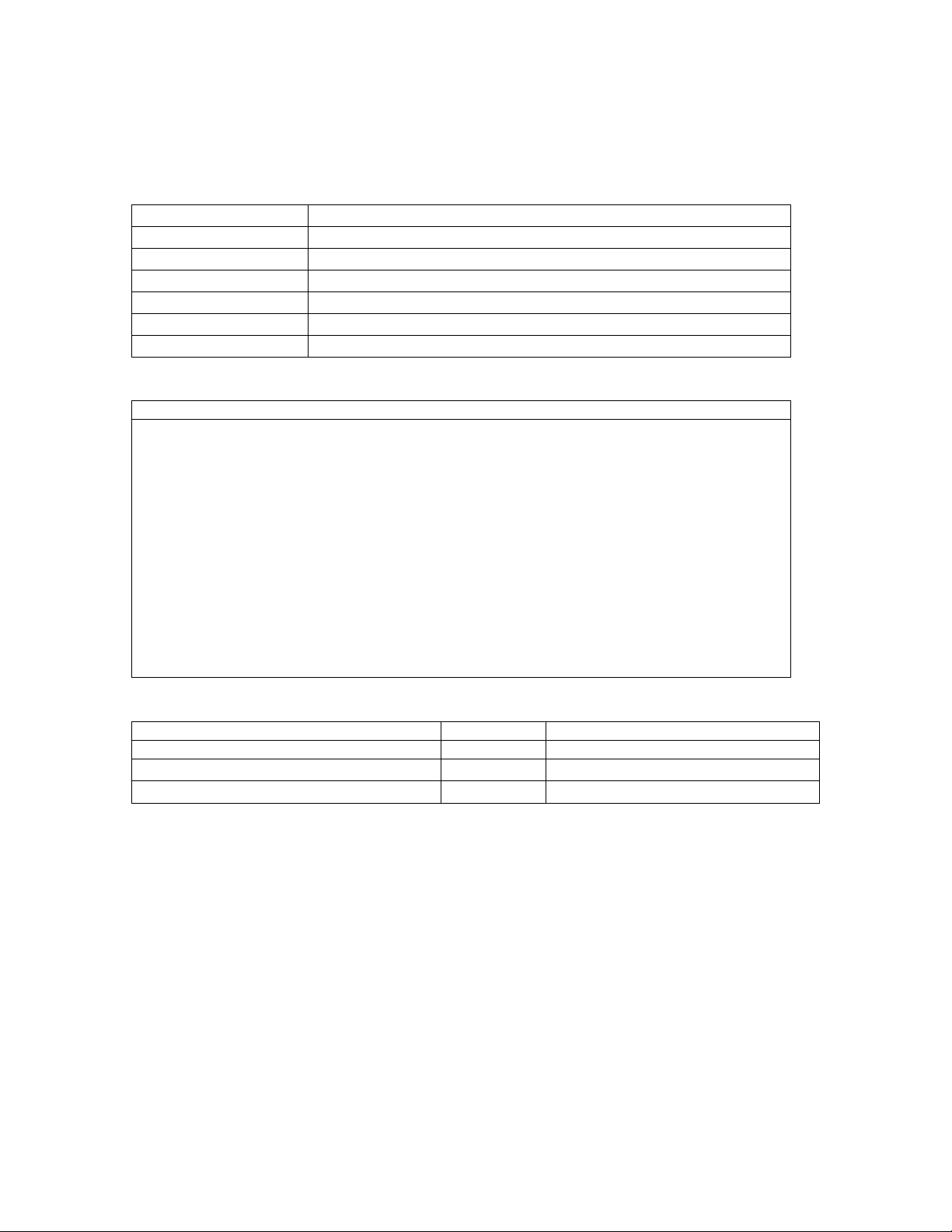
1.1.3 Labels ...................................................................................................................................................................................... 23
1.2 Emergency Stop Button .......................................................................................................................................................... 27
1.3 Laser Exposure ............................................................................................................................................................................ 28
1.4 Shutter Indicator ......................................................................................................................................................................... 29
1.5 Cautions, Warnings, and Notes ........................................................................................................................................... 30
1.5.1 Caution Statements ......................................................................................................................................................... 30
1.5.2 Warning Statements ........................................................................................................................................................ 30
1.5.3 Note Statements ................................................................................................................................................................ 30
1.6 Safety Concerns .......................................................................................................................................................................... 31
1.6.1 Pinch points .......................................................................................................................................................................... 31
1.6.2 Laser safety .......................................................................................................................................................................... 32
1.6.3 Radiation safety ................................................................................................................................................................. 32
1.6.4 Scatter Radiation ............................................................................................................................................................... 32
1.7 Controlling Computer and Accessories ........................................................................................................................... 34
1.7.1 Electrical Safety .................................................................................................................................................................. 34
1.7.2 Electromagnetic interference ..................................................................................................................................... 34
1.7.3 Peripheral Configurations ............................................................................................................................................. 34
1.7.4 Standard room configuration (system no. DF+12000 and greater) ......................................................... 34
1.7.5 Small room configuration (system no. DF+12000 and higher).................................................................... 35
1.7.6 Scanner power output configuration (system no. DF+11999 and lower) .............................................. 35
1.7.7 Wall outlet configuration (system no. DF+11999 and lower) ....................................................................... 35
Chapter 2 System Overview ............................................................................................................................................................. 37
2.0 PRODIGY System ......................................................................................................................................................................... 41
2.0.1 PRODIGY Electronics ........................................................................................................................................................ 43
2.1 Electronics ...................................................................................................................................................................................... 45
2.1.1 Cautions ................................................................................................................................................................................. 45
State: RELEASE - Document is released and under formal Change Control. Changes are subject to the ECR/ECO Process.
See the GEHC Myworkshop System to determine the status of this document.
Approved Document - LU7396DDW_r4.pdf Page 12 of 164

It is the responsibility of the user to verify this document originated from the controlled master and is the active revision prior to use. This
document contains confidential or proprietary information of GE Lunar. Neither the document nor the information therein is to be reproduced,
distributed, used or disclosed, either in whole or in part, except as specifically authorized by GE Lunar.
Page 12 of 163 PRODIGY 1-4 Service Manual (Rev. 3- 2012)
2.1.2 Electronics Pan ................................................................................................................................................................... 46
2.1.3 Scan Arm ............................................................................................................................................................................... 46
2.1.4 Power specifications ........................................................................................................................................................ 46
2.2 PRODIGY Block Diagrams ....................................................................................................................................................... 48
2.2.1 PRODIGY I (System numbers DF+11999 and lower) Power Distribution Block Diagram (AC
entrance) ........................................................................................................................................................................................... 48
2.2.2 PRODIGY System Block Diagram PRODIGY I System Block Diagram ....................................................... 49
2.2.3 PRODIGY I Peripheral Configuration Block Diagrams ...................................................................................... 50
2.2.4 PRODIGY II System / Power Block Diagram .......................................................................................................... 51
2.3 PRODIGY Fusing ........................................................................................................................................................................... 52
2.4 PRODIGY I (system numbers DF+11999 and lower) Single Board Controller ................................................. 53
2.4.1 SBC Functions ...................................................................................................................................................................... 53
2.4.2 SBC Reset ............................................................................................................................................................................... 53
2.4.3 SBC / Host PC Interface .................................................................................................................................................. 54
2.5 PRODIGY II Combined Single Board Controller (cSBC) (systems DF+12000 and greater) ........................ 54
2.5.1 cSBC System Architecture ............................................................................................................................................. 55
2.5.2 cSBC Functions ................................................................................................................................................................... 56
2.5.3 TRANS / LONG MOTOR Control and Status ........................................................................................................... 59
2.5.4 AGS ROLL ............................................................................................................................................................................... 59
2.5.5 AGS DAC ................................................................................................................................................................................. 59
2.5.6 SCANNER RESET ................................................................................................................................................................. 60
2.5.7 GE-LUNAR Model 7861 X-ray Generator Errors .................................................................................................. 61
2.5.8 DC FAIL .................................................................................................................................................................................... 61
2.5.9 DCA / AGS / BIAS DAC's ................................................................................................................................................... 62
2.5.10 KV/mA DAC ........................................................................................................................................................................ 62
2.5.11 ARC/FIL DAC ....................................................................................................................................................................... 62
2.5.12 PEAK DAC ............................................................................................................................................................................ 62
2.5.13 MAX PLD Peripherals ..................................................................................................................................................... 62
2.5.14 Interrupts ............................................................................................................................................................................ 63
2.5.15 MASTER RESET .................................................................................................................................................................. 63
2.5.16 SUICIDE RESET .................................................................................................................................................................. 64
2.5.17 MISC OUT............................................................................................................................................................................. 64
2.5.18 MISC IN ................................................................................................................................................................................. 65
State: RELEASE - Document is released and under formal Change Control. Changes are subject to the ECR/ECO Process.
See the GEHC Myworkshop System to determine the status of this document.
Approved Document - LU7396DDW_r4.pdf Page 13 of 164

It is the responsibility of the user to verify this document originated from the controlled master and is the active revision prior to use. This
document contains confidential or proprietary information of GE Lunar. Neither the document nor the information therein is to be reproduced,
distributed, used or disclosed, either in whole or in part, except as specifically authorized by GE Lunar.
PRODIGY 1-4 Service Manual (Rev. 3- 2012) Page 13 of 163
2.5.19 Stepper Motor Control .................................................................................................................................................. 65
2.5.20 OMI/OMD Input ................................................................................................................................................................ 65
2.5.21 Patient Positioners ......................................................................................................................................................... 67
2.5.22 Limit Switches .................................................................................................................................................................. 67
2.5.23 X-ray Source Control / Mechanical Interlocks .................................................................................................. 67
2.5.24 Shutter / Collimator Drive ........................................................................................................................................... 67
2.5.25 End of Exposure Alarm ................................................................................................................................................. 68
2.5.26 Panel LED's ......................................................................................................................................................................... 68
2.5.27 HVPS Control ..................................................................................................................................................................... 68
2.5.28 ADC ........................................................................................................................................................................................ 68
2.5.29 mA Low Range ................................................................................................................................................................. 69
2.5.30 Detector Interface .......................................................................................................................................................... 69
2.5.31 Communications Ports ................................................................................................................................................ 69
2.5.32 Debug RS-232 Port ........................................................................................................................................................ 69
2.5.33 Diagnostic LED's .............................................................................................................................................................. 70
2.6 Power Distribution (PRODIGY II Systems DF+1200 and greater) ......................................................................... 71
2.7 Tube Head and X-ray Insert .................................................................................................................................................. 71
2.7.1 X-ray generation and Spectrum ................................................................................................................................ 71
2.8 X-ray Generator (High Voltage Power Supply(ies)) ..................................................................................................... 72
2.9 MAX Board (PRODIGY I systems DF+11999 and lower only) .................................................................................. 72
2.9.1 MAX Board Function ........................................................................................................................................................ 72
2.9.2 Dedicated +28VDC power supply .............................................................................................................................. 72
2.10 XORB Board (PRODIGY I Systems DF+11999 and lower only) ............................................................................ 73
2.11 Detector Sub System .............................................................................................................................................................. 74
2.11.1 Detector Overview ......................................................................................................................................................... 74
2.11.2 Detector Operation ........................................................................................................................................................ 74
2.11.3 Detector Daughter Board Overview ...................................................................................................................... 75
2.11.4 Detector Daughter Board Operation .................................................................................................................... 76
2.11.5 Detector Mother Board Overview ........................................................................................................................... 76
2.11.6 Detector Mother Board Operation ......................................................................................................................... 76
2.12 FOINK (PRODIGY I Systems DF+11999 and lower only) ......................................................................................... 78
2.12.1 FOINK Functions .............................................................................................................................................................. 78
2.12.2 Motion Control and Detection .................................................................................................................................. 78
State: RELEASE - Document is released and under formal Change Control. Changes are subject to the ECR/ECO Process.
See the GEHC Myworkshop System to determine the status of this document.
Approved Document - LU7396DDW_r4.pdf Page 14 of 164

It is the responsibility of the user to verify this document originated from the controlled master and is the active revision prior to use. This
document contains confidential or proprietary information of GE Lunar. Neither the document nor the information therein is to be reproduced,
distributed, used or disclosed, either in whole or in part, except as specifically authorized by GE Lunar.
Page 14 of 163 PRODIGY 1-4 Service Manual (Rev. 3- 2012)
2.13 Display Panel .............................................................................................................................................................................. 79
2.14 Audible X-RAY OFF Signal ..................................................................................................................................................... 80
2.15 X-Ray Collimator Subsystem .............................................................................................................................................. 80
2.16 PRODIGY Specifications ......................................................................................................................................................... 80
2.17 Secondary Calibration / Daily QA ..................................................................................................................................... 80
2.17.1 Secondary Calibration overview .............................................................................................................................. 80
2.17.2 Starting the Daily QA (secondary calibration) ................................................................................................... 81
2.17.3 Tests Performed in the Secondary Calibration ................................................................................................. 82
2.17.4 QA Database ..................................................................................................................................................................... 85
Chapter 3 Service Software .............................................................................................................................................................. 87
3.0 Diagnostic Software .................................................................................................................................................................. 89
3.0.1 To Access the Service Software: ................................................................................................................................. 89
3.1 The Tools Menu ............................................................................................................................................................................ 91
3.1.1 Spectrum ............................................................................................................................................................................... 91
3.1.2 Stability Run .......................................................................................................................................................................... 91
3.1.3 Signal Monitor ..................................................................................................................................................................... 91
3.1.4 Primary Calibration ........................................................................................................................................................... 91
3.1.5 Secondary Verification .................................................................................................................................................... 91
3.1.6 Pileup ....................................................................................................................................................................................... 91
3.1.7 Set Download Parameters ............................................................................................................................................ 91
3.1.8 enCORE Composer ............................................................................................................................................................ 91
3.1.9 Error Log ................................................................................................................................................................................. 91
3.1.10 Copy Configuration ........................................................................................................................................................ 92
3.1.11 User Options ...................................................................................................................................................................... 92
3.1.12 Service Options ................................................................................................................................................................ 92
3.1.13 Outbox .................................................................................................................................................................................. 92
3.1.14 System File Editor ............................................................................................................................................................ 92
3.2 Tools / Diagnostics Menu ........................................................................................................................................................ 93
3.2.1 Pileup ....................................................................................................................................................................................... 93
3.2.2 Calibration Pileup ............................................................................................................................................................... 93
3.2.3 Spillover .................................................................................................................................................................................. 93
3.2.4 Count Rate ............................................................................................................................................................................ 93
State: RELEASE - Document is released and under formal Change Control. Changes are subject to the ECR/ECO Process.
See the GEHC Myworkshop System to determine the status of this document.
Approved Document - LU7396DDW_r4.pdf Page 15 of 164

It is the responsibility of the user to verify this document originated from the controlled master and is the active revision prior to use. This
document contains confidential or proprietary information of GE Lunar. Neither the document nor the information therein is to be reproduced,
distributed, used or disclosed, either in whole or in part, except as specifically authorized by GE Lunar.
PRODIGY 1-4 Service Manual (Rev. 3- 2012) Page 15 of 163
3.2.5 Scanner Motion .................................................................................................................................................................. 93
3.2.6 Scanner Detector .............................................................................................................................................................. 94
3.2.7 Scanner X-ray ..................................................................................................................................................................... 94
3.2.8 Lin/Rep .................................................................................................................................................................................... 95
3.2.9 Limit Switch Adjustment ................................................................................................................................................ 95
3.2.10 Scanner Disconnect ...................................................................................................................................................... 95
3.3 Diagnostic Scan Modes - ........................................................................................................................................................ 96
3.3.1 Table Top Scan - ................................................................................................................................................................ 96
3.3.2 Alignment Scan .................................................................................................................................................................. 96
3.3.3 Beam Wobble scan .......................................................................................................................................................... 96
3.3.4 Hacksaw ................................................................................................................................................................................ 96
3.4 Error Log ......................................................................................................................................................................................... 97
3.4.1 Printing the Error Log. ..................................................................................................................................................... 98
3.4.2 Troubleshooting Help software ................................................................................................................................ 100
3.4.3 Reading the Error Log ................................................................................................................................................... 102
Chapter 4 Troubleshooting ............................................................................................................................................................ 103
4.0 Diagnostic Failure Codes ...................................................................................................................................................... 105
4.1 Transverse Motion failure ..................................................................................................................................................... 105
4.1.1 Operator Induced - switch closed during scan ................................................................................................ 105
4.1.2 Mechanical Failures - Unusual noise or irregular motion ........................................................................... 106
4.1.3 Loss of OMI/OMD signal ............................................................................................................................................... 107
4.2 Longitudinal Motion failure .................................................................................................................................................. 109
4.2.1 Limit Switch Tripped During a Scan ....................................................................................................................... 109
4.2.2 Longitudinal Binding ...................................................................................................................................................... 109
4.2.3 Loss of OMI/OMD Signal ............................................................................................................................................... 111
4.3 Failure of the 28V power supply........................................................................................................................................ 113
4.4 Emergency Stop Button ........................................................................................................................................................ 113
4.5 Tube Head Thermostat .......................................................................................................................................................... 114
4.6 Communication Error ............................................................................................................................................................. 114
4.7 Other Diagnostic Failure Codes ......................................................................................................................................... 114
4.7.1 Reasons For Invalid Diagnostic Failures .............................................................................................................. 114
4.8 Failing Quality Assurance Test ........................................................................................................................................... 114
4.8.1 Block Position .................................................................................................................................................................... 115
State: RELEASE - Document is released and under formal Change Control. Changes are subject to the ECR/ECO Process.
See the GEHC Myworkshop System to determine the status of this document.
Approved Document - LU7396DDW_r4.pdf Page 16 of 164

It is the responsibility of the user to verify this document originated from the controlled master and is the active revision prior to use. This
document contains confidential or proprietary information of GE Lunar. Neither the document nor the information therein is to be reproduced,
distributed, used or disclosed, either in whole or in part, except as specifically authorized by GE Lunar.
Page 16 of 163 PRODIGY 1-4 Service Manual (Rev. 3- 2012)
4.8.2 Beam Stop Action ........................................................................................................................................................... 115
4.8.3 Mean% Spillover .............................................................................................................................................................. 115
4.8.4 Reference Counts and Ratio...................................................................................................................................... 115
4.8.5 Ratio Fluctuations ........................................................................................................................................................... 115
4.8.6 Transverse or Longitudinal Mechanics ................................................................................................................ 116
4.8.7 Tissue Value ....................................................................................................................................................................... 116
4.8.8 Bone Mineral of the Standard Chambers ........................................................................................................... 117
4.8.9 Symptoms of High and Low KV ............................................................................................................................... 117
4.9 Reference Counts..................................................................................................................................................................... 118
4.9.1 Unstable Counts .............................................................................................................................................................. 118
4.9.2 No Counts ........................................................................................................................................................................... 118
4.9.3 Decreasing Reference Counts .................................................................................................................................. 120
4.10 Arcing .......................................................................................................................................................................................... 120
4.10.1 Limit Switch Tripped During Scan ........................................................................................................................ 121
4.11 Imaging Problems ................................................................................................................................................................. 122
4.11.1 White, or Grey in the first or second scan line: .............................................................................................. 122
4.11.2 Femur Scan Problems ................................................................................................................................................ 122
4.11.3 AP-Spine Image Problems: Probable causes .................................................................................................. 123
4.11.4 Broken Signal Cable .................................................................................................................................................... 123
4.11.5 Loss of tube head current ........................................................................................................................................ 123
4.11.6 X-Ray Relay Failure ..................................................................................................................................................... 123
4.11.7 Unstable AC Line .......................................................................................................................................................... 123
4.11.8 Arcing ................................................................................................................................................................................. 124
4.12 Failing Alignment Test Results ........................................................................................................................................ 125
4.12.1 Image ................................................................................................................................................................................. 125
4.13 Indicator Failures ................................................................................................................................................................... 126
4.13.1 X-ray On LED Blinking ................................................................................................................................................ 126
4.13.2 Shutter Open LED Blinking ....................................................................................................................................... 126
4.13.3 Shutter Not Operating ............................................................................................................................................... 127
4.13.4 End of Exposure Alarm During Scan ................................................................................................................... 127
4.14 Communications Failures ................................................................................................................................................. 128
4.15 Viewing Quality Assurance Trends ............................................................................................................................... 128
State: RELEASE - Document is released and under formal Change Control. Changes are subject to the ECR/ECO Process.
See the GEHC Myworkshop System to determine the status of this document.
Approved Document - LU7396DDW_r4.pdf Page 17 of 164

It is the responsibility of the user to verify this document originated from the controlled master and is the active revision prior to use. This
document contains confidential or proprietary information of GE Lunar. Neither the document nor the information therein is to be reproduced,
distributed, used or disclosed, either in whole or in part, except as specifically authorized by GE Lunar.
PRODIGY 1-4 Service Manual (Rev. 3- 2012) Page 17 of 163
4.15.1 What to Look for in the QA History ...................................................................................................................... 128
4.16 MAX Board Troubleshooting ............................................................................................................................................. 130
4.17 FOINK Board Troubleshooting ......................................................................................................................................... 131
4.18 OMI/OMD Board Troubleshooting ................................................................................................................................. 132
4.19 SBC Troubleshooting ............................................................................................................................................................ 133
4.20 XORB Troubleshooting......................................................................................................................................................... 135
4.21 Detector Motherboard Troubleshooting .................................................................................................................... 136
4.22 Detector Daughter Board Troubleshooting .............................................................................................................. 138
Chapter 5 Service Procedures....................................................................................................................................................... 139
5.0 Reloading LUNAR Software ................................................................................................................................................. 141
5.1 Peaking the Detector .............................................................................................................................................................. 141
5.1.1 Peaking Procedure ......................................................................................................................................................... 141
5.2 Tube Head Replacement ...................................................................................................................................................... 142
5.2.1 Shelf Life............................................................................................................................................................................... 143
5.2.2 Mounting The Tube Head ............................................................................................................................................ 143
5.3 Lower Cable Bundle Replacement ................................................................................................................................... 144
5.3.1 Procedure ............................................................................................................................................................................ 144
5.4 Upper Cable Bundle Replacement ................................................................................................................................... 146
5.4.1 Procedure ............................................................................................................................................................................ 146
5.5 Tube Head Control Cable Replacement ........................................................................................................................ 149
5.5.1 Procedure ............................................................................................................................................................................ 149
5.6 Tests to Perform after Service ............................................................................................................................................ 152
5.6.1 Test Work Instructions and/or References to Work Instructions ....................................................... 152
Chapter 6 Maintenance .................................................................................................................................................................... 157
6.0 Preventative Maintenance ................................................................................................................................................... 159
6.0.1 QA History ........................................................................................................................................................................... 159
6.0.2 Repacking the High Voltage Cable Connectors ............................................................................................... 159
6.0.3 Wear ...................................................................................................................................................................................... 159
6.0.4 Cleaning ............................................................................................................................................................................... 159
6.0.5 Inspection............................................................................................................................................................................ 160
6.0.6Tests ........................................................................................................................................................................................ 160
6.1 Unusual Sounds ........................................................................................................................................................................ 160
6.2 Change Orders ........................................................................................................................................................................... 160
State: RELEASE - Document is released and under formal Change Control. Changes are subject to the ECR/ECO Process.
See the GEHC Myworkshop System to determine the status of this document.
Approved Document - LU7396DDW_r4.pdf Page 18 of 164

It is the responsibility of the user to verify this document originated from the controlled master and is the active revision prior to use. This
document contains confidential or proprietary information of GE Lunar. Neither the document nor the information therein is to be reproduced,
distributed, used or disclosed, either in whole or in part, except as specifically authorized by GE Lunar.
Page 18 of 163 PRODIGY 1-4 Service Manual (Rev. 3- 2012)
This page left blank intentionally.
State: RELEASE - Document is released and under formal Change Control. Changes are subject to the ECR/ECO Process.
See the GEHC Myworkshop System to determine the status of this document.
Approved Document - LU7396DDW_r4.pdf Page 19 of 164

It is the responsibility of the user to verify this document originated from the controlled master and is the active revision prior to use. This
document contains confidential or proprietary information of GE Lunar. Neither the document nor the information therein is to be reproduced,
distributed, used or disclosed, either in whole or in part, except as specifically authorized by GE Lunar.
PRODIGY 1-4 Service Manual (Rev. 3- 2012) Page 19 of 163
1
Chapter 1 Safety
This chapter highlights safety devices and features a Service Engineer should know
before servicing a PRODIGY system.
Chapter Contents:
1.0 General Safety
1.1 Symbols and labels found on the PRODIGY
1.1.1 External Symbols
1.1.2 Internal Symbols
1.1.3 Labels
1.2 Emergency Stop Button
1.3 Laser Exposure
1.4 Shutter Indicator
1.5 Cautions, Warnings, and Notes
1.5.1 Caution Statements
1.5.2 Warning Statements
1.5.3 Note Statements
1.6 Safety Concerns
1.6.1 Pinch points
1.6.2 Laser safety
1.6.3 Radiation safety
1.6.4 Scatter Radiation
1.7 Controlling Computer and Accessories
1.7.1 Electrical Safety
1.7.3 Peripheral Configurations
1.7.4 Standard room configuration (system no. DF+12000 and greater)
1.7.5 Small room configuration (system no. DF+12000 and higher)
1.7.6 Scanner power output configuration (system no. DF+11999 and lower)
1.7.7 Wall outlet configuration (system no. DF+11999 and lower)
Figure 1-1. The PRODIGY Display Panel
State: RELEASE - Document is released and under formal Change Control. Changes are subject to the ECR/ECO Process.
See the GEHC Myworkshop System to determine the status of this document.
Approved Document - LU7396DDW_r4.pdf Page 20 of 164

It is the responsibility of the user to verify this document originated from the controlled master and is the active revision prior to use. This
document contains confidential or proprietary information of GE Lunar. Neither the document nor the information therein is to be reproduced,
distributed, used or disclosed, either in whole or in part, except as specifically authorized by GE Lunar.
Page 20 of 163 PRODIGY 1-4 Service Manual (Rev. 3- 2012)
Figure 1-2. Laser Warning Label (U.S. systems only)
Figure 1-4. Laser Warning Label (International systems only)
Figure 1-5. Source (x-rays) off - Shutter closed (green)
Figure 1-6. Source (x-rays) on - Shutter open (yellow)
Figure 1-7. Potential Pinch Points on the PRODIGY
Figure 1-8. PRODIGY Iso-Dose Diagram
State: RELEASE - Document is released and under formal Change Control. Changes are subject to the ECR/ECO Process.
See the GEHC Myworkshop System to determine the status of this document.
Approved Document - LU7396DDW_r4.pdf Page 21 of 164

It is the responsibility of the user to verify this document originated from the controlled master and is the active revision prior to use. This
document contains confidential or proprietary information of GE Lunar. Neither the document nor the information therein is to be reproduced,
distributed, used or disclosed, either in whole or in part, except as specifically authorized by GE Lunar.
PRODIGY 1-4 Service Manual (Rev. 3- 2012) Page 21 of 163
1.0 General Safety
• DO NOT attempt to service the PRODIGY without first reading this manual.
• DO NOT attempt any repairs without prior instructions from authorized LUNAR personnel.
• In order to maintain electrical safety and electromagnetic compatibility, the Lunar PRODIGY is
only to be connected to a computer, printer, and peripherals that are certified to be compliant
with IEC 950/EN 60950 Safety of information technology equipment, including electrical business
equipment and IEC 601-1-2 Medical electrical equipment, Part 1: General requirements for safety,
2. Collateral Standard: Electromagnetic compatibility - Requirements and tests. Emergency Stop
Button.
• Ionizing Radiation Exposure: When power is applied, this equipment may generate ionizing
radiation. Take precautions that no part of the body passes through the x-ray beam when the
equipment is energized. Avoid scatter radiation during warm-up and testing by maintaining a
safe distance from the x-ray beam. See the Safety and Specification manual for equipment
appropriate distance and other precautions regarding ionizing radiation. All operators must be
properly trained regarding ionizing radiation and take adequate steps to protect against injury.
• Electric Shock: This equipment contains high voltages. When the tabletop/panels/ shrouds are
removed, visually confirm that power cord is unplugged and remains unplugged until power is
required to complete the procedure. When servicing while energized, take precautions to prevent
electric shock.
• Moving Parts and Pinch Points: Avoid moving parts and pinch points (e.g. belt/pulley, arm/back
rail, green wheels/rail).
• Sharp Edges: Take precautions to prevent injury from contact with component edges (e.g.
OMI/OMD wheel, arm slot cover).
• Hot Surfaces: Keep hands clear or allow components to cool before servicing. (e.g. stepper
motors, hard drives, power supplies and microprocessors).
• Heavy Lifting: Obtain help lifting or moving any object weighing over EHS limits. Ask for
assistance when maneuvering awkward objects (e.g. tabletop).
• Laser Radiation: Do not stare into the laser beam at any time. The reflection from the tabletop
or shutter/collimator assembly is sufficient to determine if the laser is on.
• Follow appropriate Lockout/Tagout procedures as described in MyLearning training course
GEMS-EHS-LOTOAth.
• Wear appropriate PPE (Personal Protective Equipment) while servicing the equipment, e.g. eye
protection and steel-toe/composite-toe shoes.
State: RELEASE - Document is released and under formal Change Control. Changes are subject to the ECR/ECO Process.
See the GEHC Myworkshop System to determine the status of this document.
Approved Document - LU7396DDW_r4.pdf Page 22 of 164

It is the responsibility of the user to verify this document originated from the controlled master and is the active revision prior to use. This
document contains confidential or proprietary information of GE Lunar. Neither the document nor the information therein is to be reproduced,
distributed, used or disclosed, either in whole or in part, except as specifically authorized by GE Lunar.
Page 22 of 163 PRODIGY 1-4 Service Manual (Rev. 3- 2012)
1.1 Symbols and labels found on the PRODIGY
1.1.1 External Symbols
The following symbols are found on the PRODIGY, in the Operators manual, and in the Service Manual.
Attention: contains important safety information such as the location of a
pinch point.
Emergency Stop Button: shows the location of the emergency stop button.
Power On: shows the location of the Power On indicator and the switch
position for Power On.
Power Off: shows the switch position for Power Off.
Laser On: shows the location of the Laser On indicator. It is found only on
systems delivered internationally.
Shutter Open: shows the location of the Shutter Open indicator.
X-ray On: shows the location of the X-Ray On indicator.
Type B Equipment: shows that the scanner has Type B protection against
electrical shock.
State: RELEASE - Document is released and under formal Change Control. Changes are subject to the ECR/ECO Process.
See the GEHC Myworkshop System to determine the status of this document.
Approved Document - LU7396DDW_r4.pdf Page 23 of 164

It is the responsibility of the user to verify this document originated from the controlled master and is the active revision prior to use. This
document contains confidential or proprietary information of GE Lunar. Neither the document nor the information therein is to be reproduced,
distributed, used or disclosed, either in whole or in part, except as specifically authorized by GE Lunar.
PRODIGY 1-4 Service Manual (Rev. 3- 2012) Page 23 of 163
1.1.2 Internal Symbols
The following symbols are found inside the PRODIGY, and in the Service Manual.
Protective Earth: shows the location of a Protective Earth Terminal.
Functional Earth: shows the location of a Functional Earth Terminal.
1.1.3 Labels
The following labels are found on the PRODIGY Scanner.
Laser Caution Label: Shows that the scanner uses a
Class II laser. This label is not found on systems
shipped to Canada.
Laser Caution Label: Canada only
State: RELEASE - Document is released and under formal Change Control. Changes are subject to the ECR/ECO Process.
See the GEHC Myworkshop System to determine the status of this document.
Approved Document - LU7396DDW_r4.pdf Page 24 of 164

It is the responsibility of the user to verify this document originated from the controlled master and is the active revision prior to use. This
document contains confidential or proprietary information of GE Lunar. Neither the document nor the information therein is to be reproduced,
distributed, used or disclosed, either in whole or in part, except as specifically authorized by GE Lunar.
Page 24 of 163 PRODIGY 1-4 Service Manual (Rev. 3- 2012)
Tube Head Assembly Label (system number
DF+12000 and greater): This label gives tube head
assembly and x-ray source characteristics
information. It is located on the tube head assembly
and the foot panel of the scanner.
Tube Head Assembly Label (system number
DF+11999 a lower): This label gives tube head
assembly and x-ray source characteristics
information. It located on the tube head assembly
and the foot panel of the scanner.
A definition of each symbol on this label follows:
Tube Insert
X-ray Source
Focal Point
Inherent Filtration
State: RELEASE - Document is released and under formal Change Control. Changes are subject to the ECR/ECO Process.
See the GEHC Myworkshop System to determine the status of this document.
Approved Document - LU7396DDW_r4.pdf Page 25 of 164
It is the responsibility of the user to verify this document originated from the controlled master and is the active revision prior to use. This
document contains confidential or proprietary information of GE Lunar. Neither the document nor the information therein is to be reproduced,
distributed, used or disclosed, either in whole or in part, except as specifically authorized by GE Lunar.
PRODIGY 1-4 Service Manual (Rev. 3- 2012) Page 25 of 163
High Voltage Power Supply: This label gives high
voltage power supply (x-ray generator) information.
It is located on the positive and negative power
supply(s), and foot panel of the scanner.
X-ray Controller: This label shows x-ray controller
compliance. It is located on the foot panel of the
scanner.
Collimator Assembly: This label gives collimator
assembly information. It is located on the collimator
and foot panel of the scanner.
Warning Label and Radiation Symbol: The Warning
label shows that the system uses ionizing radiation. It
is found only on systems delivered in the United
States. Always obey instructions for safe operation.
Radiation Label: This label shows that the system
uses ionizing radiation.
State: RELEASE - Document is released and under formal Change Control. Changes are subject to the ECR/ECO Process.
See the GEHC Myworkshop System to determine the status of this document.
Approved Document - LU7396DDW_r4.pdf Page 26 of 164

It is the responsibility of the user to verify this document originated from the controlled master and is the active revision prior to use. This
document contains confidential or proprietary information of GE Lunar. Neither the document nor the information therein is to be reproduced,
distributed, used or disclosed, either in whole or in part, except as specifically authorized by GE Lunar.
Page 26 of 163 PRODIGY 1-4 Service Manual (Rev. 3- 2012)
Grounding Reliability Label: This label states that
grounding reliability can only be maintained when
using a “Hospital Grade” or “Hospital Only” receptacle.
It is only found on systems delivered in the United
States.
State: RELEASE - Document is released and under formal Change Control. Changes are subject to the ECR/ECO Process.
See the GEHC Myworkshop System to determine the status of this document.
Approved Document - LU7396DDW_r4.pdf Page 27 of 164

It is the responsibility of the user to verify this document originated from the controlled master and is the active revision prior to use. This
document contains confidential or proprietary information of GE Lunar. Neither the document nor the information therein is to be reproduced,
distributed, used or disclosed, either in whole or in part, except as specifically authorized by GE Lunar.
PRODIGY 1-4 Service Manual (Rev. 3- 2012) Page 27 of 163
1.2 Emergency Stop Button
The Emergency Stop Button is a round red button located on the scanner display panel (see Figure 1-1).
When pressed, power is removed from the X-ray tube head, the laser, and the shutter is closed. Power is
also removed from the scan arm motors, allowing the operator/patient to push the scan arm out of the
way.
Figure 1-1. The PRODIGY Display Panel
State: RELEASE - Document is released and under formal Change Control. Changes are subject to the ECR/ECO Process.
See the GEHC Myworkshop System to determine the status of this document.
Approved Document - LU7396DDW_r4.pdf Page 28 of 164

It is the responsibility of the user to verify this document originated from the controlled master and is the active revision prior to use. This
document contains confidential or proprietary information of GE Lunar. Neither the document nor the information therein is to be reproduced,
distributed, used or disclosed, either in whole or in part, except as specifically authorized by GE Lunar.
Page 28 of 163 PRODIGY 1-4 Service Manual (Rev. 3- 2012)
1.3 Laser Exposure
The PRODIGY is equipped with a Class II Laser device. This laser is used for patient positioning. A Class II
rating indicates a low power visible laser that is not normally hazardous to eyesight but has the potential
to be hazardous if viewed directly for an extended period of time. Because of this potential hazard, DO
NOT stare directly into the beam while the laser is in operation, and DO NOT allow the beam to shine
directly into the patients' eyes. No specific eye protection is required with a Class II laser.
A amber laser-on indicator, located on the front of the scan arm, is lit when the laser is on. The program
activates the laser during positioning for an image acquisition. The program then turns off the laser
when you begin the scan. The emergency stop button will turn off the laser.
There is a caution label (Figure 1-2) on the scan arm near the Display Panel.
Figure 1-2. Laser Warning Label (U.S. systems only)
Figure 1-3. Laser Warning Label (Canadian Systems only)
Figure 1-4. Laser Warning Label (International systems only)
Note: DO NOT STARE INTO THE BEAM while the laser is operating.
State: RELEASE - Document is released and under formal Change Control. Changes are subject to the ECR/ECO Process.
See the GEHC Myworkshop System to determine the status of this document.
Approved Document - LU7396DDW_r4.pdf Page 29 of 164
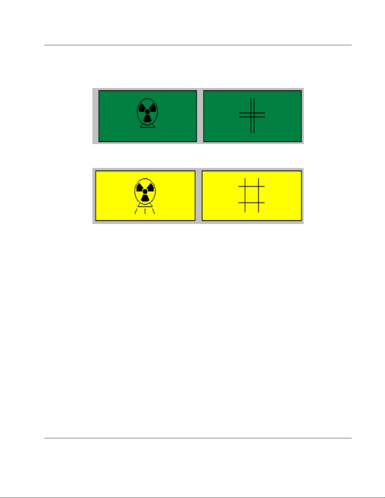
It is the responsibility of the user to verify this document originated from the controlled master and is the active revision prior to use. This
document contains confidential or proprietary information of GE Lunar. Neither the document nor the information therein is to be reproduced,
distributed, used or disclosed, either in whole or in part, except as specifically authorized by GE Lunar.
PRODIGY 1-4 Service Manual (Rev. 3- 2012) Page 29 of 163
1.4 Shutter Indicator
This symbol is used to indicate an open-shutter condition in accordance with the safety standards
established by the International Electrotechnical Commission (IEC).
Figure 1-5. S ou r c e ( x-rays) off - Shutter closed (green)
Figur e 1 -6 . So u r c e (x -rays) on - Shutter open (yellow)
This symbol appears near the yellow X-ray shutter-open indicator light. The X-ray shutter-open indicator
light is located on the Display Panel on the scan arm near the front.
Note: When the x-ray on / shutter open symbol appears in literature associated with the PRODIGY scanner,
it will be used to indicate that the procedure being described results in an open shutter condition. During
these times personnel should exercise caution to avoid excessive exposure t o th e X -rays.
State: RELEASE - Document is released and under formal Change Control. Changes are subject to the ECR/ECO Process.
See the GEHC Myworkshop System to determine the status of this document.
Approved Document - LU7396DDW_r4.pdf Page 30 of 164
 Loading...