


|
GE Medical Systems IT GmbH |
Beethoven Str. 239 |
|
3030 Ohmeda Dr. |
D-42655 Solingen |
||
Munzinger Strasse 3-5 |
|||
Madison, WI 53718 |
Germany |
||
D-79111 Freiburg, Germany |
|||
USA |
+49-212-2802-0 |
||
+49 212 2802 652 |
|||
+1 (800) 437-1171 |
+49-212-2802-390 (fax) |
||
+49 0761 45 43 233 (fax) |
|||
|
Asia/Pacific |
||
China |
France |
||
No. 19 Changjiang Road |
11 Avenue Morane Saulnier |
4-7-127 Asahigaoka |
|
Wuxi, Jiangsu, 214028 |
78 457 VELIZY |
Hino-shi, Tokyo 191-8503 |
|
P.R.C. |
+33-1-34-49-5365 |
Japan |
|
+86-510-85225888 |
+33-1-34-49-5406 (fax) |
+81-42-585-5111 |
|
+86-510-85226688 (fax) |
|
+81-42-585-3077 (fax) |
DPX Series |
YZB/USA 2099 |
DPX-Bravo SFDA Register Number: |
JSFDA(I) 2009 No.2300674 |
|
SFDA(I) 20023301115 |
Product Standard Number: |
YZB/ 0637-2009 |
Prodigy Series |
YZB/USA 0509 |
Production License Number: |
2001-0041 |
|
SFDA(I) 20043301375 |
Production & Registration Address: |
No.19 Changjiang Road, Wuxi National Hi-Tech |
iDXA |
YZB/USA 1104-2007 |
|
Development Zone, Jiangsu P.R.China |
|
SFDA(I) 20073302084 |
Service Address: |
GE Medical Systems Trade Development |
|
|
|
Corporation (Shanghai) Co.,Ltd |
|
|
|
3 floor, CTP1 building, |
|
|
|
No1. Huatuo Road |
|
|
|
ZhangjiangGaoke, Shanghai |
|
|
Postal Code: |
201203 |
|
|
Contact Phone: |
8008108188 |
Operator's Manual for DPX-NT, DPX-MD+, DPX Bravo, DPX Duo, Prodigy, Prodigy Advance, Prodigy Primo, and Lunar iDXA x-ray bone densitometers systems using enCORE with Windows XP Professional computers. GE Healthcare recommends viewing the instructions for navigating the Lunar enCORE™ based X-ray Bone Densitometer User Manual before proceeding through the online guide for the first time. Before operating scanner, read the Safety and Technical Specifications manual which is part of operator's instructions.
Table of Contents
Introduction................................................................................................................. |
7 |
||
Intended Use....................................................................................................... |
7 |
||
Device Descriptions ............................................................................................ |
7 |
||
Installation and Operation ................................................................................. |
11 |
||
1.0 Screens and Toolbars ....................................................................................... |
14 |
||
1.1 |
Overview ..................................................................................................... |
14 |
|
1.2 |
|
Main Screen ............................................................................................... |
15 |
1.3 |
|
Analyze Screen.......................................................................................... |
16 |
1.4 |
|
Directory Screen ........................................................................................ |
18 |
1.5 |
|
New Measurement Screen ........................................................................ |
20 |
1.6 |
|
Quality Assurance screen .......................................................................... |
23 |
1.7 |
|
Options....................................................................................................... |
24 |
2.0 Quality Assurance .............................................................................................. |
34 |
||
3.0 Measurement .................................................................................................... |
37 |
||
3.1 |
Measurement Overview & Warnings .......................................................... |
37 |
|
3.2 |
|
Measurement Procedures.......................................................................... |
38 |
3.3 |
|
Pediatrics Option....................................................................................... |
53 |
3.4 |
|
OneScan .................................................................................................... |
53 |
3.5 |
|
OneVision Feature ..................................................................................... |
55 |
3.6 |
|
Orthopedic Hip Option ............................................................................... |
56 |
3.7 |
Quick View .................................................................................................. |
58 |
|
3.8 |
Spine Phantom Procedure.......................................................................... |
58 |
|
4.0 Analysis Procedures........................................................................................... |
60 |
||
4.1 |
|
Basic analysis procedures ......................................................................... |
61 |
4.2 |
|
AP Spine Analysis...................................................................................... |
64 |
4.3 |
|
APVA Morphometry Analysis..................................................................... |
66 |
4.4 |
|
APVA Spine Geometry Analysis ................................................................ |
66 |
4.5 |
Femur/ DualFemur Analysis ....................................................................... |
68 |
|
4.6 |
Advanced Hip Analysis ............................................................................... |
69 |
|
4.7 |
|
Total Body Analysis.................................................................................... |
73 |
4.8 |
|
Composition Analysis................................................................................. |
75 |
4.9 |
|
Lateral Spine Analysis ............................................................................... |
85 |
4.10 |
LVA Morphometry Analysis....................................................................... |
86 |
|
4.11 |
LVA Spine Geometry Analysis.................................................................. |
93 |
|
4.12 |
Forearm Analysis ..................................................................................... |
94 |
|
4.13 |
Hand Analysis .......................................................................................... |
96 |
|
4.14 |
Orthopedic Analysis .................................................................................. |
97 |
|
4.15 |
Pediatric Analysis...................................................................................... |
98 |
|
4.16 |
Small Animal Body Analysis ................................................................... |
101 |
|
4.17 |
Custom Reference Population ................................................................ |
103 |
|
4.18 |
ScanCheck™ ......................................................................................... |
104 |
|
4.19 |
Practice Management Tools .................................................................. |
106 |
|
4.20 |
Composer Reports................................................................................. |
110 |
|
4.21 |
DXA Results Report................................................................................ |
114 |
|
4.22 |
Precision Calculator ................................................................................ |
118 |
|
4.23 |
Custom Analysis .................................................................................... |
120 |
|
4.24 |
FRAX* 10-Year Fracture Risk................................................................. |
122 |
|
5.0 Database Maintenance .................................................................................... |
124 |
||
5.1 |
Maintenance Procedures .......................................................................... |
125 |
|
5.2 |
|
Compress Database ............................................................................... |
125 |
5.3 |
|
Delete Database ..................................................................................... |
126 |
5.4 |
|
Edit Database......................................................................................... |
126 |
5.5 |
|
New Database....................................................................................... |
127 |
5.6 |
|
Archive .................................................................................................... |
128 |
Page 2 of 138
5.7 |
Rebuild Database................................................................................... |
128 |
5.8 Database Importing................................................................................... |
129 |
|
5.9 |
Move ....................................................................................................... |
131 |
5.10 |
Copy exam file ...................................................................................... |
132 |
5.11 |
Change Image Type ............................................................................. |
133 |
5.12 |
Delete patient and Delete image........................................................... |
133 |
5.13 |
Edit Patient and Edit Image .................................................................. |
134 |
5.14 |
External USB Hard Drive ........................................................................ |
134 |
5.15 |
SQL Database Interface ......................................................................... |
134 |
5.16 |
Task Scheduler ....................................................................................... |
137 |
5.17 |
Batch Exam File Operations ................................................................... |
137 |
Index....................................................................................................................... |
|
138 |
Page 3 of 138
Caution: United States Federal law restricts this device to sale by or on the order of a licensed physician.
This is required per 21CFR801.109 (code of federal regulations). The information in this manual is subject to change without notice. You may use or copy the software described in this manual only in accordance with the terms of your software license, product warranty, or service contract agreements. No part of this publication may be reproduced for any purpose whatsoever, stored in a retrieval system, or transmitted in any form or by any means, mechanical, photocopying, recording or otherwise, without the express written permission of GE Medical Systems Lunar.
GE Medical Systems Lunar makes no warranty of any kind with regard to this material, and shall not be held liable for errors contained herein or for incidental or consequential damages in connection with the furnishings or use of this manual.
Read this manual thoroughly before using the system or attempting to service any components. Unauthorized service may void system warranties or service contracts. Consult GE Medical Systems Lunar Support before attempting any service: 800-437-1171. LUNAR is a registered trademark of GE Medical Systems Lunar. All other product and brand names are registered trademarks or trademarks of their respective companies.
Copyright© 1999, 2000, 2001,2002, 2003,2004,2005, 2006, 2007, 2008, 2009, 2010 GE Medical Systems Lunar, Madison, Wisconsin. All rights reserved.
Software License Agreement and Limited Software Warranty
Please carefully read the following terms and conditions before installing or operating the GE Medical Systems Lunar Software ("Software"). By installing or using the Software in your GE Medical Systems Lunar product, You indicate your acceptance of these terms and conditions. If You do not agree with the terms and conditions, do not install or operate the Software and return it to GE Medical Systems Lunar. The Software has been provided to You for use on a specific GE Medical Systems Lunar product. The Software is provided under the terms of this Agreement and is licensed to You, not sold. Your rights to use the Software are subject to the terms and conditions contained within this License Agreement and GE Medical Systems Lunar reserves any rights not expressly granted to You. This License is non-exclusive and a non-transferable license to use the GE Medical Systems Lunar Software. Re-distribution of Software or any documentation provided to you by GE Medical Systems Lunar is strictly prohibited. This product includes some software components that are licensed under the GNU General Public License (GPL). Source code for GPL components is available upon request.
The terms and conditions of this License Agreement and Limited Software Warranty are as follows:
1.LICENSE. This License allows You to:
(a)use the Software on a product in accordance with the accompanying documentation. To "use" the Software means that the Software is either loaded in the temporary memory of a computer or installed on any permanent memory or media of a computer (e.g.,
hard disk, CD-ROM, optical disk, zip disk, and the like);
(b)make one (1) copy, in machine-readable form, of the Software as provided to
You solely for the purposes of backup; provided that such copy includes the reproduction of any copyright notice or other proprietary notice appearing in or on such Software.
2.LICENSE RESTRICTIONS.
(a)YOU MAY NOT, EXCEPT AS EXPRESSLY PROVIDED FOR IN THIS LICENSE: (i) DECOMPILE, DISASSEMBLE, OR REVERSE ENGINEER THE SOFTWARE (except to the extent applicable laws specifically prohibit such restriction); (ii) COPY, MODIFY, ADAPT, TRANSFER, TRANSLATE, RENT, LEASE, GRANT A SECURITY INTEREST IN, OR LOAN THE SOFTWARE OR ANY PORTION THEREOF; (iii) CREATE DERIVATIVE WORKS BASED UPON THE SOFTWARE OR ANY PORTION THEREOF; OR (iv) REMOVE ANY COPYRIGHT OR PROPRIETARY NOTICES OR LABELS IN OR ON THE SOFTWARE.
(b)You understand that GE Medical Systems Lunar may update or revise the Software, and in so doing incur no obligation to furnish such updates to You under this License. GE Medical Systems Lunar has no obligation to improve, update or support the Software in the future.
(c)In the event the instrument or product designated for the Software is sold or otherwise transferred to a third party, that party is not authorized to use the Software unless they first pay to GE Medical Systems Lunar the applicable license fee and agree to the terms and conditions of a Software License Agreement. Upon transfer of the Software or any copy thereof, the License granted hereunder shall terminate immediately.
3.TERM AND TERMINATION.
This License is effective until terminated. This License will terminate immediately without notice from GE Medical Systems Lunar or judicial resolution if You fail to comply with any provision of the License. Upon any termination of this License, You agree to return or destroy the Software, all accompanying written materials and all copies thereof in any form. Section 5 will survive any termination. 4. EXPORT LAW.
You agree that neither the Software nor any direct product thereof is being or will be shipped, transferred or re-exported, directly or indirectly into any country prohibited under United States law or regulations promulgated thereunder.
5. WARRANTY.
GE Medical Systems Lunar warrants that, to the best of our knowledge, the software provided with this License will perform as described in the product's operator's manual and the technical specification for this Software. This limited warranty is contingent upon proper use of the Software and does not cover any Software which has been modified, subjected to malicious logic, unusual physical or electrical stress, or used on computer equipment not specified by GE Medical Systems Lunar.
GE Medical Systems Lunar does not warrant that the functions contained in this Software will meet your requirements, or that the operation of the Software will be uninterrupted or errorfree. Statements made about this Software do not constitute warranties and shall not be relied upon by You in deciding whether to purchase the GE Medical Systems Lunar product or use the Software. IN NO EVENT SHALL GE HEALTHCARE BE LIABLE TO YOU FOR ANY DAMAGES ARISING OUT OF THE USE OR INABILITY TO USE SUCH SOFTWARE.
THE SOLE AND EXCLUSIVE REMEDY IN THE EVENT OF DEFECT IS EXPRESSLY LIMITED TO THE REPLACEMENT OF THE SOFTWARE PROVIDED. IF FAILURE OF THE SOFTWARE HAS RESULTED FROM ACCIDENT OR ABUSE, GE MEDICAL
Page 4 of 138
SYSTEMS LUNAR SHALL HAVE NO RESPONSIBILITY TO REPLACE THE SOFTWARE. GE Medical Systems Lunar will consider this warranty to be void if You fail to comply with the terms in the Software License Agreement.
6. TITLE.
Title, ownership rights, and intellectual property rights in the Software shall remain with GE Medical Systems Lunar. This Software is protected by the copyright laws and treaties.
7. MISCELLANEOUS.
This Agreement represents the complete agreement concerning this License and may be amended only by a writing executed by both parties. The License is governed by the laws of the State of Wisconsin, U.S.A. without regard to its conflict of laws principles. If any provision of this Agreement is held by a court of competent jurisdiction to be unenforceable, that provision shall be enforced to the maximum extent permissible and/or reformed only to the extent necessary to make it enforceable, and the remaining provisions of this Agreement will not be affected or impaired in any way. If any legal action or proceeding is brought for the enforcement of this Agreement, or because of any alleged dispute, breach, default or misrepresentation in connection with any of the provisions of this Agreement, the successful or prevailing party shall be entitled to recover reasonable attorneys' fees and other costs incurred in such action or proceeding, in addition to any other relief to which such party may be entitled.
This product includes some software components that are licensed under the GNU General Public License (GPL). Source code for GPL components is available upon request.
General Product Information
The bone densitometer is designed to estimate the bone mineral density of patients when medically indicated by their physicians. The manuals provide instructions for operating the software and scan table, system information, and maintenance information.
Variables Affecting Scan Results
Scan results can be affected by operator technique and patient variability:
•Operator technique refers to patient positioning and scan analysis. To minimize technique variables, 1) establish consistent positioning and scan analysis routines by using anatomical landmarks when positioning patients, and 2) during analysis, manipulate raw scan data only when absolutely necessary.
•Patient variability refers to changes in the patient's medical history, metabolism, and diet. It also refers to diagnostic procedures that involve radionuclide uptake and medical treatment, and the presence of external radiation (particularly the use of other radiation-generating devices in the vicinity of the system). To minimize patient variability, 1) thoroughly familiarize yourself with
the patient's history, and 2) install the scanner in an environment effectively shielded from other sources of external radiation. United States Federal Law restricts this device to the sale, distribution, and use by or on the order of a physician.
Operator Profile
The intended users of the DXA scanner are medical professionals with knowledge and experience required to work with x-ray equipment.
Training Information
GE Medical Systems Lunar or authorized GE Medical Systems Lunar distributors provide individual, hands-on training as part of the installation procedure for your system. (GE Medical Systems Lunar distributors provide training for systems installed outside the United States.) An Applications Specialist provides information on software and hardware operations, and reviews the warnings and cautions in the manuals.
IMPORTANT: Only trained technologists should operate the system. New technologists should receive training prior to unsupervised operation of the system. Additional training sessions are available on request for a nominal fee. For more information, contact GE Medical Systems Lunar Support at 800-334-5831, or your local GE Medical Systems representative.
Cautions for DXA Determinations
You should be aware of the following factors which may affect the clinical accuracy of DXA spine estimates: marked distortions of skeletal architecture-e.g., osteophytes, degenerative disc disease, spinal arthritis, spondylolisthesis, kyphoscoliosis, and vertebral fractures-and significant calcium deposits in the aorta can falsely elevate spine bone mineral values. Regions that contain these dystrophic calcifications can be excluded from the scan analysis in some cases. The scanner can be used to monitor changes in bone mineral over time in patients with these disorders, but caution must be taken in interpretation. Use DXA estimates as an aid to other methods in the evaluation of patient bone mineral status in the clinical setting.
In addition, spine estimates will be difficult to interpret for patients with orthopedic metal devices and previous surgical interventions, such as bone grafts. Radiographic contrast material and radiopharmaceuticals used for myelograms, barium enemas, and other diagnostic tests prevent accurate estimates. Barium clears the body within a few days, but the oil-based dyes used in myelograms several years ago may remain within the body for years. A three-day waiting period is sufficient time for barium and most radiopharmaceuticals to be completely discharged from the body.
Femur estimates will be difficult to interpret for patients with orthopedic metal devices and previous surgical interventions. The most common complicating factors for femur estimates are prosthetic devices and surgical implants in the region of the bone scan. Results may be adversely affected if the patient has difficulty with the desired 25° inward rotation of the leg or with maintaining this position without movement.
Total Body estimates require consistent patient positioning for accurate results and will be difficult to interpret for patients with orthopedic metal devices and previous surgical interventions. The operator should pay particular attention to the location of the patient's arms, keeping the positioning the same for each scan. Results may be affected if the patient moves during the scan.
Precautions for Standard Operating Procedures
•Do not attempt to operate the scanner without first reading this manual.
•Do not remove the assembly panels or attempt any repairs without prior instructions from authorized GE Medical Systems Lunar personnel.
•Do not sit or lie on the scan table for purposes other than scanning.
•Perform the Quality Assurance procedure each morning. If any test fails, check the position of the calibration block and rerun the QA procedure. If a test fails again, contact GE Medical Systems Lunar Support. Also, call GE Medical Systems Lunar if more than two failures occur in a one-week period.
Page 5 of 138
•If the patient is or might be pregnant, always contact the patient's physician before performing a scan.
•Remain in the room with the patient while a scan is in progress.
•Restrict access to the room to authorized personnel.
•Do not attempt to service any of the system's electrical components while the scan table is turned ON. High voltage is used to produce x-rays.
•Radiation safety information is located in the safety and technical specifications manual you received with your system.
•To stop the scanner in an emergency, press the emergency stop button on the scan arm. DO NOT use the emergency stop button to routinely abort a scan.
Software Installation
If loading software, you will be asked for your system number and feature code during the installation procedure. These numbers are printed on the CD sleeve. Put the CD in the CD-ROM drive. When the Installation window appears, select the product software option. Follow the screen prompts to install the program. The software will attempt to install validated Microsoft Security updates on all U.S. computers before installing the product software. This may take up to 45 minutes. The Help disk (second disk) contains Help Topic documents in PDF format for printing. You will need Adobe Acrobat Reader to open PDF documents.
Note: If the CD does not automatically start, select the My Computer icon on the desktop, select the CD-ROM drive, and select the software installation icon.
Page 6 of 138
Introduction
Intended Use
The X-ray Bone Densitometer (DPX-Bravo, DPX-Duo, DPX-NT, Prodigy, iDXA) supports the following intended use:
Provides an estimate of bone mineral density at various anatomical sites (Spine, Femur, Total Body, and Forearm). These values can then be compared to an Adult reference population at the sole discretion of the physician.
Provides an assessment of relative fracture risk based on the patient's T-score value using the categories of fracture risk defined by the World Health Organization (WHO).
Provides an assessment of 10-year fracture risk using WHO FRAX model.
Provides a standardized bone density report using data from the densitometer and physiciangenerated assessments based on the patient's demographics, which can assist the physician in communicating scan results to the patient and the patient's referring physician.
Optional Hand BMD software estimates the BMD at the hand.
Optional Dual-Energy Vertebral Assessment software provides an x-ray image of the spine for qualitative visual assessment in order to identify vertebral deformations and estimate vertebral heights (morphometry).
Optional Orthopedic Hip Software estimates Periprosthetic BMD of an orthopedic hip implant
Optional Pediatric software option expands the range of bone densitometry reference data to include ages 5 through 19 years of age. The software provides a comparison of measure variables obtained by dual energy x-ray absorptiometry to a database of reference values. These data can be used for comparative purposes at the sole discretion of the physician.
Optional Body Composition software measures the regional and whole body bone mineral density (BMD), lean and fat tissue mass and calculates other derivative values which can be displayed in user-defined statistical formats and trends, and compared to reference populations at the sole discretion of the health care professional. Some of the diseases/conditions for which body composition values are useful include chronic renal failure, anorexia nervosa, obesity, AIDS/HIV and cystic fibrosis.
Optional Advanced Hip Assessment Software provides a measurement of hip axis length (HAL) and a mean value of HAL for Caucasian and Asian females on femur images. It also calculates hip geometry values used to evaluate the structural properties of the hip.
The DPX-Duo model has special mechanical features including stirrups, storage drawers, and patient step to allow use as an exam table when bone densitometry is disabled and the scan arm is rotated and locked parallel to the table.
Device Descriptions
Structure
The X-Ray Bone Densitometer is made up of a scan arm, X-ray source assembly, and exam table. Each model is described in more detail below. The scan arm control panels for each model are described in scan arm control panel section.
Product Model
DPX Bravo and Duo
Page 7 of 138
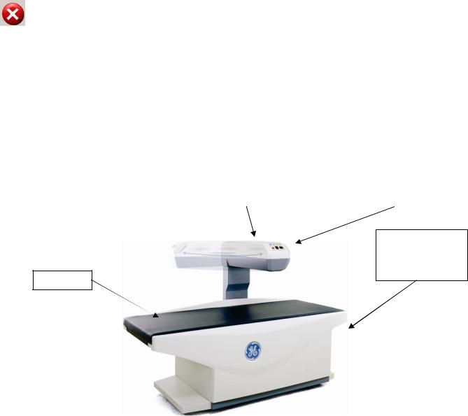
The DPX Bravo and Duo models use pencil beam technology with a single-crystal detector and have a compact table design to provide space efficiency (see images below).
The DPX Duo and the DPX Bravo come equipped with a scan arm that swings to the side of the table when not in use when not in use as a densitometer and to facilitate patient loading. X-ray scanning is not possible until the scan arm is locked into the scan position. A handle releases the scan arm interlock and allows operator to move the scan arm for patient loading. Once the patient is loaded on the table, the operator moves the scan arm back to scanning position and the arm locks into scan position. If a scan is attempted without the scan arm locked into position, the following error will be displayed:
Error Description:
Swing arm not locked in scanning position. Please lock before continuing.
Corrective Action:
Please try again. If the problem persists, contact GE Lunar Support for assistance.
To retract the scan arm once the scan is completed, home the scan arm.
Pull the lever on the front of the scan arm towards you and push the scan arm to the left until it rests along the back of the scanning table. The patient can then sit up and the table is free of obstruction.
The power switch is located at the head of the table. There is also a roll at the head of the table to store up to 21” x 3” (53.34 cm x 7.62 cm) exam paper. The table weight limit is 159 kg (350 pounds).
Swing Scan Arm |
|
|
|
Scan Arm Control Panel |
|
|
|
|
Exam Paper Roll
and Power Switch (head of scanner--
not shown)
Table Pad
DPX-Bravo
The DPX-Duo model also has mechanical features including stirrups, procedure drawer, storage drawers, and patient step to allow use as an exam table when bone densitometry is disabled and the scan arm is rotated and locked parallel to the table.
Page 8 of 138

Stirrups
Storage
Drawers
Patient Step
Swing Scan Arm (in scanning position)
Table Pad |
|
Scan Arm Control Panel |
|
|
|
Exam Paper Roll and Power Switch (head of table--not shown)
Procedure Drawer
DPX-Duo
Product Model
DPX-Pro/NT/MD+
DPX-Pro/NT/MD+ models come in full and compact sizes and use pencil beam technology with a single-crystal channel NaI detector. The power switch is located on the lower front panel. The table weight limit is 136 kg (300 lbs).
Scan Arm |
|
|
|
Scan Arm |
|||
|
|
||
|
|
Control Panel |
|
|
|
|
Table Pad
Power Switch
Page 9 of 138
DPX-NT
Product Model
Prodigy Pro/Primo/Advance
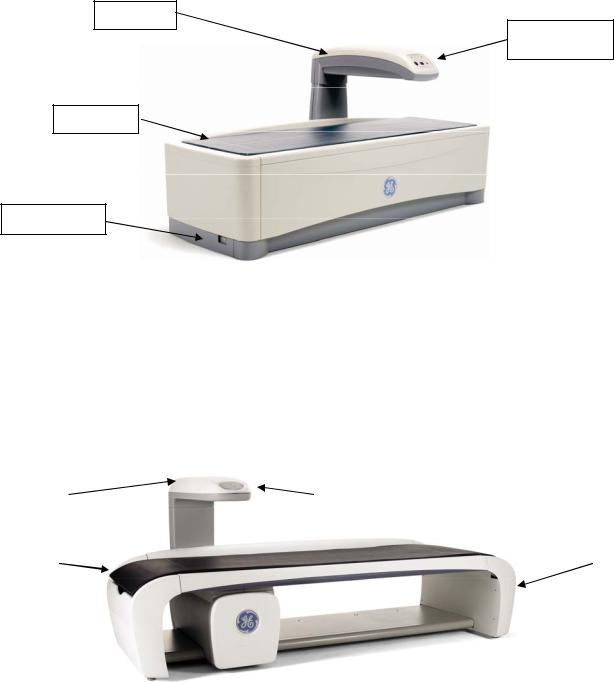
Prodigy models come in full and compact sizes and use fan beam technology with a 16-channel solid-state detector. The power switch is located at the foot of the scanner. The table weight limit is 159 kg (350 lbs).
Scan Arm
Scan Arm
Control Panel
Table Pad
Power Switch
Prodigy Series
Product Model iDXA
The Lunar iDXA uses fan beam technology with a 64-channel solid-state detector and is a scanner designed for optimal image quality and supports patient's weights to 204 kg (450 lbs).
The power switch and exam paper roll is located at the head of the scanner.
|
Scan Arm |
|
Scan Arm Control Panel |
|
|
|
|
|
|
Exam Paper Roll |
|||
|
|
|
|
|
|
|
|
|
|
|
|
|
and Power Switch |
|
|
|
|
|
|
(head of scanner- |
|
|
|
|
|
|
-not shown) |
Table Pad |
|
|
|
|||
|
|
|
|
|
||
|
|
|
|
|
||
|
|
|
|
|
|
|
iDXA
Page 10 of 138
The Warning label identifies the location of possible pinch points. When the scanner arm is in motion, make sure possible pinch point areas are clear at all times. The technologist must keep their feet away from the moving carriage. Patient limbs must remain inside the boundaries of the table top to avoid a pinch between the scanner arm and table.
Installation and Operation
Only individuals trained by GE Lunar should service or install the X-ray Bone Densitometer. Do not attempt to service the X-ray Bone Densitometer. Please call GE service or your GE distributor for support.
Before operating X-ray Bone Densitometer, please review the Safety and Technical Specification manual.
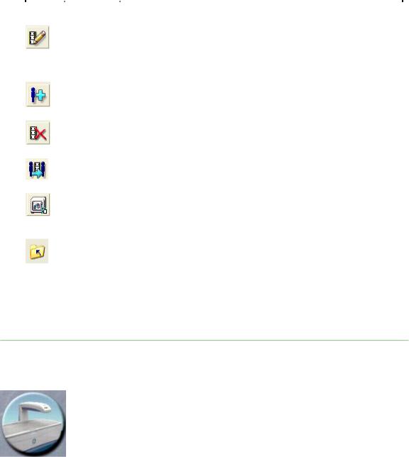
X-ray Bone Densitometer Table Assembly
Below “Scanner” is equal to “X-ray Bone Densitometer”
Scanner Table
The Scanner table is to support the patient during a measurement or general examination. In addition, the X ray source assembly and other electronics are contained inside the scanner table.
Scan Arm
The laser light, emitted from an aperture on the scanner arm, helps you locate the measurement start position. Positioning switches let you move the scanner arm until the laser light is located at the correct start position. The start position is different for each measurement type. The scanner arm on the DPX Duo and Bravo models has a release and locking mechanism allowing the upper arm to swivel when the scanner is idle. The scanner arm must be in the locked position over the scanner table to perform a measurement.
Scan arm control panel
Indicator Lights
Symbol |
Indicator |
Status (on) |
|
Green (power) |
Power is supplied to the scanner table |
|
|
|
|
Yellow (x-ray) |
X-ray tube assembly is supplying x-rays |
|
|
|
|
Yellow (shutter) |
Shutter is open |
|
|
|
|
Amber (laser) |
Laser is on |
|
|
|
|
|
Page 11 of 138 |
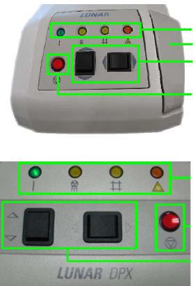
Emergency stop button
Push the red emergency stop button to stop the scanner arm and immediately shut down x-rays in an emergency. Do not use the emergency stop button to routinely stop the scanner during normal operation.
Positioning switches
The positioning switches move the scanner arm and detector to the measurement start position (the laser light indicates the position of the detector). The Back/Front switch moves the detector across the width of the scanner table. The Left/Right switch moves the scanner arm down the length of the scanner table.
Swing arm position sensing switches (DPX Duo and Bravo models only)
The swing arm position sensing switches detect the locking status of the swing arm and the swing arm latch. The swing arm latch must be locked and the swing arm must be in the locked position over the scan table before a measurement can be performed. Release of the swing arm latch during a measurement will abort the scan and the measurement data will be lost.
Scanner Start button (iDXA model only)
Once the patient has been positioned, the scan may be initiated from the green Start Scan button instead of starting the scan from the enCORE software.
See scan arm control panel for each model below:
Indicator Lights
Lever to lock/unlock Swing Arm
Positioning Switches
Emergency Stop Button
DPX Duo and Bravo
Indicator Lights
Emergency Stop Button
Positioning Switches
DPX-Pro/NT/MD+
Page 12 of 138
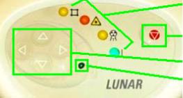
Indicator Lights
Emergency Stop Button
Positioning Switches
Start Scanner Button
iDXA Front Panel
The enCORE software is used to operate the X-ray Bone Densitometer, the following chapters describe how to use the enCORE software.
Note:
Daily Quality Assurance procedure
Complete quality assurance procedures daily. Make sure each QA procedure passes. Refer to Chapter 2 for detailed instructions. Make sure you save your printed results for future reference.
Archive image files
Archive your image files before you leave for the day. Refer to Chapter 5 for detailed instructions.
Shut down computer
At the end of the day, select Exit from the Main screen, and select Exit enCORE from the close window to close the program. Then shut down the computer. Note: Do not turn off the scanner at the end of the day for stationary systems.
Some of the functions of the enCORE are not available for all X-ray Bone Densitometer models.
Classifications
Protection against electric shock: Class I, Type B Protection against water: IPX0
Operation mode: continuous operation with intermittent loading
The device can neither be used in flammable anesthetic mixture with air or non flammable anesthetic mixture with oxygen or nitrous oxide.
Page 13 of 138

1.0Screens and Toolbars
1.1Overview
1.2Main Screen
1.3Analyze Screen
1.4Directory Screen
1.5New Measurement Screen
1.6Quality Assurance Screen
1.7Options
1.1 Overview
This section describes the screens and toolbars that are shown throughout the program. Screens and toolbars give the options necessary to complete the procedures given in this online Operator's Manual.
1.1.1 Using screens
The screens provide information that lets you set up and complete measurements, analysis, and quality assurance procedures. At the bottom of each screen, short descriptions of procedures and alternative keystrokes are given to help you complete a procedure.
1.1.2 Using toolbars
The toolbars show icons that represent a "tool" which lets you complete a specific procedure. To view a short description of a tool, hold the cursor stationary over the tool's icon.
1.1.3 Patient block
The Patient block is shown at the bottom of the Analyze, Directory, and New Measurement screens. The Patient block gives information about the patient that is being analyzed, measured, or is currently selected at the Directory screen. This is the same information you record in the Patient Information dialog box or select from the Patient list before starting a new measurement.
Page 14 of 138
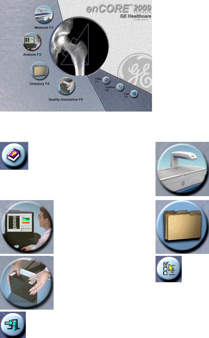
1.2 Main Screen
The Main screen is the first screen shown during the program. Select the options that follow to access different areas of the program:
|
Help (F1)– select to |
|
Measure (F2)–select to |
|
view additional |
|
start a patient |
|
reference information |
|
measurement. |
|
concerning the |
|
|
|
operation of the |
|
|
|
scanner. |
|
|
|
|
|
|
|
Analyze (F3)–select to |
|
Directory (F4)–select |
|
open a patient |
|
to work with your |
|
measurement for |
|
patient files and |
|
analysis. |
|
complete database |
|
|
|
maintenance |
|
|
|
procedures. |
|
|
|
|
|
Quality Assurance |
|
Options (F6)–select to |
|
(F5)–select to access |
|
change the User |
|
the Quality Assurance |
|
Options and |
|
(QA) screen. |
|
Connectivity Options |
|
|
|
default settings or to |
|
|
|
view the Error log. |
|
|
|
|
|
Exit (F8)–select to exit |
|
|
|
the program from the |
|
|
|
Main screen. |
|
|
|
|
|
|
Page 15 of 138
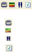
1.2.1 Common Toolbar
The Common Toolbar is shown on all screens.
Icon |
Program |
Description |
|
Measure |
Select to enter patient information or select a patient from |
|
(F2 or Ctrl+M) |
the database to start a new measurement. |
|
|
|
|
Analyze |
Select to choose an image file for analysis. |
|
(F3 or Ctrl+A) |
|
|
Directory |
Select to work with patient files and complete database |
|
(F4 or Ctrl+D) |
maintenance procedures. |
|
QA |
Select to start a Quality Assurance (QA) test. |
|
(F5 or Ctrl+Q) |
|
1.3 Analyze Screen
 The Analyze screen is used to analyze image files. This screen is shown when you select Analyze from the Common toolbar or the main screen or when you select an image file for analysis from the Directory screen.
In addition, this screen is shown immediately after a patient measurement if the "Analyze When Done" option is selected at the New Measurement screen.
1.3.1 Results Tabs
The data that follows is included in the Results tabs for image files:
•ScanCheck™ tab–provides a checklist of items to confirm and/or correct during analysis
•Densitometry tab–provides BMD, BMC, and Area for each region of the scan
•Trend tab–provides results trending over time
•Information tab–gives information related to the scan parameters.
•Composition tab- Total Body composition or Spine/Femur estimated composition
•AHA tab–Femur Advanced Hip Assessment, gives information about hip axis length and hip strength results.
•Morphometry tab. (Refer to LVA analysis or APVA analysis for more information.)
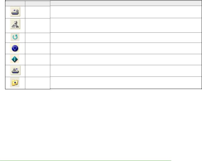
1.3.2Analyze toolbar
Select tools from the Analyze toolbar to complete analysis procedures. Refer to specific scan types for detailed analysis recommendations for each measurement site.
Page 16 of 138

General Analysis Tools
Icon |
Tool |
Description |
|
|
|
|
Imaging |
Select to adjust contrast and zoom the image file. |
|
|
|
(Ctrl+I) |
|
|
|
|
ROIs |
Select to position ROIs during analysis. Move and size ROI as well |
|
|
|
(Ctrl+R) |
|
|
|
|
Delete |
Use this option to delete an ROI |
|
|
|
ROI |
|
|
|
|
Move ROI |
This tool allows an ROI to be moved |
|
|
|
|
|
|
|
|
Rotate |
Select this tool to turn an ROI in a circular motion |
|
|
|
ROI |
|
|
|
|
Move |
Select this tool to move a vertex of an ROI |
|
|
|
Vertex |
|
|
|
|
Label |
May be used to label an ROI. |
|
|
|
ROIs |
|
|
|
|
Points |
Select to verify that bone and tissue samples are correctly classified. |
|
|
|
(F4) |
DO NOT adjust point typing unless the program made obvious |
|
|
|
|
errors. |
|
|
|
Reset |
This option is shown after you select Points. Select Reset to delete |
|
|
|
(F3) |
changes you made to point typing. |
|
|
|
Copy |
Use this option to copy ROIs from an existing image file to the |
|
|
|
(F5) |
current image file. |
|
|
|
Cancel |
This option is shown after you select ROIs or Points. Select Cancel |
|
|
|
(Esc) |
to delete changes you made to the image file. |
|
|
|
Results |
This option is shown after you select ROIs or Points. Select Results |
|
|
|
(Enter) |
to view analysis results for the image file. |
|
|
|
Report |
Select to create analysis reports for the image file. |
|
|
|
(Ctrl+Shif |
|
|
|
|
t+P) |
|
|
|
|
Save |
Select to save the image file and data to the patient database. |
|
|
|
(Ctrl+S) |
|
|
|
|
Close |
Select to close the image file. |
|
|
|
(Esc) |
|
|
ROI Tools |
|
|
|
|
Icon |
|
ROI Tool |
Description |
|
|
|
ROIs |
Select to position ROIs during analysis. Move and size ROI as well |
|
|
|
(Ctrl+R) |
|
|
|
|
Delete ROI |
Use this option to delete an ROI |
|
|
|
|
|
|
|
|
Move ROI |
This tool allows an ROI to be moved |
|
|
|
|
|
|
|
|
Rotate ROI |
Select this tool to turn an ROI in a circular motion |
|
|
|
|
|
|
|
|
Add ROI |
AP Spine |
|
|
|
|
|
|
|
|
Move |
Select this tool to move a vertex of an ROI |
|
|
|
Vertex |
|
|
|
|
Label ROIs |
May be used to label an ROI. |
|
|
|
|
|
|
|
|
Cancel |
This option is shown after you select ROIs or Points. Select Cancel |
|
|
|
(Esc) |
to delete changes you made to the image file. |
|
Page 17 of 138

Imaging Tools
Icon |
Image |
Description |
|
Tool |
|
|
Imaging |
Select to adjust contrast and magnify the image file. |
|
(Ctrl+I) |
|
|
Points |
Select to verify that bone and tissue samples are correctly |
|
(F4) |
classified. DO NOT adjust point typing unless the program made |
|
|
obvious errors. |
|
Reset |
This option is shown after you select Points. Select Reset to delete |
|
(F3) |
changes you made to point typing. |
|
Copy |
Use this option to copy ROIs from an existing image file to the |
|
(F5) |
current image file. |
|
Cancel |
This option is shown after you select ROIs or Points. Select Cancel |
|
(Esc) |
to delete changes you made to the image file. |
|
Results |
This option is shown after you select ROIs or Points. Select |
|
(Enter) |
Results to view analysis results for the image file. |
|
Report |
Select to create analysis reports for the image file. |
|
(Ctrl+Shif |
|
|
t+P) |
|
|
Save |
Select to save the image file and data to the patient database. |
|
(Ctrl+S) |
|
|
Close |
Select to close the image file. |
|
(Esc) |
|
|
|
|
1.4 Directory Screen
 The Directory screen is shown when you select Directory from the Main screen or from the Common toolbar. This screen lists the patient files and images that are stored in the active database.
The Directory Screen is divided into four areas:
1)Search Option
2)Patient List
3)Image List
4)Database Sidebar
Page 18 of 138
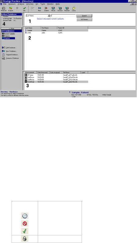
1.4.1 Search
Use the Search option to quickly locate a patient record and image file in a large database. The Search option is located near the top of the Directory screen.
1.Select the database field to use in the search (1).
2.Enter the patient information to use in the search (2).
3.Select Search. The patient record and associated image files are shown in the Patient and Image lists.
The All Patients button clears the search criteria and lists all the patients in the database.
1.4.2Patient and Image lists
Use the Patient and Image lists to select a patient to measure or an image file to analyze. Double-click on a highlighted patient record to start a new measurement, or double-click on a highlighted image file to analyze the image file.
•Patient list: The Patient list shows patient records in the database according to the patient’s last name, first name, and ID. The patient information for the selected patient is also shown in the Patient block at the bottom of the Directory, New Measurement, and Analyze screens.
•Image list: The Image list shows the measurement images recorded for a patient according to measurement type, date measured, date analyzed, file name, and label. The image list may include exams made up of multiple measurement images. Assign a status or notes to an exam by right-clicking on the exam in the directory and selecting Change Status or Notes. Choose from a list of 5 status types:
Icon |
Status |
No Icon |
Not Reviewed |
|
Pending Review |
|
|
|
Rejected |
|
|
|
Approved |
Closed
Enable Exam Status/notes features and set defaults, actions when sending a report, and status colors under Tools/User Options/Directory/Directory Status.
1.4.3 Database Sidebar
The Database sidebar shows the database that is currently being used (active database) and the working path of that directory. The Active Database panel indicates the location of the database and the drive used for archiving patient studies. Most systems will use a hard drive location for the working path
Page 19 of 138
and a removable media drive for the archive drive. This information is always available on the Directory screen.
All Databases are presented on the database sidebar. Creating more than one database is especially useful for customers performing research studies. The database currently active is highlighted in the available databases list. To change databases, highlight the desired database from the list.
The lower portion of the Database sidebar shows all available databases, and database maintenance options. If you do not see this information, select More >>.
Database Maintenance tools provide the ability to edit, create, rebuild or compress the database. Refer to Edit Database, Compress Database, or Rebuild Database, New Database, for additional information.
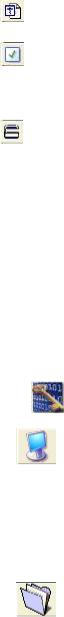
1.4.4 |
|
Directory toolbar |
|
||
|
The Directory toolbar displays options that let you work with your patient files. |
||||
|
|
|
|
|
|
|
|
Icon |
|
Tool |
Description |
|
|
|
|
Edit |
Select to edit Primary, Secondary, and Additional data for the |
|
|
|
|
Patient |
highlighted patient record in the Patient list. The edits are not |
|
|
|
|
(Ctrl+E) |
saved to image files that have already been acquired for the |
|
|
|
|
|
patient. Use the Edit Image tool to edit information for individual |
|
|
|
|
|
image files. |
|
|
|
|
New |
Enter a new patient that is not in the patient database. |
|
|
|
|
(Ctrl+N) |
|
|
|
|
|
|
|
|
|
|
|
Delete |
Select to delete the highlighted patient, exam, or image file. You |
|
|
|
|
(Del) |
can delete the patient, exam, or image record(s), or the record(s) |
|
|
|
|
|
and related exam or image file(s). |
|
|
|
|
|
|
|
|
|
|
Move |
Select to move exam to another patient record. |
|
|
|
|
(F4) |
|
|
|
|
|
|
|
|
|
|
|
Archive |
Select to copy or move exam files from the computer hard |
|
|
|
|
(F5) |
drive to an archive location. You can archive single exams, |
|
|
|
|
|
single patients, or all patients. You can also archive all exams |
|
|
|
|
|
for all patients found during a search. |
|
|
|
|
Close |
Select to exit the Directory screen. |
|
|
|
|
(Esc) |
|
|
|
|
|
|
|
1.4.5 |
|
Help Text |
|
|
|
Help Text is located in the lower left corner of every screen in enCORE™ software. The Help Text provides keystroke functionality, current operation of the system, and instructions for the software user.
1.5 New Measurement Screen
The New Measurement screen is used to complete a new measurement for an existing patient (recorded in the database) or for a new patient. This screen is shown or when you select Measure from the Common toolbar.
Page 20 of 138
A list of applicable measurement sites is presented on the New Measurement screen. The user may select the measurement site from the Exam List or highlight the measurement region on the corresponding Skeletal Image.
1.5.1 "Analyze When Done" option
Select the "Analyze When Done" option if you want to analyze the image file after the measurement: the Analyze screen is shown immediately after the measurement is complete.
1.5.2 Patient and laser position graphic
When you select Position from the New Measurement toolbar, a graphic is shown which illustrates the correct patient and laser position for the measurement type. (The laser is not used for total body measurements.) Review Measurement Procedure for further information on the appropriate laser starting position.
Page 21 of 138
1.5.3 New Measurement Toolbar
Icon Tool
Home
(F3)
Set Up
(F6)
Repeat
(F4)
Abort
(F5)
Start
(F7)
Position
(F7)
Close
(F8)
Description
Select to move the scanner arm to the Home position.
This option is shown after you select Position. Select Set Up to return to the set up screen and change the settings for the measurement. In addition, use this option to select a different measurement type and start a new measurement.
This option is shown after you complete an exam. Select Repeat to reposition the image and repeat the measurement.
Select to stop the measurement and save, continue (resume), or start a new measurement.
This option is shown after you select Position. Select Start to start the measurement.
Select to move the scanner arm to the start position; then, use the controls on the scanner arm to position the laser light for the measurement.
Select to exit the New Measurement screen.
1.5.4 Home scanner arm
Select Home Scanner (Ctrl + H) from the Measure menu to move the scanner arm to the home position from any screen in the program.
 Note: If the scan arm has been set to Home at the foot end of the table, and the foam leg block is used for AP Spine measurement, a warning will appear. Please remove patient positioner.
1.5.5 Park Scanner
Select Park Scanner (Ctrl+K) from the Measure menu to move the scan arm on a mobile system to the foot of the table for lockdown.
Page 22 of 138
1.6 Quality Assurance screen
 The Quality Assurance screen is used to complete a Quality Assurance (QA) procedure. This screen is shown when you select Quality Assurance from the Main screen or from the Common toolbar.
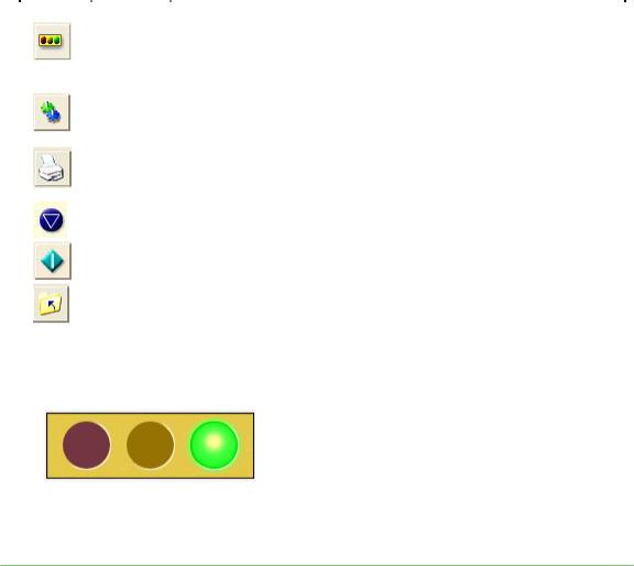
1.6.1 Quality Assurance Toolbar
Icon |
Tool |
Description |
|
|
Trend |
QA trending history is automatically shown after a QA procedure |
|
|
(F2) |
(unless you have changed this behavior in the User Options). If the |
|
|
|
trending history is not shown, you can select Trend to view the QA |
|
|
|
trending history after you complete the QA procedure. |
|
|
Setting |
Select to change information for trending. |
|
|
s |
|
|
|
(F3) |
|
|
|
Report |
Select to create a report of the QA results. |
|
|
(Ctrl+P |
|
|
|
) |
|
|
|
Abort |
Select to stop the QA test. |
|
|
(F5) |
|
|
|
Start |
Select to start the QA procedure. |
|
|
(Enter) |
|
|
|
|
|
|
|
Close |
Select to exit the QA screen. |
|
|
(Esc) |
|
|
|
|
|
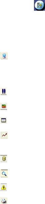
1.6.1 System Status
The Quality Assurance screen indicates the current operating status of the system. The System Status should indicate 'System is ready to measure patients' before performing patient measurements to ensure accurate results.
Refer to the topic Quality Assurance for instructions on performing a quality assurance procedure.
Page 23 of 138
1.7 Options
Select Options from the Main screen or select the Tools menu to access User Options, Connectivity Options, and the Error Log.
1.7.1 User Options
User Options let you set and change the program default settings.
Select Options |
(F6) from the |
|
Select the Tools menu and select User |
|
OR |
Options. |
|||
Main screen and select User Options. |
||||
|
|
|||
Change the necessary default setting(s).
Select OK to save changes. If you do not want to save changes, select Cancel.
User Options |
Description |
|
|
Systems |
This tab lists scanner System ID number and Feature code. User Interface Options, |
|
Exam File Options and ISCD settings.If the Automatic return to Directory option |
|
is selected, you will return to the Directory screen instead of the main screen when |
|
you close windows. The Auxiliary Workstation option is shown if you purchased the |
|
Multi-User Database kit. Select this option to prevent the workstation from performing |
|
QA procedures or patient measurements. The Number of Open Exams option lets |
|
you choose how many exams can be opened for analysis at the same time. |
|
|
Directory |
Use this option to determine how information is sorted in the Patient and Exam/Image |
|
lists and to configure default ethnicity. You can also choose to expand exams by |
|
default. |
Analyze |
Enable/Disable analysis features for all scan types. |
|
You can also choose the type of Small Animal calibration to use and the type of |
|
forearm calibration to use for BMD results. |
Results Display |
The Results Display tab lets you change the appearance of graphs; Standard, WHO |
|
or JSBMR. You can select the information shown in the results tables, select the |
|
composition results to show, and set the Morphometry SD cutoffs. |
Trending |
Use this option to select the type of information shown on trending graphs and in |
|
trending tables, and configure the software to flag significant change. The |
|
integrated Precision Calculator Tool is also located within this option. |
|
|
Reference |
Use this option to select a reference population and show the reference sources on |
Data |
the screen and the results reports. Use of the reference population comparisons is |
|
fully at the discretion of the clinician. The program does NOT show the |
|
comparative values when shipped from GE Medical Systems LUNAR. |
Image |
Use this option to set the colors of ROIs, bone edges, and point typed areas of an |
|
image file during analysis, and enable optimal image magnification. |
|
|
ScanCheck™ |
Use this option to select the ScanCheck™ checks that will be included on the |
|
ScanCheck™ tab for AP Spine, Femur, Forearm and Total Body analysis. |
|
|
Reports |
Select Patient ID types and Report background color. Under Dexa Report |
|
Configurations select to report on Selected Region Only, Trend Multiple Results, |
|
Invert Image, GE Healthcare Logo, Report Dialog, sBMD Footnote, Comments, Show |
|
Vertebral Height T-Scores, and Show Ethnicity. |
|
Change the Report Center Defaults- where the report will be sent, the types of |
|
reports that will be created, regions to be reported on, and the number of copies for |
|
each page of the report. |
|
User Information Includes the site name, address, phone numbers, web site and |
|
email information. |
|
|
|
Page 24 of 138 |
|
Morphometry Report Options are configured here. |
|
|
Composer |
Configure the file type to output from Composer. Use the Spelling Options to |
|
customize spell checker functions. |
|
|
QA |
Use this option to change the default setting for printing QA reports. |
|
Select Automatic Printing: Daily QA to have the program print a QA report each |
|
time you complete a quality assurance procedure. |
|
Select Automatic Return to Trend Screen to automatically return to the trend |
|
screen once a QA has completed. |
Measure |
Use this option to set the default settings used during a measurement. |
|
Save prompt at end of scan (select this option to show a message after every |
|
measurement that asks you if you want to save the measurement), Allow continue |
|
after SmartScan abort, Use Old Positioner for Lateral Measurements (Densitometry |
|
and Morphometry Only), Show Previous Scan, Allow Scanner Start Button to |
|
initiate a Measurement, LVA reverse (For LVA, scan patient facing foot of table), |
|
Default to seated patient for forearm and hand scans, Pause between Femur |
|
scans, OneScan™ (no Foam Leg Block positioner for AP Spine scans), or Pause |
|
between AP Spine and Femur Scans. |
2. Systems Tab
The scanner's System ID is unique. The System ID is needed for support.
The feature code is only compatible with your system ID. It enables the purchased options in your software. If you wish to try out a feature before buying it, contact your sales person for a trial feature code.
Icon |
Function |
Choices |
|
|
|
|
Additional |
Enter Trial and IRB feature codes. Expiration dates will display below |
|
Feature |
each feature code. |
|
Codes |
|
|
User |
Automatic return to Directory will return your display back to the |
|
Interface |
Directory scan after an acquisition is complete. |
|
Options |
HIPAA Secure View hides patients in the directory view. |
|
|
Play Multimedia Sounds option. |
|
|
Auxiliary Workstation for use with MUDBA setups. The Auxiliary |
|
|
Workstation option is shown if you purchased the Multi-User |
|
|
Database kit. Select this option to prevent the workstation from |
|
|
performing QA procedures or patient measurements. The Number of |
|
|
Open Exams option lets you choose how many exams can be opened |
|
|
for analysis at the same time. |
|
Exam |
HIPAA Secure Filename On: pat_z8gutml1w.dff |
|
File |
HIPAA Secure Filename Off: SmithJf0m485s.dff |
|
Options |
Compress Exam Files to conserve space for high resolution images such |
|
|
|
|
|
as iDXA scans. |
|
|
Encrypt Exam Files |
Page 25 of 138
ISCD Official Select "Yes" to accept the settings recommended by ISCD.
Position Review current ISCD Positions from the link in the enCORE software.
Acceptance
FRAX |
Check box(s) for ‘Enable FRAX’ and/or 'Apply US NOF/ISCD FRAX |
|
recommendations' |
|
Review the NOF/ISCD FRAX Implementation Guide from the link in the |
|
enCORE software for details. |
3. Directory Tab
Icon Function
Patient Sort
Options
Exam Sort
Options
Patient List
Columns
Directory
Rules &
Defaults
Directory
Status
Choices
Sort by First name, Last name or Patient ID
Ascending or Descending
Sort by Measurement, Date Measured, Date Analyzed, File Name, Archive, Import, or Status
Ascending or Descending
Choose Patient Third column contents:
Patient ID, Facility ID, Department ID or Exam ID
When duplicate patients occur follow Duplicate Patient Match Rule. Select Default Gender, Default Ethnicity, Duplicate Patient Match Rule:
Use Patient Last Name & Birthdate or Use Patient ID.
Checkbox Option to Expand Exams view in the directory by Default.
Enable Exam Status/notes features. Also, set defaults, actions when sending a report, and status colors.
Page 26 of 138
4. Analyze Tab
Icon Function
Femur Analysis
Options
Total Body
Analysis
Options
Forearm
Analysis
Options
Orthopedic
Analysis Options
Small
Animal/Research
Options
Morphometry
Options
Finish Button
Options
Estimated Total
Body
5. Results Display Tab
Choices to Appear in the Results
AHA: Hip Axis Length, Upper Neck region, Lower Neck region, Calculate Hip Strength results and Hip Geometry results
Calculate Left and Right results
Calculate Total Body Less Head (TBLH) result (used for Pediatric)
Forearm Calibration: Lunar, SPA or Comac
Standard Gruen zones or Extended Gruen zones
Calibration: Chemical/Ash or Lunar
Create ROIs on Request (Recommended) Automatically create Reference ROIs when needed Automatically create ROIs for T8-L4 when opening exam
Finish Button On/Off
Operation to perform: Send Report(s) to destinations, Save Exam and Close Exam
Estimate % Body Fat from Spine/Femur scan On or Off
Icon |
Function |
Choices |
|
|
|
|
Reference Graph |
Young Adult (YA) Bars: Standard SD, WHO or JSBMR |
|
Options |
Show Y2-axis values |
|
|
Age-Matched (AM) Bars appearance and SD applied |
|
Densitometry Table |
Young Adult (YA) in % or T-Score, Age-Matched (AM) in % or |
|
Options |
T-Score. |
|
|
Show BMC, Show Area, Show Diagnostic Category Icons |
|
|
and Show All DualFemur Regions |
|
Composition Options |
Z-Score or Centile Results |
|
|
Metric or English measurement system |
|
|
|
|
Morphometry |
Reference in Z-Score or Percent Height Reduction |
|
Reference Options |
Configuration for assigning deformity Mild, Moderate and Severe |
|
|
|
|
BMI Options |
BMI cut-off points assigned per WHO or Custom |
|
|
BMI On or Off |
|
|
|
Page 27 of 138
6. Trending Tab
Icon |
Function |
|
|
Choices |
|
|
|
|
|
|
|
|
Trend Graph Options |
Select Line Pattern, Densitometry Trend Graph, Morphometry |
|||
|
|
|
|
Trend Graph, or Composition Trend Graph settings. |
|
|
|
|
|
|
|
|
Trend Table Options |
Flag Significant Change On or Off. Configure how trending is |
|||
|
|
|
|
to be displayed. |
|
|
|
|
|
|
|
|
Precision Calculator |
A complete Precision Tool to determine Least Significant |
|||
|
|
|
|
Change (LSC) for scan types: AP Spine, Femur, DualFemur, |
|
|
|
|
|
Total Body, Forearm, Hand and Lateral Spine |
|
|
Choice of Measures |
For Densitometry Pediatric, Densitometry Adult, |
|||
|
to Trend On |
|
|
Morphometry, Composition Y1 axis, Composition Y2 axis, |
|
|
|
|
|
Estimated Composition Trend, and Pediatric Growth Trend. |
|
7. Reference Data Tab |
|
|
|
|
|
|
|
|
|
|
|
Function |
|
|
Choices |
|
|
|
|
|
Asia, Australia (Combined Geelong/Lunar), Australia (Geelong), |
||
Choice of Reference |
|
||||
Population |
|
Australia (Lunar), Brazil, China, Egypt, Finland, France, Germany, |
|||
|
|
|
Indonesia, Italy, Japan, Korea, Mexico, Middle East, Philippine, |
||
|
|
|
Spain, Tunisia, Turkey, UK, USA (Combined BMDCS/Lunar), USA |
||
|
|
|
(Combined NHANES/BMDCS/Lunar), USA (Combined |
||
|
|
|
NHANES/Lunar), USA (Lunar) |
||
Scan Site |
|
|
AP Spine, Femur, LVA, Total Body, Forearm or Lateral Spine |
||
|
|
Choose the region that will be the default region for analysis for each |
|||
Choice of Default Region |
|
||||
for Each Scan Type |
|
scan type |
|||
|
|
|
|
|
|
8. Image Tab
Icon Function
Image Options
Image Colors
Image Export
Options
Morphometry
Wizard Options
9. ScanCheck™ Tab
Choices
On or Off for: Interpolation, Invert Image, Show bone edges, Show Artifacts, Size Image to Fit screen on Open.
Display On or Off: Two Total Body images, Dual Femur Images top/bottom, Composition Image for Total Body.
Change image colors for ROIs, Zoom Region/Masks, Bone Edges, Point Typing, Markers and Artifacts
JPG Quality set
LVA Wizard Zoom Margin set in millimeters
Select the ScanCheck™ items that you would like to show in the analysis screen.  ScanCheck™ On or Off
Page 28 of 138

 Set ScanCheck™ view to appear first when analyzing
 Include ScanCheck™ indications on report.(bottom of screen)
Show |
AP Spine |
Detect the following problems |
|
|
Alert |
|
|
|
Measure |
Correct scan mode used? |
|
|
Technique |
|
|
|
|
|
|
|
|
|
AP Spine alignment reasonably straight? |
|
|
|
|
|
Analysis |
Optimal contrast and brightness set? |
|
|
Technique |
|
|
|
|
|
ROIs properly defined? |
|
|
|
|
|
|
|
L1-L4 labeled correctly? |
|
|
|
|
|
|
|
Tissue region properly defined? |
|
|
|
|
|
|
|
Bone edges properly defined? |
|
|
|
|
|
|
|
Results consistent with previous scan? |
|
|
|
|
|
Anatomy |
Analysis region free of unusual high density bone? |
|
|
Issues |
|
|
|
|
|
|
|
|
|
Free of unusual T-Score variation? |
|
|
|
|
|
|
|
Free of unusual curvature? |
|
|
|
|
|
|
|
AP Spine - Comments: |
|
|
|
|
|
|
|
|
Show |
Femur Alert |
|
Detect the following problems |
|
|
|
|
|
Measure |
|
Correct scan mode used? |
|
Technique |
|
|
|
|
|
Sufficient pelvis and shaft separation? |
|
|
|
|
|
|
|
Femur shaft reasonably straight? |
|
|
|
|
|
|
|
Proper femur rotation? |
|
|
|
|
|
Analysis |
|
Optimal contrast and brightness set? |
|
Technique |
|
|
|
|
|
ROIs properly defined? |
|
|
|
|
|
|
|
Tissue region properly defined? |
|
|
|
|
|
|
|
Bone edges properly defined? |
|
|
|
|
|
|
|
Results consistent with previous scan? |
|
|
|
|
|
Anatomy Issues |
Analysis region free of unusual high density bone? |
|
|
|
|
|
|
|
|
Page 29 of 138 |

|
|
|
|
Femur - Comments: |
|
||
|
|
|
|
|
|
|
|
|
|
|
|
|
|
|
|
|
Show |
Total Body Alert |
Detect the following problems |
|
|||
|
|
|
|
|
|
|
|
|
|
Measure |
Correct scan mode used? |
|
|||
|
|
Technique |
|
|
|
|
|
|
|
|
|
Patient within scan field? |
|
||
|
|
|
|
|
|
|
|
|
|
Analysis |
Optimal contrast and brightness set? |
||||
|
|
Technique |
|
|
|
|
|
|
|
|
|
ROIs properly defined? |
|
||
|
|
|
|
|
|
|
|
|
|
|
|
Patient Height Entered Correctly? |
|||
|
|
|
|
|
|
|
|
|
|
|
|
Patient Weight Entered Correctly? |
|||
|
|
|
|
|
|
|
|
|
|
Anatomy Issues |
Analysis region free of unusual high density bone? |
||||
|
|
|
|
|
|
|
|
|
|
|
|
Total Body - Comments: |
|||
|
|
|
|
|
|
|
|
|
|
|
|
|
|
|
|
|
Show |
Forearm Alert |
Detect the following problems |
|
|||
|
|
|
|
|
|
|
|
|
|
Measure |
Forearm alignment reasonably straight? |
|
|
||
|
|
Technique |
|
|
|
|
|
|
|
Analysis |
Optimal contrast and brightness set? |
|
|||
|
|
Technique |
|
|
|
|
|
|
|
|
|
ROIs properly defined? |
|
||
|
|
|
|
|
|
|
|
|
|
|
|
Tissue region properly defined? |
|||
|
|
|
|
|
|
|
|
|
|
|
|
Bone edges properly defined? |
|||
|
|
|
|
|
|
|
|
|
|
Anatomy Issues |
Analysis region free of unusual high density bone? |
||||
|
|
|
|
|
|
|
|
|
|
|
|
Forearm - Comments: |
|||
|
|
|
|
|
|
|
|
10. Report Tab |
|
|
|
|
|
|
|
|
|
|
|
|
|
||
|
Icon |
|
Function |
|
Choices |
||
|
|
|
|
|
|
||
|
|
|
Report Patient ID |
|
Patient Name, Patient ID, Facility ID, Dept ID, Exam ID, |
||
|
|
|
Types |
|
Attendant, Referring Physician, Reading Physician or blank. |
||
|
|
|
|
|
|
||
|
|
|
Report Colors |
|
Change the background color of DXA Reports |
||
|
|
|
|
|
|
||
|
|
|
DXA Report |
|
Selected Region Only, Trend Multiple Results Only, Invert Image, |
||
|
|
|
Configuration |
|
Show GE Healthcare Logo, Show Report Dialog, sBMD Footnote |
||
|
|
|
|
|
on, Show Comments, Show Vertebral Height T-Score, Show |
||
|
|
|
|
|
Ethnicity |
||
|
|
|
Report Center |
|
Opens the Report Center Window for configuration. See |
||
|
|
|
Defaults |
|
Report Center Chapter for more information. |
||
|
|
|
|
|
|
||
|
|
|
Report Regions |
|
Select the regions desired for each scan type. "Selected |
||
|
|
|
|
|
Region" will report the region currently highlighted on screen |
||
|
|
|
|
|
|
||
|
|
|
|
|
Page 30 of 138 |
||
 Loading...