

Page 1

LN-520
Digital A/V Receiver
Page 2
www.gateway.com
1
READ THIS BEFORE OPERATING YOUR UNIT
: TO REDUCE THE RISK OF
ELECTRIC SHOCK, DO NOT
REMOVE COVER (OR BACK). NO
USER-SERVICEABLE PARTS
INSIDE. REFER SERVICING TO
QUALIFIED SERVICE PERSONNEL.
: TO REDUCE THE RISK OF FIRE OR ELECTRIC SHOCK,
DO NOT EXPOSE THIS APPLIANCE TO RAIN OR MOISTURE.
Units shipped to the U.S.A and Canada are designed for operation on 120 V AC only.
Safety precaution with use of a polarized AC plug.
However, some products may be supplied with a nonpolarized plug.
FOR YOUR SAFETY
U.S.A
CANADA
120 V
Note to CATV System Installer :
This reminder is provided to call the CATV system installer’s attention to Article 820-40 of the NEC
that provides guidelines for proper grounding and, in particular, specifies that the cable ground shall
be connected to the grounding system of the building, as close to the point of cable entry as pracitcal.
•
Avoid high temperatures. Allow for sufficient heat dispersion when installed on a rack.
•
Keep the set free from moisture, water, and dust.
•
Do not let foreign objects in the set.
•
Handle the power cord carefully. Hold the plug when unplugging the cord.
•
Unplug the power cord when not using the set for long periods of time.
•
Do not obstruct the ventilation holes.
•
Do not let insecticides, benzene, and thinner come in contact wth the set.
•
Never disassemble or modify the set in any way.
FCC INFORMATION
This equipment has been tested and found to comply with the limits for a Class B digital device,
pursuant to Part 15 of the FCC Rules. These limits are designed to provide reasonable protection
against harmful interference in a residential installation. This equipment generates, uses and can
radiate radio frequency energy and, if not installed and used in accordance with the instructions, may
cause harmful interference to radio communications. However, there is no guarantee that interference
will not occur in a particular installation. If this equipment does cause harmful interference to radio or
television reception, which can be determined by turning the equipment off and on, the user is
encouraged to try to correct the interference by one or more of the following measures:
Reorient or relocate the receiving antenna.
Increase the separation between the equipment and receiver.
Connect the equipment into an outlet on a circuit different from that to which the receiver is
connected.
Consult the dealer or an experienced radio/TV technician for help.
CAUTION
WARNING
: To prevent electric shock, match wide blade of plug to wide slot, fully
insert.
: Pour éviter chocs électriques, introduire la lame la plus large de la
fiche dans la borne correspondante de la prise et pousser jusqu’ au
fond.
CAUTION
ATTENTION
This symbol is intended to alert the user to the
presence of uninsulated "dangerous voltage"
within the product's enclosure that may be of
sufficient magnitude to constitute a risk of
electric shock to persons.
This symbol is intended to alert the user to the
presence of important operating and
maintenance (servicing) instructions in the
literature accompanying the appliance.
INTRODUCTION
Page 3

www.gateway.com
2
1. Read Instructions - All the safety and operating instructions should
be read before the product is operated.
2. Retain instructions - The safety and operating instructions should
be retained for future reference.
3. Heed Warnings - All warnings on the product and in the operating
instructions should be adhered to.
4. Follow Insturctions - All operating and use instuctions should be
followed.
5. Cleaning - Unplug this product from the wall outlet before cleaning.
Do not use liquid cleaners or aerosol cleaners. Use a damp cloth for
cleaning.
6. Attachments - Do not use attachments not recommended by the
product manufacturer as they may cause hazards.
7. Water and Moisture - Do not use this product near water - for
example, near a bath tub, wash bowl, kitchen sink, or laundry tub; in
a wet basement, or near a swimming pool; and the like.
8. Accessories - Do not place this product on an unstable cart, stand,
tripod, bracket, or table. The product may fall, causing serious injury
to a child or adult, and serious damage to the product. Use only with
a cart, stand, tripod, bracket, or table recommended by the
manufacturer, or sold with the product. Any mounting of the product
should follow the manufacturer’s insturctions, and should use a
mounting accessory recommended by the manufacturer.
9. A product and cart combinaion should be moved with care. Quick
stops, excessive force, and uneven surfaces may cause the product
and cart combination to overturn.
10. Ventilation - Slots and openings in the
cabinet are provided for ventilation and
to ensure reliable operation of the
product and to protect it from
overheating, and these openings must
not be blocked or covered. The
openings should never be blocked by
placing the product on a bed, sofa, rug,
or other similar surface. This product should not be placed in a
built-in installation such as a bookcase or rack unless proper
ventilation is provided or the manufacturer’s intructions have been
adhered to.
11. Power Sources - This product should be operated only from the
type of power source indicated on the marking label. If you are not
sure of the type of power supply to your home, consult your product
dealer or local power company. For porducts intended to operate
from battery power, or other sources, refer to the operating
instructions.
12. Grounding or Polarization - This product may be equipped with a
polarized alternating-current line plug (a plug having one blade
wider than the other). This plug will fit into the power outlet only one
way. This is a safety feature. If you are unable to insert the plug
fully into the outlet, try reversing the plug. If the plug should still fail
to fit, contact your electrician to replae your obsolete outlet. Do not
defeat the safety purpose of the polarized plug.
Alternate Warnings - This product is equipped with a three-wire
grounding-type plug, a plug having a third(grounding) pin. This plug
will only fit into a grounding-type power outlet. this is a safety
feature. If you are unable to insert the plug into the outlet, contact
your electrician to replace your obsolete outlet. Do not defeat the
safety purpose of the gronding-type plug.
13. Power-Cord Protection - Power-supply cords should be routed so
that they are not likely to be walked on or pinched by items placed
upon or against them, paying particlar attention to cords at plugs,
convenience receptacles, and the point where they exit from the
product.
14. Outdoor Antenna Grounding - If an outside antenna or cable
system is connected to the product, be sure the antenna or cable
system is grounded so as to provide some protection against
voltage surges and built-up static charges. Article 810 of the
National Electrical Code, ANSI/NFPA 70, provides information with
regard to proper grounding of the mast and supporting structure,
grounding of the lead-in wire to an antenna discharge unit, size of
grounding conductors, location of antenna-discharge unit,
connection to grounding electrodes, and requirements for the
grounding electrode. See Figure 1.
15. Lightning - For added protection for this product during a lightning
storm, or when it is left unattended and unused for long periods of
time, unplug it from the wall outlet and disconnect the antenna or
cable system. This will prevent damage to the product due to
lightning and power-line surges.
16. Power Lines - An outside antenna system should not be located in
the vicinity of overhead power lines or other electric light or power
circuits, or where it can fall into such power lines or circuits. When
installing an outside antenna system, extreme care should be taken
to keep from touching such power lines or circuits as contact with
them might be fatal.
17. Overloading - Do not overload wall outlets, extension cords, or
integral convenience receptacles as this can result in a risk of fire
or electric shock.
18. Object and Liquid Entry - Never push objects of any kind into this
product through openings as they may touch dangerous voltage
points or short-out parts that could result in a fire or electric shock.
Never spill liquid of any kind on the product.
19. Servicing - Do not attempt to service this product yourself as
opening or removing covers may expose you to dangerous voltage
or other hazards. Refer all servicing to qualified service personnel.
20. Damage Requiring Service - Unplug this product form the wall
outlet and refer servicing to qualified service personnel under the
following conditions:
a) When the power-supply cord or plug is damaged,
b) If liquid has been spilled, or objects have fallen into the
product,
c) If the product has been exposed to rain or water,
d) If the product does not operate normally by following the
operating instructions. Adjust only those controls that are
covered by the operating instructions as an improper
adjustment of other controls may result in damage and will
often require extensive work by a qualified technician to
restore the product to its normal operation.
e) If the product has been dropped or damaged in any way, and
f) When the product exhibits a distinct change in performance -
this indicates a need for service.
21. Replacement Parts - When replacement parts are required, be
sure the service technician has used replacement parts specified
by the manufacturer or have the same characteristics as the
original part. Unauthorized substitutions may result in fire, electric
shock, or other hazards.
22. Safety Check - Upon completion of any service or repairs to this
product, ask the service technician to perform safety checks to
determine that the product is in proper operating condition.
23. Wall or Ceiling Mounting - The product should be mounted to a
wall or ceiling only as recommended by the manufacturer.
24. Heat - The product should be situated away from heat sources
such as radiators, heat registers, stoves, or other products
(including amplifiers) that produce heat.
F gure 1
Example of antenna grounding as per
National Electrical Code, ANSI/NFPA 70
ANTENNA
LEAD IN
WIRE
GROUND
CLAMP
ELECTRIC
SERVICE
EQUIPMENT
ANTENNA
DISCHARGE UNIT
(NEC SECTION 810-20)
GROUNDING CONDUCTORS
(NEC SECTION 810-21)
POWER SERVICE GROUNDING
ELECTRODE SYSTEM
(NEC ART 250, PART H)
NEC - NATIONAL ELECTRICAL CODE
GROUND CLAMPS
PORTABLE CART WARNING
Figure 1
Example of antenna grounding as per
National Electrical Code, ANSI/NFPA 70
SAFETY INSTRUCTION
Page 4

www.gateway.com
3
• Introduction
READ THIS BEFORE OPERATING YOUR UNIT | 1
• System Connections | 4
• Front Panel Controls | 8
• Universal Remote Controls | 9
OPERATING COMPONENTS WITH REMOTE CONTROL | 11
REMOTE CONTROL OPERATION RANGE | 11
LOADING BATTERIES | 11
USING FUNCTIONS OF REMOTE CONTROL | 12
• Before Operation
SURROUND SOUND | 15
• Operations
TURNING THE POWER ON/OFF | 20
LISTENING TO A PROGRAM SOURCE | 21
ENJOYING SURROUND SOUND | 23
LISTENING TO RADIO BROADCASTS | 30
ANALOG AUDIO/VIDEO RECORDING | 32
DIGITAL AUDIO RECORDING WITH MD RECORDER | 33
OTHER FUNCTIONS | 34
• Using the OSD
CURRENT STATUS DISPLAY | 35
MENU SCREEN | 35
• Troubleshooting Guide | 38
• Specifications | 39
• Appendix
INITIALIZING THE SYSTEM | 40
SETTING UP THE SYSTEM ON FRONT PANEL | 40
SETUP CODE TABLE | 42
• Warranty Booklet | 48
CONTENTS
Page 5
www.gateway.com
4
• Do not plug the AC input cord into the wall AC outlet until all connections are completed.
• Be sure to observe the color coding when connecting audio and video cords.
• Make connections firmly and correctly. If not, it can cause loss of sound, noise or damage to the receiver.
OPT 1
FM 75
ANTENNA
OPT 2
COAX
OPT
DIGITAL
OUT
DIGITAL IN
GND AM
7CH DIRECT INPUT
SUB-
WOOFER
OUT
FRONT SURROUND SURR.BACK
SUB WOOFERCENTER
TAPE
IN OUT
IN OUT
IN IN IN
VIDEO 1 VIDEO 2 VIDEO 3 AUX
VIDEOS-VIDEO
FRONT
SPEAKERS(6 )
SURROUND
SPEAKERS(6 )
CENTER
SPEAKER(6 )
SURR. BACK /
SUB WOOFER(6 )
41 58
3267
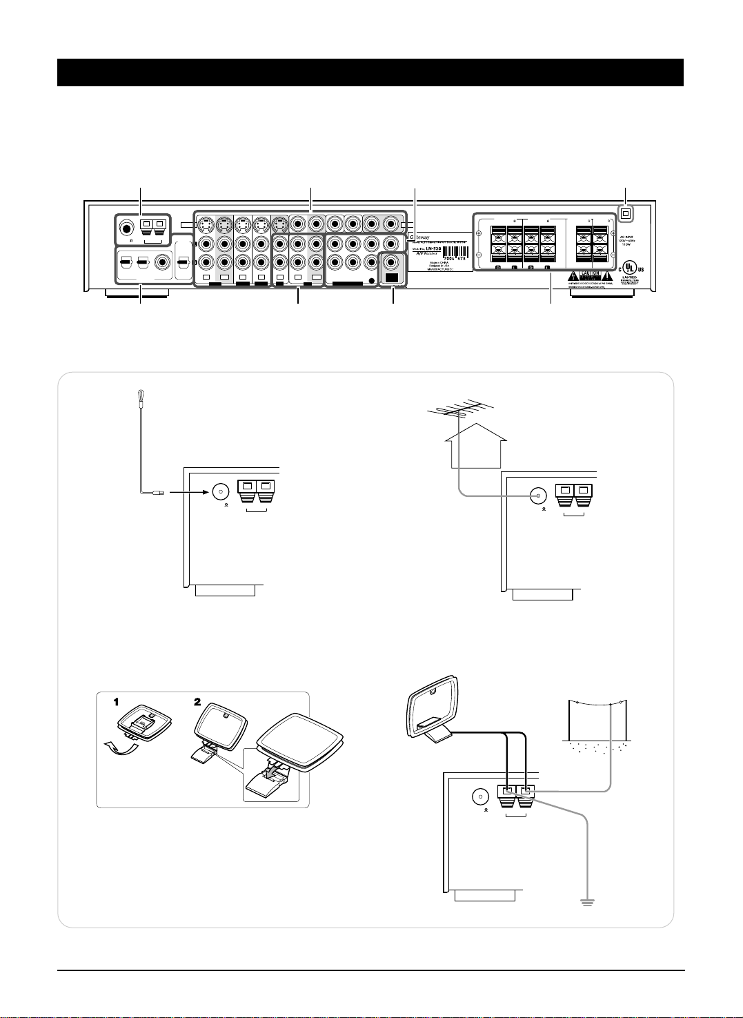
1.
CONNECTING ANTENNAs
FM 75
ANTENNA
GND AM
FM Indoor Antenna
• Change the position of the FM indoor antenna until you
get the best reception of your favorite FM stations.
FM 75
ANTENNA
GND AM
AM Loop Antenna
AM Outdoor Antenna
• Place the AM loop antenna as far as possible from the
receiver, TV set, speaker cords and the AC input cord
and set it to a direction for the best reception.
• If the reception is poor with the AM loop antenna, an AM
outdoor antenna can be used in place of the AM loop
antenna.
FM 75
ANTENNA
GND AM
FM Outdoor Antenna
• A 75Ω outdoor FM antenna may be used to further
improve the reception. Disconnect the indoor
antenna before replacing it with the outdoor one.
SYSTEM CONNECTIONS
Page 6

www.gateway.com
5
FRONT SURROUND SURR.BACK
SUB WOOFERCENTER
OUT
IN IN
7CH DIRECT INPUTVIDEO 1 VIDEO 2 VIDEO 3
TAPE
Tape deck, MD recorder, etc.
AUX
CD player, tape deck, etc.
AUDIO
OUT
R
L
L
R
L
R
AUDIO
OUT
AUDIO
IN
3. CONNECTING AUDIO COMPONENTS
• The AUX jacks may be connected to an additional audio component such as a CD player, a tape deck, etc.
• The TAPE IN/OUT jacks can be connected to PLAY(OUT) / REC(IN) jacks of MD recorder.
2. CONNECTING DIGITAL INs and OUT
• The COAXIAL or the OPTICAL DIGITAL OUTs of the components that are connected to AUX and VIDEO 1~3 of this unit can
be connected to these DIGITAL INs.
Component with
COAXIAL DIGITAL OUT
Component with
OPTICAL DIGITAL OUT
Component with
OPTICAL DIGITAL OUT
Component such as
an MD recorder, CD recorder
with OPTICAL DIGITAL IN
OPT 1 OPT 2
COAX
OPT
DIGITAL
OUT
DIGITAL IN
• If a digital recorder or other component with OPTICAL DIGITAL IN/OUT jacks is connected to the corresponding jacks of
this unit, you can playback and/or record the high quality
sound of CD’s, etc. without analog conversion or degradation.
• A digital input should be connected to the components such
as a CD player, LD player, DVD player, etc. capable ofoutputting DTS Digital Surround, Dolby Digital or PCM format
digital signals, etc.
• For details, refer to the operating instructions of the component connected.
• When making the COAXIAL DIGITAL connection, be sure to
use a 75Ω COAXIAL cord, not a conventional AUDIO cord.
• All of the commercially available optical fiber cords cannot be
used for the equipment. If there is an optical fiber cord which
cannot be connected to your equipment, consult your dealer
or nearest service organization.
4. CONNECTING VIDEO COMPONENTS
• This unit incorporates S-VIDEO and composite (normal) VIDEO jacks.
For your reference, the excellence in picture quality is as follows: “S-VIDEO” > composite(normal) “VIDEO”
• A signal input into the composite(normal) VIDEO IN jack will be output in the composite(normal) VIDEO OUT jacks and a
signal input into the S-VIDEO IN jack will be output in the S-VIDEO OUT jacks and the composite (normal) MONITOR 1/2
VIDEO OUT jacks.
• The next picture is different from your real back pannel; just for helping your understnading.
When you connecting the components on the real back pannel, refer to the sticker on top cover.
SYSTEM CONNECTIONS
Page 7

www.gateway.com
6
M
• The jacks of VIDEO 2/VIDEO 3 can also be connected to an
additional video component such as a cable TV tuner, an LD
player or satellite system.
• The jacks of VIDEO 1 may also be connected to a VCR,
DVD recorder or other digital video recording component.
For details, refer to the operating instructions of the
component to be connected.
VIDEO2 VIDEO3
IN IN IN 1 2
VIDEO
MONITOR
MONITOR
OUT
VIDEO1
MONITOR 1
TV, projector, etc.
S-VIDEO IN VIDEO
IN
MONITOR 2
Additional TV, projector, etc.
S-VIDEO IN
VIDEO
IN
SYSTEM CONNECTIONS
VIDEO 1 VCR, DVD player/recorder, etc.
VIDEO
AUDIO
AUDIOINS-VIDEO
OUT
RLRL
OUT
S-VIDEO
IN
VIDEO
OUT
IN
S-VIDEO
VIDEO 2
IN IN
IN IN
VIDEO 2 VIDEO 3
DVD player, VCR, etc.
AUDIO
S-VIDEO
OUT
RL
OUT
MONITOR
VIDEO
OUT
IN
VIDEO1
OUT
VI
VIDEO 3
DVD player, VCR, etc.
AUDIO
RL
OUT
S-VIDEO
OUT
VIDEO
OUT
IN INOUT
S-VIDEO
IN OUT
MONITOR
IN
VIDEO 3VIDEO 1
VIDEO1 VIDEO2
IN IN
OUT
EO 1
IN
OUT
VIDEO 2
MONITOR
VIDEO1 VIDEO2 VIDEO3
IN IN IN 1
OUTIN INOUT
Page 8

www.gateway.com
• Be sure to connect speakers firmly and correctly according
to the channel(left and right) and the polarity(+ and -). If the
connections are faulty, no sound will be heard from the
speakers, and if the polarity of the speaker connection is
incorrect, the sound will be unnatural and lack bass.
• For installing the speakers, refer to “Speaker placement” on
page 17.
• After installing the speakers, first adjust the speaker settings
according to your environment and speaker layout.(For
details, refer to “Adjusting the speaker settings” on page
18.)
Caution :
• Be sure to use the speakers with the impedance of 6 ohms
or above.
• Do not let the bare speaker wires touch each other or any
metal part of this unit. This could damage this unit and/or
the speakers.
7
5. CONNECTING 7 CH DIRECT INPUTS 7. CONNECTING SPEAKERS
8. AC INPUT CORD
6. SUBWOOFER PRE OUT connection
Subwoofer
Surround right
(Front)
center
Surround left
Front left Front right
Surround
back
• Plug this cord into a wall AC outlet.
IN
SURROUND
SUBWOOFER
FRONT
CENTER
7 CH DIRECT OUTPUT
Decoder with 6 or 7
channel outputs
RRLL BACK
• Use these jacks to connect the corresponding analog outputs of a DVD player or external decoder, etc. that has 6 or
7 channel outputs.
• In case of 6 channel outputs, do not connect this SURROUND BACK input to your component.(For details, refer
to the operating instructions of the component to be connected.)
• To emphasize the deep bass sounds, connect a powered
subwoofer.
• Note : When there is not surround back speaker, you can
connect the subwoofer into the terminal of surround back
speaker. In this case, you should change the subwoofer
speaker setting. Refer to “Adjusting the speaker settings” on
page 18.
SYSTEM CONNECTIONS
Page 9

www.gateway.com
8
FLUORESCENT DISPLAY
INPUT SELECTOR
AM/FM MODE
DIGITAL INPUT
MEMORY
SETUP
TUNE MODE
DECODING
PHONES
TUNING/PRESET
ADJUST VOLUME
POWER
ON/ OFF
STANDBY
1. Input, frequency, volume level,
operating information, etc.
2. Surround mode indicators
3. AUTO indicator
4. DIGITAL input signal indicator
5. PRESET number, SLEEP time,
Speaker distance display
6. MEMory indicator
7. DIRECT indicator
8. TUNED indicator
9. STEREO indicator
12 3456789
98 7
21345
6
1. POWER switch
2. STANDBY indicator
3. INPUT SELECTOR button
4. DIGITAL INPUT/AM/FM MODE button
• When digital signal(AUX, VIDEO1~3) is
inputted, this button functions as digital
input selector button.
• When tuner is selected, this button
functions as band selector button.
5. SETUP/MEMORY button
• When pressing this button for a seconds,
this button functions as setup button.
6. DECODING/TUNE MODE button
• In setting mode, this button functions as sub
mode button.
7. ADJUST/TUNING/PRESET UP(▲) /
DOWN(▼) buttons
• In setting mode, this button functions as
ADJUST button.
8. VOLUME UP(▲) / DOWN(▼) buttons
9. HEADPHONE jack
FRONT PANEL & REMOTE CONTROLS
Page 10

www.gateway.com
9
This universal remote control can operate not only this receiver but also most popular brands of audio and video
components such as CD players, cassette decks, TVs, cable boxes, VCRs, DVD players, satellite receivers, etc.
• To operate 7 components other than this receiver, you should enter the setup code for each component.
(For details, refer to “USING FUNCTIONS OF REMOTE CONTROL” on page 12.)
• The numbered buttons on the remote control have different functions in different device modes. For details, refer to
“FUNCTION TABLE of the NUMBERED BUTTONS” on the following page 10.
AUTO
12345
67890
T.TONE
DSP
STEREO
POWER
AUDIO
VCR
SPK SET
ADJUST
M1 M2 M3
AUDIO SEL.
OSD
SETUP
SLEEP
DISPLAY
DIMMER
RETURN
P.SCAN
TUNER CD AUX
VIDEO1 VIDEO2 VIDEO3
TAPE
7CH DIR.
+
10
TUNE
PRESET
ENTER
SUBTITLE ZOOM
VOLUME
MUTE
CH SEL.
T/V
CH/LEVEL
MACRO
DVD CABLE SAT
CD AUX TV
STANDBY
PL
PARA.
MENU
UNIVERSAL REMOTE CONTROL
RNC-40
1
8
2
3
4
5
11
12
14
17
15
20
10
13
21
POWER
LED
MACRO
To operate a macro function, press
the corresponding MACRO button.
DEVICE
To operate the desired component with
this remote control, first select the
corresponding DEVICE button.
SPEAKER SETUP
PL II MUSIC PARAMETER
ADJUST UP/DOWN (>,<)
AUTO
DSP MODE UP/DOWN ( , )
OSD
SLEEP
16
18
TUNING UP/DOWN(+,-)
NUMERIC(0~9, +10)
/ INPUT SELECTOR
To select the desired input
source of TUNER~VIDEO 3.
CHANNEL LEVEL UP/DOWN ( , )
CHANNEL SELECTOR
MUTE
VOLUME UP/DOWN( , )
STEREO
TEST TONE
CURSOR CONTROL ( , , , )
/ ENTER
DIMMER
PRESET SCAN
PRESET UP/DOWN (+,-)
7CH DIRECT
7
6
9
19
UNIVERSAL REMOTE CONTROLS
Page 11

www.gateway.com
10
FUNCTION TABLE of the NUMBERED BUTTONS
Device to be
controlled
Button symbol
(for CD player)
(for tape deck) (for VCR) (for DVD player)
(for satellite receiver)
0 9
POWER
+
10
STANDBY
P.SCAN
CH/LEVEL
VOLUME
OSD
SETUP
SLEEP
DISPLAY
DIMMER
RETURN
SUBTITLE
AUDIO SEL.
ZOOM
TUNE
PRESET
CH SEL.
T/V
MUTE
T.TONE
MENU
ENTER
1
2
3
4
5
6
7
8
9
10
11
12
13
14
15
16
17
18
19
20
CD AUX
(for TV)
TV VCR DVD
(for cable box)
CABLE SAT
POWER POWER POWER
MUTE
POWER POWER POWER POWER
PLAY
FORWARD PLAY
REVERSE PLAY
PAUSE
STOP STOP STOP
PLAY
PAUSE
RECORD RECORD
NUMERIC NUMERIC NUMERIC NUMERIC NUMERIC NUMERIC
REVERSE SKIP ( )
FORWARD SKIP ( )
REVERSE SKIP ( )
FORWARD SKIP ( )
REVERSE SEARCH ( )
FORWARD SEARCH ( )
REWIND ( )
FAST FORWARD ( )
REWIND ( )
FAST FORWARD ( )
STANDBY
(POWER OFF)
STANDBY
(POWER OFF)
STANDBY
(POWER OFF)
INPUT SELECTOR
CHANNEL LEVEL
UP/DOWN ( / )
CHANNEL LEVEL
UP/DOWN ( / )
VOLUME
UP/DOWN ( / )
MUTE
SUBTITLE
ZOOM
SETUP
MENU
ENTER
DISPLAY
RETURN
PLAY
PAUSE
STOP
INPUT SELECTOR
AUDIO SELECTOR
CURSOR CONTROL
VOLUME
UP/DOWN ( / )
CHANNEL LEVEL
UP/DOWN ( / )
MUTE
INPUT SELECTOR
VOLUME
UP/DOWN ( / )
CHANNEL LEVEL
UP/DOWN ( / )
MUTE
INPUT SELECTOR
VOLUME
UP/DOWN ( / )
STANDBY
(POWER OFF)
STANDBY
(POWER OFF)
STANDBY
(POWER OFF)
STANDBY
(POWER OFF)
21
Notes:
• Some functions for each component may not be available or may work differently.
• Depending on other kinds of components that are available for each DEVICE button, some functions may not be
available or may work differently, too.
• For details about functions, refer to the operating instructions of each component.
UNIVERSAL REMOTE CONTROLS
Page 12

www.gateway.com
11
12345
67890
+
10
M1 M2 M3
T/V
LOADING BATTERIES
REMOTE CONTROL OPERATION RANGE
1 2
• Use the remote control unit within a range of
about 7 meters (23 feet) and angles of up to 30
degrees aiming at the remote sensor.
OPERATING COMPONENTS WITH REMOTE CONTROL
• Remove the batteries when they are not used for a
long time.
• Do not use the rechargeable batteries(Ni-Cd type).
• Be sure to use alkaline batteries.
Remove the cover.
Load two batteries matching the polarity.
1
Enter the setup code for each component
other than this receiver you wish to
control. For details, refer to “Entering a
setup code” on page 12.
2
Turn on the component you want to
operate.
3
Press the DEVICE button on the remote
control corresponding to the component
you wish to operate.
4
Aim the remote control at the REMOTE
SENSOR of the component you wish to
control and press the button corresponding
to the operation you want.
• When the remote control does not operate, the old batteries should be replaced. In this case, load new batteries within
several minutes after removing old batteries.
• If the batteries are removed or have been exhausted for a longer period of time, memorized contents will be cleared.
Should this happen, you should memorize them again.
2×1.5V
(“AAA” size)
UNIVERSAL REMOTE CONTROLS
Page 13

www.gateway.com
12
Turn on the component you want to control
USING FUNCTIONS OF REMOTE CONTROL
Entering a setup code
• This remote control can control up to 8 different components.
• Before operating audio and video components other than this receiver with using this remote control, the setup
code for each component should be entered.
• For system remote control operation, “000” was stored previously in the memory of the device button “CD” for
Sherwood CD player, “DVD” for Sherwood DVD player and “AUX” for Sherwood tape deck respectively as its
factory setup code. So, you don’t need to enter its code for each Sherwood component except in such a case
that its code does not work.
Find the setup codes according to the type
and the brand name of your component,
referring to “SETUP CODE TABLE” on
page 42.
Enter a 3 digit code, aiming the remote control
at the remote sensor on the component.
Example) When entering “001”.
• The LED will flicker once.
Note:
• The AUDIO button is unavailable for the audio
components other than this receiver.
• If entering is performed successfully, the LED will
flicker twice.
• To be sure that the setup code is correct, press the
POWER(or STANDBY) button.
If your component is tuned off, the setup code is correct.
• When your component is not turned off, repeat the
above steps 2 to 4, trying each code for your component
until you find one that works.
Notes:
• If the LED did not flicker twice, then repeat the above
steps 3 to 4 and try entering the same code again.
• Manufacturers may use different setup codes for the
same product category. For that reason, it is important
that you check to see if the code you have entered
operates as many controls as possible. If only a few
functions operate, check to see if another code will
work with more buttons.
Press and hold down both the ENTER
button and the DEVICE button you want
for more than 1 second.
Repeat the above steps 1 to 4 for each of
your components.
AUDIO
VCR
M1 M2 M3
T/V
MACRO
DVD CABLE SAT
CD AUX TV
ENTER
0 0 1
DEVICE
buttons
1
2
3
4
5
UNIVERSAL REMOTE CONTROLS
Page 14

www.gateway.com
13
Using a punch-through function
This remote control may be programmed to operate
either the AUDIO volume punch-through or the TV
volume and/or TV channel punch-through in
conjunction with any of the eight components
controlled by this remote control.
For example, since this receiver will likely be used as
the sound system while watching TV, you may want
to adjust this receiver’s volume although this remote
control is set to control the TV.
• When programming this remote control for the
AUDIO volume punch-through, press and hold
down both “AUDIO” button and “VOLUME ∧”
button for more than 1 second.
• If programming is performed successfully, the LED
will flicker twice.
•
When you want either TV volume or TV channel
punch-through, press and hold down both “TV”
button and either “VOLUME
∧
” or “CH ∧”
button for more than 1 second.
Note :
• If you use one of AUDIO and TV volume punchthrough functions, you cannot use the other.
Removing a punch-through function
• When removing the AUDIO volume punch-through,
press and hold down both “AUDIO” button and
“VOLUME ∨” button for more than 1 second.
• If removing is performed successfully, the LED will
flicker twice.
•
When you want to remove either TV volume or TV
channel punch-through, press and hold down both
“TV” button and either “VOLUME
∨
” or “CH ∨”
button for more than 1 second.
Removing all punch-through functions
Press and hold down both “AUDIO” button and
“AUTO” button for more than 1 second.
• If removing all punch-through functions is
performed successfully, the LED will flicker twice.
VOLUME ∧
AUDIO
VOLUME ∨
AUDIO
AUDIO
AUTO
UNIVERSAL REMOTE CONTROLS
Page 15

www.gateway.com
14
Programming a macro function
Note:
You should press the corresponding DEVICE buttons
before pressing each operation button.
Example) When playing a DVD on the DVD player
connected to VIDEO 2 jacks of this receiver.
1. Press “AUDIO” button to control this receiver.
2. Press “POWER” button to turn this receiver on.
3. Press “AUDIO” button to control this receiver.
4. Press “VIDEO 2(7)” button to select the desired
input source.
5. Press “DVD” button to control the DVD player.
6. Press “POWER” button to turn the DVD player on.
7. Press “DVD” button to control the DVD player.
8. Press “▶” button to start playback.
Press the operation buttons you want to
program in order.
2
Press and hold down both “ENTER” button
and one of three NUMERIC buttons
(“1”~“3”) corresponding to “M1”~“M3”
buttons for more than 1 second.
1
• If the programming is performed successfully, the
LED will flicker twice.
To remove a macro program
• When removing a macro program, perform the above
steps 1 and 3, but ignore the step 2.
To change a macro program
• When a new macro program is stored into a MACRO
button with performing the above steps 1 to 3, the
previous macro program is cleared from the memory
of the MACRO button.
Press “ENTER” button.
3
• The macro function enables you to program a series
of button operations(up to 10) on this remote control
into a single button.
• You can store up to three separate macro command
sequences into “M1”, “M2” and “M3” buttons.
Operating a macro function
Notes:
• The codes programmed into a MACRO button will
be transmitted at an interval of 0.5 seconds.
However, some components may not be able to
complete one operation in 0.5 seconds and may miss
the next code.
In this case, the macro function cannot control the
corresponding components correctly.
• Be sure to use the remote control within the remote
control operation range of the components.
• Depending on the operation status of the
components, etc., the macro function cannot control
the corresponding components correctly.
• Aim the remote control at the REMOTE SENSORs
of the components to be controlled and press the
MACRO button you want.
Example) When pressing “M1” button.
• If the macro mode is entered, the LED will flicker once.
Example) When programming a series of button
operations into “M1” button.
ENTER
TUNER
ENTER
M1
UNIVERSAL REMOTE CONTROLS
POWER POWER
AUDIO AUDIO DVD DVD
VIDEO2
7
Page 16

www.gateway.com
15
DTS Neo : 6™ surround
This mode applies conventional 2-channel signals such as
digital PCM or analog stereo signals to the high precision
digital matrix decoder used for DTS-ES Matrix 6.1 to
achieve 6.1-channel surround playback. DTS Neo : 6
surround includes two modes for selecting the optimum
decoding for the signal source.
DTS Neo : 6 Cinema
This mode is optimum for playing movies. Decoding is
performed with emphasis on separation performance to
achieve the same atmosphere with 2-channel sources as
with 6.1-channel sources.
DTS Neo : 6 Music
This mode is suited mainly for playing music. The front left
and front right signals bypass the decoder and are played
directly so there is no loss of sound quality, and the effect
of the surround signals from the center, surround left,
surround right and surround back channels adds a natural
sense of expansion to the sound field.
“DTS”, “DTS-ES Extended Surround” and “Neo : 6” are
trademarks of Digital Theater Systems,Inc.
■■
Dolby Digital
Dolby Digital is the multi- channel digital signal format
developed by Dolby Laboratories. Discs bearing the
“ ” includes the recording of up to 5.1 channels of
digital signals, which can reproduce much better sound
quality, spatial expansion and dynamic range
characteristics than the previous Dolby Surround effect.
■■
Dolby Digital EX
This mode creates the back (sometimes also referred to as
“surround center”) signals from the surround left and right
signals in Dolby Digital 5.1 channel source using a matrix
decoder and provides 6.1 channel surround playback. For
the best results, this mode should be selected during
playback of sources(bearing the “ ”) recorded in
Dolby Digital Surround EX. With this additional channel,
you can experience more dynamic and realistic moving
sound especially.
When Dolby Digital EX sources are decoded with a Dolby
Digital EX decoder, the format is automatically detected
upon decoding and the Dolby Digital EX mode is selected.
However, some Dolby Digital EX sources may be detected
as Dolby Digital sources. In this case, the Dolby Digital EX
mode should be selected manually to play these sources.
SURROUND SOUND
• This receiver incorporates a sophisticated Digital Signal Processor that allows you to create optimum sound
quality and sound atmosphere in your personal Home Theater.
■■
DTS Digital Surround
DTS Digital Surround(also called simply DTS) is a multichannel digital signal format which can handle higher data
rates than Dolby Digital. Although both Dolby Digital and
DTS are 5.1 channel formats, discs bearing the “ ”
are generally thought to provide better sound quality due to
the lower audio compression required.
It also provides wide dynamic range and separation,
resulting in magnificent sound.
■■
DTS - ES Extended Surround™
()
This is a new multi channel digital signal format which
greatly improves the 360- degree surround impression and
space expression thanks to further expanded surround
signals, offering high compatibility with the conventional
DTS format.
In addition to the 5.1 channels, DTS-ES Extended
Surround also offers the surround back (sometimes also
referred to as “surround center”) channel for surround
playback with a total of 6.1 channels. DTS-ES Extended
Surround includes two signal formats with different
surround signal recording methods as follows:
DTS-ES™ Discrete 6.1
Because the signals for 6.1 channels (including the surround
back channel) are fully independent, it is possible to achieve a
sense that the acoustic image are moving about freely among
the background sounds surrounding the listener from 360
degrees.
Though maximum performance is achieved when sound
tracks recorded with this system are played using a DTS -ES
decoder, when played with a conventional DTS decoder, the
surround back channel signals are automatically downmixed
to the surround left and surround right channels so that none
of the signal components are lost.
DTS - ES™ Matrix 6.1
With this format, the additional surround back channel signals
undergo matrix encoding and are input to the surround left and
surround right channels beforehand. During playback, they are
decoded to the surround left, surround right and surround back
channels.
Because the bit stream format is 100% compatible with
conventional DTS signals, the effect of the DTS-ES Matrix 6.1
format can be achieved even with DTS 5.1- channel signal
sources. Of course, it is possible to play DTS-ES Matrix 6.1 channel signal sources with a DTS 5.1 - channel decoder.
When DTS-ES Discrete 6.1 or Matrix 6.1 sources are decoded
with a DTS - ES decoder, the format is automatically detected
upon decoding and the optimum surround mode is selected.
However, some DTS - ES Matrix 6.1 sources may be
detected as DTS sources. In this case, the DTS - ES Matrix
mode should be selected manually to play these sources.
Surround modes
BEFORE OPERATION
Page 17

www.gateway.com
16
The following modes apply conventional 2-channel signals such as digital PCM or analog stereo signals to high
performance Digital Signal Processor to recreate sound fields artificially. Select one of the twelve provided
surround modes according to the program source you want to play.
■■
Theater
This mode provides the effect of being in a theater -in-the
round when watching a play.
■■
Movie
This mode provides the effect of being in a movie theater
when watching a movie.
■■
Hall 1/2
This mode provides the ambience of a chamber hall for
chamber music or an instrumental solo (Hall 1) or a
concert hall for orchestral music or an opera (Hall 2).
■■
Stadium
This mode provides the expansive sound field to achieve
the true stadium effect when watching baseball or soccer
games.
■■
Church
This mode provides the ambience of a church for
baroque, string orchestral or choral group music.
■■
Club 1/2
This mode creates the sound field of a jazz club with a
low ceiling and hard walls (Club 1) or a live house with a
relatively spacious floor (Club 2).
■■
Arena 1/2
This mode provides the feeling of a live concert in a
medium - sized (Arena 1) or large (Arena 2) arena.
■■
Game
Use this mode to enjoy video game sources.
■■
Matrix
This mode reproduces a delayed signals from the
surround channels to emphasize the sense of expansion
for music sources.
■■
Dolby Pro Logic
Dolby Pro Logic is a specially encoded two channel
surround format which consists of four channels ( front left,
center, front right and surround). Sources bearing the
“ ” provide the theater-like surround sound.
The surround channel is monaural, but is played through
both surround speakers.
■■
Dolby Pro Logic II surround
This mode applies conventional 2- channel signals such as
digital PCM or analog stereo signals as well as Dolby
Surround signals, etc. to surround processing to offer
improvements over conventional Dolby Pro Logic circuits.
Dolby Pro Logic II surround includes two modes as follows:
Dolby Pro Logic II Cinema
When enjoying movies, this mode allows you to further
enhance the cinematic quality by adding processing that
emphasizes the sounds of the action special effects.
Dolby Pro Logic II Music
When listening to music, this mode allows you to further
enhance the sound quality by adding processing that
emphasizes the musical effects.
■■
Dolby Virtual
This mode employs sophisticated digital processing to
create the illusion of “phantom” speakers, this mode allows
you to experience surround sound effects from Dolby
Digital, Dolby Surround or 2-channel (recorded in digital
PCM or analog stereo) sources, through just a single pair
of front speakers.
Manufactured under license from Dolby Laboratories.
“Dolby”, “Pro Logic”, “Surround EX” and the double-D
symbol are trademarks of Dolby Laboratories.
■■
MPEG Multichannel
This mode is a surround system which faithfully
reproduces the ambience and dynamics of movie
soundtracks and music alike. Though the number of audio
channels is 5.1 which is same as Dolby Digital, discs
bearing the “ ” provides much better at
locating individual sounds to the correct and stable position
in the sound stage.
When using the 7 CH DIRECT INPUTs to playback the
sound from an additional multichannel decoder for
surround sound, you can enjoy the corresponding surround
sound, too. For details, refer to the operating instructions of
the component to be connected.
BEFORE OPERATION
Page 18

www.gateway.com
17
Ideal speaker placement varies depending on the size of your room and
the wall coverings, etc. The typical example of speaker placement and
recommendations are as follows :
■■
Front left and right speakers and center speaker
Place the front speakers with their front surfaces as flush with TV or
monitor screen as possible.
Place the center speaker between the front left and right speakers
and no further from the listening position than the front speakers.
Place each speaker so that sound is aimed at the location of the listener’s
ears when at the main listening position.
■■
Surround left and right speakers
Place the surround speakers approximately 40 inches (1 meter) above
the ear level of a seated listener on the direct left and right of them or
slightly behind.
■■
Surround back speaker
Place the surround back speaker at the rear center facing the front at a
slightly higher position (0 to 10 inches) than the surround speakers.
We recommend installing the surround back speaker at a slightly
downward facing angle. This effectively prevents the surround back
channel signals from reflecting off the TV or screen at the front center,
resulting in interference and making the sense of movement from the
front to the back less sharp.
Speaker placement
FRONT (LEFT)
SURROUND
(LEFT)
SURROUND
(RIGHT)
SURROUND
(BACK)
LISTENING
POSITION
FRONT (RIGHT)
SUBWOOFER
CENTER
TV or SCREEN
For your reference, the sound from each channel can be reproduced according to the surround modes as follows:
Depending on the speaker settings and the number of the encoded channels, the sound from the corresponding
channels cannot be reproduced.(For details, refer to “Adjusting the speaker settings” on page 18.)
Channels
FRONT L/R CENTER
SURROUND
SURROUND BACK SUBWOOFER
Modes L/R
DTS
—
DTS ES DISCRETE/MATRIX
DTS NEO CINEMA/MUSIC
DOLBY DIGITAL
—
DOLBY DIGITAL EX
DOLBY PRO LOGIC
—
DOLBY PRO LOGIC II CINEMA/MUSIC
—
DOLBY VIRTUAL
—— —
MPEG
—
MATRIX
—
Other Surround
—
STEREO
—— —
7 CH DIRECT
■■
Subwoofer
The subwoofer reproduces powerful deep bass sounds.
Place a subwoofer anywhere in the front as desired.
■■
Notes :
When using a conventional TV , to avoid interference with the TV picture,
use only magnetically shielded front left and right and center speakers.
To obtain the best surround effects, the speakers except the subwoofer
should be full range speakers.
BEFORE OPERATION
Surround speaker
Front speaker
Surround back
speaker
60 to 90 cm
Point slightly
downward
Page 19

www.gateway.com
18
Depending or relationship between speakers, settings
possible for each speaker are as follows:
Front L/R Center Surr. L/R Surr. Back Subwoofer
Large
Large Small
Large
None
Small
Small
None
None None
Large
Large Small Yes
Large
Small
None or
Small
Small None
None
None None
Large
Large Small
None None
Small
Small
None
Small
Small
Small None
Small None None Yes
None Small
Small
None
• After you have installed this unit and connected all the components, you should adjust the speaker settings for the optimum
sound acoustics according to your environment and speaker layout.
Setting the type of speakers
The composition of the signals output from the different channels and the frequency reponse are adjusted automatically
according to the combination of speakers actually being used.
Adjusting the speaker settings
Select “Large” or “Small” not according to the actual size
of the speaker but according to the speaker’s capacity for
playing low frequency (bass sound below frequency set for
the Crossover Frequency mode and below) signals.
Large : Select this when connecting speakers that can
fully reproduce sounds below crossover
frequency(*) of your speaker.
Small : Select this when connecting speakers that cannot
fully reproduce sound below crossover frequency.
When this setting is selected, sound below
crossover frequency is assigned to the subwoofer
or speakers which are set to “Large”(when not
using a subwoofer).
None : Select this when no speakers are connected.
When this is selected, sound is sent to the front
speakers.
Yes / None : Select the desired depending on whether a
subwoofer is connected or not.
(*) : Crossover frequency is the frequency (Hz) below which the
bass sound of each main speakers is to output from the
subwoofer or from speakers which are set to “Large” (when not
using a subwoofer).
Refer to the operating instructions of the speakers to be connected.
If the frequency range of your speaker is 80 Hz ~ 12 KHz, the
crossover frequency is 80 Hz.
If you do not know, try comparing the sound at both settings
(setting the volume to a level low enough so as not to damage the
speakers) to determine the proper setting.
Speaker distance settings
When enjoying 5.1 channel surround playback with Dolby Digital and DTS sources, it is ideal that the center and surround
speakers should be the same distance from the main listening position as the front speakers. By entering the distance between
the listening position and each speaker, the delay times of center and surround speakers are automatically adjusted to create
an ideal listening environment virtually as if the center and surround speakers were at their ideal locations respectively as
below:
FL
SL SB SR
Df
Dc
Ds
SW FR
Ideal location of a
center speaker
All speakers should be located
within a circle with a radius of Df
Ideal location of a
surround speaker
Df : Distance between front speakers and listening position
Dc : Distance between center speakers and listening position
Ds : Distance between surround speakers and listening position
C
BEFORE OPERATION
Page 20

www.gateway.com
19
Refer to the previous page and adjust the speaker settings
• You can also adjust these settings with using the buttons on the front panel.(For details, refer to “SETTING UP THE SYSTEM
ON FRONT PANEL” on page 40.)
Note : When the headphones are plugged or the 7 CH DIRECT is selected as an input source, the speaker setting function
cannot be available.
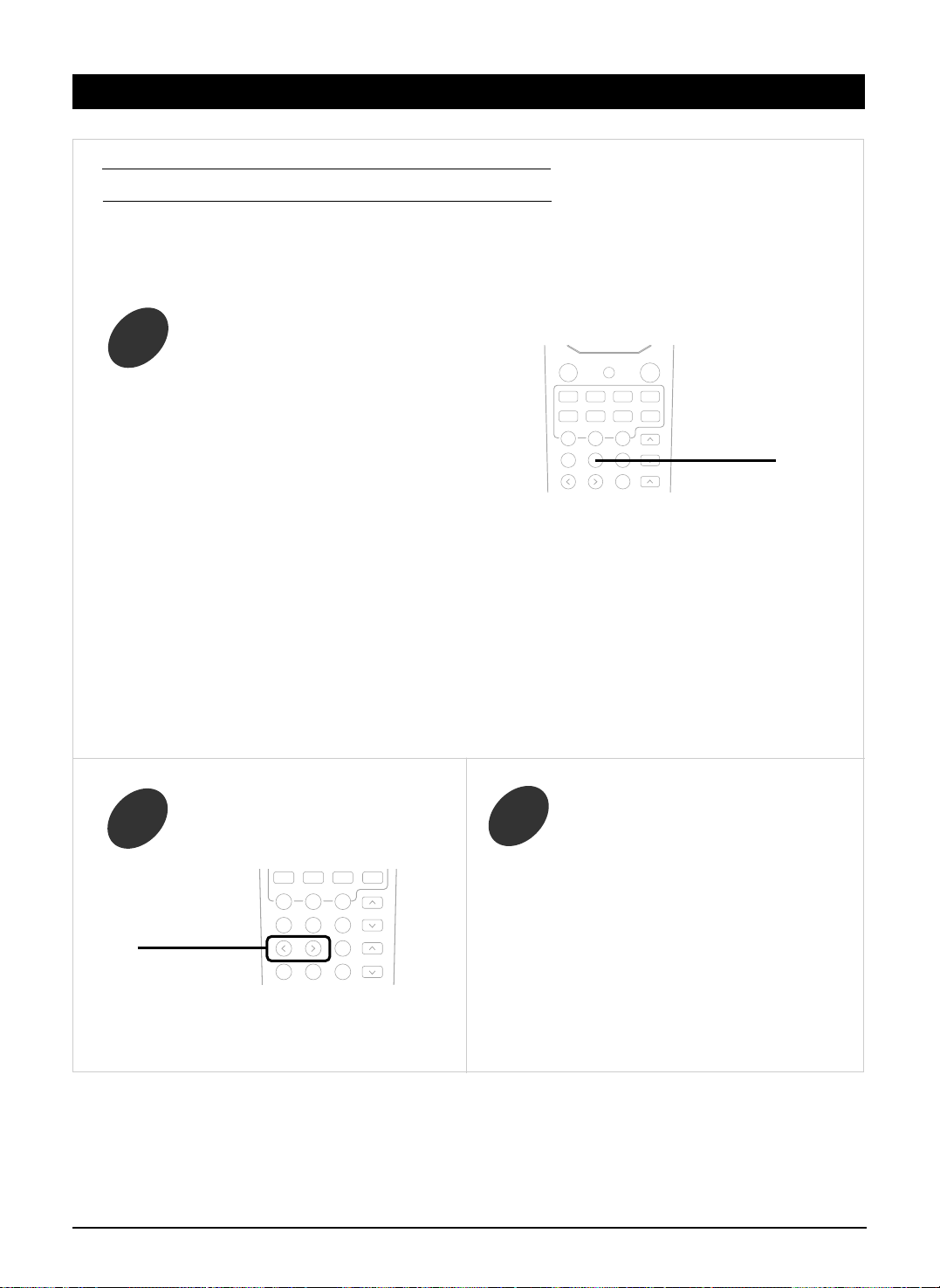
1. When selecting each setting mode
• Each time the SPEAKER SETUP button is pressed,
the speaker setting mode changes in succession and
is displayed for several seconds as follows.
• When the speaker setting mode disappears, press
the SPEAKER SETUP button repeatedly to select
the desired mode.
• When selecting the front-center-surround speaker
setting mode,
“FL - CL - SL”
• When selecting the surround back speaker setting
mode,
“SUR B - L”
• When selecting the subwoofer setting mode,
“SUB W - Y”
• Only when the surround back speaker is set to “N”,
the subwoofer type mode can be selected.
“ACTIVE”
• When the surround back speaker does not exist,
you can connect subwoofer into the terminal of
surround back speaker. In this case, the setting of
surround back speaker is N(one) and the type of
subwoofer have to be changed to PASSIVE.
2. When adjusting the selected setting
mode to the desired setting
• Each time the ADJUST UP() or DOWN()
button is pressed, one of the settings is selected and
displayed for several seconds as follows.
• You can select one of 11 different speaker settings.
FL - CL - SL / FL - CL - SN / FL - CS - SL /
FL - CN - SL / FL - CS - SN / FL - CN - SS /
FS - CS - SS / FS - CS - SN / FS - CN - SS /
FL - CS - SS / FL - CL - SS
(F: Front, C: Center, S: Surround, L: Large, S: Small, N: None)
L S N
• Depending on the surround speaker setting, you
cannot select “L” or/and “S”.
Y(es) N(o)
• When the front speaker is set to “S”, the subwoofer
is automatically set to “Y”.
ACTIVE PASSIVE
• When the surround back speaker is set to L(arge)
or S(mall), this mode set to ACTIVE automatically
and does not be displayed.
• You can adjust the distance within the range of 1 ~
30 feet in 1 foot interval.
Note:
• When the type of speaker is set to “N”, its distance
mode cannot be selected.
• When selecting the front left distance mode,
“FRONT L 10 (ft)”
SPK SET
ADJUST
UP(>), DOWN(<)
BEFORE OPERATION
Page 21

www.gateway.com
20
• When selecting the front right distance mode,
“FRONT R 10 (ft)”
• When selecting the center distance mode,
“CENTER 10 (ft)”
• When selecting the surround left distance mode,
“SURR L 10 (ft)”
• When selecting the surround right distance mode,
“SURR R 10 (ft)”
• When selecting the Dolby Virtual delay time mode,
“NARROW”
• This mode can work only in the Dolby Virtual mode.
In the other surround modes, this setting is just
displayed.
• When selecting the crossover frequency setting
mode,
“CFREQ 80”
• You can adjust the distance within the range of 1 ~
30 feet in 1 foot interval.
Note:
• When the type of speaker is set to “N”, its distance
mode cannot be selected.
NARROW : Relatively long distance for the main
listening position to front speakers.
WIDE : Relatively short distance.
80 120 160 200
TURNING THE POWER ON/OFF
In the standby mode, turn the power on.
2
Press the POWER switch.
1
• This unit enters the standby mode.
The lighting of STANDBY indicator means that the
receiver is not disconnected from the AC mains and a
small amount of current is retained to support the
memorized contents and operation readiness.
• To switch the power off, push the POWER switch
again. Then the power is cut off and the STANDBY
indicator goes off.
• Each time the POWER button on the remote control
is pressed, the receiver is turned on to enter the
operating mode or off to enter the standby mode.
• In the standby mode, if the INPUT SELECTOR
button is pressed, the receiver is turned on
automatically and the desired input is selected.
POWER
ON/ OFF
• Note : Before operating this receiver with the supplied remote control, refer to “Universal Remote Controls” on page 9 for
details about operation.
Memory backup function
• These following items, set before the receiver is turned off, are memorized:
Input settings, surround mode settings, speaker settings, channel level settings, preset stations, etc.
(unit : Hz)
POWER
※※
When the power operation switch is in the OFF or STANDBY state, the apparatus is still connected on
some AC line voltages.
Please be sure to unplug the cord when you leave home for, say, a vacation.
BEFORE OPERATION
OPERATIONS
Page 22

www.gateway.com
21
LISTENING TO A PROGRAM SOURCE
Select the desired input source.
1
• Each time the INPUT SELECTOR button on the
front panel is pressed, the input source changes as
follows;
→ TUNER → TAPE → AUX → VIDEO 1
(frequency displays.)
7-DIRECT VIDEO 3 VIDEO 2
When selecting the 7 CH DIRECT
• “7-DIRECT” is displayed and the 7 or 6 separate analog
signals from the component connected to this input can
be controlled only by volume depending on the
surround back speaker setting.
• These analog signals (except front L/R channel)
cannot be recorded.
When AUX, VIDEO 1~3 is selected as an
input source
Select the digital or analog input
connected as desired.
2
• Each time this button is pressed, the corresponding
input is selected as follows ;
A(nalog) o(ptical) 1 o(ptical) 2 c(oaxial) 1
• To listen to a DTS, Dolby Digital or MPEG program
source in the 2-CH downmix mode, in the stereo
mode, the corresponding digital input should be
selected. (For details, refer to “Downmixing into 2
front channels” on page 29.)
Notes :
• When the selected optical or coaxial digital input is
not connected, the “DIGITAL” indicator flickers,
meaning no sound.
• The sound from the component connected to the
selected digital input can be heard regardless of the
selected input source.
DIGITAL INPUT
AM/FM MODE
Depending on the input digital signal format,
select the desired decoding mode.
3
Notes :
• Only when the digital input is selected as signal input for the input sources except TUNER, TAPE and 7 CH
DIRECT, the decoding mode can be selected.
• Noise may be generated at the beginning of playback and while searching during DTS playback in the IN-AUTO
mode. In this case, try playing in the IN-DTS mode.
• Each time this button is pressed, the decoding mode
changes as follows :
IN-AUTO : The input digital signal format(DTS, Dolby
Digital, MPEG or PCM(2 channel stereo),
etc.) used by the selected digital input
source is detected automatically to perform
the necessary decoding process for optimum
surround mode.
IN-DTS : The DTS signal processing is performed only
when DTS signals are input.
IN-PCM : The PCM signal processing is performed only
when PCM signals are input.
DECODING
TUNE MODE
or
INPUT SELECTOR
7 CH DIR.
TUNER
AUX
TAPE
VIDEO1
VIDEO2
VIDEO3
or
AUTO
OPERATIONS
Page 23

www.gateway.com
22
Operate the selected component for
playback.
4
Adjust the (overall) volume.
5
• “MUTE” will flicker.
• To resume the previous sound level, press it again.
To mute the sound,
6
To listen with the headphones,
7
• The sound from the speakers is cut off.
• When listening to a DTS, Dolby Digital or MPEG
program source, if the headphones are plugged, it
enters the 2-CH downmix mode automatically. (For
details, refer to “Downmixing into 2 front
channels”on page 29.)
PHONES
• When playing back the program sources with
surround sound, refer to “ENJOYING SURROUND
SOUND” on page 23.
or
VOLUME
VOLUME
∧,∨
MUTE
OPERATIONS
Page 24

www.gateway.com
23
• You can also select the surround mode with using the buttons on the front panel.
(For details, refer to “SETTING UP THE SYSTEM ON FRONT PANEL” on page 40.)
• Each time the DSP MODE ◀ or ▶ button is pressed, the surround mode changes depending on the signal format being
input and the selected decoding mode as follows :
Signal format being input Selected decoding mode Selectable surround mode
Dolby Digital 5.1, IN-AUTO mode (DOLBY DIGITAL EX,) DOLBY DIGITAL,
Dolby Digital EX 6.1 channel sources DOLBY VIRTUAL
Dolby Digital 2-channel IN-AUTO mode (DOLBY DIGITAL EX,) PL II CINEMA, PL II
sources MUSIC, PRO LOGIC, DOLBY VIRTUAL
PCM(2 channel) sources IN-AUTO, IN-PCM mode PL II CINEMA, PL II MUSIC, PRO LOGIC,
Analog stereo sources DOLBY VIRTUAL, NEO 6 CINEMA, NEO 6
MUSIC, THEATER, MOVIE, HALL 1/2,
STADIUM, CHURCH, CLUB 1/2, ARENA 1/2,
GAME, MATRIX
DTS sources IN-AUTO, IN-DTS mode corresponding DTS mode
MPEG sources IN-AUTO mode corresponding MPEG mode
( ): possible only when surround back speaker setting is not “N”.
• When 96 kHz PCM signals are input, the stereo mode is selected automatically; the surround mode cannot be selected.
• When DTS or MPEG signals are input in the IN-AUTO or IN-DTS mode, the corresponding DTS or MPEG mode will
be selected regardless of using the DSP MODE ◀ or ▶ button.
Notes:
• When the selected decoding mode is not matched to the input signal format, the “DIGITAL” indicator flickers and
no sound is heard. Therefore, be sure to select the required decoding mode and the available surround mode
according to the input signal format.
• When the 7 CH DIRECT is selected as an input source, the decoding and surround modes cannot be selected.
• When the digital signals are not input, the desired surround mode cannot be selected.
• When the headphone is used, the surround mode cannot be selected.
To cancel the surround mode for stereo operation
• Then the stereo mode is selected.
• To cancel the stereo mode, select the desired surround mode with using the DSP MODE ◀ or ▶ button.
ENJOYING SURROUND SOUND
Selecting the surround mode
• When the AUTO OSD function is on, the corresponding setup display is on the TV screen.
DSP ◀, ▶
STEREO
OPERATIONS
Page 25

www.gateway.com
24
FL C FR SR
SW SL SB
Front Left Center Front Right Surround
Right
Subwoofer Surround Surround
Left Back
At each channel, adjust the level so that
they are all heard at the same level.
2
Cancel the test tone function.
3
• You can adjust the level of test tone for each channel so that they are all heard at the same level.
Note : When the 7 CH DIRECT is selected as an input source or the headphones are plugged, the test tone function does
not work.
• After adjusting each channel level with test tone, adjust the channel levels either according to the program sources or to
suit your tastes.
• You can also adjust the channel levels with using the buttons on the front panel.
(For details, refer to “SETTING UP THE SYSTEM ON FRONT PANEL” on page 40.)
Adjusting each channel level with test tone
Enter the test tone mode.
1
• The test tone will be heard from the speaker of each
channel for 2 seconds as follows:
FL C FR SR
SW SL SB
• When the speaker setting is “N”, the test tone of the
corresponding channel is not available.
Front Left Center Front Right Surround
Right
Subwoofer Surround Surround
Left Back
• You can select the desired channel and adjust its level
with repeating the steps 1 and 2 in “Adjusting each
channel level” procedure.
Adjusting each channel level
Select the desired channel.
1
• When it is in the stereo or Dolby Virtual mode or the speaker setting is “N”, center, surround
L/R, surround back or subwoofer channel will not be selected.
• When the headphones are plugged, only the front L/R channel can be selected.
• Each time this button is pressed, the
corresponding channel is selected and
displayed for several seconds as follows:
T.TONE
CH/LEVEL
∧,∨
T.TONE
CH.SEL
OPERATIONS
Page 26

www.gateway.com
25
Adjust the level of the selected channel
as desired.
2
Repeat the above steps 1 and 2 to adjust
each channel level.
3
Presetting and Calling the channel levels
Perform the steps 1 to 3 in “Adjusting
each channel level” on page 24~25 to
adjust each channel level you want.
1
SETUP
MEMORY
Press the SETUP button for more than 2
seconds, then it enters the setup mode.
While displaying the setup mode, press this
button short repeatedly until “P CALL” is
displayed.
2
Confirm your decision.
4
ADJUST
TUNING/PRESET
”P CALL” : When calling the preset channel
levels.
“P MEMORY” : When storing the adjusted
channel levels in the preset
memory.
While displaying “P CALL”, select “P
MEMORY” with buttons below.
3
DECODING
TUNE MODE
• The adjusted channel levels has now been stored
in the preset memory.
• When using this function with remote control unit,
press OSD button and refer to page 35~37.
• If the channel display disappears, start from the
step 1 again.
• You can store the adjusted channel levels in the memory. If you change the channel levels and want to
hear with preset levels, you can call them again.
• Select “P CALL” with performing the above steps 2 to 4.
• Then the current channel levels are changed to the preset ones.
Presetting the channel levels
Calling the channel levels
CH/LEVEL
∧,∨
OPERATIONS
Page 27

www.gateway.com
26
Adjusting the LFE level
Press the SETUP button for more than 2
seconds, then it enters the setup mode.
While displaying the setup mode, press
this button short repeatedly until “DD L”
is displayed.
1
SETUP
MEMORY
• You can adjust the LFE(Low Frequency Effect)
levels included in Dolby Digital, DTS and MPEG
program sources.
DD L DTS L MP L
While displaying “DD L”, each time the
button below is pressed, the mode changes
as follows:
2
DECODING
TUNE MODE
(Dolby Digital LFE) (DTS LFE) (MPEG LFE)
• The Dolby Digital LFE level can be adjusted within
the range of -10~0 dB and other LFE levels within
the range of -10~+10 dB.
• In general, we recommend the LFE level to be
adjusted to 0 dB.(However, the recommended LFE
level for some early DTS software is -10 dB.) If the
recommended levels seem too high, lower the setting
as necessary.
• When using this function with remote control unit,
press OSD button and refer to page 35~37.
While displaying the desired LFE mode,
adjust the level as desired.
3
ADJUST
TUNING/PRESET
• The LFE level can be adjusted and applied when Dolby Digital, DTS or MPEG program source
is inputted. In case of other program sources, this mode is adjustable, but not applied.
Press the SETUP button for more than 2
seconds, then it enters the setup mode.
While displaying the setup mode, press
this button short repeatedly until “TONE
OFF” or “BASS” is displayed.
1
BASS TRBL(treble) TONE ON
• While displaying “TONE OFF”, you cannot adjust
the tone. To adjust the tone, first perform the step 3
and change “TONE OFF” to “TONE ON”.
While displaying “BASS”, each time the
DECODING button is pressed, the tone
mode changes as follows:
2
Adjusting the tone(bass and treble)
SETUP
MEMORY
DECODING
TUNE MODE
OPERATIONS
Page 28

www.gateway.com
27
• Each adjustable range of bass and treble is -10~+10.
• In general, we recommend the bass and the treble to be set to 0(flat) level.
• At “TONE ON” mode, you can select “TONE OFF” mode and vice versa.
TONE ON: When adjusting the tone for your taste.
(“DIRECT” indicator goes off.)
TONE OFF: When listening to a program source without the tone effect.
(“DIRECT” indicator light up.)
• When using this function with remote control unit, press OSD button and refer to
page 35~37.
Notes:
• If the display of the corresponding mode disappears, start from the step 1 again.
• Extreme settings at high volume may damage your speakers.
• When the digital signals from DTS, Dolby Digital or MPEG program sources are input in available surround
mode, you cannot adjust the tone and can hear a program source without the tone effect.
While displaying the desired tone mode, adjust the tone as desired.
3
ADJUST
TUNING/PRESET
Compressing the dynamic range (Dolby Digital sources only)
• This function compresses the dynamic range of previously specified parts of the Dolby Digital sound track(with
extremely high volume) to minimize the difference in volume between the specified and non-specified parts.
This makes it easy to hear all of the sound track when watching movies at night at low levels.
• Only when the digital signals from Dolby Digital program source are input in available surround mode, the
dynamic range can be adjusted.
SETUP
MEMORY
Press the SETUP button for more than 2
seconds, then it enters the setup mode.
While displaying the setup mode, press this
button short repeatedly until “DYNR 0.0” is
displayed.
1
• Each time the ADJUST UP(▲) or DOWN(▼) button is pressed, the mode
changes as follows:
DYNR 0.0 : Off
DYNR 0.5 : Low compression
DYNR 1.0 : High compression
• When using this function with remote control unit, press OSD button and refer to
page 35~37.
ADJUST
TUNING/PRESET
While displaying “DYNR 0.0”, select the desired mode.
2
Notes:
• If the display of the dynamic range mode disappears, start from the step 1 again.
• In some Dolby Digital softwares, this function may not be available.
OPERATIONS
Page 29
www.gateway.com
28
• Each time this button is pressed, the parameter changes and is displayed for several seconds as follows;
※※
Panorama mode(“PANO”, default value: OFF)
This mode extends the front stereo image to include the surround speakers for an exciting “wraparound”
effect with side wall imaging. Select “OFF” or “ON”.
※※
Center width control(“C-WID”, default value: 0)
This adjusts the center image so it may be heard only from the center speaker, only from the left/right
speakers as a phantom image, or from all three front speakers to varying degrees.
The control can be set in 8 steps from 0 to 7.
※※
Dimension control(“DIMEN”, default value: 0)
This gradually adjusts the soundfield either towards the front or towards the rear. The control can be set
in 7 steps from -4 to +2.
• When selecting the Dolby Pro Logic II Music mode, you can adjust the various surround parameters for
optimum surround effect.
• You can also adjust the Dolby Pro Logic II Music parameters with using the buttons on the front panel.
(For details, refer to “SETTING UP THE SYSTEM ON FRONT PANEL” on page 40.)
Adjusting the Dolby Pro Logic II Music parameters
Press the PL II MUSIC PARAMETER button to select
the desired parameter.
1
PL II PARA.
• If the parameter display disappears, start from the
step 1 again.
While displaying the desired parameter,
adjust it as desired.
2
Repeat the above steps 1 and 2 to adjust
other parameters.
3
ADJUST
UP(>), DOWN(<)
OPERATIONS
Page 30

www.gateway.com
29
Downmixing into 2 front channels
• To cancel the 2 - CH downmix mode, select the
desired surround mode with the DSP MODE DOWN
(◀) or UP(▶) button.
• When the playback of the source on the player is
stopped, interrupted, etc., the 2 - CH downmix mode
is not canceled even though “ ST” and the DTS or
Dolby Digital indicators go off.
• If the headphones are plugged while the digital
signals from the DTS, Dolby Digital or MPEG
program sources are being input, it will enter the 2CH downmix mode automatically and if the
headphones are unplugged in the 2-CH downmix
mode, it will return to the previous mode.
• Allows the multi - channel DTS, Dolby Digital or
MPEG signal to be reproduced through only two
speakers or through headphones.
• When the digital signals from the DTS, Dolby Digital
or MPEG program sources are input in available
surround mode, press the STEREO button.
• “ST” indicator lights up and “2 CH DOWNMIX” is
scrolled, meaning it enters the 2-CH downmix mode,
and then the discrete multi-channels(except LFE) are
mixed down into 2 front channels.
STEREO
OPERATIONS
Page 31

www.gateway.com
30
LISTENING TO RADIO BROADCASTS
• Each time this button is pressed, the mode changes
as follows;
Tuning mode : “PRESET” goes off.
Preset mode : “PRESET” lights up.
※※
Manual tuning is useful when you already know the
frequency of the desired station.
Manual tuning
Select the tuning mode.
1
Press the below button repeatedly until the
right frequency has been reached.
2
DECODING
TUNE MODE
DECODING
TUNE MODE
or
ADJUST
TUNING/PRESET
Auto tuning
Select the tuning mode.
1
Press the below button for more than 0.5
second.
2
• Each time this button is pressed, the band is changed
as follows:
FM STEREO FM MONO AM
• When FM stereo broadcasts are poor because of weak
broadcast signals, select the FM mono mode to reduce
the noise, the FM broadcasts are reduced in monaural
sound.
To select the tuner,
To select the desired band
DIGITAL INPUT
AM/FM MODE
BAND FREQUENCY
• The tuner will now search until a station of sufficient
strength has been found. The display shows the tuned
frequency and “TUNED”.
• If the station found is not the desired one, simply
repeat this operation.
• Weak stations are skipped during auto tuning.
• When pressing the TUNE +/- buttons on the remote
control, you need not select the tuning mode on step 1.
TUNER
TUNE
-, +
TUNE
-, +
or
OPERATIONS
INPUT SELECTOR
ADJUST
TUNING/PRESET
or
Page 32

www.gateway.com
31
Repeat the above steps 1 to 3 to memorize other stations.
4
After selecting the tuner as an input
source, select the preset mode.
1
• The station has now been stored in
the memory.
• A stored frequency is erased from the
memory by storing another frequency
in its place.
• If “MEM” goes off, start again from
the above step 2.
• Then “PRESET” lights up.
• When pressing the PRESET +/- buttons on the
remote control, you need not select the preset mode
on step 1.
Tuning to preset stations
Select the desired preset number.
2
Select the desired preset number (1~30) and press the MEMORY button.
3
SETUP
MEMORY
DECODING
TUNE MODE
Presetting radio stations
• You can store up to 30 preferred stations in the
memory.
• “MEM” is flickering for 5 seconds.
Tune in the desired station with auto or
manual tuning.
1
Press the MEMORY button.
2
SETUP
MEMORY
Scanning preset stations in sequence
• The receiver will start scanning the stations in the preset
sequence and each station is received for 5 seconds.
• At the desired station, press this button again to stop
scanning.
• When pressing this button without selecting the tuner,
the tuner will be selected automatically.
or
ADJUST
TUNING/PRESET
PRESET
-, +
PRESET
-, +
P.SCAN
OPERATIONS
ADJUST
TUNING/PRESET
or
Page 33

www.gateway.com
32
ANALOG AUDIO/VIDEO RECORDING
Start recording on the TAPE.
2
Select the desired input as a recording
source except for TAPE.
1
Recording with TAPE
Select VIDEO 2 or VIDEO 3 as a recording
source.
1
Dubbing from video components onto
VIDEO 1
Select AUX as an audio recording source.
※ CD player should be connected to AUX jacks.
1
Dubbing the audio and video signals
separately onto VIDEO 1
Start play on the desired input.
3
Start recording on the VIDEO 1.
2
Start play on the VIDEO 2 or the VIDEO 3.
3
• The audio and video signals from the VIDEO 2 or the
VIDEO 3 will be dubbed onto the VIDEO 1 and you
can enjoy them on the TV set and from the speakers.
Example) When dubbing the VIDEO 2 video signal
and the CD audio signal separately onto
VIDEO 1.
• The analog signals (except front L/R channel) from the 7 CH DIRECT inputs as well as the digital signals from the coaxial or
optical digital input cannot be recorded.
• The volume and tone (bass, treble) settings have no effect on the recording signals.
INPUT SELECTOR
TUNER
AUX
VIDEO1
VIDEO2
VIDEO3
or
INPUT SELECTOR
VIDEO2
VIDEO3
or
INPUT SELECTOR
AUX
or
Press the OSD button on the remote control
unit and select FUNCTION SELECT →
VIDEO SELECT → VIDEO 2.
(Refer to page 36.)
2
OSD
OPERATIONS
Page 34

www.gateway.com
33
• The audio signal from the AUX and the video signal
from the VIDEO 2 will be dubbed and you can
enjoy them on the TV set and from the speakers.
Start recording on the VIDEO 1.
3
Start play on the AUX and the VIDEO 2
respectively.
4
DIGITAL AUDIO RECORDING WITH MD RECORDER
For digital recording, select the desired
digital input as recording signal input.
2
Select a desired input of AUX, VIDEO
1~3 as a recording source.
1
Start recording on the component
connected to OPTICAL DIGITAL OUT.
3
• Only when the OPTICAL DIGITAL OUT of this receiver is connected to the OPTICAL DIGITAL IN of the MD recorder or CD
recorder, you can enjoy high-quality sound of digital recording without converting the original signals. Refer to “CONNECTING
AUDIO COMPONENTS”/ “ CONNECTING VEDIO COMPONENTS”/“CONNECTING DIGITAL INs and OUT” on page 5~6 and
the operating instructions of the MD recorder or CD recorder.
Notes:
• Digital recording is available for the digital audio program sources such as CDs, MDs, some DVDs, etc.
• In most DVDs as well as some CDs, etc., digital recording may not be available depending on the signal format.
• There are some restrictions on recording digital signals. When making digital recordings, refer to the operating instructions of
your digital recording equipment to know what restrictions are imposed.
Start play on the desired input.
4
• Each time this button is pressed, the corresponding
input is selected as follows:
A(nalog) o(ptical) 1 o(ptical) 2 c(oaxial) 1
Note : When the selected digital input is not
connected, “DIGITAL” indicator flickers.
There will be no recording as well as no sound.
DIGITAL INPUT
AM/FM MODE
INPUT SELECTOR
AUX
VIDEO1
VIDEO2
VIDEO3
or
※ If you select AUX for hearing and VIDEO 1 for seeing, whenever you select AUX, the VIDEO 1 is selected
automatically as video input source. So you are sure to be observe the order and doing of the above steps 1
and 2.
OPERATIONS
Page 35

www.gateway.com
34
• Each time this button is pressed, the sleep time
changes and “GOOD NIGHT” message scrolls.
→ 10 → 20 → 30 → 60 → 90 → OFF
Unit : minutes
• While operating the sleep timer, “SLEEP” lights up.
Operating the sleep timer
• The sleep timer allows this unit to continue to operate
for a specified period of time before automatically
shutting off.
• To set the receiver to automatically turn off after the
specified period of time.
• Each time this button is pressed, the brightness of
fluorescent display of this unit changes as follows;
→
ON→dimmer→OFF
• In the display OFF mode, pressing any button will
restore the display ON mode.
Adjusting the brightness of the
fluorescent displays
OTHER FUNCTIONS
SLEEP
DIMMER
OPERATIONS
Page 36

www.gateway.com
35
CURRENT STATUS DISPLAY
MENU SCREEN
When the AUTO OSD mode is set to ON on the menu screen, this mode shows the status corresponding to each
operation.
• The on-screen display will automatically disappear in several seconds.
• For examples, there are 2 status displays as follows.
When selecting the desired input source When selecting the TEST TONE mode
• This function simplifies the setup procedures.
• The menu screen operation is performed easily with the CURSOR control(▲, ▼, ◀, ▶), OSD and ENTER buttons.
This unit incorporates an OSD(On-screen display) function to provide information about basic operation of this unit and to
simplify the setup procedures.
The OSD function uses a monitor TV connected to this unit as a display and has two kinds of display modes such as current
status display and menu screen.
■Notes:
• Any on-screen display shown on the monitor TV will not be recorded onto VIDEO 1.
• In some countries, this unit allows you to select either NTSC or PAL color system as video format.
If it is different from your video components and video softwares, etc., in the standby mode, press the ADJUST down(▼)
button keeping the SETUP button pressed on the front panel, then the video format is changed to the NTSC or the PAL
color system.
However, it is fixed to NTSC color system in other countries.
• The main menu will be shown.
• To turn the menu screen off, press this button again.
OSD : quit this OSD
▲, ▼ : press cursor up(▲)/ down(▼) button to move
ENTER : select menu or change the setting
• When the speaker setting is “N”, the test tone of the
corresponding channel is not shown.
• When adjusting each channel level or overall volume, the
volume level display will be shown.
• The test tone display will be shown until the test tone mode is
canceled.
Turn the menu screen on.
1
OSD
Input source Digital input
USING THE OSD
Page 37

www.gateway.com
36
Select the desired menu using the
CURSOR UP(▲) or DOWN(▼) button.
2
When selecting the SPEAKER SETUP
When selecting the FUNCTION SELECT When selecting the SURROUND MODE
Confirm your selection.
3
• Only when one of TUNER, TAPE, 7 CH DIRECT and AUX is selected, you can select a video input
source on the VIDEO SELECT menu and enjoy the audio and video signals separately.
• When dubbing them onto VIDEO 1, select either VIDEO 2 or VIDEO 3 on the VIDEO SELECT menu.
• The displayed surround mode changes depending on the input signal format.(Refer to “Selecting the
surround mode” page 23.)
CURSOR
▲,▼
ENTER
USING THE OSD
Page 38

www.gateway.com
37
Select the desired menu or(and) change the
condition with the corresponding buttons.
4
Repeat the above steps 2~4 to change the
conditions on other menus.
5
When selecting the AUTO OSD
• Each time the ENTER button is pressed, the AUTO OSD mode is set to ON to turn on the current display or OFF
to turn it off.
• When the AUTO OSD mode is set to ON, the current status display overlays the program image on the monitor TV
and may interference with your movie enjoyment. In such a case, set it to OFF.
Notes:
• OSD function on this unit can display all the settings.
• According to your selections for the input source, input signal, decoding mode, surround mode, speaker settings,
etc., the conditions of each menu may differ.
• When adjusting the speaker distance or channel level, etc., use the CURSOR LEFT(◀) and RIGHT(▶) buttons.
• In OSD, the parenthesized passage means that it is changeable by pressing CURSOR LEFT(◀) and RIGHT(▶)
buttons.
When selecting the CH LEVEL SETUP
• You can adjust the preset channel level in PRESET TRIM menu.
The adjusted is(are) memorized in preset channel level.
• You can adjust the current channel level in CH LEVEL SETUP mode.
The adjusted is(are) just memorized, not in preset channel level.
• If you press ENTER button on the remote control unit after adjusting the current channel level in CH LEVEL
SETUP menu, that setting is memorized in preset channel level. You can load it again by selecting PRESET CALL.
When selecting
PRESET TRIM menu
When selecting
CH LEVEL TRIM menu
USING THE OSD
Page 39

www.gateway.com
38
PROBLEM POSSIBLE CAUSE REMEDY
No power
No sound
No sound from the surround
speakers
No sound from the center
speaker
No sound from the surround
back speaker
Stations cannot be received
Preset stations cannot be
received
Poor FM reception
Continuous hissing noise during
FM reception, especially when a
stereo broadcast is received.
Continuous or intermittent
hissing noise during AM
reception, especially at night.
Remote control unit does not
operate.
OSD function is not available
• The AC input cord is disconnected.
• Poor connection at AC wall outlet or the outlet
is inactive.
• The speaker cords are disconnected.
• The master volume is adjusted too low.
• The MUTE button on the remote control is
pressed to ON.
• Incorrect selection of the input source.
• Incorrect connections between the
components.
• Surround mode is switched off(stereo mode).
• Master volume and surround level are too low.
• A monaural source is used.
• Surround speaker setting is “N”.
• Dolby Virtual, stereo mode, etc. is selected.
• Center speaker setting is “N”.
• Master volume and center level are too low.
• The input signal format or the current surround
mode cannot support the 6.1 surround playback.
• Master volume and surround back level are
too low.
• Surround back speaker setting is “N”.
• No antenna is connected.
• The desired station frequency is not tuned in.
• The antenna is in wrong position.
• An incorrect station frequency has been
memorized.
• The memorized stations are cleared.
• No antenna is connected.
• The antenna is not positioned for the best
reception.
• Weak signals.
• Noise is caused by motors, fluorescent lamps
or lightning, etc.
• Batteries are not loaded or exhausted.
• The remote sensor is obstructed.
• Video connections between this unit and the
TV monitor are not made correctly.
• Connect the cord securely.
• Check the outlet using a lamp or another
appliance.
• Check the speaker connections.
• Adjust the master volume.
• Press the MUTE button to cancel the muting
effect.
• Select the desired input source correctly.
• Make connections correctly.
• Select a surround mode.
• Adjust master volume and surround level.
• Select a stereo or surround source.
• Select the desired surround speaker setting.
• Select the desired surround.
• Select the desired center speaker setting.
• Adjust master volume and center level.
• Under the proper situations, perform the 6.1
surround playback.
• Adjust master volume and surround back
level.
• Select the desired surround back speaker
setting.
• Connect an antenna.
• Tune in the desired station frequency.
• Move the antenna and retry tuning.
• Memorize the correct station frequency.
• Memorize the stations again.
• Connect an antenna.
• Change the position of the antenna.
•
Change the position of the antenna.
•
Install an outdoor antenna.
• Keep the receiver away from noise sources.
• Install an outdoor AM antenna.
• Replace the batteries.
• Remove the obstacle.
• Make proper video connections.
If a fault occurs, run through the table below before taking your receiver for repair.
If the fault persists, attempt to solve it by switching the receiver off and on again. If this fails to resolve the situation, consult
your dealer. Under no circumstances should you attempt to repair the receiver yourself. This could void the warranty.
TROUBLESHOOTING GUIDE
Page 40

www.gateway.com
39
Amplifier Section
Power output, stereo mode, 6 Ω, THD 0.3 %, 40 Hz~20 kHz | 2××100 W
Total harmonic distortion, 6 Ω, 50 W, 1 kHz | 0.09%
Intermodulation distortion
60 Hz : 7 kHz= 4 : 1 SMPTE, 6 Ω, 100 W | 0.1%
Input sensitivity, 47 kΩ
Line (AUX) | 200 mV
Signal to noise ratio, IHF “A” weighted
Line (TAPE) | 95 dB
Frequency response
Line (AUX, TAPE), 20 Hz~44 kHz | ±±3 dB
Output level
TAPE OUT, 2.2 kΩ | 180 mV
Bass/Treble control, 100 Hz/10 kHz | ±±10 dB
Surround mode, only channel driven
Front power output, 6 Ω, 1 kHz, THD 0.3 % | 100 W+100 W
Center power output, 6 Ω, 1 kHz, THD 0.3 % | 100 W
Surround power output, 6 Ω, 1 kHz, THD 0.3 % | 100 W+100 W
Surround back power output, 6 Ω, 1 kHz, THD 0.3 % | 100 W
Digital Audio Section
Sampling frequency | 32, 44.1, 48, 96 kHz
Digital input level
Coaxial, 75 Ω | 0.5 Vp-p
Optical, 660 nm | -15 ~ -21 dBm
Video Section
Video format | NTSC
Input sensitivity(=Output level), 75 Ω
Video (Composite(normal)) | 1 Vp-p
S-Video (luminance signal) | 1 Vp-p
(chrominance signal) | 0.286 Vp-p
FM Tuner Section
Tuning frequency range | 87.5~108 MHz
Usable sensitivity, THD 3%, S/N 30 dB | 17.2 dBf
50 dB quieting sensitivity, mono/stereo | 20.8/41.2 dBf
Signal to noise ratio, 1 mV, mono/stereo | 72/65 dB
Total harmonic distortion, 1 kHz, mono/stereo | 0.2/0.4 %
Frequency response, 20 Hz~15 kHz | ±±1 dB
Stereo separation, 65 dBf, 1 kHz | 45 dB
Capture ratio | 4 dB
IF rejection ratio | 120 dB
AM Tuner Section
Tuning frequency range | 520~1710 kHz
Usable sensitivity | 500 μμV/m
Signal to noise ratio | 40 dB
Selectivity | 25 dB
General
Power supply | 120 V~60 Hz
Power consumption | 110 W
Dimensions (W×H×D) | 17-1/8××2-7/8××10 inches (435××73.5××254 mm)
Weight (Net) | 4.2 kg (9.3 Ibs)
Note: Design and specifications are subject to change without notice for improvements.
SPECIFICATIONS
Page 41

www.gateway.com
40
SETTING UP THE SYSTEM ON FRONT PANEL
• You can adjust the system settings in succession according to your system using the buttons on the front panel.
• This section explains how to adjust the settings using the buttons on the front panel.
• Refer to the corresponding pages indicated in ( ) for details about each mode and use of remote control.
Press the SETUP button for more than 2 seconds, then it enters the setup mode.
While displaying the setup mode, each time the SETUP button is pressed, the setup mode changes as
follows:
1
While displaying the selected setup mode, each time the DECODING button is pressed, the setting mode changes
as follows:
2
While displaying the selected setting mode, each time the ADJUST UP(▲) or DOWN(▼) button is pressed, the
mode is adjusted to the desired setting.
Notes:
• Only when selecting preset channel levels, press ADJUST UP(▲) or DOWN(▼) button to change the setting
mode and DECODING button to confirm your decision(refer to page 25).
• If the display of the corresponding mode disappears, start from the step 1 again.
• To help your understanding, each setting operation is explained with using its default setting.
3
INITIALIZING THE SYSTEM
• When the display is not normal or when the operation of the unit does not shows the reasonable result, the
initialization of this unit is required by the following procedure.
After seeing the flickering standby
indicator, take your hand(s) off from
buttons.
In standby mode, press SETUP and
DECODING buttons at the same time.
SETUP
MEMORY
DECODING
TUNE MODE
1
2
• If this unit has been reset, all the button settings
are reset to the default values (the values set upon
shipment from the factory).
APPENDIX
Page 42

www.gateway.com
41
Turn back to previous surrond mode and
select the desired surround mode.
(For details, refer to “Selecting the surround
mode” on page 23.)
Adjust the selected mode as desired.
(For details, refer to “Adjusting the speaker
settings” on page 18.)
Adjust the level of the selected channel as
desired.
(For details, refer to “Adjusting each
channel level” on page 24.)
Adjust the tone as desired.
(For details, refer to “Adjusting the tone
(bass and treble)” on page 25.)
Adjust the level of the selected LFE channel
as desired.
(For details, refer to “Adjusting the LFE
channel level” on page 26.)
[2] Select Preset Call or Preset Memory as
desired.
Adjust the selected parameter as desired.
(For details, refer to “Adjusting the Dolby
Pro Logic II Music parameters” on page 28.)
STEREO(or 2 CH DOWNMIX) mode
( ): Possible when the digital signals from the DTS
or Dolby Digital program sources are being
input.
FL-CL-SL SUR B - L SUB W-Y FRONT 10(ft)
CFREQ80 NARROW SURROUND 10(ft) CENTER 10(ft)
FL C FR SR SB
SW SL
BASS TRBL TONE ON
• While displaying “TONE OFF”, you cannot
adjust the tone.
DD L DTS L MP L
[3] Confirm your decision.
PANO OFF C-WID 0 DIMEN 0
[ 1 ] [ 2 ] [ 3 ]
SETUP
MEMORY
DECODING
TUNE MODE
ADJUST
TUNING/PRESET
Surround mode
: not available when the
input signal is 96kHz PCM
or headphone is used.
Speaker setup mode
(“FL - CL - SL”)
Channel level trim mode
(“FL 0”)
Tone mode
(“BASS” or “TONE OFF”)
: available only when STEREO is
selected during that analog or
PCM signal is input.
LFE channel level mode
(“DD L”)
Dolby Pro Logic II Music
Parameter mode
(“PANO OFF”)
: available only when the current
surroudn mode is Dolby Pro Logic II
Music.
[1]
Preset channel level mode
(“P CALL”)
Dynamic range mode
(“DYNR 0.0”)
: available only when the input
signal is Dolby Digital.
Select the desired setting.
(For details, refer to “compressing the
dynamic range(Dolby Digital sources only)”
on page 27.)
Ignore this step and skip to the step 3.
APPENDIX
Page 43

www.gateway.com
42
AOC 005 003
Admiral 041 031
Aiko 014
Akai 005
Alaron 026
Ambassador 024
America Action 027
Ampro 043
Anam 027 047 048 049
Audiovox 030 027 014 034
Baysonic 027
Belcor 003
Bell & Howell 019 001
Bradford 027
Brockwood 003
Broksonic 028 031
CXC 027
Candle 005 011
Carnivale 005
Carver 010
Celebrity 050
Cineral 030 014
Citizen 012 005 011 006 014
Concerto 011
Contec 027
Craig 027
Crosley 010
Crown 027 006
Curtis Mathes 007 010 019 008 030 041
012 005 016 011 001 006
022 032 038 040
Daewoo 030 003 006 014 034 035
Daytron 003
Denon 016
Dumont 002 003
Dwin 044 036
Electroband 050
Emerson 019 028 031 027 029 025
003 026 006 024 034 035
Envision 005
Fisher 019
Fujitsu 026
Funai 027 026 023
Futuretech 027
GE 007 008 030 041 029 025
004 015 038 040
Gibralter 002 005 003
TV
Goldstar 005 025 003 011
Gradiente 009 011
Grunpy 027 026
Hallmark 025
Harley Davidson 026
Harman/Kardon 010
Havard 027
Hitachi 016 011 018
Infinity 010
Inteq 002
JBL 010
JCB 050
JVC 009 046
KEC 027
KTV 027 005 006
Kenwood 005 003
LG 011 003
LXI 007 010 019 020 025
Logik 001
Luxman 011
MGA 017 005 025 003
MTC 012 005 003 011
Magnavox 010 005 026
Magestic 001
Marantz 010 005
Matsushita 042
Magatron 025 016
Memorex 019 042 031 017 025 011
001
Midland 007 002 008 006 015
Minutz 004
Mitsubishi 041 017 025 003
Motorola 041
Multitech 027
NAD 020 025 022
NEC 005 003 011
NTC 014
Nikko 005 025 014
Onwa 027
Optimus 019 042 022
Optonica 041 021
Orion 028 031 026
Panasonic 008 042
Penney 007 020 008 012 005 025
004 003 011 006 015 040
Pilco 010 031 005 016 003
Philips 010
SETUP CODE TABLE
APPENDIX
Page 44

www.gateway.com
43
Admiral 027 021
Adventura 000
Aiko 025
Aiwa 005 000
Akai 026
America Action 025
America High 004
Asha 023
Audiovox 005
Beaumark 023
Bell & Howell 017
Brocksonic 021
Broksonic 020 018 021 001
CCE 015 025
Calix 005
Canon 004
Carver 081
Cineral 025
Citizen 005 025
Colt 015
Craig 005 012 023 015 024
Curtis Mathes 013 004 026 028
Cybernex 023
Daewoo 010 025
Denon 008
Dynatech 000
Electrohome 005
Electrophonic 005
Emerex 002
Emerson 005 020 000 018 009 021
001 025
Fisher 012 017
Fuji 004 003
Funai 000
GE 013 004 027 023
Garrard 000
Go Video 052
GoldStar 005 006
Gradiente 000
HI-Q 012
Harley Davidson 000
Harman/Kardon 016 006
Harwood 015
VCR
Pilot 005 003 006
Pioneer 022
Portland 003 006 014
Prism 008
Proscan 007
Proton 025 032
Pulsar 002 003
Quasar 008 042 021
RCA 007 008 041 003 013 015
037 038 039 040
Radio Shack 007 019 021 027 005 025
003 011 006
Realistic 019 021 027 005 025 003
011 006
Runco 002 005 033
SSS 027 003
Sampo 005 006
Samsung 012 005 025 003 011 045
Samsux 006
Sansei 030
Sansui 031
Sanyo 019
Scimitsu 003
Scotch 025
Scott 028 027 025 003 026
Sears 007 010 019 020 025 026
011 006
Semivox 027
Semp 020
Sharp 041 021 006
Sherwood 000
Shogun 003
Signature 001
Sony 050
Soundesign 027 025 026
Squareview 023
Starlite 027
Supreme 050
Sylvania 010 005
Symphonic 023
TMK 025 011 024
Tandy 041
Technics 008 042
Technoi Ace 026
Techwood 008 011
Teknika 010 027 017 012 003 026
011 001 006 014
Telefunken 011
Toshiba 019 020 012
Totevision 006
Vector Research 005
Victor 009
Vidikron 010
Vidtech 025 003
Wards 010 021 005 025 004 003
026 011 001
White Westinghouse
031 034 035
Yamaha 005 003
Zenith 002 031 001 014
APPENDIX
Page 45

www.gateway.com
44
Headquarter 011
Hitachi 000 008 026
Hughes Net.Sys 008
JVC 014 026
Jensen 026
KEC 005 025
KLH 015
Kenwood 014 026 006
Kodak 004 005
LXI 005
Lloyd’s 000
Logik 015
MEI 004
MGA 023 009
MGN Technology 023
MTC 023 000
Magnasonic 025
Magnavox 004 007 016 000 019
Magnin 023
Marantz 004 016
Marta 005
Matsushita 004 028 029
Memorex 004 005 027 007 012 023
000 017 021 011 031 032
Minolta 008
Mitsubishi 027 014 009
Motorola 004 027
Multitech 000 015
NEC 017 014 026 006
Nikko 005
Noblex 023
Olympus 004
Opimus 005 027 017 028 029 030
031 032
Orion 020 021 001
Panasonic 004 028 022 029 031
Penny 004 005 023 008 006
Pentax 008
Philco 004 021
Philips 004 016
Pilot 005
Pioneer 014
Profitronic 023
Proscan 013
Protec 015
Pulsar 007
Quarter 011
Quartz 011
Quasar 004 028 029 031
RCA 013 004 027 023 008 019
Radio Shack 000
Radix 005
Randex 005
Realistic 004 005 027 012 000 017
011
Runco 007
STS 008
Samsung 023 010 033
Sanky 027 007
Sansui 000 014 021 026 024
Sanyo 012 023 017 011
Scott 020 010 018 009
Sears 004 005 012 000 008 017
011
Semp 010
Sharp 027
Shintom 015
Shogun 023
Singer 015
Sony 004 002 000 003
Syvania 004 016 000 009
Symphonic 000
TMK 023
Tatung 026
Teac 000 026
Technics 004 028
Teknika 004 005 000
Thomas 000
Toshiba 010 009
Totevision 005 023
Unitech 023
Vector 010
Vector Research 006
Video Concepts 010
Videosonic 023
Wards 013 004 027 012 016 023
000 008 015 019
White WestingHouse
021 025
XR-100 004 000 015
Yamaha 006
Zenith 007 000 021 003
Ameira High 004 (TV use 008)
Brocksonic 001
Colt 015
Cutis Mathes 004 (TV use 008)
Daewoo 025
Emerson 001
Funai 000
GE 004 (TV use 008) 013 (TV use 012)
027 (TV use 041) 023
Hitachi 004 (TV use 008) 000
HQ 000
Lloyds 000
MGA 023
Megavox 016 (TV use 010) 004 (TV use 008)
000
APPENDIX
Page 46

www.gateway.com
45
Magnin 023
Memorex 005 028 (TV use 025)
Mitsubishi 027 (TV use 041)
Orion 001
Panasonic 004 (TV use 008) 028 (TV use 042)
Penney 004 (TV use 008) 023
028 (TV use 042)
Quasar 004 (TV use 008) 028 (TV use 042)
RCA 013 (TV use 012) 004 (TV use 008)
027 (TV use 041)
Sansui 000
Sanyo 023
Sear 000 005
Sharp 027 (TV use 041)
Sony 002 (TV use 000)
Symphonic 000
Zenith 000
Harman/Kardon 009
JVC 008
Kenwood 005
Megavox 011
Mitsubishi 016
Onkyo 011
Panasonic 013
Philips 011 006
Pioneer 003 014 026
Proscan 002
RCA 002
Samsung 017
Sherwood 001 012 000 018 019
020 021 022 023 025
Sony 004
Technics 013
Theta Digital 014
Toshiba 011
Yamaha 013 007
Zenith 011 010
ABC 002 003 009 030
007 006 008
Allegro 018 021
Archer 018 026
Bell&Howell 009
Century 018
Citizen 018 021
Comtronics 014
Contec 011
Easten 001
Emerson 026
Everquest 010 014
Focus 022
Garrard 018
Gemini 010
General Instrument
033 276 006 034
GoldStar 017 040
Goodmind 026
Hamlin 012 020 004 013
Hitachi 006
Hytex 007
Jasco 010 018 021
Jerrold 002 007 033 032 009 010
006 034
Memolex 000
Movie Time 015
NSC 015
Oak 011
Optimus 031
Panasonic 000 016 031
Paragon 000
Philips 018
Pioneer 017 025
Popular Mechanics 022
Pulsar 000
Quasar 000
RCA 031
Radio Shack 010 021 026 028
Recoton 022
Regal 012 020
Regency 001
Rembrandt 006
Runco 000
SL Marx 014
Smasung 017 014
Scientific Atlanta 003 023 030 027
Signal 010 014
Signature 006
Sprucer 031
Starcom 002 010
DVD
CBL
APPENDIX
Page 47

www.gateway.com
46
Stargate 010 014 026
Starquest 010
TV86 015
Teleview 014
Tocom 007 008
Toshiba 000
Tusa 010
Unika 018
United Artists 007
Universal 153 019
Viewstar 015
Zenith 000 024
Zentek 022
AlphaStar 008
Chaparral 001
Echostar 009
Expreevu 009
General Instrument
016 015 018
HTS 009
Hitachi 011
Hughes Net.Sys 007
JVC 009
Jerrold 016 015
Megavox 006 005
Memorex 006
Next Level 006
Panasonic 017
Philips 006 005
Primestar 016 015
RCA 003 000 002 012
Radio Shack 018
Realistic 014
Sony 004
Star Choice 018
Toshiba 010
Uniden 006 005 014
Zenith 013
Denon 007
Mitsubishi 007
NAD 007
Pioneer 007
Sony 017 018
SAT
AUX-LD
Aiwa 004 034
Carver 004
Harman/Kardon 016 004
JVC 022 024
Kenwood 008
Megavox 004
Marantz 004
Onkyo 012 025
Opimus 002 020
Panasonic 038
Pioneer 002 020 011
Sansui 004
Sony 021 014 026
Technics 038
Victor 024
Wards 002
Yamaha 010 009
AUX-TAPE
Awia 029
Carver 023
Curtis Mathes 027
Denon 037
Harman/Kardon 040
Linn 023
Megavox 023
Marantz 023
Panasonic 039
Philips 023 040
Pioneer 003 027
Sony 019 033
Technics 039
Wards 003
Yamaha 028
AUX-AMP
Sherwood 000 (for tape deck)
035 (for MD recorder)
AUX-TAPE/MD
APPENDIX
Page 48

www.gateway.com
47
GE 043
Lutron 044
One For All 042
Radio Shack 043
Security System 042
Universal X10 042
X10 042
Awia 045 059 029
Fisher 005
Harman/Kardon 046
JBL 046
JVC 047
Jerrold 031
RCA 006
Scientific Artlanta 032
Sony 045
Starcom 031
AUX-DBS
Archer 013
GC Electronics 013
Jebsee 013
Rabbit 036
Radio Shack 013
AUX-ACCESSARY
AUX-HOME AUTOMATION
Awia 010 030
Burmester 019
California Audio Lab
002
Carver 010 012 020
DKK 001
Denon 028 034
Emerson 035
Fisher 012 033
Garrard 019 018
Genexxa 004 035
Harman/Kardon 010 011
Hitachi 004
JVC 007
CD
Kenwood 003 029 016 024 025
Krell 010
LXI 035
Linn 010
MCS 002
MTC 019
Megavox 010 035
Marantz 002 010 013
Mission 010
NSM 010
Nikko 033
Onkyo 008 026
Opimus 001 004 012 035 029
019 009 021 020
Panasonic 002 031
Parasound 019
Philips 010 023
Pioneer 004 035 021 017
Proton 010
QED 010
Quasar 002
RCA 012 035 006 036
Realistic 012 019 013
Rotel 010 019
SAE 010
Sansui 010 035
Sanyo 012
Scott 035
Sears 035
Sharp 029 013 037
Sherwood 013 027 038 039 040 041
000
Sony 001 014 022
Soundesign 009
Tascam 019
Teac 019 018 033 013
Technics 002 031
Victor 007
Wards 010 006
Yamaha 005 015
Yorx 032
APPENDIX
Page 49

www.gateway.com
48
GATEWAY CONSUMER ELECTRONICS
PRODUCTS SERVICES BOOKLET
Extended Service Plan
Accidental Damage Protection Plan
Standard Terms of Sale and Limited
Warranty Agreement
WARRANTY BOOKLET
Page 50

www.gateway.com
49
This booklet includes Gateway’s service plans and Standard Terms of Sale and
Limited Warranty Agreement for consumer electronics products. The service plans
you purchased are listed on your invoice.
Please carefully read the plans for the services you purchased, as well as the
Standard Terms of Sale and Limited Warranty Agreement.
Extended Service Plan Page 50
Accidental Damage Protection Plan Page 53
Standard Terms of Sale
and Limited Warranty Agreement Page 56
© Copyright 2002-2003
Gateway, Inc. Gateway, the Spotted G Gateway Logo, the Spotted G Logo, the Black-and-White
Spot Design, Gateway Extended Service and Gateway Accidental Damage Protection are trademarks or registered
trademarks of Gateway, Inc. in the U.S. and other countries.
WARRANTY BOOKLET
Page 51

www.gateway.com
50
WARRANTY BOOKLET
Gateway Extended Service Plan
SM
Consumer Electronics Products
This Gateway Extended ServiceSMplan (“Plan”) extends the term of the limited warranty coverage for Gateway
®
branded consumer electronics products. The product covered by this Plan and the term of this Plan are described in
your invoice and your invoice is incorporated as part of this Plan.
Limited Warranty:
• The term of the limited warranty begins when your Gateway product is shipped to you and lasts for the period stated
on your invoice. Please refer to Gateway Standard Terms of Sale and Limited Warranty Agreement for the scope and
terms of your limited warranty.
• Big Screen (42” or larger) display products: Gateway will provide in-home repair service or deliver a replacement
product to you in exchange for your original product at its cost, including the cost of shipping. If the term of your Plan
exceeds 1 year, Gateway will try to provide in-home service within 3 business days. In-home service is only available
in the continental US. If Gateway is unable to provide in-home repair or replacement services, it will perform any
necessary repairs to your product at an authorized repair facility. Gateway will pay all costs, including shipping costs,
to repair or replace defective products (including remote control devices).
Customer Requirements:
• You must contact Gateway to obtain service under this Plan.
• You must assist Gateway in diagnosing issues with your Gateway product and follow Gateway warranty processes. If
Gateway determines your product requires service, you must deliver it to a Gateway service facility. You are
responsible for properly packaging your product, paying all shipping costs, loss or damage to the product during
shipping, and any other taxes, fees or charges associated with transporting the product to a Gateway service facility.
Gateway will pay the costs of returning the product to you from the service facility. If your Plan includes in-home
service, Gateway may, at its discretion, dispatch a service representative to repair or replace the product.
Replacement parts and products will be new or serviceably used, comparable in function and performance to the
original part.
• You are responsible for properly maintaining your product and protecting it from damage.
• You must obtain service from Gateway under this Plan. Gateway will not reimburse you for service performed by others.
Limitations:
• This Plan does not cover damages caused by your failure to follow all instructions contained in the product user
guide, accident, misuse or abuse, or unauthorized parts or service.
• This Plan does not cover consumables, such as batteries and fuses, or the results of normal usage, such as gradual
image degradation, uneven screen aging, burned-in images and pixel failure within designed specifications or that do
not materially alter the product functionality.
• This Plan does not cover defects to the product that you knew about before you purchased this Plan (a pre-existing
condition).
• You may not assign or transfer this Plan. This Plan terminates when you transfer or dispose of your Gateway product.
You may not renew or extend this Plan.
• You may cancel this Plan for any reason at any time. To cancel, you must send written notice to: Gateway Service
Contract Cancellation, Customer Service Department, 610 Gateway Drive, North Sioux City, SD 57049. Unless
otherwise specified under applicable law, if you cancel within 30 days after you received this Plan, Gateway will issue
a full refund of the Plan purchase price less the cost of parts/services provided during the first 30 days (the “30-Day
Refund”). If Gateway fails to pay you the 30-Day Refund within 45 days of your cancellation of this Plan and the Plan
is deemed void under applicable law, you may also be entitled to a monthly penalty equal to 10% of the Plan
purchase price in addition to the 30-Day Refund. If you cancel after 30 days, Gateway will refund a pro rata portion of
the Plan purchase price based on the time expired (measured on a weekly basis) less a cancellation charge of $25 or
10% of the Plan purchase price (whichever is less), and less the cost of any parts/services actually provided to you
prior to cancellation. Gateway cannot cancel this Plan except for fraud, material misrepresentation or non-payment by
you; or if required to do so by a regulatory authority. If Gateway cancels this Plan, Gateway will give you 30 days
advance notice and refund a pro rata portion of the purchase price based on the time expired (measured on a weekly
basis) less the cost of any parts/services actually provided to you prior to cancellation.
• This Plan is not available in all jurisdictions. Please refer to your invoice to determine whether this Plan applies to you.
• If you request service outside the United States, the level of service available to you may vary. In particular, you may
be required to pay shipping costs to and from Gateway to obtain service. Please refer to Gateway’s Standard Terms
of Sale and Limited Warranty Agreement for more information.
Page 52

www.gateway.com
51
WARRANTY BOOKLET
Financial Assurance:
Unless otherwise required by applicable law, this Plan is not insured under any reimbursement insurance policy.
Gateway Country Stores LLC, 610 Gateway Drive, North Sioux City, South Dakota 57049, is the administrator and
obligor of this Plan in all jurisdictions except Wisconsin, in which Gateway, Inc., 610 Gateway Drive, North Sioux City,
South Dakota 57049, is the administrator and obligor of this Plan. Obligations of Gateway Country Stores LLC under this
Plan are backed by the full faith and credit of Gateway, Inc.
GATEWAY WILL PROVIDE THE SERVICES ON THE TERMS DESCRIBED ABOVE AND THE TERMS IN
GATEWAY’S STANDARD TERMS OF SALE AND LIMITED WARRANTY AGREEMENT (WHICH IS SET FORTH ON
PAGE 11 OF THIS BOOKLET, AND ALSO AVAILABLE AT HTTP://WWW.GATEWAY.COM/
), WHICH TOGETHER ARE
THE COMPLETE AGREEMENT BETWEEN YOU AND GATEWAY FOR THE SERVICES YOU HAVE PURCHASED.
UNLESS THIS PLAN SPECIFIES OTHERWISE OR PROVIDES TERMS INCONSISTENT WITH GATEWAY
STANDARD TERMS OF SALE AND LIMITED WARRANTY AGREEMENT, ALL THE TERMS OF GATEWAY
STANDARD TERMS OF SALE AND LIMITED WARRANTY AGREEMENT ARE INCORPORATED INTO THIS PLAN BY
REFERENCE.
Special State Laws
FOR RESIDENTS OF CONNECTICUT ONLY:
You should note that under Regulations of Connecticut State Agencies §42-260-3, Gateway and you are required to
make reasonable efforts to resolve disputes regarding this Plan. If Gateway and you cannot reach an agreement, your
may file a written complaint with the State of Connecticut Insurance Department, P.O. Box 816, Hartford, CT 061420816, Attn: Consumer Affairs.
FOR RESIDENTS OF FLORIDA ONLY:
• GATEWAY, INC. D/B/A GATEWAY COMPUTERS, INC. IS THE ADMINISTRATOR AND OBLIGOR OF THIS
PLAN.
• GATEWAY, INC. D/B/A GATEWAY COMPUTERS, INC. has retained Gateway Country Stores, LLC located at 610
Gateway Drive, North Sioux City, South Dakota 57049 as its sales representative in Florida.
• If GATEWAY, INC. D/B/A GATEWAY COMPUTERS, INC. cancels within 30 days after you received this Plan,
GATEWAY, INC. D/B/A GATEWAY COMPUTERS, INC. will issue a full refund of the Plan purchase price. If
GATEWAY, INC. D/B/A GATEWAY COMPUTERS, INC. cancels this Plan any time after 30 days, GATEWAY, INC.
D/B/A GATEWAY COMPUTERS, INC. will refund a pro rata portion of the purchase price based on the time expired
(measured on a weekly basis).
FOR RESIDENTS OF NEVADA ONLY:
You may cancel this Plan at any time and for any reason. If you cancel within 30 days after you received this Plan and
you have not
filed a claim, the Plan is void and Gateway will issue a full refund of the Plan purchase price. If you cancel
this Plan at any time after 30 days or you cancel this Plan within 30 days and have filed a claim, Gateway will refund a
pro rata portion of the Plan purchase price based on the time expired (measured on a weekly basis) less a cancellation
charge of $25 or 10% of the Plan purchase price (whichever is less). If Gateway cancels within 30 days after you
received this Plan, Gateway will issue a full refund of the Plan purchase price. If Gateway cancels this Plan any time
after 30 days, Gateway will refund a pro rata portion of the purchase price based on the time expired (measured on a
weekly basis).
FOR RESIDENTS OF PUERTO RICO ONLY:
• You will not be liable for any sums for services under this Plan, other than costs, fees and other payments specified
under this Plan.
• You may cancel this Plan for any reason at any time. To cancel, you must send written notice to: Service Contract
Cancellation, Customer Service Department, Gateway Companies, Inc., 610 Gateway Drive, North Sioux City, SD
57049. If you cancel this Plan, Gateway may be liable to refund you the unearned portion of the Plan purchase price,
on a pro rata basis, with no
discount whatsoever.
• Gateway will not cancel this Plan except for non-payment by you or if you commit a direct violation of this Plan, if and
to the extent that this Plan specifies that such violation justifies cancellation. If Gateway cancels this Plan, Gateway
will give you 30 days advance notice and may be liable to refund you the unearned portion of the Plan purchase price,
on a pro rata basis, with no discount whatsoever.
Page 53

www.gateway.com
52
WARRANTY BOOKLET
FOR RESIDENTS OF SOUTH CAROLINA ONLY:
Gateway is subject to S.C. Stat. ㄴ38-78-50, and this Plan reflects all of the requirements specified by this statutory
provision. If the Gateway does not timely resolve your claims under this Plan within sixty (60) days of proof of loss, you
may contact the South Carolina Department of Insurance, Post Office Box 100105, Columbia, SC 29202-3105, or (800)
768-3467.
FOR RESIDENTS OF TEXAS ONLY:
If you have any consumer complaints regarding this Plan, you should contact the Texas Department of Licensing and
Regulation, P.O. Box 12157, Austin, TX 78711, (512) 463-6599 or (800) 803-9202 (in Texas).
FOR RESIDENTS OF WASHINGTON ONLY:
You and Gateway hereby submit to the non-exclusive jurisdiction of any state or federal court sitting in the State of
Washington in any civil action arising out of or relating to this Plan or the transactions contemplated herein.
FOR RESIDENTS OF WISCONSIN ONLY:
THIS PLAN IS SUBJECT TO LIMITED REGULATION BY THE OFFICE OF THE WISCONSIN COMMISSIONER OF
INSURANCE.
FOR RESIDENTS OF WYOMING ONLY:
Gateway is subject to W.Y. Stat. §§26-49-105, and this Plan reflects all of the requirements specified by this statutory
provision.
Page 54

www.gateway.com
53
WARRANTY BOOKLET
Accidental Damage Protection Plan
SM
Consumer Electronics Products
This Gateway Accidental Damage ProtectionSMplan (“Plan”) provides for the repair of your Gateway®branded
consumer electronics products if it fails to perform to manufacturer specifications due to normal use and handling of the
product. The product covered by this Plan and the term of this Plan are described in your invoice and your invoice is
incorporated as part of this Plan. This Plan provides peace of mind by augmenting the limited warranty applicable to your
Gateway product under the Standard Terms of Sale and Limited Warranty Agreement and the Gateway Extended
Service
SM
plan.
Protection Period:
• The term of this Plan begins and ends when the Extended Service Plan you separately purchased for your Gateway
product begins and ends. However, this Plan will end prior to the expiration date when Gateway has, as a result of
service provided to you, replaced your Gateway product or incurred costs under this Plan equal to the original
purchase price of your Gateway product (as indicated in your invoice) and has completed repairs in progress.
What covered?
• Gateway will repair or replace eligible parts in your Gateway product that fail to perform to manufacturer’s
specifications due to normal use or handling during the term of this Plan. Eligible parts covered under this Plan consist
of components originally included in your Gateway product (including remote control devices). Replacement parts will
be new or serviceably used, comparable in function and performance to the original part.
• Product failures caused by normal use or handling consist of those caused by impacts, dropping, falls, spilled liquids,
immersion in liquids, power surges (when protected by an operational surge suppressor), extended display of still
images resulting in burned-in images, and similar causes.
• Gateway will arrange to ship replacement parts or products to and from you in the United States, and will pay the
shipping costs. Gateway will not reimburse you for shipping costs you incur.
What not covered?
• Product failures caused by fire, theft, disappearance, misplacement, reckless, abusive, willful or intentional conduct,
viruses or damage or loss caused during shipment between you and Gateway or its service providers.
• Any equipment or components that were not included in your Gateway product as sold by Gateway.
• Gateway products with altered, modified, or removed serial numbers.
• Product failures resulting from the use of your Gateway product in a manner for which it was not intended.
• Defects in materials and workmanship covered under the Limited Warranty for your Gateway product.
• Normal wear or cosmetic damage and/or other damage that does not affect functionality. This Plan does not cover
consumables, such as batteries and fuses, or the results of normal usage that do not materially alter the product
functionality, such as gradual image degradation, uneven screen aging, and pixel failure within designed
specifications.
• Product failures caused by your failure to follow all instructions contained in the product user guide or unauthorized
parts or service.
• Damages that occurred to your Gateway product before you purchased this Plan (a pre-existing condition).
• Product failures caused by natural disasters or casualties such as flood, wind, earthquake, lightning, fire, war or civil
insurrection, governmental seizure or destruction, or nuclear reaction, radiation or radioactive contamination.
Customer Requirements:
• You must contact Gateway to obtain service under this Plan.
• You must assist Gateway in diagnosing issues with your Gateway product and follow Gateway warranty processes. If
Gateway determines your product requires service, you must deliver it to a Gateway service facility. You are responsible
for properly packaging your product, paying all shipping costs, loss or damage to the product during shipping, and any
other taxes, fees or charges associated with transporting the product to a Gateway service facility. Gateway will pay the
costs of returning the product to you from the service facility. If your Plan includes in-home service, Gateway may, at its
discretion, dispatch a service representative to repair or replace the product. Replacement parts and products will be new
or serviceably used, comparable in function and performance to the original part.
• You are responsible for properly maintaining your product and protecting it from damage.
• You must obtain service from Gateway under this Plan. Gateway will not reimburse you for service performed by others.
Page 55

www.gateway.com
54
WARRANTY BOOKLET
Limitations:
• If Gateway is unable to repair or replace parts for your Gateway product for any reason, Gateway may, at its option
AND ONLY ONCE DURING THE PROTECTION PERIOD, replace your Gateway product with a new or serviceably
used Gateway product, comparable in function and performance to your Gateway product. In any event, Gateway’s
maximum liability to you under this Plan will not exceed the original purchase price of your Gateway product.
• This Plan is not an insurance policy.
• You may not assign or transfer this Plan. This Plan terminates when you transfer or dispose of your Gateway product.
You may not renew or extend this Plan.
• You may cancel this Plan for any reason at any time. To cancel, you must send written notice to: Gateway Service
Contract Cancellation, Customer Service Department, 610 Gateway Drive, North Sioux City, SD 57049. Unless
otherwise specified under applicable law, if you cancel within 30 days after you received this Plan, Gateway will issue a
full refund of the Plan purchase price less the cost of parts/services provided during the first 30 days (the “30-Day
Refund”). If Gateway fails to pay you the 30-Day Refund within 45 days of your cancellation of this Plan and the Plan is
deemed void under applicable law, you may also be entitled to a monthly penalty equal to 10% of the Plan purchase
price in addition to the 30-Day Refund. If you cancel after 30 days, Gateway will refund a pro rata portion of the Plan
purchase price based on the time expired (measured on a weekly basis) less a cancellation charge of $25 or 10% of the
Plan purchase price (whichever is less), and less the cost of any parts/services actually provided to you prior to
cancellation. Gateway cannot cancel this Plan except for fraud, material misrepresentation or non-payment by you; or if
required to do so by a regulatory authority. If Gateway cancels this Plan, Gateway will give you 30 days advance notice
and refund a pro rata portion of the purchase price based on the time expired (measured on a weekly basis) less the
cost of any parts/services actually provided to you prior to cancellation.
• This Plan is not available in all jurisdictions. Please refer to your invoice to determine whether this Plan applies to you.
• If you request service outside the United States, the level of service available to you may vary. In particular, you may
be required to pay shipping costs to and from Gateway to obtain service. Please refer to Gateway’s Standard Terms
of Sale and Limited Warranty Agreement for more information.
Financial Assurance:
Unless otherwise required by applicable law, this Plan is not insured under any reimbursement insurance policy.
Gateway Country Stores LLC, 610 Gateway Drive, North Sioux City, South Dakota 57049, is the administrator and
obligor of this Plan in all jurisdictions except Wisconsin, in which Gateway, Inc., 610 Gateway
Drive, North Sioux City, South Dakota 57049, is the administrator and obligor of this Plan. Obligations of Gateway
Country Stores LLC under this Plan are backed by the full faith and credit of Gateway, Inc.
GATEWAY WILL PROVIDE THE SERVICES ON THE TERMS DESCRIBED ABOVE AND THE TERMS IN GATEWAY
STANDARD TERMS OF SALE AND LIMITED WARRANTY AGREEMENT (SET FORTH ON PAGE 11 OF THIS
BOOKLET AND ALSO AVAILABLE AT HTTP://WWW.GATEWAY.COM/
), WHICH TOGETHER ARE THE COMPLETE
AGREEMENT BETWEEN YOU AND GATEWAY FOR THE SERVICES YOU HAVE PURCHASED. UNLESS THIS
PLAN SPECIFIES OTHERWISE OR PROVIDES TERMS INCONSISTENT WITH GATEWAY STANDARD TERMS OF
SALE AND LIMITED WARRANTY AGREEMENT, ALL THE TERMS OF GATEWAY STANDARD TERMS OF SALE
AND LIMITED WARRANTY AGREEMENT ARE INCORPORATED INTO THIS PLAN BY REFERENCE.
Special State Laws
FOR RESIDENTS OF CONNECTICUT ONLY:
You should note that under Regulations of Connecticut State Agencies §42-260-3, Gateway and you are required to
make reasonable efforts to resolve disputes regarding this Plan. If Gateway and you cannot reach an agreement, your
may file a written complaint with the State of Connecticut Insurance Department, P.O. Box 816, Hartford, CT 061420816, Attn: Consumer Affairs.
FOR RESIDENTS OF FLORIDA ONLY:
• GATEWAY, INC. D/B/A GATEWAY COMPUTERS, INC. IS THE ADMINISTRATOR AND OBLIGOR OF THIS PLAN.
• GATEWAY, INC. D/B/A GATEWAY COMPUTERS, INC. has retained Gateway Country Stores, LLC located at 610
Gateway Drive, North Sioux City, South Dakota 57049 as its sales representative in Florida.
• If GATEWAY, INC. D/B/A GATEWAY COMPUTERS, INC. cancels within 30 days after you received this Plan,
GATEWAY, INC. D/B/A GATEWAY COMPUTERS, INC. will issue a full refund of the Plan purchase price. If
GATEWAY, INC. D/B/A GATEWAY COMPUTERS, INC. cancels this Plan any time after 30 days, GATEWAY, INC.
D/B/A GATEWAY COMPUTERS, INC. will refund a pro rata portion of the purchase price based on the time expired
(measured on a weekly basis).
Page 56

www.gateway.com
55
WARRANTY BOOKLET
FOR RESIDENTS OF NEVADA ONLY:
You may cancel this Plan at any time and for any reason. If you cancel within 30 days after you received this Plan and
you have not
filed a claim, the Plan is void and Gateway will issue a full refund of the Plan purchase price. If you cancel
this Plan at any time after 30 days or you cancel this Plan within 30 days and have filed a claim, Gateway will refund a
pro rata portion of the Plan purchase price based on the time expired (measured on a weekly basis) less a cancellation
charge of $25 or 10% of the Plan purchase price (whichever is less). If Gateway cancels within 30 days after you
received this Plan, Gateway will issue a full refund of the Plan purchase price. If Gateway cancels this Plan any time
after 30 days, Gateway will refund a pro rata portion of the purchase price based on the time expired (measured on a
weekly basis).
FOR RESIDENTS OF PUERTO RICO ONLY:
• You will not be liable for any sums for services under this Plan, other than costs, fees and other payments specified
under this Plan.
• You may cancel this Plan for any reason at any time. To cancel, you must send written notice to: Service Contract
Cancellation, Customer Service Department, Gateway Companies, Inc., 610 Gateway Drive, North Sioux City, SD
57049. If you cancel this Plan, Gateway may be liable to refund you the unearned portion of the Plan purchase price,
on a pro rata basis, with no discount whatsoever.
• Gateway will not cancel this Plan except for non-payment by you or if you commit a direct violation of this Plan, if and
to the extent that this Plan specifies that such violation justifies cancellation. If Gateway cancels this Plan, Gateway
will give you 30 days advance notice and may be liable to refund you the unearned portion of the Plan purchase price,
on a pro rata basis, with no discount whatsoever.
FOR RESIDENTS OF SOUTH CAROLINA ONLY:
Gateway is subject to S.C. Stat. ㄴ38-78-50, and this Plan reflects all of the requirements specified by this statutory
provision. If the Gateway does not timely resolve your claims under this Plan within sixty (60) days of proof of loss, you
may contact the South Carolina Department of Insurance, Post Office Box 100105, Columbia, SC 29202-3105, or (800)
768-3467.
FOR RESIDENTS OF TEXAS ONLY:
If you have any consumer complaints regarding this Plan, you should contact the Texas Department of Licensing and
Regulation, P.O. Box 12157, Austin, TX 78711, (512) 463-6599 or (800) 803-9202 (in Texas).
FOR RESIDENTS OF WASHINGTON ONLY:
You and Gateway hereby submit to the non-exclusive jurisdiction of any state or federal court sitting in the State of
Washington in any civil action arising out of or relating to this Plan or the transactions contemplated herein.
FOR RESIDENTS OF WISCONSIN ONLY:
THIS PLAN IS SUBJECT TO LIMITED REGULATION BY THE OFFICE OF THE WISCONSIN COMMISSIONER OF
INSURANCE.
FOR RESIDENTS OF WYOMING ONLY:
Gateway is subject to W.Y. Stat. §§26-49-105, and this Plan reflects all of the requirements specified by this statutory
provision.
Page 57

www.gateway.com
56
WARRANTY BOOKLET
STANDARD TERMS OF SALE AND LIMITED
WARRANTY AGREEMENT
This Agreement applies to any order, purchase, receipt, delivery or use of any products and services (collectively,
“Purchase”) from Gateway, Inc. or any of its subsidiaries or affiliates (“Gateway”) or a Gateway authorized reseller
(“Reseller”), unless you enter into a separate written agreement with Gateway.
THIS AGREEMENT APPLIES TO
YOUR PURCHASE UNLESS YOU NOTIFY GATEWAY IN WRITING THAT YOU DO NOT AGREE TO THIS
AGREEMENT WITHIN 15 DAYS AFTER YOU RECEIVE THIS AGREEMENT AND YOU RETURN YOUR
PRODUCT OR CANCEL SERVICES UNDER GATEWAY REFUND POLICY. THIS AGREEMENT CONTAINS A
DISPUTE RESOLUTION CLAUSE. PLEASE SEE SECTION 8 BELOW.
1. Payment Terms. Advertised prices are in U.S. dollars and exclude shipping, handling and taxes unless otherwise
noted. You are responsible for paying all taxes associated with your order. Gateway may change prices without
notice to you before Gateway enters your order and may modify and substitute products and components without
notice to you prior to shipping. Payment is due at the time stated in your invoice or when product is shipped unless
Gateway has extended credit to you. Amounts not paid when due bear interest at the rate of 1.5% per month (18%
per annum) or the highest rate allowed under applicable law, whichever is lower. If you financed your purchase, the
loan or lease transaction is between you and your lender, independent of your purchase from Gateway, except that
Gateway may, at the request of your lender, withhold technical and warranty support and other services from you.
2. Shipping and Title. Gateway will arrange to ship products to you. Title to products passes to you when Gateway
delivers them to the shipper and risk of loss passes to you when the shipper delivers products to the address you
designate. Title to software remains with the licensor of the software. Your use of software is subject to license
agreements applicable to the software. You must notify Gateway of damaged or missing items from your order within
30 days after you receive your product.
3. Return Policy. You may return new products and cancel unused services within 15 days after you receive your
product or are invoiced for services, except that E Series systems, server products and big screen (42” or larger)
display products may be returned within 30 days after you receive your product. To return products and cancel
services you must follow Gateway return procedures, including obtaining a return merchandise authorization (RMA)
kit and returning products within 7 days after you receive an RMA kit. Gateway will refund the original purchase price
of products, unperformed services and related sales taxes. SHIPPING & HANDLING, DELIVERY AND SIMILAR
FEES (INCLUDING RELATED SALES TAXES) ARE NOT REFUNDABLE. YOU ARE RESPONSIBLE FOR
PRODUCTS UNTIL GATEWAY RECEIVES THEM. YOU WILL BE CHARGED SHIPPING AND HANDLING OR
RESTOCKING FEES TO RETURN PRODUCTS. Returned products must be in the same condition as you received
them. You must return all pre-loaded software with the product to obtain a refund for the product, and you may only
return pre-loaded software if you choose to return the product. You may return other software only if the package
has not been opened. THIS RETURN POLICY IS NOT A WARRANTY. NOTE: Gateway will not accept for return
any products you purchased from a Reseller. Additional restrictions may apply on certain products including a
reduced refund peroid for used products. Please visit our web site for more information.
4. Technical Support. Gateway will provide technical support for products at no additional charge for 30 days from the
date of shipment or invoice or, if longer, the period stated in your service package. For Gateway ® branded personal
computers and servers, the scope of technical support consists of helping you reinstall the operating system and
factory-installed software and restore it to the original factory configuration In addition, during your support period
Gateway will assist you with (i) installation of any network operating system (“NOS”) purchased by you from
Gateway; (ii) configuration of the NOS software so that it works with the networked Gateway computers you
purchased; (iii) setup of the NOS software so that it is fully integrated with other products you purchased from
Gateway; and (iv) troubleshooting issues associated with the NOS software and assistance with NOS error
messages. Technical support for issues beyond the scope of this basic technical support may be available under
other service packages. Gateway provides technical support via on-line, telephone and other methods. Gateway
may change the means through which it provides technical support at any time. Gateway does not guarantee that
software will be free from errors, either in isolation or in combination with hardware.
Page 58

www.gateway.com
57
WARRANTY BOOKLET
5. Product Warranty. Gateway warrants to the original purchaser or, for products purchased from a Reseller, to the
original end-user that Gateway-branded products will be free from defects in materials and workmanship from the
date of shipment for 30 days from the date of shipment or invoice or, if longer, the period stated in the product
manual or your service package. During the warranty period, Gateway will, at its option: (1) provide replacement
parts necessary to repair the product, (2) replace the product with a comparable product, or (3) refund the amount
you paid for the product, LESS DEPRECIATION, upon its return. You must assist Gateway in diagnosing issues with
your Gateway product and follow Gateway warranty processes. If Gateway determines your product requires
service, you may be required to deliver it to a Gateway service facility. You are responsible for properly packaging
your product, paying all shipping costs, loss or damage to the product during shipping, and any other taxes, fees or
charges associated with transporting the product to a Gateway service facility. If you live in the United States,
Gateway will pay the costs of returning the product to you from the service facility. If Gateway determines that you
need a replacement part, Gateway will ship the part and installation instructions to you. Repair services are available
at your location only if provided as part of the service package you purchased and only if Gateway, at its discretion,
determines local repair services are necessary. Replacement parts and products will be new or serviceably used,
comparable in function and performance to the original part, and warranted for the remainder of the original warranty
period or, if longer, 30 days after they are shipped to you. Purchasing additional products from Gateway does not
extend your warranty period. You authorize Gateway to send replacement parts and products to an authorized third
party service provider. If Gateway asks you to return defective parts or products, you must do so within 7 days after
you receive the replacement parts or products. Gateway will charge you for replacement parts or products if you fail
to do so. If you live outside the United States, the details of your warranty service may vary as described below.
THIS LIMITED WARRANTY COVERS NORMAL USE. GATEWAY DOES NOT WARRANT AND IS NOT
RESPONSIBLE FOR DAMAGES CAUSED BY MISUSE, ABUSE, ACCIDENTS, VIRUSES,
UNAUTHORIZED SERVICE OR PARTS, OR THE COMBINATION OF GATEWAY BRANDED PRODUCTS
WITH OTHER PRODUCTS. THIS LIMITED WARRANTY DOES NOT COVER SOFTWARE OR NONGATEWAY BRANDED PRODUCTS. ANY WARRANTY APPLICABLE TO SOFTWARE OR NONGATEWAY BRANDED PRODUCTS IS PROVIDED BY THE ORIGINAL MANUFACTURER.
6. Services and Service Warranty. The terms of services provided to you by Gateway consist of this Agreement and
the additional terms stated in separate services descriptions provided by Gateway. For a period of 30 days after
services are performed, Gateway warrants that services provided by it were performed in a professional and
workmanlike manner. You should back up all files before services are performed.
GATEWAY IS NOT
RESPONSIBLE FOR ANY LOSS OF YOUR DATA.
7. Disclaimer of Warranties; Limitation of Liability. EXCEPT FOR THE WARRANTIES EXPRESSED IN THIS
AGREEMENT, GATEWAY DISCLAIMS ALL OTHER WARRANTIES, EITHER EXPRESS OR IMPLIED,
INCLUDING IMPLIED WARRANTIES OF MERCHANTABILITY OR FITNESS FOR A PARTICULAR PURPOSE,
OTHER THAN THOSE WARRANTIES IMPLIED BY AND INCAPABLE OF EXCLUSION, RESTRICTION OR
MODIFICATION UNDER APPLICABLE LAW. THE TERM OF ANY IMPLIED WARRANTIES THAT CANNOT BE
DISCLAIMED ARE LIMITED TO THE TERM OF THIS AGREEMENT. GATEWAY’S AND YOUR MAXIMUM
LIABILITY TO THE OTHER IS LIMITED TO THE PURCHASE PRICE YOU PAID FOR PRODUCTS OR SERVICES
PLUS INTEREST AS ALLOWED BY LAW. NEITHER YOU NOR GATEWAY IS LIABLE TO THE OTHER IF YOU
OR IT ARE UNABLE TO PERFORM DUE TO EVENTS YOU OR IT ARE NOT ABLE TO CONTROL, SUCH AS
ACTS OF GOD, OR FOR PROPERTY DAMAGE, PERSONAL INJURY, LOSS OF USE, INTERRUPTION OF
BUSINESS, LOST PROFITS, LOST DATA OR OTHER CONSEQUENTIAL, PUNITIVE OR SPECIAL DAMAGES,
HOWEVER CAUSED, WHETHER FOR BREACH OF WARRANTY, CONTRACT, TORT (INCLUDING
NEGLIGENCE), STRICT LIABILITY OR OTHERWISE, OTHER THAN THOSE DAMAGES THAT ARE INCAPABLE
OF LIMITATION, EXCLUSION OR RESTRICTION UNDER APPLICABLE LAW. THIS AGREEMENT GIVES YOU
SPECIFIC LEGAL RIGHTS, AND YOU MAY ALSO HAVE OTHER RIGHTS THAT VARY FROM JURISDICTION TO
JURISDICTION. SOME JURISDICTIONS DO NOT ALLOW LIMITATIONS ON HOW LONG AN IMPLIED
WARRANTY LASTS OR THE EXCLUSION OR LIMITATION OF INCIDENTAL OR CONSEQUENTIAL DAMAGES,
SO THE ABOVE LIMITATIONS OR EXCLUSIONS MAY NOT APPLY TO YOU.
Page 59

www.gateway.com
58
WARRANTY BOOKLET
8. Dispute Resolution. You and Gateway agree that any Dispute between You and Gateway will be resolved
exclusively and finally by arbitration administered by the National Arbitration Forum (NAF) and conducted under its
rules, except as otherwise provided below. You and Gateway will agree on another arbitration forum if NAF ceases
operations. The arbitration will be conducted before a single arbitrator, and will be limited solely to the Dispute
between You and Gateway. The arbitration, or any portion of it, will not be consolidated with any other arbitration
and will not be conducted on a class-wide or class action basis. The arbitration shall be held at any reasonable
location near your residence by submission of documents, by telephone, online or in person whichever method of
presentation You choose. If You prevail in the arbitration of any Dispute with Gateway, Gateway will reimburse You
for any fees you paid to NAF in connection with the arbitration. Any decision rendered in such arbitration
proceedings will be final and binding on the parties, and judgment may be entered thereon in any court of competent
jurisdiction. Should either party bring a Dispute in a forum other than NAF, the arbitrator may award the other party
its reasonable costs and expenses, including attorneys’ fees, incurred in staying or dismissing such other
proceedings or in otherwise enforcing compliance with this dispute resolution provision. You understand that, in
the absence of this provision, You would have had a right to litigate disputes through a court, including the
right to litigate claims on a class-wide or class-action basis, and that You have expressly and knowingly
waived those rights and agreed to resolve any Disputes through binding arbitration in accordance with the
provisions of this paragraph. This arbitration provision shall be governed by the Federal Arbitration Act, 9 U.S.C.
Section 1, et seq. For the purposes of this provision, the term “Dispute” means any dispute, controversy, or claim
arising out of or relating to (i) this Agreement, its interpretation, or the breach, termination, applicability or validity
thereof, (ii) the related order for, purchase, delivery, receipt or use of any product or service from Gateway, or iii) any
other dispute arising out of or relating to the relationship between You and Gateway; the term “Gateway” means
Gateway, Inc, its parents, subsidiaries, affiliates, directors, officers, employees, beneficiaries, agents, assigns,
component suppliers (both hardware and software), and/or any third party who provides products or services
purchased from or distributed by Gateway; and the term “You” means you, or those in privity with you, such as family
members or beneficiaries. Information may be obtained from the NAF on line at www.arb-forum.com, by calling 800474-2371 or writing to P.O. Box 50191, Minneapolis, MN, 55405.
9. General. You may not assign this Agreement without Gateway written consent. Gateway, Inc. and its subsidiaries
and affiliates are intended beneficiaries of this Agreement. If there is any inconsistency between this Agreement and
any other agreement included with or relating to products or services purchased from Gateway, this Agreement shall
govern. This Agreement may not be modified, altered or amended without the written agreement of Gateway. Any
additional or altered terms attached to your order shall be null and void, unless expressly agreed to in writing by
Gateway. If any term of this Agreement is illegal or unenforceable, the legality and enforceability of the remaining
provisions shall not be affected or impaired. This Agreement shall be interpreted under the laws of the State of South
Dakota, without giving effect to conflicts of law rules.
Privacy Notice. Gateway respects our customers’ right to privacy and will take all appropriate steps to keep your
personal information confidential. You can review Gateway Privacy Policy on our web site. The Privacy Policy also
explains how you can update your information and elect not to receive email marketing solicitations from Gateway. In
addition, Gateway obtains customer information from other companies that provide products and services to our
customers. By purchasing, registering for or using other companies’ products and services that are distributed by
Gateway, you agree that these companies may transfer your customer information to Gateway. Gateway will maintain
and use your customer information in accordance with its Privacy Policy.
Page 60

www.gateway.com
59
WARRANTY BOOKLET
For Residents of Canada:
1. This Agreement is subject to the applicable provisions of Canadian consumer protection laws that cannot be
derogated from by private agreement.
2. Shipping and Title You must comply with all applicable export laws and regulations of Canada, the United States
and other relevant countries if you export the Product outside Canada.
3. Return Policy. Gateway does not accept for return any products purchased from a reseller. To return products to
Gateway, contact Gateway Canada Tech Support and follow the instructions you receive. In all cases, Gateway will
not be responsible for any shipping and handling charges to and from Gateway, or paying or refunding customs fees
or taxes that may be due.
4. Language. You confirm your request that this Agreement and all documents related directly or indirectly thereto be
drafted in the English language. Vous reconnaissez avoir requis que la pr
ése
nte convention ainsi que tous les
documents qui s’y rattachent directement ou indirectenent soient r
édigés
langue anglaise.
For Residents of Mexico:
1. Shipping and Title. You must comply with all applicable export laws and regulations of Mexico, the United States
and other relevant countries if you export the Product outside Mexico.
2. Return Policy. Gateway does not accept for return any products purchased from a reseller. To return products to
Gateway, contact Gateway Mexico Tech Support and follow the instructions you receive. To return a product
purchased directly from Gateway in the United States, contact Gateway International Support in the United States
and follow the instructions you receive. In all cases, Gateway will not be responsible for any shipping and handling
charges to and from Gateway, or paying or refunding customs fees, taxes, or VAT that may be due.
For All International Customers:
The standard warranty stated above also applies to Gateway® products shipped to a country outside the United States,
provided that customers outside the United States and Canada are responsible for paying all freight charges incurred in
shipping, importing/exporting and receiving replacement products and parts and for arranging and paying for the
shipment of any defective part(s) back to the Gateway. All international customers are responsible for all customs duties,
VAT and other associated taxes and charges.
Page 61

www.gateway.com
60
Please send correspondence about this Agreement to:
Gateway
Customer Service Department
610 Gateway Drive
Attn: Warranty Services
North Sioux City, SD 57049
WARRANTY BOOKLET
Page 62

For customer service and support, call 1-800-846-2301
between 7am - 10pm Centeral Time Monday through Friday
If you need technical support after setting up your system,
login to the Gateway Support website at http://support.gateway.com
 Loading...