

Page 1

HARDWARE REFERENCE
Gateway Computer
Page 2

Page 3

www.gateway.com
Contents
Contents
Chapter 1: About This Reference . . . . . . . . . . . . . . . . . . . . . . . . . . . . . . . . . . . . . . . . . . . . . .1
About this guide . . . . . . . . . . . . . . . . . . . . . . . . . . . . . . . . . . . . . . . . . . . . . . . . . . . . . . . . 2
Accessing the User Guide . . . . . . . . . . . . . . . . . . . . . . . . . . . . . . . . . . . . . . . . . . . . . . . . 2
Gateway contact information . . . . . . . . . . . . . . . . . . . . . . . . . . . . . . . . . . . . . . . . . . . . 3
Microsoft Certificate of Authenticity . . . . . . . . . . . . . . . . . . . . . . . . . . . . . . . . . . . . . 3
Chapter 2: Hardware Features . . . . . . . . . . . . . . . . . . . . . . . . . . . . . . . . . . . . . . . . . . . . . . . .5
Front . . . . . . . . . . . . . . . . . . . . . . . . . . . . . . . . . . . . . . . . . . . . . . . . . . . . . . . . . . . . . . . . . . . . 6
Back . . . . . . . . . . . . . . . . . . . . . . . . . . . . . . . . . . . . . . . . . . . . . . . . . . . . . . . . . . . . . . . . . . . . 8
Chapter 3: Maintenance Basics. . . . . . . . . . . . . . . . . . . . . . . . . . . . . . . . . . . . . . . . . . . . . . 13
Preventing static electricity discharge . . . . . . . . . . . . . . . . . . . . . . . . . . . . . . . . . . . 14
Opening the case . . . . . . . . . . . . . . . . . . . . . . . . . . . . . . . . . . . . . . . . . . . . . . . . . . . . . . 14
Removing the side panel . . . . . . . . . . . . . . . . . . . . . . . . . . . . . . . . . . . . . . . . . . . 14
Removing the front bezel . . . . . . . . . . . . . . . . . . . . . . . . . . . . . . . . . . . . . . . . . . . 15
Closing the case . . . . . . . . . . . . . . . . . . . . . . . . . . . . . . . . . . . . . . . . . . . . . . . . . . . . . . . . 16
Replacing the front bezel . . . . . . . . . . . . . . . . . . . . . . . . . . . . . . . . . . . . . . . . . . . 16
Replacing the side panel . . . . . . . . . . . . . . . . . . . . . . . . . . . . . . . . . . . . . . . . . . . . 16
Installing memory . . . . . . . . . . . . . . . . . . . . . . . . . . . . . . . . . . . . . . . . . . . . . . . . . . . . . . 17
Replacing the system battery . . . . . . . . . . . . . . . . . . . . . . . . . . . . . . . . . . . . . . . . . . . 18
Adding or replacing a CD or DVD drive . . . . . . . . . . . . . . . . . . . . . . . . . . . . . . . . . 19
Replacing the memory card reader . . . . . . . . . . . . . . . . . . . . . . . . . . . . . . . . . . . . . 20
Adding or replacing a hard drive . . . . . . . . . . . . . . . . . . . . . . . . . . . . . . . . . . . . . . . 21
Replacing the front fan . . . . . . . . . . . . . . . . . . . . . . . . . . . . . . . . . . . . . . . . . . . . . . . . . 25
Replacing the rear fan . . . . . . . . . . . . . . . . . . . . . . . . . . . . . . . . . . . . . . . . . . . . . . . . . . 26
Replacing the power supply . . . . . . . . . . . . . . . . . . . . . . . . . . . . . . . . . . . . . . . . . . . . 27
Replacing the heat sink and processor . . . . . . . . . . . . . . . . . . . . . . . . . . . . . . . . . . 28
Replacing the I/O board . . . . . . . . . . . . . . . . . . . . . . . . . . . . . . . . . . . . . . . . . . . . . . . . 30
Adding or replacing an expansion card . . . . . . . . . . . . . . . . . . . . . . . . . . . . . . . . . 31
Replacing the system board . . . . . . . . . . . . . . . . . . . . . . . . . . . . . . . . . . . . . . . . . . . . 32
Chapter 4: Configuring Drives for RAID . . . . . . . . . . . . . . . . . . . . . . . . . . . . . . . . . . . . . 37
About RAID . . . . . . . . . . . . . . . . . . . . . . . . . . . . . . . . . . . . . . . . . . . . . . . . . . . . . . . . . . . . 38
RAID for performance . . . . . . . . . . . . . . . . . . . . . . . . . . . . . . . . . . . . . . . . . . . . . . . 38
RAID for security . . . . . . . . . . . . . . . . . . . . . . . . . . . . . . . . . . . . . . . . . . . . . . . . . . . . 39
RAID for both: performance and security . . . . . . . . . . . . . . . . . . . . . . . . . . . . 39
Configuring RAID . . . . . . . . . . . . . . . . . . . . . . . . . . . . . . . . . . . . . . . . . . . . . . . . . . . . . . . 40
Enabling RAID . . . . . . . . . . . . . . . . . . . . . . . . . . . . . . . . . . . . . . . . . . . . . . . . . . . . . . 40
Creating a RAID volume . . . . . . . . . . . . . . . . . . . . . . . . . . . . . . . . . . . . . . . . . . . . 40
Deleting a RAID volume . . . . . . . . . . . . . . . . . . . . . . . . . . . . . . . . . . . . . . . . . . . . 42
Resetting drives to non-RAID status . . . . . . . . . . . . . . . . . . . . . . . . . . . . . . . . . 42
Getting help . . . . . . . . . . . . . . . . . . . . . . . . . . . . . . . . . . . . . . . . . . . . . . . . . . . . . . . . . . . 43
Index. . . . . . . . . . . . . . . . . . . . . . . . . . . . . . . . . . . . . . . . . . . . . . . . . . . . . . . . . . . . . . . . . . . . . . 45
i
Page 4

Contents www.gateway.com
ii
Page 5

CHAPTER 1
About This Reference
• Accessing the User Guide
• Gateway contact information
• Microsoft Certificate of Authenticity
1
Page 6

CHAPTER 1: About This Reference www.gateway.com
About this guide
This guide includes information and maintenance instructions that are specific
to your model of Gateway computer. For all other computer information, see
your online User Guide.
Accessing the User Guide
In addition to this guide, the User Guide has been included on your hard drive.
The User Guide is an in-depth, easy-to-read manual that includes information
on the following topics:
■ Help and technical support
■ Setting up and starting your computer
■ Using and customizing Windows and other software
■ Controlling audio and video settings
■ Using the Internet
■ Protecting your files
■ Playing and recording media
■ Networking
■ Maintenance and troubleshooting
■ Legal notices
To access the User Guide:
■ Click Start, All Programs, then click Gateway Documentation.
2
Page 7
www.gateway.com
Gateway contact information
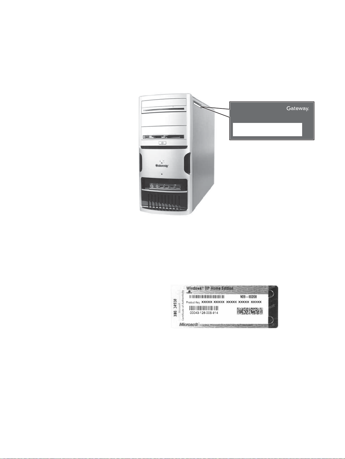
The label on the side of your computer case contains information that identifies
your computer model and serial number. Gateway Customer Care will need this
information if you call for assistance.
Gateway contact information
O
n
l
i
n
e
T
e
s
c
u
h
p
p
S
u
o
p
r
t
p
:
o
T
r
e
t
c
P
h
h
o
S
u
n
p
e
:
p
(
o
U
r
.
t
S
H
.
)
o
(
C
u
a
r
s
n
:
a
d
a
)
9
0
0
4
3
9
4
Online support:
Tech Support Phone: (U.S.)
Tech Support Hours:
(Canada)
9004394
Microsoft Certificate of Authenticity
The Microsoft Certificate of Authenticity label found on the back or side of your
computer includes the product key code for your operating system. If you ever
reinstall Windows from the installation CD or DVD, you will need to enter these
numbers to activate Windows.
3
Page 8

CHAPTER 1: About This Reference www.gateway.com
4
Page 9

CHAPTER 2
Hardware Features
•Front
•Back
5
Page 10
CHAPTER 2: Hardware Features www.gateway.com
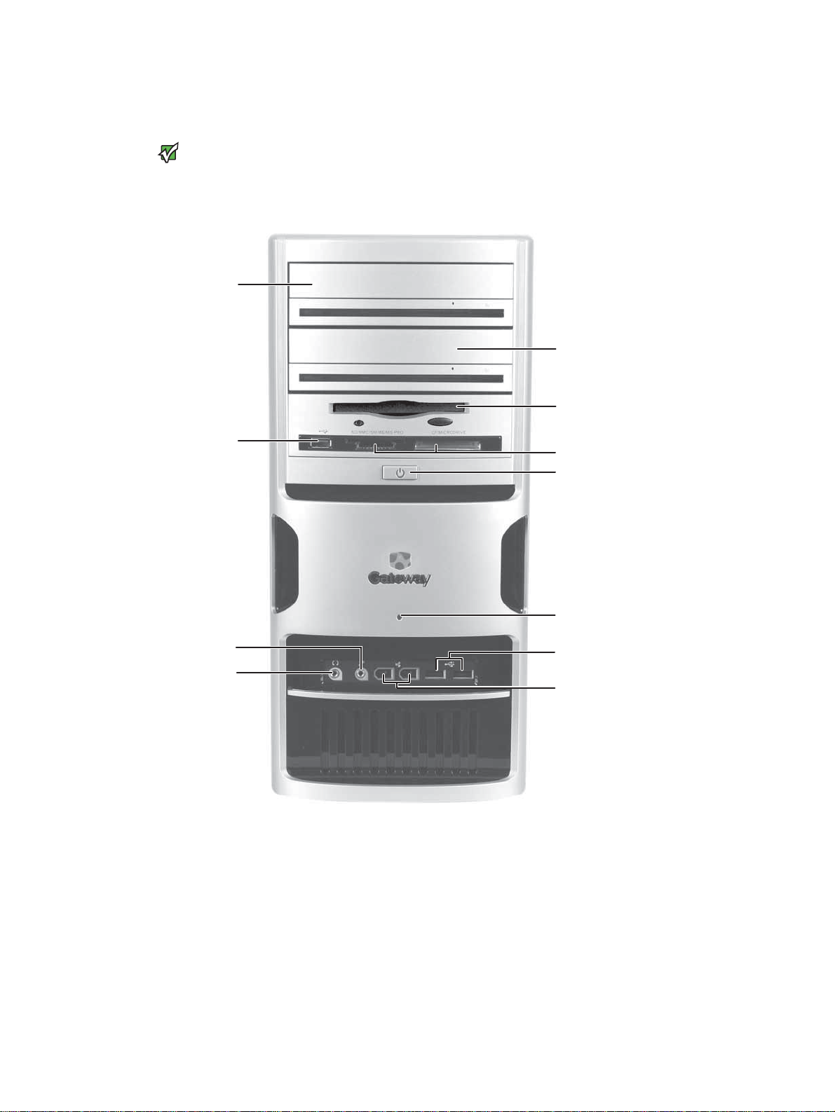
Front
Your computer hardware options and
Important
port locations may vary from the
illustration below.
DVD/CD drive
USB port
(optional)
DVD/CD drive
(optional)
Diskette drive
(optional)
Memory card reader
(optional)
Power button/ power
indicator
Microphone jack
Headphone jack
Hard drive indicator
USB ports (optional)
IEEE 1394 ports
(optional)
6
Page 11
www.gateway.com
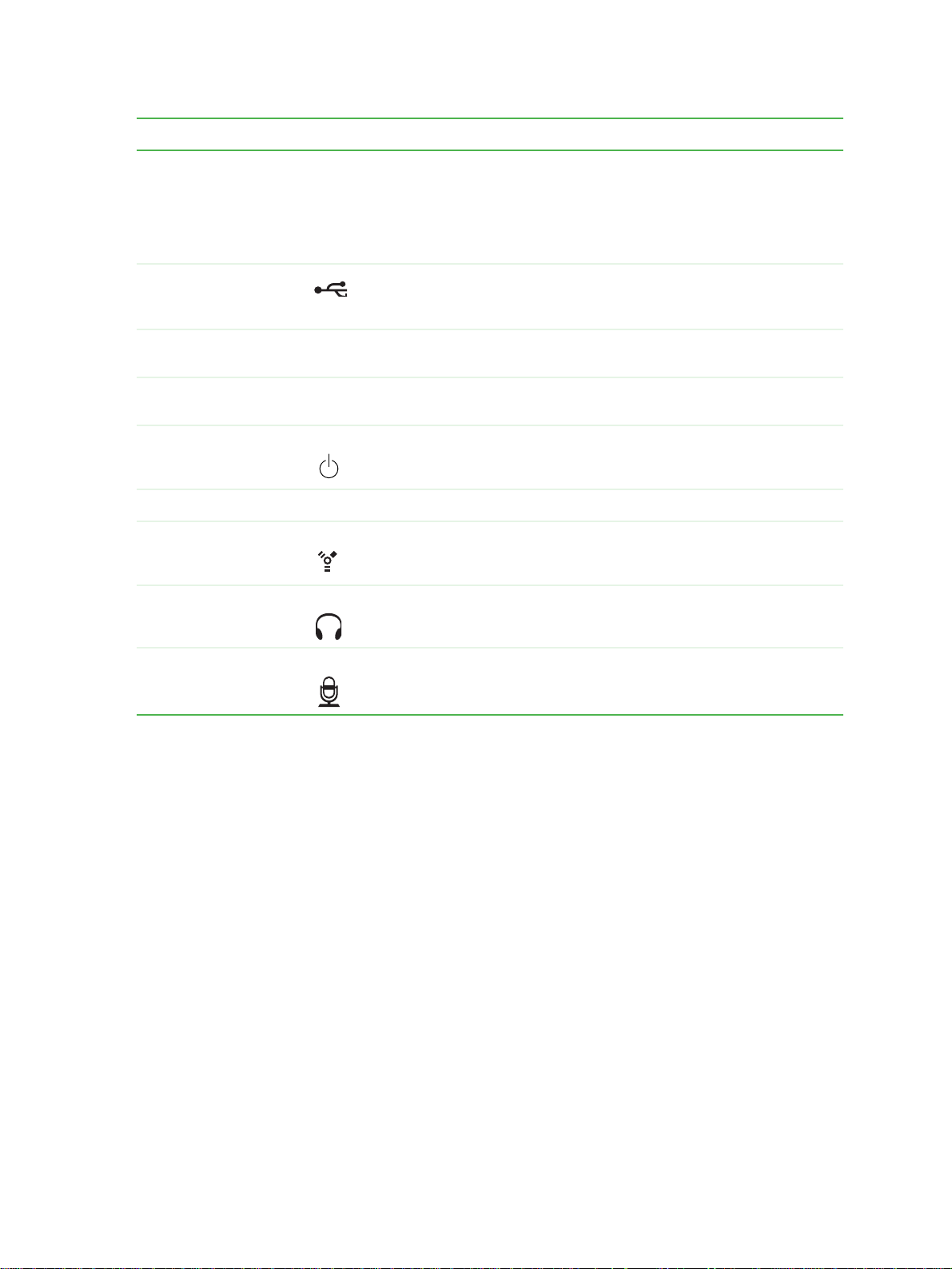
Component Icon Description
Front
DVD/CD drive
Use this drive to listen to audio CDs, install games and programs,
watch DVDs, and store large files onto recordable discs (depending
on drive type).
This drive may be a CD, recordable CD, DVD, or recordable DVD drive.
To identify your d rive typ e and f or more information about your drive , see
your user guide.
USB ports (optional) Plug a USB (Universal Serial Bus) device (such as a USB printer,
scanner , ca mera , k e yboa rd, or mouse ) into one o f th ese p orts. F or mo re
information, see your user guide.
Diskette drive
Insert a standard 3.5-inch diskette into the optional diskette drive.
(optional)
Memory card reader
(optional)
Power button and
power indicator
Insert a memory card from a digital camera, MP3 player, PDA, cellular
telephone, or other devices into the memory card reader.
Press this button to turn the power on or off. You can also configure
the power button to operate in Standby/Resume mode or Hibernate
mode. The power indicator lights when the computer is turned on.
Hard drive indicator Lights when the hard drive is in use.
IEEE 1394 ports
(optional)
Plug IEEE 1394 (also known as Firewire
digital camcorder) into these 6-pin IEEE 1394 ports. For more
®
or i.Link®) devices (such as a
information, see your user guide.
Headphone jack Plug powered, analog front speakers, an external amplifier, or
headphones into this jack. This jack is color-coded orange.
Microphone jack Plug a microphone into this jack. This jack is color-coded red or pink.
7
Page 12
CHAPTER 2: Hardware Features www.gateway.com
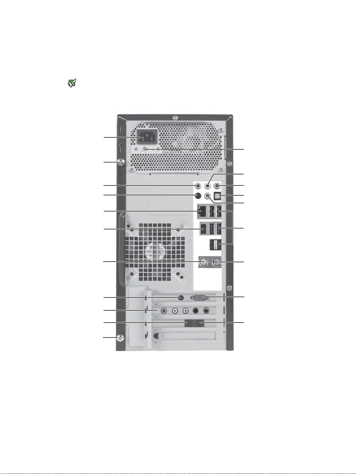
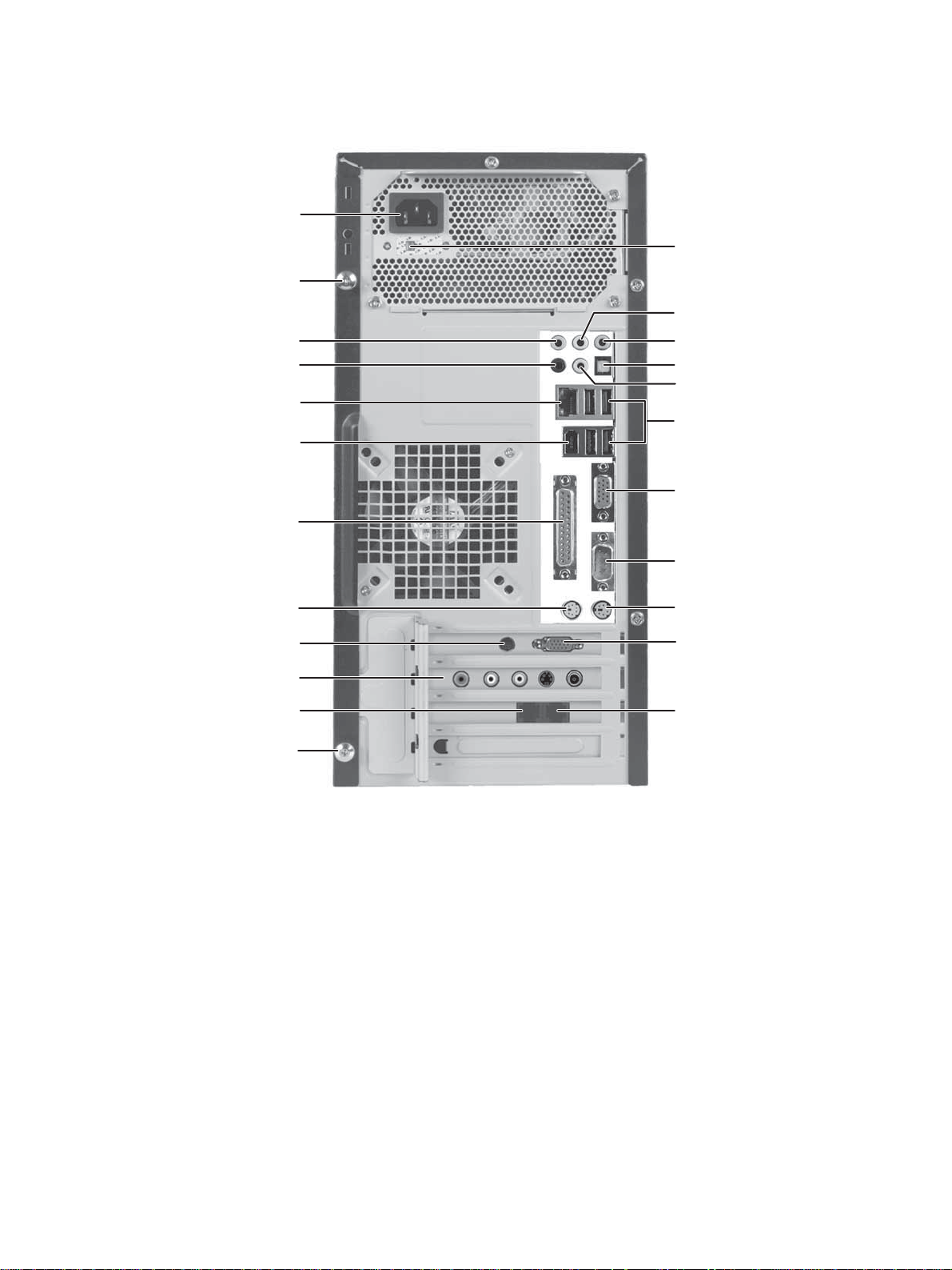
Back
Your computer matches one of the two following illustrations, and includes the
components listed.
Your computer hardware options and
Important
port locations may vary from the
illustrations below.
Power connector
Case cover thumbscrew
Audio in/side speaker jack
Surround left/right speaker jack
Ethernet (network) jack
IEEE 1394/FireWire™/
i.Link™ port
Voltage switch
Headphone/front speaker jack
Microphone jack
S/PDIF jack (optional)
Center/subwoofer jack
USB ports
PS/2 mouse port
S-Video out jack
(optional)
TV tuner (optional)
Telephone jack
Case cover thumbscrew
PS/2 keyboard port
Monitor port
Modem (line) jack
8
Page 13
www.gateway.com
Case cover thumbscrew
Audio in/side speaker jack
Surround left/right speaker
Ethernet (network) jack
Power connector
jack
IEEE 1394/FireWire™/
i.Link™ port
Parallel port
Back
Voltage switch
Headphone/front speaker jack
Microphone jack
S/PDIF jack (optional)
Center/subwoofer jack
USB ports
Monitor port
PS/2 mouse port
S-Video out jack
(optional)
TV tuner (optional)
Telephone jack
Case cover thumbscrew
Serial port
PS/2 keyboard port
Monitor port
(optional)
Modem jack
9
Page 14
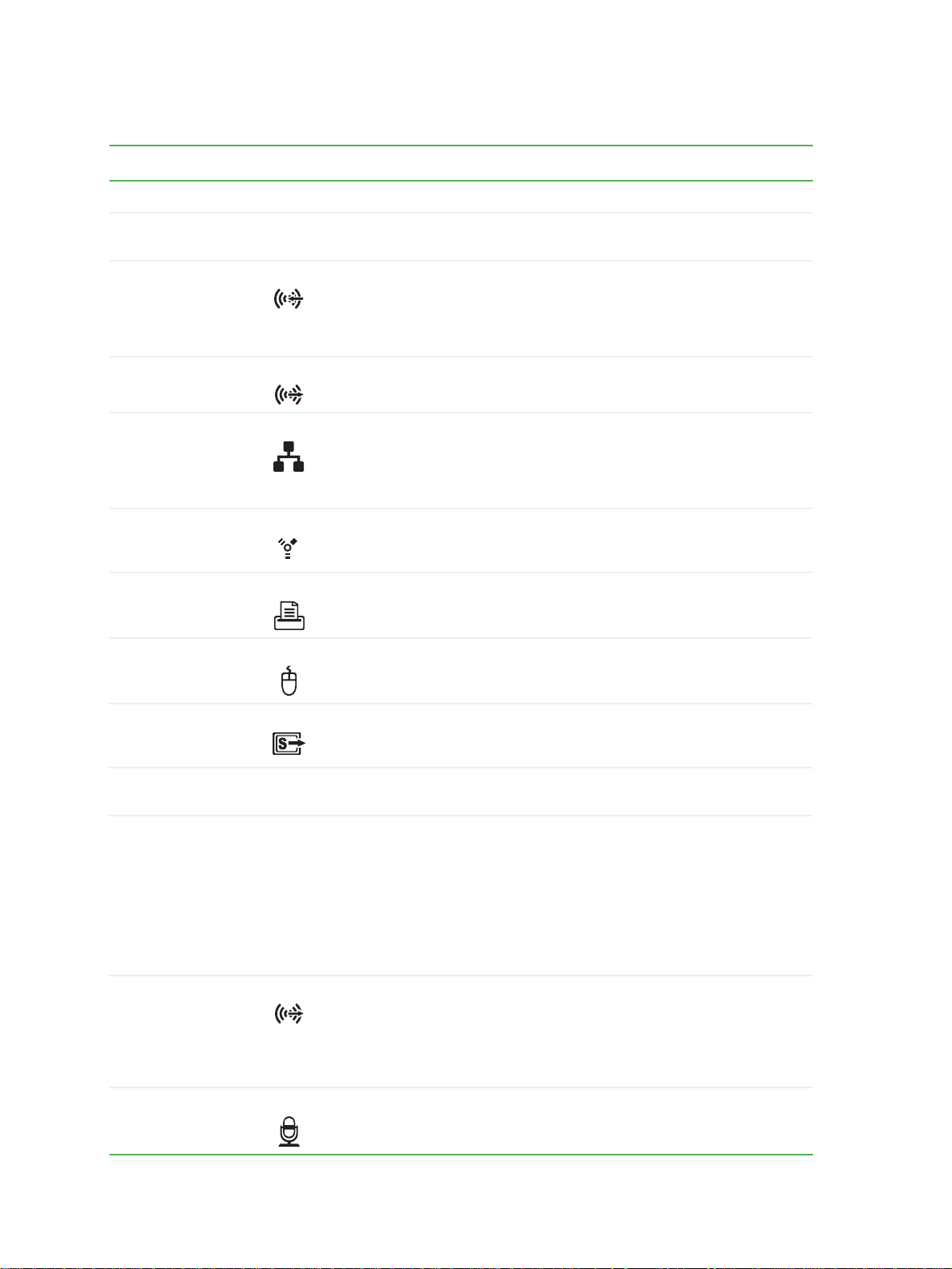
CHAPTER 2: Hardware Features www.gateway.com
Available ports may vary, depending on your model.
Component Icon Description
Power connector Plug the power cord into this connector.
Case cover
thumbscrews
Audio input (Line
in) jack (blue plug)
-ORSide speaker jack
Center/subwoofer
jack (orange plug)
Ethernet
(network) jack
IEEE 1394 ports Plug IEEE 1394 (also known as Firewire
Parallel port Plug a parallel device (such as a printer) into this port. For more
PS/2 mouse port Plug a PS/2 mouse into this port.
Remove these screws before opening the case.
This jack is user configurable for one of the following:
Stereo in: Plug an external audio input source (such as a stereo) into
this jack so you can record sound on your computer (Default).
Stereo out: Plug your side left and right speakers into this jack.
For information on configuring this jack, see your user guide.
Plug your center speaker and subwoofer into this jack.
For information on configuring this jack, see your user guide.
Plug an Ethernet network cable or a device (such as a DSL or cable
modem for a broadband Internet connection) into this jack.
For more information, see “Learning about the Internet” in your User
Guide which has been incl uded on yo ur hard drive. To access thi s guide,
click Start, All Programs, then click Gateway Documentation.
®
digital camcorder) into these 6-pin IEEE 1394 ports. For more
information, see your user guide.
information, see your user guide.
or i.Link®) devices (such as a
S-Video (TV) out
jack
(optional)
Telephone
(PHONE) jack
Voltage switch Before turning on your computer, make sure that this switch is in the
Headphone/
analog speakers
jack (green plug)
-ORFront speakers
jack
Microphone jack
(pink plug)
Plug a standard S-Video device (such as a television) into this optional
jack. Plug the other end of the cable into an S-Video jack on a television.
Plug a telephone’s cable into this jack after connecting the modem
(LINE) jack. For more information on modems, see your user guide.
correct position for the correct power available. The switch is preset at
the factory with the correct voltage for your area.
In the United States, the utility power is supplied at a nominal 115 volts
at 60 Hz. The power supply should always be set to this when your
computer is operating in the United States. In other areas of the world,
such as Europe, t he util ity pow er is suppli ed at 23 0 volts at 50 Hz . If you r
computer is operating in an environment such as this, the voltage
switch should be moved to 230.
This jack is user configurable for one of the following:
Headphone: Plug headphones or amplified speakers into this jack
(Default).
Stereo out: Plug your front left and right speakers into this jack.
For information on configuring this jack, see your user guide.
Plug a microphone into this jack.
10
Page 15
www.gateway.com
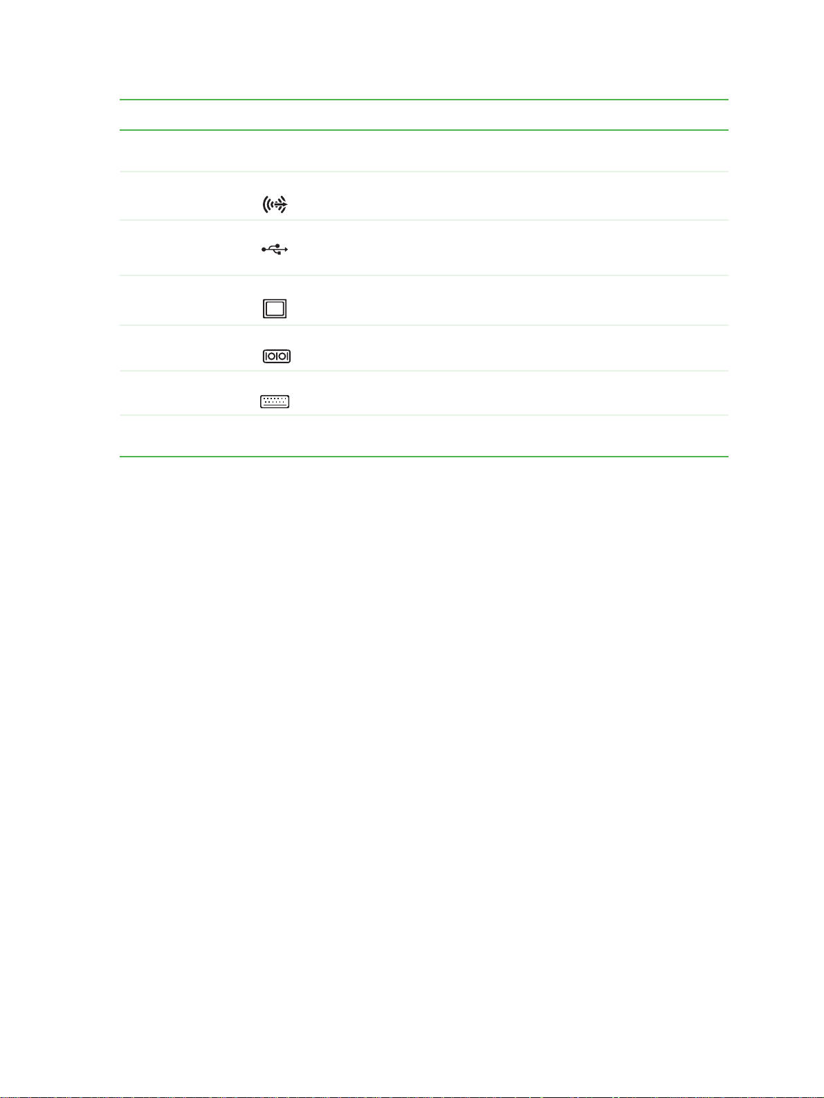
Component Icon Description
Back
S/PDIF optical
audio jack
Rear speaker jack
(black plug)
USB ports Plug USB (Universal Serial Bus) devices (such as a USB Iomega™ Zip™
Monitor port Plug a monitor into this port.
Serial port Plug a serial device into this port.
PS/2 keyboard
port
Modem (LINE) jack Plug a modem cable into this jack. For more information on modems,
Plug an S/PDIF optical audio connection to this jack.
Plug your right rear and left rear speakers into this jack.
For information on configuring this jack, see your user guide.
drive, printer, scanner, camera, keyboard, or mouse) into these ports.
For more information, see your user guide.
Plug a PS/2 keyboard into this port.
see your user guide.
11
Page 16

CHAPTER 2: Hardware Features www.gateway.com
12
Page 17

CHAPTER 3
Maintenance Basics
• Preventing static electricity discharge
• Opening the case
• Closing the case
• Installing memory
• Replacing the system battery
• Adding or replacing a CD or DVD drive
• Replacing the memory card reader
• Adding or replacing a hard drive
• Replacing the front fan
• Replacing the rear fan
• Replacing the power supply
• Replacing the heat sink and processor
• Replacing the I/O board
• Adding or replacing an expansion card
• Replacing the system board
13
Page 18

CHAPTER 3: Maintenance Basics www.gateway.com
Preventing static electricity discharge
To avoid exposure to dangerous electrical
voltages and moving parts, turn off your
computer and unplug the power cord
and modem and network cables before
ESD can permanently damage
electrostatic discharge-sensitive
components in your computer. Prevent
ESD damage by following ESD guidelines
every time you open the computer case.
To prevent risk of electric shock, do not
insert any object in to the vent holes of the
Warning
opening the case.
Caution
Wa rning
power supply.
The components inside your computer are extremely sensitive to static
electricity, also known as electrostatic discharge (ESD).
Before opening the computer case, follow these guidelines:
■ Turn off your computer.
■ Wear a grounding wrist strap (available at most electronics stores) and
attach it to a bare metal part of your computer.
■ Touch a bare metal surface on the back of the computer.
■ Unplug the power cord and the modem and network cables.
Before working with computer components, follow these guidelines:
■ Avoid static-causing surfaces such as carpeted floors, plastic, and packing
foam.
■ Remove components from their antistatic bags only when you are ready
to use them. Do not lay components on the outside of antistatic bags
because only the inside of the bags provide electrostatic protection.
■ Always hold expansion cards by their edges or their metal mounting
brackets. Avoid touching the edge connectors and components on the
cards. Never slide expansion cards or components over any surface.
Opening the case
Removing the side panel
To avoid exposure to dangerous electrical
voltages and moving parts, turn off your
computer, then unplug the power cord
and modem cable before opening the
Wa rning
case.
Your computer case provides easy access to internal components.
To remove the side panel:
1 Follow the instructions in “Preventing static electricity discharge” on
page 14.
2 Shut down your computer, then disconnect the power cord and modem,
network, and all peripheral device cables.
3 Press the power button for ten seconds to drain any residual power from
your computer.
14
Page 19

www.gateway.com
Opening the case
4 Remove the two thumbscrews on the side panel cover.
Thumbscrews
Removing the front bezel
5 Swing the side panel away from the back of your computer, then pull the
panel off.
To remove the front bezel:
■ Press the three bezel retention tabs, then swing the right side of the front
bezel away from the computer and remove it.
Tab s
15
Page 20

CHAPTER 3: Maintenance Basics www.gateway.com
Closing the case
Replacing the front bezel
To replace the front bezel:
1 Slide the tabs on the left side of the bezel into the slots in the left side of
the computer.
2 Swing the right side of the bezel in to insert the tabs on the right side of
the bezel into the slots on the right side of the computer.
3 Press the right side of the bezel firmly until it snaps into place.
Replacing the side panel
To replace the side panel:
1 Make sure that all of the internal cables are arranged inside the computer
so they will not be pinched when you close the computer.
2 Insert the front edge of the side panel into the inside front edge of the
computer, then swing the side panel in toward the back of the computer
to secure it into place.
Thumb screws
16
3 Replace the side panel thumbscrews.
4 Reconnect the cables and power cord.
Page 21

www.gateway.com
Installing memory
Installing memory
When you upgrade the computer memory, make sure that you install the correct
type of memory module for your computer. Your computer uses DIMM memory.
To install or replace DIMM memory:
1 Remove the side panel by following the instructions in “Removing the side
panel” on page 14.
2 For more stability, place your computer on its side. To avoid scratching the
case, place it on a towel or other non-abrasive surface.
3 Find the memory module banks on your system board.
4 If you are removing a DIMM from the memory module bank, gently pull
the plastic tabs away from the sides of the memory module and remove it.
- OR -
If you are adding a DIMM to an empty memory module bank, gently pull
the plastic tabs away from the sides of the memory module bank.
5 Align the notches on the new DIMM with the notches on the memory
module bank and press the module firmly into the bank. The tabs on the
sides of the memory module should secure the memory module
automatically. When the module is secure, you hear a click.
6 Replace the side panel by following the instructions in “Replacing the side
panel” on page 16.
7 Return your computer to its upright position.
17
Page 22

CHAPTER 3: Maintenance Basics www.gateway.com
8 Reconnect the cables and the power cord.
9 Turn on your computer. Windows starts and the Windows desktop
appears.
10 Click Start, Control Panel, then click Performance and Maintenance (if
in Category view). Click/Double-click System. The amount of memory in
your computer is shown at the bottom of the System Properties dialog box
in the General tab.
Replacing the system battery
Danger of explosion if battery is
Replace only with the same or equivalent
type recommended by the manufacturer.
Dispose of used batteries following the
Your computer’s battery location may
manufacturer’s instructions.
vary from the illustration below.
Warning
incorrectly replaced.
Important
If the computer clock does not keep time or the settings in the BIOS Setup utility
are not saved when you turn off your computer, replace the system battery. Use
a battery of the same size and voltage as the original battery that was in your
computer.
To replace the battery:
1 Restart your computer.
2 During the restart, press and hold the F1 key. The main menu of the
BIOS Setup utility opens.
3 Write down all the values in the menus and submenus, then exit from the
utility.
4 Shut down your computer.
5 Remove the side panel by following the instructions in “Removing the side
panel” on page 14.
6 For more stability, place your computer on its side. To avoid scratching the
case, place it on a towel or other non-abrasive surface.
7 Locate the old battery on the system board and note its orientation. You
will need to install the new battery the same way.
8 Push the battery release tab. The battery pops out of the socket.
18
Battery
Battery release tab
Page 23

www.gateway.com
9 Make sure that the positive (+) side of the new battery is facing up, then
press the battery into the socket until it snaps into place.
10 Replace the side panel by following the instructions in “Replacing the side
panel” on page 16.
11 Reconnect all external cables and the power cord.
12 Turn on your computer.
13 Open the BIOS Setup utility.
14 In the BIOS Setup utility, restore any settings that you wrote down in
Step 3.
15 Save all your settings and exit the BIOS Setup utility.
Adding or replacing a CD or DVD drive
Adding or replacing a CD or DVD drive
You need a Phillips screwdriver to add or
The color and shape of your replacement
drive’s front cover may vary from your
Tips & Tricks
replace a CD or DVD drive.
Important
original drive.
To add replace a CD or DVD drive:
1 Remove the side panel by following the instructions in “Removing the side
panel” on page 14.
2 Remove the front bezel by following the instructions in “Removing the
front bezel” on page 15.
3 If you are installing a new drive (not replacing an old one), remove the two
drive retention screws in the drive bay, then go to Step 7. For the location
of the screws, see the photo in Step 6.
4 If you are replacing an existing drive, disconnect the cables from the drive,
noting their locations and orientation. You will reconnect the cables after
you install the new drive. (CD/DVD drive shown.)
5 Note any jumper settings on the old drive and set the jumper on the new
drive to be the same.
19
Page 24

CHAPTER 3: Maintenance Basics www.gateway.com
6 Remove the two drive retention screws, then slide the drive forward and
out of the drive bay.
Drive retention screws
7 Slide the new drive into the drive bay, line up the screw holes on the drive
bay with the screw holes on the drive, then replace the two drive retention
screws.
8 Reconnect the drive cables using your notes from Step 4.
9 Replace the front bezel by following the instructions in “Replacing the
front bezel” on page 16.
10 Replace the side panel by following the instructions in “Replacing the side
panel” on page 16.
Replacing the memory card reader
You need a Phillips screwdriver to replace
The color and shape of your replacement
card reader’s front cover may vary from
Tips & Tricks
the memory card reader.
Important
your original card reader.
To replace the memory card reader:
1 Remove the side panel by following the instructions in “Removing the side
panel” on page 14.
2 Remove the front bezel by following the instructions in “Removing the
front bezel” on page 15.
3 If you are installing a new card reader (not replacing an old one), remove
the two drive retention screws in the drive bay, then go to Step 6. For the
location of the screws, see the photo in Step 6.
Drive retention screws
20
Page 25

www.gateway.com
Adding or replacing a hard drive
4 Remove the two drive retention screws, disconnect the card reader’s data
cable from the system board, then slide the drive forward and out of the
drive bay.
Screws
5 Slide the card reader out of the case.
6 Slide the new card reader into the bay from the front of the case.
7 Use the screws you removed previously to secure the card reader to the
bay.
8 Connect the new card reader’s data cable to the system board.
9 Reinstall the bezel by following the instructions in “Replacing the front
bezel” on page 16.
10 Reinstall the computer case’s side panel by following the instructions in
“Replacing the side panel” on page 16.
Adding or replacing a hard drive
To add or replace a hard drive:
You need a Phillips screwdriver to add or
Tips & Tricks
replace a hard drive.
1 Remove the side panel by following the instructions in “Removing the side
panel” on page 14.
2 If you are adding a new drive, go to Step 4. If you are replacing an existing
drive, go to the next step.
Screws
21
Page 26

CHAPTER 3: Maintenance Basics www.gateway.com
3 Disconnect the drive cables, noting their locations and orientation. (You
will reconnect the cables after you install the new drive.)
4 Pull the front fan assembly away from the system board, then remove it.
22
5 Disconnect the fan cable from the system board.
Page 27

www.gateway.com
Adding or replacing a hard drive
6 Remove the hard drive bay screw.
Hard drive
bay screw
7 Remove the hard drive bay from your computer. You may need to work
the bay out of your computer by rocking the bay back and forth.
8 If you are replacing an old drive, remove the four screws that secure the
hard drive to the hard drive bay, then remove the hard drive from the bay.
ScrewsScrews
9 If you are adding a new drive (not replacing an old one), remove the four
screws (two on each side) from the empty hard drive bay.
23
Page 28
CHAPTER 3: Maintenance Basics www.gateway.com
10 If you are replacing a drive, note any jumper settings on the old drive and
set the jumper on the new drive to be the same. If you are adding a new
drive, set the jumper as instructed by the drive’s user guide.
Jumper
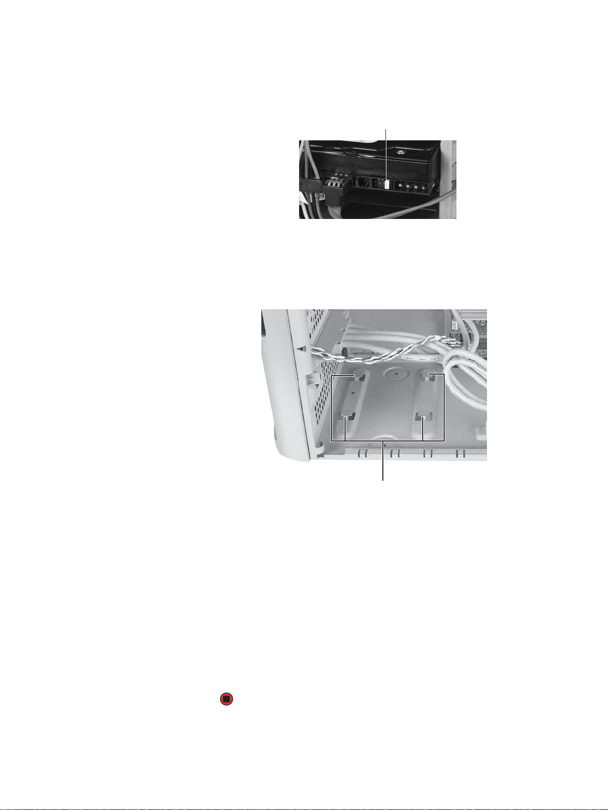
11 Slide the new drive into the drive bay, then secure the drive to the bay
using the four screws you removed previously.
12 Slide the drive bay back into your computer, making sure that the tabs on
the bottom of the bay align with and slide into the slots on the bottom
of your computer.
24
Hard drive bay
mounting slots
13 Secure the drive bay to your computer using the screw you removed
previously.
14 Connect the drive cables. If you are replacing a drive, use your notes from
Step 3.
15 Replace the side panel by following the instructions in “Replacing the side
panel” on page 16.
16 Reconnect all external cables and the power cord.
17 Turn on your computer.
18 If Windows does not start, install Windows using the operating system CD
that came with your computer, then install the drivers and applications by
following any instructions printed on the CD.
Page 29

www.gateway.com
Replacing the front fan
Replacing the front fan
You need a Phillips screwdriver to replace
Tips & Tricks
the front fan.
To replace the front fan:
1 Remove the side panel by following the instructions in “Removing the side
panel” on page 14.
2 Pull the front fan away from the system board, then remove it.
3 Disconnect the fan cable from the system board.
4 Connect the new fan cable to the system board, then insert the new fan
into place.
5 Replace the side panel by following the instructions in “Replacing the side
panel” on page 16.
25
Page 30

CHAPTER 3: Maintenance Basics www.gateway.com
Replacing the rear fan
You need a Phillips screwdriver to replace
Tips & Tricks
the rear fan.
To replace the rear fan:
1 Remove the side panel by following the instructions in “Removing the side
panel” on page 14.
2 Disconnect the fan from the system board.
3 Remove the four screws on the outside of the case that secure the fan to
the back of the case, then remove the fan.
26
Screws Screws
4 Place the new fan on the back of your computer, then replace the screws
that secure it to the back cover.
5 Reconnect the fan cable to the system board.
6 Replace the side panel by following the instructions in “Replacing the side
panel” on page 16.
7 Reconnect all external cables and the power cord.
8 Turn on your computer.
Page 31

www.gateway.com
Replacing the power supply
Replacing the power supply
You need a Phillips screwdriver to replace
Tips & Tricks
the power supply.
To replace the power supply:
1 Remove the side panel by following the instructions in “Removing the side
panel” on page 14.
2 Disconnect the power supply cables from all components (such as hard
drives, CD or DVD drives, and the system board), noting their locations and
orientation. (You will reconnect the cables after you install the new power
supply.)
3 Remove the three screws that secure the power supply to your computer.
Screws
4 Slide the power supply away from the back of your computer, then pull
it down and remove it.
5 Install the new power supply into the case, then install the three screws
to secure the power supply to the case.
6 Reconnect the power supply cables using your notes from Step 2.
7 Replace the side panel by following the instructions in “Replacing the side
panel” on page 16.
27
Page 32

CHAPTER 3: Maintenance Basics www.gateway.com
Replacing the heat sink and processor
You need a Phillips screwdriver to replace
Tips & Tricks
the heat sink.
To replace the heat sink and processor:
1 Remove the side panel by following the instructions in “Removing the side
panel” on page 14.
2 For more stability, place your computer on its side. To avoid scratching the
case, place it on a towel or other non-abrasive surface.
3 Pull the front fan away from the system board, then remove it.
4 Disconnect the fan cable from the system board.
28
Page 33

www.gateway.com
Replacing the heat sink and processor
5 Loosen the four screws that secure the heat sink to the system board, then
remove the heat sink and place it on a stable surface with the flat surface
of the heat sink (the side with the thermal grease) up.
Screws
6 Release the processor by pushing down on the lever and then lifting it
Screws
completely up.
7 Remove the processor from the system board.
8 Install the new processor onto the system board making sure that Pin 1
on the processor (indicated by the silk-screened arrow on the corner of
the processor) aligns with Pin 1 on the processor socket (indicated by the
absence of a pin hole in the processor socket), then return the lever to its
locked position.
9 If this is a new heat sink, remove the strip on the heat sink that covers the
gray thermal grease. If you are re-using a heat sink, then re-apply a small
bead of thermal grease to the surface that contacts the processor.
10 Place the heat sink on the system board, then tighten the screws that
secure it to the system board.
11 Connect the fan cable to the system board, then insert the fan into place.
12 Replace the side panel by following the instructions in “Replacing the side
panel” on page 16.
29
Page 34

CHAPTER 3: Maintenance Basics www.gateway.com
Replacing the I/O board
The color and shape of your replacement
Important
I/O panel may vary from your original
I/O panel..
To replace the front I/O panel:
1 Remove the side panel by following the instructions in “Removing the side
panel” on page 14.
2 Remove the bezel by following the instructions in “Removing the front
bezel” on page 15.
3 Disconnect the cable from the I/O panel.
4 Remove the screw that secures the I/O panel to your computer, then
remove the I/O panel from your computer.
Screw
5 Insert the new I/O panel into your computer, then replace the screw.
6 Connect the I/O panel cable to the new I/O panel.
7 Replace the front bezel by following the instructions in “Replacing the
front bezel” on page 16.
8 Replace the side panel by following the instructions in “Replacing the side
panel” on page 16.
30
Page 35

www.gateway.com
Adding or replacing an expansion card
To add or replace an expansion card:
1 Remove the side panel by following the instructions in “Removing the side
panel” on page 14.
2 If you are replacing an expansion card, go to the next step. If you are
adding a new expansion card, go to Step 4.
3 Disconnect any cables that are attached to the card, noting their locations
and orientation. (You may need to reconnect the cables after you install
the new card.)
4 Open the card retention lever.
Adding or replacing an expansion card
Card retention lever
Do not touch the contacts on the bottom
part of the expansion card. Touching the
contacts can cause electrostatic damage
Caution
to the card.
5 Remove the old expansion card. You can slightly seesaw the card
end-to-end to loosen the card, but do not bend the card sideways.
6 Install the new card into the expansion slot. You can slightly seesaw the
card end-to-end to help insert the card, but do not bend the card
sideways.
7 If you have just replaced an expansion card, reconnect the expansion card
cables (if any) using your notes from Step 3. If you have added a new
expansion card, connect its cables according to its user guide.
8 Replace the side panel.
31
Page 36

CHAPTER 3: Maintenance Basics www.gateway.com
Replacing the system board
To replace the system board:
1 Remove the side panel by following the instructions in “Removing the side
panel” on page 14.
2 Disconnect any expansion card cables from the cards and from the system
board, noting their locations and orientation. (You will reconnect the
cables after you reinstall the cards.) You can also mark the cables with tape
labels to simplify reconnecting cables later.
3 Open the card retention lever.
Card retention lever
4 Remove any expansion cards. You can slightly seesaw the card end-to-end
to loosen the card, but do not bend the card sideways.
32
Page 37

www.gateway.com
Replacing the system board
5 Pull the front fan away from the system board, then remove it.
6 Disconnect the fan cable from the system board.
7 Find the memory module banks on your system board.
8 Gently pull the plastic tabs away from the sides of the memory modules,
then remove them.
9 Disconnect the power and data cables from the system board, noting their
locations and orientation. (You will reconnect the cables after you install
the new board.)
33
Page 38

CHAPTER 3: Maintenance Basics www.gateway.com
10 Remove the three screws that secure the power supply to your computer.
Screws
11 Slide the power supply away from the back of your computer, then pull
it down and remove it.
12 Remove the seven system board screws.
Screws
Screws
13 Lift the system board up and out of the case.
14 Align the new system board on the screw holes in the case, then secure
it into the case with the screws.
15 If your replacement system board does not include a processor, go to
Step 16.
-OR-
34
If your replacement system board includes a processor, go to Step 21.
Page 39

www.gateway.com
Replacing the system board
16 Loosen the four screws that secure the heat sink to the system board, then
remove the heat sink and place it on a stable surface with the flat surface
of the heat sink (the side with the thermal grease) up.
Screws
17 Release the processor from the old system board by pushing down on the
Screws
lever and then lifting it completely up.
18 Remove the processor from the old system board.
19 Install the processor onto the new system board making sure that Pin 1
on the processor (indicated by the silk-screened arrow on the corner of
the processor) aligns with Pin 1 on the processor socket (indicated by the
absence of a pin hole in the processor socket), then return the lever to its
locked position.
20 Place the heat sink over the processor, then tighten the screws that secure
it to the system board.
21 Install the power supply into the case, then install the three screws to
secure the power supply to the case.
22 Connect the power and data cables using your notes from Step 9.
23 Install the memory you removed previously.
24 Connect the fan cable to the system board, then insert the fan into place.
35
Page 40

CHAPTER 3: Maintenance Basics www.gateway.com
25 Reinstall any expansion cards you removed.
26 Replace the side panel by following the instructions in “Replacing the side
panel” on page 16.
36
Page 41

CHAPTER 4
Configuring Drives for RAID
•About RAID
•Configuring RAID
•Getting help
37
Page 42

CHAPTER 4: Configuring Drives for RAID www.gateway.com
About RAID
RAID (Redundant Array of Inexpensive/Independent Disks) lets your computer use
multiple hard drives more efficiently. Your computer supports RAID 0, RAID 1,
RAID 5, and RAID 10.
RAID for performance
RAID 0 lets your computer see multiple hard drives as a single drive. This type
of RAID can increase file access speeds, which is important if you work with
video editing, sound editing, and high-performance games. RAID 0 is also an
affordable way to increase your total file storage capacity.
How it increases performance
The more drives you have in your RAID 0 array, the faster the potential drive
reading performance. All hard drives have limitations on how fast they can read
and write files. If half a file is stored on one RAID 0 drive and the other half on
another RAID 0 drive, each drive only has to read half of the file. So, the entire
file is accessed by the computer up to twice as fast (using a two-drive RAID 0
array). In a three-drive RAID 0 array, if the file is evenly distributed among the
drives, each drive must read only a third of the file, and so on. If the entire file
happens to be stored on only one of the drives, the file is accessed at the same
speed as if it were on a standard hard drive setup. Dividing up files between
multiple hard drives like this is called striping.
How it makes file storage cheaper
Because RAID 0 lets your computer see multiple hard drives as a single drive,
you can install several lower capacity (less expensive) drives and have the same
single-drive storage simplicity and capacity as a larger, more expensive hard
drive.
Drawbacks
Unfortunately, RAID 0 lets multiple drives behave as one in another way. If part
of the array fails (such as a hard drive crashing), the entire array fails. Because
the drives are treated like a single drive, parts of files (including operating
system files) can be spread across several drives, leaving the computer with only
file fragments if one drive fails. Also, because it is more likely that a hard drive
can fail in a multiple-drive RAID setup, regular and frequent backups are critical.
Another drawback is that RAID 0 treats each hard drive as if it has the storage
capacity of the smallest drive in the array. So if you have three drives (300 GB,
250 GB, and 200 GB) in a RAID 0 array, your computer only recognizes 600 GB
total capacity.
38
Page 43

www.gateway.com
RAID for security
About RAID
RAID 1 maintains a complete copy of a file set on each physical hard drive in
the array. Because each hard drive has a full copy of all files, your data and
applications are completely backed up. Maintaining simultaneous, complete
copies of files across multiple hard drives is called mirroring.
File reading performance (seek time) is increased using the same methods that
RAID 0 uses, although writing speed is the same as if writing to a single hard
drive.
For maximum reliability, you can use a separate hard drive controller for each
drive (called splitting or duplexing).
Drawback
RAID 1 treats the entire array as a single drive with the storage capacity of the
smallest physical drive in the array. So if you have three drives (300 GB, 250 GB,
and 200 GB) in a RAID 1 array, your computer only recognizes a single drive with
200 GB total capacity.
RAID for both: performance and security
RAID 5 uses mirroring across the drives, and striping (at the block level) with
on-the-fly error correction across all drives. Because of this error correction,
small file read/write errors can be quickly and automatically fixed without a
significant drop in system performance. RAID 5 offers good performance and
data redundancy.
RAID 10 (also called RAID 1+0 or RAID 1&0) contains sets of RAID 1 mirrors acting
as drives within a RAID 0 striping array. With this setup, all but one drive in the
array can fail, and the RAID would still be providing necessary data to the
computer.
Drawbacks
RAID 5 has the combined drawbacks of RAID 0 (one drive completely failing
results in total data loss) and and RAID 1 (array treated as one drive with capacity
of smallest physical drive).
RAID 10 treats the entire array as a single drive with the storage capacity of the
smallest drive in the array. So if you have four drives (350 GB, 300 GB, 250 GB,
and 200 GB) in a RAID 10 array, your computer only recognizes a single drive
with 200 GB total capacity.
39
Page 44
CHAPTER 4: Configuring Drives for RAID www.gateway.com
Configuring RAID
Enabling RAID
Although your computer is capable of using RAID, the RAID feature is not yet
enabled.
To enable RAID on your computer:
1 Start (or restart) your computer.
2 As soon as your computer turns on and the Gateway logo appears on the
screen, press F2. The BIOS Setup utility opens.
3 Select the Advanced menu, then select Drive Configuration.
4 Change the ATA/IDE M o de to Enhanced.
5 Change the SATA mode to RAID.
6 Press F10, then type Y to exit BIOS saving changes.
Creating a RAID volume
Now that RAID is enabled, you can access the RAID setup
Because RAID can be configured so many ways, this procedure covers only the
basics.
To configure RAID:
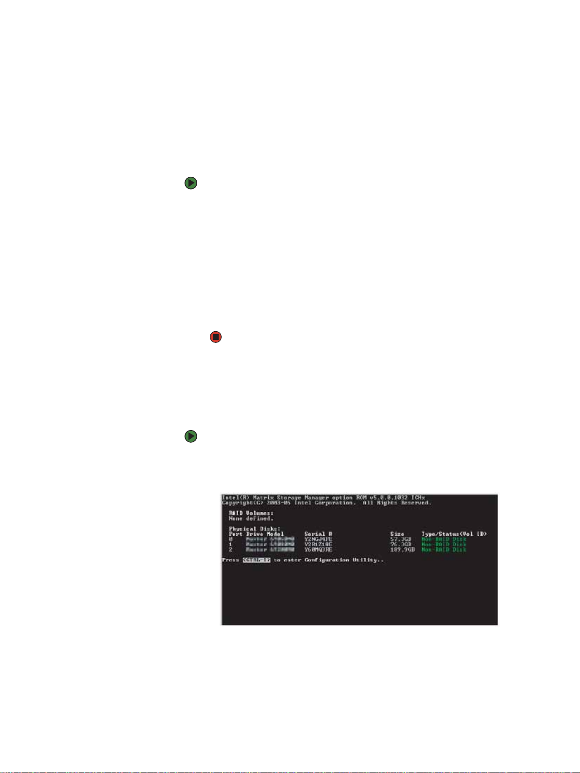
1 Start (or restart) your computer. During startup, the RAID option screen
appears. (Number and specifications of your drives may vary from the
example.)
40
Page 45

www.gateway.com
Configuring RAID
2 While the RAID option screen is open, press CTRL+i. The Matrix Storage
Manager opens.
3 Highlight 1. Create RAID Volume, then press ENTER. The CREATE VOLUME
MENU opens.
4 Change the following settings:
■ Name—Type a volume name (up to 16 characters) or use the
default name, then press ENTER.
■ RAID Level—Press ↑ or ↓ to select the RAID level, then press ENTER.
■ Select Disks—Press ↑ or ↓ to highlight drives, press the spacebar
to select (mark with a green triangle) each drive to use in the array,
then press E
■ Strip Size—If you have selected RAID 0, RAID 5, or RAID 10, select
NTER. You must select a minimum of two drives.
the strip value for the array, then press ENTER. Defaults: 218 KB for
RAID 0 and RAID 10, 64 KB for RAID 5. We recommend accepting
the default strip value.
■ Capacity—Type the volume capacity, or use the default capacity,
then press ENTER. We recommend using the default value (the
maximum capacity with the drives you selected).
5 Highlight Create Volume, then press ENTER. A warning appears.
6 Type Y. The RAID volume is created and the MAIN MENU opens.
7 Highlight 4. Exit, then press Enter. You exit the Matrix Storage Manager,
and your computer restarts.
41
Page 46

CHAPTER 4: Configuring Drives for RAID www.gateway.com
Deleting a RAID volume
Deleting a RAID volume deletes all files on that volume, including operating
system files.
To delete a RAID volume:
1 Start (or restart) your computer. During startup, the RAID option screen
appears.
2 While the RAID option screen is open, press CTRL+i. The Matrix Storage
Manager opens.
If your computer boots to RAID (to load
the operating system), deleting the RAID
volume will remove the operating
system, and you will not be able to start
Caution
your computer.
3 Highlight 2. Delete RAID Volume, then press ENTER. The DELETE VOLUME
MENU opens.
4 Press ↑ or ↓ to highlight the RAID volume you want to delete, then press
DELETE. A warning message appears.
5 Type Y to confirm volume deletion.
Resetting drives to non-RAID status
To troubleshoot or recover incompatible RAID configurations, failed RAID
volumes, or failed drives within a RAID volume, you can reset the drives to
non-RAID status until the problems can be resolved.
To reset drives to non-RAID status:
1 Start (or restart) your computer. During startup, the RAID option screen
appears.
2 While the RAID option screen is open, press CTRL+i. The Matrix Storage
Manager opens.
3 Highlight 3. Reset Disks to Non-RAID, then press ENTER. The RESET RAID
DATA menu opens.
42
4 Press ↑ or ↓ to highlight drives, press the spacebar to select (mark with a
green triangle) each drive you want to reset, then press E
NTER. A warning
message appears.
5 Type Y to confirm the drive reset.
Page 47

www.gateway.com
Getting help
Getting help
For more information on RAID concepts, configuration, and maintenance,
search for RAID FAQ information on the Gateway Technical Support Web site
(support.gateway.com
(support.intel.com
© 2006 Gateway, Inc. All rights reserved. Gateway and eMachines are trademarks
or registered trademarks of Gateway, Inc. in the United States and other
countries. All other brands and product names are trademarks or registered
trademarks of their respective companies.
) and the Intel Support & Downloads Web site
).
43
Page 48

CHAPTER 4: Configuring Drives for RAID www.gateway.com44Index
Page 49

www.gateway.com
Index
A
AC power connector 10
audio
audio in jack
center speaker jack 10
front speaker jack 10
headphone jack 10
line in jack 10
line out jack 10
microphone jack 7, 10
rear speaker jack 11
side speaker jack 10
subwoofer jack 10
audio in jack 10
10
B
battery
replacing
bezel
removing
replacing 16
broadband connection
connecting
18
15
10
C
cable modem
connecting
cards
adding expansion
replacing expansion 31
case
closing 16
opening 14
CD drive
adding
locating drive 7
replacing 19
Certificate of Authenticity 3
closing
computer case
front bezel 16
connecting
PS/2 keyboard 11
PS/2 mouse 10
to Ethernet network 10
to Internet 10
to network 10
connections
audio in
center speaker 10
digital camera 7, 11
digital video camera 7, 10
Ethernet 10
10
31
19
16
10
external audio 10
external speakers 10
Firewire 7, 10
front speaker 10
headphone 10
i.Link 7, 10
IEEE 1394 7, 10
keyboard 7, 11
line in 10
line out 10
microphone 7, 10
modem 10, 11
monitor 11
mouse 7, 10, 11
network 10
parallel 10
power 10
power cord 10
printer 7, 10, 11
PS/2 keyboard 11
PS/2 mouse 10
rear speakers 11
scanner 7, 11
side speaker 10
subwoofer 10
S-Video (TV) out 10
USB 7, 11
video camera 7, 10
Zip drive 7, 11
D
digital camera
locating USB port
digital video camera
locating IEEE 1394 port
DIMM
See memory
documentation
Using Your Computer
drives
7
CD
DVD 7
recordable CD 7
recordable DVD 7
DSL modem
connecting
duplexing 39
DVD drive
adding 19
locating drive 7
replacing 19
7, 11
7, 10
2
10
E
electrostatic discharge (ESD) 14
Ethernet jack 10
expansion card
adding 31
replacing 31
external audio jack 10
F
fan
replacing 25, 26
Firewire port 7, 10
front bezel
removing
replacing 16
front I/O panel
replacing 30
16
G
Gateway contact information 3
H
hard drive
adding
indicator 7
replacing 21
headphone jack 7, 10
heat sink
replacing 28
Hibernate mode 7
21
I
i.Link port 7, 10
IEEE 1394 port 7, 10
indicators
hard drive 7
power 7
installing
battery
front bezel 15
memory 17
side panel 14
system battery 18
18
J
jacks
See connections
K
keyboard
PS/2 port
USB port 7, 11
11
45
Page 50

Index www.gateway.com
L
label
Microsoft Certificate of
Authenticity
product 3
line in jack 10
line out jack 10
M
memory
adding
installing 17
replacing 17
memory card reader
locating
replacing 20
microphone jack 7, 10
Microsoft Certificate of
mirroring 39
modem
jack 10, 11
monitor
port 11
mouse
PS/2 port 10
USB port 7, 11
17
6
Authenticity
N
network jack 10
O
opening
computer case 14
front bezel 15
P
parallel port 10
ports
See connections
power
button
connector 10
Hibernate mode 7
indicator 7
Standby/Resume 7
power button 7
power supply
replacing 27
printer
parallel port 10
USB port 7, 11
PS/2 port
keyboard
7
11
3
3
mouse 10
R
RAID 38
creating a volume 40
deleting a volume 42
enabling 40
getting help 43
RAID 0 38
RAID 1 39
RAID 10 39
RAID 5 39
resetting a volume 42
RAM
See memory
recordable drive
locating 7
Resume mode 7
7
S
safety
static electricity 14
seek time 39
side panel
removing
replacing 14
speaker jack 10
splitting 39
Standby mode 7
starting
computer 7
static electricity 14
strip size 41
striping 38
S-Video (TV) out jack 10
system battery
replacing
system board
replacing
14
18
32
T
turning off computer 7
turning on computer 7
TV out (S-Video out) jack 10
U
USB port 7, 11
V
video
S-Video out jack
VGA port 11
voltage switch 10
10
W
Windows Product Key Code 3
Z
Zip drive port 11
46
Page 51

Page 52

MAN 6BAY MBTX CONS HW REF R2 7/06
 Loading...