

Page 1
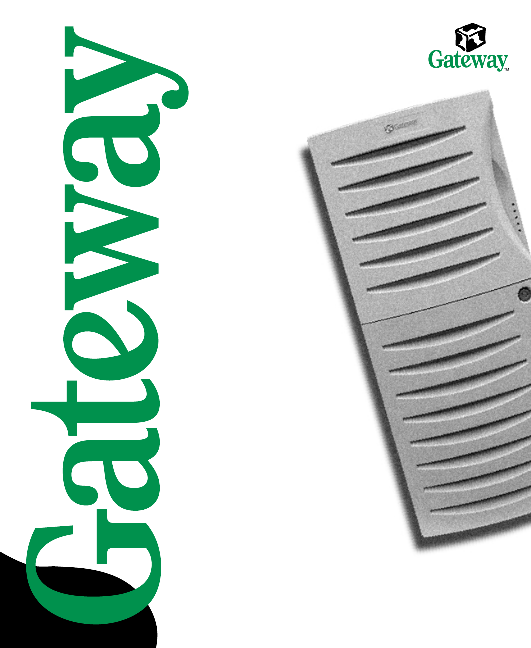
6400 Server
System Manual
Page 2

Contents
Preface..............................................................v
Conventionsusedinthismanual ....................................... v
Gettingadditionalinformation ..........................................vii
1 System Features ................................................1
Standardfeatures ...................................................1
Frontpanel ........................................................ 2
Rear panel . . . . . . . . . . . .............................................4
Systemboard ...................................................... 6
2 System Setup ...................................................9
Settingupyoursystem ...............................................9
Startingyoursystem ................................................ 10
UnderstandingthePower-OnSelf-Test ..............................12
Settinguptheoperatingsystem ....................................12
Turningoffyoursystem..............................................13
Resettingyoursystem ............................................... 14
3 Case Access ...................................................15
Preventingstaticelectricitydischarge ................................... 15
Openingthecase .................................................. 17
Removingthesidecover ......................................... 18
Removingthebezel .............................................19
Closingthecase ................................................... 20
Replacingthebezel .............................................20
Replacingthesidecover .........................................21
4 Replacing and Adding System Components ...................23
Replacingoraddingdrives ...........................................23
Preparingtoreplaceoraddadrive .................................23
Drivecablinginformation ......................................... 25
3.5-inchdisketteorCDdrives ..................................... 25
Harddrive ..................................................... 33
Replacingoraddingmemory .........................................37
Replacingoraddingaprocessor ...................................... 40
Adding an expansion card ............................................ 45
Replacingthebattery ...............................................47
Troubleshootingthebatteryinstallation .............................. 48
i
Page 3

Replacingthesystemboard ...........................................50
Replacingthepowersupply ...........................................55
Replacingthesystemfans ............................................58
Replacingthecontrol/LEDboard .......................................64
5 Using the BIOS Setup Utility ....................................67
AbouttheBIOSSetuputility...........................................67
UpdatingtheBIOS ..................................................69
Settingtheconfigurationswitches ......................................70
TheClearPasswordswitch ........................................70
TheClearCMOSswitch ..........................................70
6 Managing Your System .........................................73
Protectingagainstpowersourceproblems ...............................73
Surgesuppressors ...............................................73
Lineconditioners ................................................74
Uninterruptiblepowersupplies ......................................74
Maintainingandmanagingyourharddrive ...............................75
Harddrivemaintenanceutility ......................................75
Harddrivemanagementpractices ...................................76
Protectingyourcomputerfromviruses ...............................78
Systemadministrationandcontrol ......................................79
ManageX Event Manager . . . . . . . . . . . ..............................79
Gateway™servermanagementsoftware .............................79
Systemsecurity .................................................79
Systemrecovery ....................................................83
Creatingastartupdiskette .........................................83
UsingyourServerCompanionCD ..................................83
7 Cleaning Your System ..........................................85
Cleaningthemouse .................................................85
Cleaningthekeyboard ...............................................86
Cleaningthemonitorscreen ..........................................86
Cleaningthecomputerandmonitorcases ...............................86
8 Troubleshooting ................................................87
Introduction ........................................................87
Troubleshootingchecklist .............................................88
Verifyingyourconfiguration ........................................88
Troubleshootingguidelines ........................................88
CDdriveproblems ..................................................89
Diskettedriveproblems ..............................................91
ii
Page 4

Harddriveproblems ................................................92
Memoryandprocessorproblems ......................................93
Modemproblems ................................................... 94
Peripheral/adapterproblems ..........................................95
Printerproblems ...................................................96
Systemproblems ................................................... 98
Videoproblems ...................................................100
Errormessages ................................................... 103
A Safety and Regulatory Information ............................107
B Reference Data ................................................123
Specifications..................................................... 123
Systemspecifications ........................................... 123
Environmentalspecifications...................................... 124
SystemI/Oaddresses .............................................. 125
Memorymap .....................................................129
Interrupts ........................................................ 130
DMAusage ...................................................... 132
Index..............................................................133
iii
Page 5

iv
Page 6

Preface
Conventions used in this manual
Throughout this manual, you will see the following conventions:
Convention Description
ENTER Keyboard key names are printed in small capitals.
TRL+ALT+DEL Aplussignmeanstopressthekeysatthesametime.
C
Setup Commands to be entered, options to select, and messages that
appear on your monitor are printed in bold.
User’s Guide Names of publications are printed in italic.
Viewpoint All references to front, rear, left, or right on the computer are based
on the computer being in a normal, upright position, as viewed from
the front.
Conventions used in this manual v
Page 7

Important A note labeled important informs you of special
circumstances.
Caution A caution warns you of possible damage to equipment or
loss of data.
Warning A warning indicates the possibility of personal injury.
vi
Page 8

Getting additional information
Log on to the technical support area of www.gatewayatwork.com to find
information about your system or other Gateway products. Some types of
information you can access are:
■ Hardware driver and program updates
■ Technical tips
■ Service agreement information
■ Technical documents and component information
■ Frequently asked questions (FAQs)
■ Documentation for peripherals or optional components
■ Online technical support
Getting additional information vii
Page 9

viii
Page 10

System Features
Standard features
■ As many as two Pentium
133 MHz Front Side Bus (FSB)
■ Four Dual Inline Memory Module (DIMM) sockets that support up to
2 GB of PC133 Synchronous Dynamic Random Access Memory (SDRAM)
■ ServerWorks LE 3.0 chipset
■ Integrated Intel 82559 LAN controller
■ Integrated dual channel Ultra160/Ultra3 SCSI
■ Integrated ATI Rage-XL VGA controller with 4 MB of PC100 SDRAM
■ Seven PCI slots (Two 64-bit/33 MHz slots and five 32-bit/33 MHz slots)
■ Integrated Voltage Regulator Modules (VRMs) for both processors
■ ATX form factor system board and mid-tower chassis
■ One 3.5 inch 1.44 MB diskette drive, one CD drive, and one hard drive
■ Keyboard port (PS/2
Universal Serial Bus (USB) ports, one RJ-45 LAN connector, and one VGA
port
®
), mouse port (PS/2), 2 serial ports, parallel port, two
1
®
III (FC-PGA Socket 370) processors with
Standard features 1
Page 11
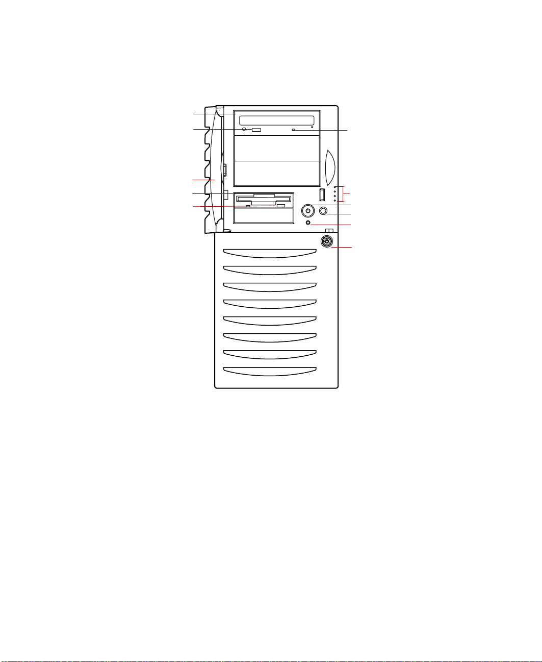
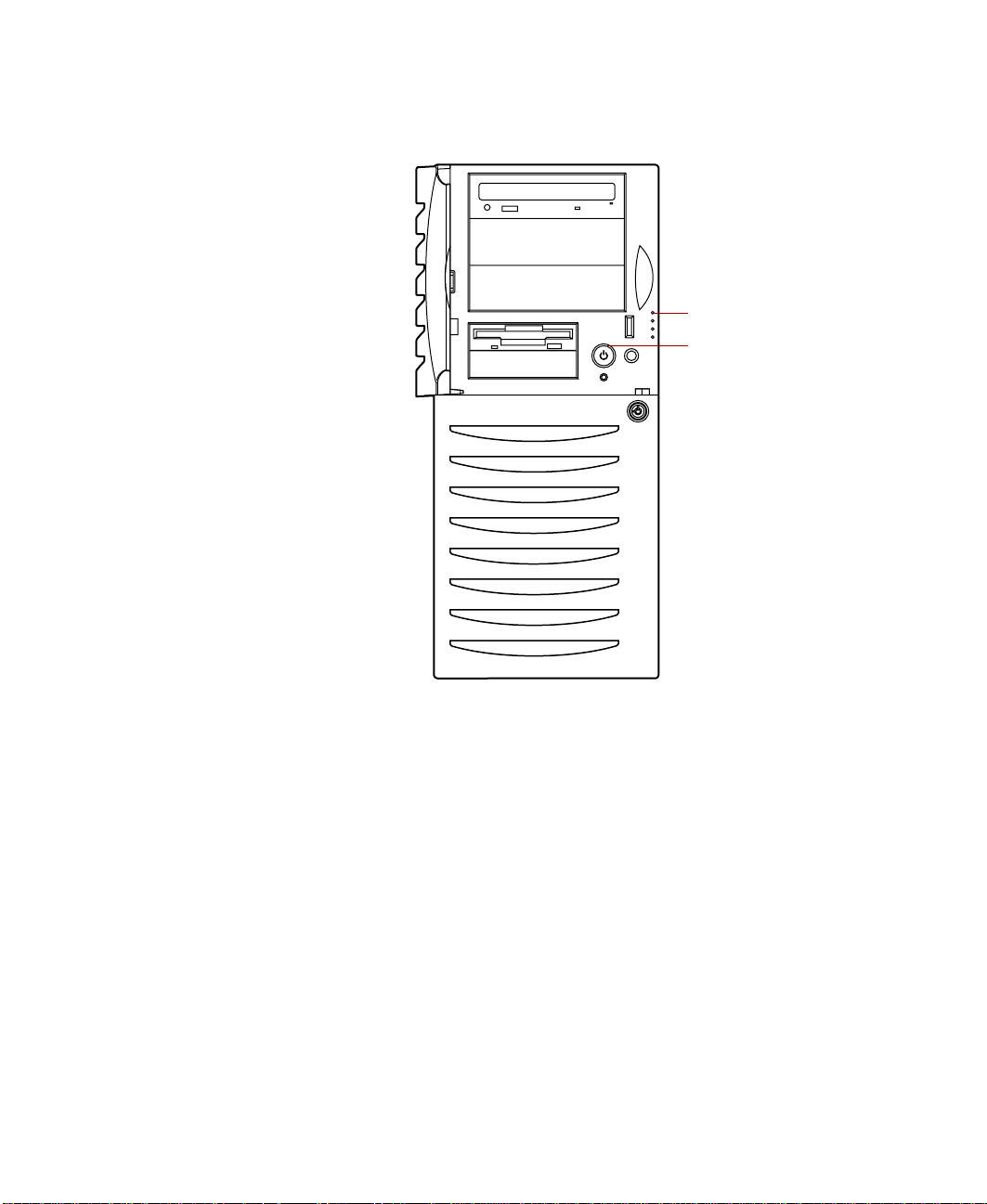
Front panel
CD drive
CD eject
button
Door (open)
Diskette drive
Diskette
eject button
CD activity LED
Front panel LEDs
Power button
Reset button
System fault LED
reset switch
Door lock
CD activity LED, when lit, indicates the drive is active.
CD drive plays data or audio CDs.
CD eject button ejects a CD from the CD drive.
Diskette drive writes to and reads from 3.5-inch, 1.44 MB diskettes.
Diskette eject button ejects diskettes from the diskette drive.
Door protects the external controls of the computer and the externally
accessible drives.
Door Lock controls access to the external controls and externally accessible
drives.
2 System Features
Page 12

Front panel LEDs indicate the following when lit:
■ Power On LED (steady green indicates power is on and blinking green
indicates system is in sleep mode).
■ HDD Activity LED (green) indicates when hard drive is active.
■ NIC Activity LED (green) indicates LAN activity.
■ System Fault LED (yellow) indicates ECC (Error Checking and
Correcting) memory system fault (steady indicates an uncorrectable ECC
fault and blinking indicates a correctable ECC fault).
System Fault LED reset switch is used to clear system fault LED.
Power button turns the computer on and off. It also enables sleep-mode in
some operating systems.
Reset button restarts the system when it becomes non-responsive.
Front panel 3
Page 13
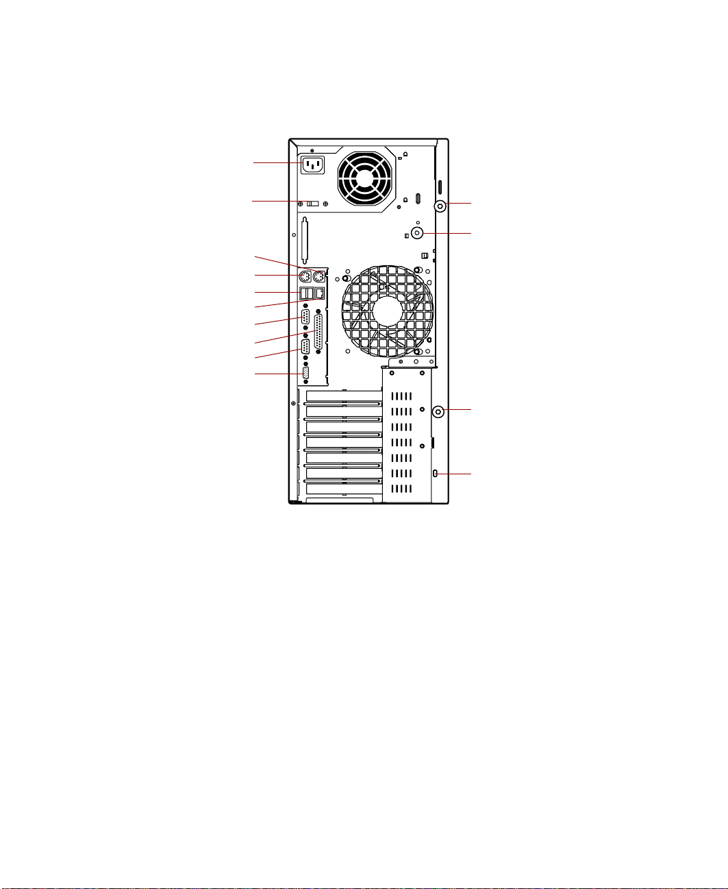
Rear panel
Power connector
Voltage selector
Mouse port
Keyboard port
USB ports
RJ-45 LAN port
Serial port A
Parallel port
Serial port B
Video port
Thumbscrew
Chassis lock
Thumbscrew
Kensington
lock slot
Chassis lock locks the side cover to secure the interior of the system.
Kensington lock slot lets you use a cable lock to secure the system.
Keyboard port connects a PS/2-compatible keyboard.
Mouse port connects a PS/2-compatible mouse.
Parallel (printer) port connects a printer or other parallel device.
Power connector connects the computer power cord. The other end of the
power cord plugs into an AC outlet or power strip.
RJ-45 LAN port connects to an ethernet network.
Serial ports connect to serial devices.
4 System Features
Page 14

Thumbscrews must be loosened to remove the cover from the system.
USB ports connect external Plug-and-Play devices that are automatically
configured when they are plugged into the computer through one of these
ports. USB keyboards and mice are not supported, use only PS/2 versions.
Video port connects the monitor interface cable.
Voltage selector sets the voltage for your area, either 115 V or 230 V.
Rear panel 5
Page 15
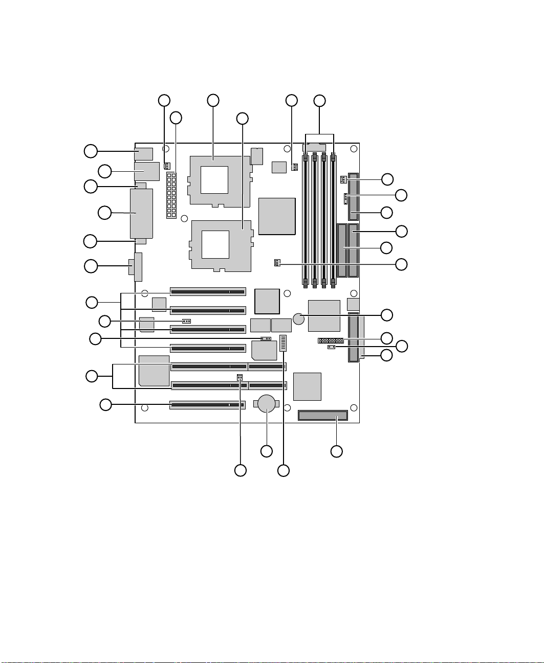
System board
AE
AC
AA
A
B
AD
AB
Z
Y
X
W
V
C
D
E
F
G
H
I
J
K
L
M
N
O
P
U
A Rear Chassis Fan connector
B Main ATX power connector
C CPU 1 socket
D CPU 2 socket
E CPU 1 fan connector
6 System Features
S
T
R
Q
Page 16

DIMM sockets (0 to 3, left to right)
F
G Front chassis fan connector
2
H I
C SMB header
I Floppy drive connector
J Primary IDE connector
K Secondary IDE connector
L CPU 2 fan connector
M Speaker
N Front panel connector
O Auxiliary HDD activity LED connector
P Ultra160 LVD SCSI Channel A connector
Q Ultra160 LVD SCSI Channel B connector
R Configuration switch
S Battery
T (not used)
U PCI 32-bit/33 MHz slot
V PCI 64-bit/33 MHz slots (2)
W (not used)
X (not used)
Y PCI 32-bit/33 MHz slots (4)
Z Video port
AA Serial port B
AB Parallel port
AC Serial port A
AD RJ-45 Ethernet port and USB ports 1 and 2
AE Keyboard port and PS/2 Mouse port
System board 7
Page 17

8 System Features
Page 18

System Setup
Setting up your system
Use the instructions on the Quick Guide poster that came with your system
to assemble your system.
You can prepare a safer working environment before assembling your system
by following these guidelines:
■ Use a clean, flat, and stable surface for your system. Allow at least
12 inches at the rear of the computer for cabling and air circulation.
■ Obtain a grounded (three-prong) AC surge-protected power strip. A
surge-protected power strip helps protect against AC power fluctuations.
■ Protect your system from extreme temperature and humidity. Do not
expose your system to direct sunlight, heater ducts, or other
heat-generating objects.
■ Keep your computer away from equipment that generates magnetic
fields, such as unshielded stereo speakers. Even a telephone placed too
close to the computer may cause interference.
2
■ Plug the computer into a wall outlet or power strip that is easily
accessible.
Important Keep the computer boxes and packing material in case
you need to send the computer to Gateway for repairs. If
you return your computer in different packaging, your
warranty may be voided.
Setting up your system 9
Page 19

Starting your system
Before you start your system for the first time:
■ Make sure that the voltage selector switch on the back of the computer
is set to the correct voltage for your area. This switch is set at the factory
to the correct voltage (see “Rear panel” on page 4 for the voltage selector
switch location).
■ Make sure all cables are firmly connected to the proper ports on the rear
panel of the computer.
Caution Make sure your computer and peripherals are turned off
and unplugged from the power outlet when you connect
peripherals to the computer, o r you might damage the
computer or the peripherals.
■ Make sure the computer and monitor are plugged into an AC outlet or
power strip and that the power strip is turned on.
To start the system:
1 If you have connected the system components to a power strip, make
sure all the system components are turned off, then turn on the power
strip.
2 Turn on the monitor.
10 System Setup
Page 20
Turn on the computer. The top light-emitting diode (LED) at the right
3
side of the bezel is lit when the power is on.
Power LED
Power button
4 Turn on any other components connected to the computer, such as
speakers, a printer, or a scanner.
If nothing happens when you turn on the system:
■ Make sure that the power cables are securely plugged in and that
your power strip (if you are using one) is plugged in and turned on.
■ Make sure the monitor is connected to the computer, plugged into
the power strip or AC outlet, and turned on. You may also need
to adjust the brightness and contrast controls on the monitor.
Starting your system 11
Page 21

Understanding the Power-OnSelf-Test
When you turn on your computer, the power-on self-test (POST) routine
checks the system memory and components. To see this information on the
screen, press T
The system displays error messages if POST finds any problems. Write down
any error messages that you see. If you continue to have problems, these error
messages may help technical support diagnose the cause.
AB during POST.
Setting up the operating system
The first time you start your computer, the operating system takes a few
minutes to set up.
Refer to your operating system documentation for specific questions regarding
the operating system.
To complete the operating system setup for Windows NT:
1 After the computer starts, the start-up wizard opens. Continue by clicking
Next.
2 Type the requested information in the appropriate text boxes. When you
have finished typing the information, continue by clicking
Next.
3 Continue following the instructions and selecting options in the start-up
wizard dialog boxes, clicking
the wizard tells you to restart your computer.
If you need to return to the previous dialog box to change any of your
entries, click
4 Restart your system. The setup is complete.
Important For other operating systems, such as Windows®2000 or
12 System Setup
Next to move through the dialog boxes, until
Back.
®
Novell
system software manual for setup instructions.
NetWare, refer to the appropriate operating
Page 22

Turning off your system
Every time you turn off your system, shut down the operating system first.
You may lose data if you do not follow the proper procedure.
To turn off your system in Windows NT:
1 Click Start, then select Shut down the computer?, then Shut Down.
2 Click OK. The computer turns off. If you see a message saying It is now
safe to turn off your computer
button.
3 Turn off the monitor and peripherals.
Warning When you turn the computer off by pressing the power
button, some electric current still flows through the
computer. Before opening the computer case or
connecting or removing any peripherals, turn off the
computer, then unplug the power cord and modem cord
(if installed) or you may get an electric shock.
, turn off the computer by pressing the power
Important For other operating systems, such as Windows®2000 or
®
Novell
system software manual for instructions.
NetWare, refer to the appropriate operating
Turning off your system 13
Page 23

Resetting your system
If your computer does not respond to keyboard or mouse input, you may have
to close programs that are not responding. If closing unresponsive programs
does not restore your computer to normal operation, you may have to reset
the system.
To close unresponsive programs and reset your system in Windows NT:
1 Press CTRL+ALT+DEL. A window opens that lets you to close a program
that is not responding.
2 Click Task Manager, then select the program that is not responding.
3 Close the program by clicking End Task.
4 If the computer does not respond, press the reset button to restart the
computer.
As a part of the regular startup process, a program to check the disk status
runs automatically. When the checks are finished, Windows starts.
Important For other operating systems, such as Windows 2000 or
Novell NetWare, refer to the appropriate operating system
software manual for instructions.
14 System Setup
Page 24

Case Access
3
Preventing static electricity discharge
Before opening the computer case, follow these precautions to prevent
damage from static electricity. When opening your computer case, always
perform the following procedure.
Caution Static electricity can permanently damage electronic
components in your computer. Prevent electrostatic
damage to your computer by following static electricity
precautions every time you open your computer case.
To prevent static electricity discharge:
1 Wear a grounding wrist strap (available at most electronics stores).
2 Turn off the computer power.
3 Touch a bare metal surface on the back of the computer.
4 Unplug all power cords from AC outlets and disconnect the modem cable
(if installed).
Preventing static electricity discharge 15
Page 25

Also follow these static electricity precautions:
■ Avoid static-causing surfaces such as plastic and packing foam in your
work area.
■ Remove the parts from their antistatic bags or containers only when you
are ready to use them. Do not lay parts on the outside of an antistatic
bag or container because only the inside provides antistatic protection.
■ Always hold cards by their edges and their metal mounting brackets.
Avoid touching components on the cards and the edge connectors that
connect to expansion slots. Never slide cards or other parts over any
surface.
16 Case Access
Page 26

Opening the case
Important All references to front, rear, left, or right on the computer
are based on the computer being in a normal, upright
position, as viewed from the front.
To work on the internal components of the computer, you must open the
case, which has two removable parts:
■ A left side cover panel that permits access to the interior of the case
■ A bezel that covers the front of the chassis
Because the components inside your computer are extremely sensitive to static
electricity, make sure to follow the precautions at the beginning of this chapter
for avoiding static electricity damage.
Only qualified personnel should open the system for maintenance. If you are
qualified to maintain the system yourself, make sure you are properly
grounded before opening the system chassis.
Warning Avoid exposure to dangerous electrical voltages and
movingparts byturning off your computerand unplugging
the power cord and modem cable (if installed) before
removing the chassis cover.
Opening the case 17
Page 27
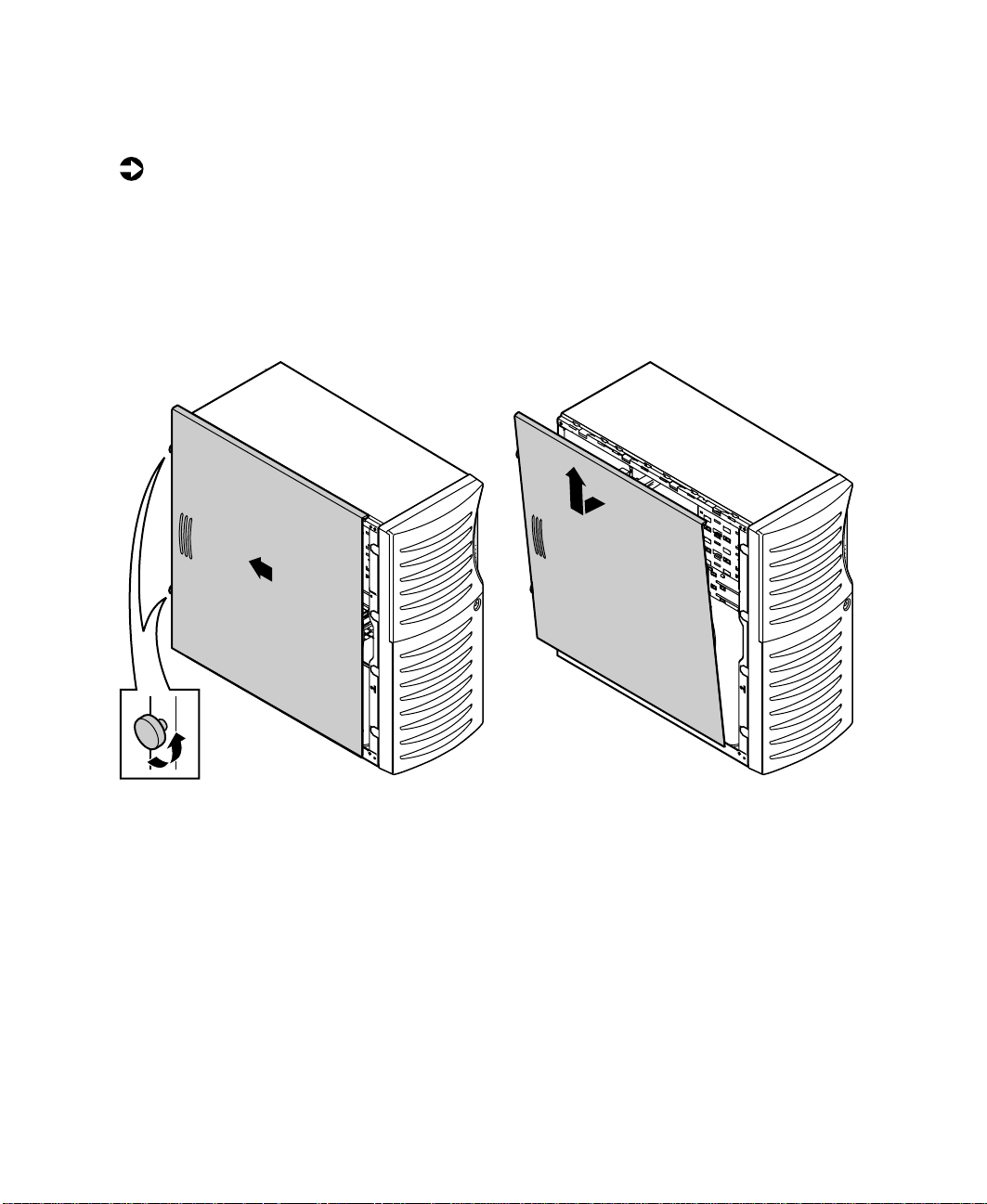
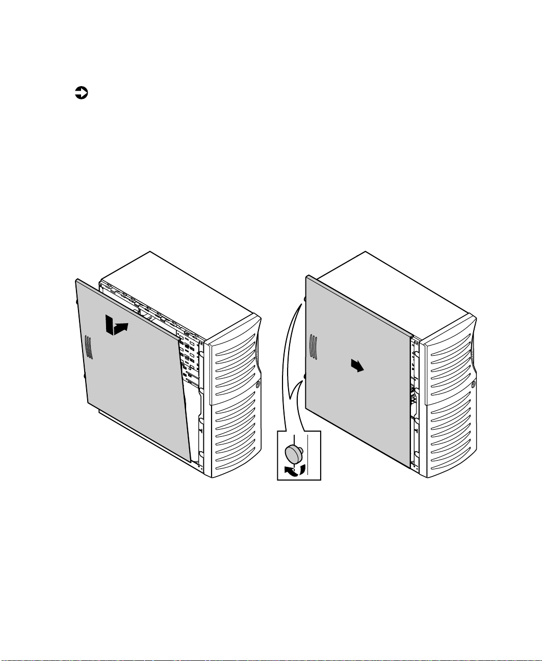
Removing the side cover
To remove the left side cover panel:
1 Turn off the computer and disconnect all power cords.
2 Loosen the thumbscrews (captive) on the back of the side panel and
unlock the chassis lock (if applicable).
3 Slide the left side panel to the rear (approximately 3/4-inch), disengaging
the retaining tabs on the top edge of the panel from the top of the chassis.
4 Tilt the panel out, then lift it up and away from the chassis.
18 Case Access
Page 28
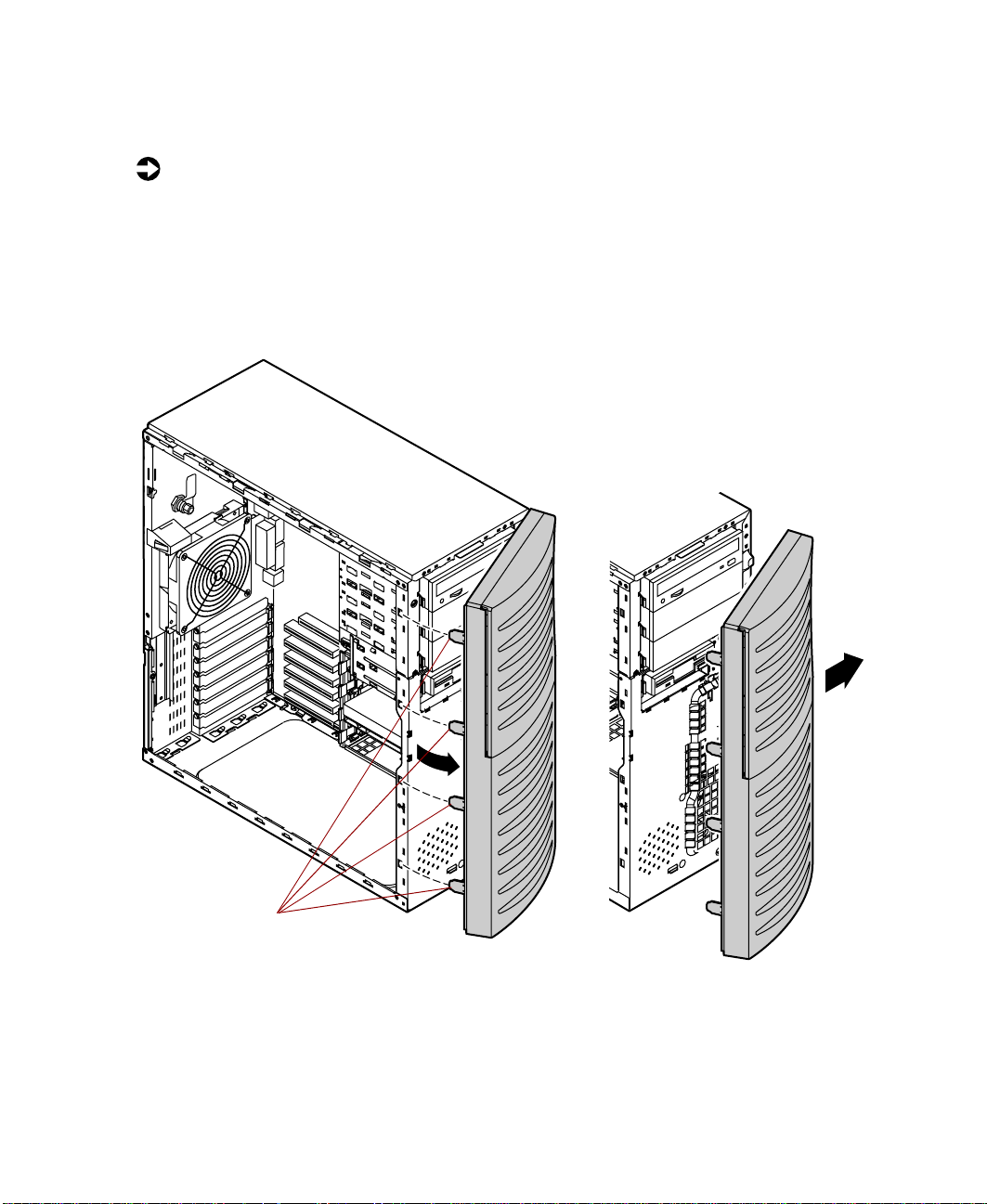
Removing the bezel
To remove the bezel:
1 With the left side panel removed, disengage the retention tabs on the
left side of the bezel by prying outward on each tab.
2 Swing the bezel out from the front of the chassis and disengage the hinge
tabs on the right side of the bezel by moving the bezel to the right.
3 Remove the bezel.
Retention tabs
Opening the case 19
Page 29
Closing the case
Replace the chassis cover as soon as you finish installing or removing
components so that dust and dirt do not collect inside the computer.
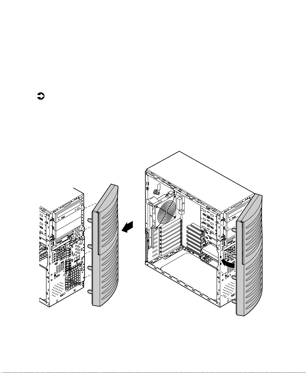
Replacing the bezel
To replace the bezel:
1 Holding the bezel at an angle to the front of the chassis, place the hinge
tabs on the right side of the bezel in the appropriate slots in the front
of the chassis.
2 Swing the left side of the bezel toward the chassis until the retaining tabs
snap into place.
Four hinge tabs are located
on the right side of the bezel
and are not visible in this
illustration.
20 Case Access
Page 30
Replacing the side cover
To replace the chassis cover:
1 Hold the left side panel at an angle to the chassis and 3/4-inch to the rear.
2 Engage the retaining strip on the bottom edge of the panel with the lip
at the bottom edge of the chassis.
3 Swing the top of the panel toward the chassis, engaging the retaining
tabs on the top edge of the side panel with the slots on the chassis.
4 Slide the panel toward the front of the chassis 3/4-inch, securing it in
place.
5 Retighten the thumbscrews and lock the case, if necessary.
Closing the case 21
Page 31

22 Case Access
Page 32

Replacing and Adding System Components
Replacing or adding drives
Preparingto replaceor add a drive
One 3.5-inch diskette drive, one 3.5-inch hard drive, and one CD drive are
included with your computer. You can add additional drives of the following
types:
■ Half-height 3.5-inch diskette drives - The floppy controller supports one
diskette drive.
■ Half-height 3.5-inch hard drives - The standard integrated Symbios
2-channel SCSI controller will support as many as 30 drives.
■ Half-height 3.5-inch tape storage or disk storage devices.
■ Half-height 5.25-inch devices.
4
Replacing or adding drives 23
Page 33

5.25-inch drive cage
Middle 3.5-inch
drive cage
Bottom 3.5-inch
hard drive cage
As you prepare to install drives, keep the following in mind:
■ To remove and install drives, you need an antistatic wrist strap.
■ If you remove a drive, place it in an antistatic bag or container.
■ Before you install a drive, see the drive documentation for information
on configuring the drive, setting any jumpers on the drive, and attaching
cables to the drive.
■ If you are installing a drive that requires a controller card, install the card
before you install the drive.
■ IDE hard drives can be configured as single, master, or slave. IDE CD
drives can be configured as master or slave. Configure the drives by using
the drive-select jumpers located on the drives.
■ If only one drive is attached to a controller cable, configure the drive as
single if it is a hard drive or master if it is a CD drive. If two drives of
any type are attached to the cable, configure one as master and one as
slave.
■ You may need to configure the drives you install using the BIOS Setup
utility. Press F1 at start up to open the BIOS Setup utility.
24 Replacing and Adding System Components
Page 34

Drive cabling information
Your system includes three different types of drive cables. Each drive cable is
clearly labeled, indicating cable-type and showing which end is connected to
the appropriate connector on the system board and which end is connected
to the drive.
Use the diskette drive connector cable to connect the diskette drive. Use the
standard IDE connector cable to connect IDE devices such as CD drives and
standard IDE hard drives. Use the SCSI LVD cable to connect LVD-compatible
SCSI devices. A terminator comes installed on this cable.
You can also obtain two optional cables for your system. The IDE DMA-66
cable is used to connect DMA-66-compatible hard drives, and the SCSI SE cable
is used to connect single-ended SCSI devices and requires termination, either
on the device or as a plug-in terminator on the cable.
3.5-inch diskette or CD drives
Both the 3.5-inch diskette drive and 5.25-inch CD drives are secured in the
chassis by removable rails. The rails let the drives slide into and out of the
guides in the front bays. Extra rails are included with your system and are
clipped to the outsides of the drive cages, inside the case.
Replacing the 3.5-inch diskette or CD drive
To replace the drives:
1 Turn off the system and disconnect the power cord, modem cord (if
installed), and all external peripheral devices.
2 Remove the left side cover panel. (See “Removing the side cover” on
page 18 and “Preventing static electricity discharge” on page 15.)
3 Remove the bezel. (See “To remove the bezel:” on page 19.)
4 Locate the 3.5-inch diskette or 5.25-inch CD drive you want to replace.
5 Remove the power and data cables from the back of the drive, noting
their locations and orientations. (You will reconnect these cables after you
install the new drive.)
Replacing or adding drives 25
Page 35

6 Disengage the rail locking tabs by pressing inward on both front rail
extensions, then move the drive slightly out of the bay by pushing on
the back of the drive. Pull the drive out of the chassis.
7 Remove the rails on both sides of the drive and snap them onto the new
drive in the same positions. Make sure the front rail extensions are
towards the front of the drive.
Important The rails on the 3.5-inch drive are different from those on
the CD drive. Make sure you install the correct rails on
each drive.
CD drive
R
3.5-inch
diskette drive
L
8 Set the drive jumpers to the appropriate settings (refer to your drive
documentation for jumper settings).
9 Align the rails with the appropriate open bay, then slide the drive into
the bay until the locking tabs snap into place.
10 Connect the power and data cables, making sure the cables are in their
original positions.
11 Close the case by following the instructions on page 20.
12 Reconnect peripherals, the modem cord, and the power cord, then turn
on the system.
26 Replacing and Adding System Components
Page 36

Adding a 3.5-inch device
You can use the second, externally accessible, 3.5-inch drive bay to install a
3.5-inch device such as a tape drive or a 100 MB or 120 MB disk storage device.
Extra sets of rails are included with your system (clipped to the drive cage)
and are used for the installation.
You may have to purchase an additional cable with three connectors and of
sufficient length to connect the existing devices and the new device to the
connector on the system board.
To install an additional device in the 3.5-inch drive bay:
1 Turn off the system and disconnect the power cord, modem cord (if
installed), and all external peripheral devices.
2 Remove the left side cover panel. (See “Removing the side cover” on
page 18 and “Preventing static electricity discharge” on page 15.)
3 Remove the bezel. (See “To remove the bezel” on page 19.)
4 Remove the plastic bezel insert covering the open bay by disengaging the
retaining tab and pushing the insert out from the back of the bezel. Save
the insert so that you can replace it if you remove the added device.
Replacing or adding drives 27
Page 37

5 Remove the metal EMI shield from the front of the drive bay, if installed,
by unscrewing the retaining screw on the right side of the shield and
swinging it out to disengage it from the chassis.
Metal EMI
shield
Remove screw
Caution Your system was designed to adhere to electromagnetic
interferencerequirementsandthe shieldisan integralpart
of the system. Installing an approved device should
continue to maintain those standards. If you remove the
device you should reinstall the shield.
6 Snap the rails onto the drive, making sure the front rail extensions are
towards the front of the device.
28 Replacing and Adding System Components
Page 38

Set the drive jumpers to the appropriate settings (refer to your drive
7
documentation for jumper settings).
8 Align the rails with the open bay, then slide the drive into the chassis
until the locking tabs snap into place.
9 Connect the power and data cables to the back of the drive.
10 Close the case by following the instructions on page 20.
11 Reconnect peripherals, the modem cord, and the power cord, then turn
on the system.
12 Run the configuration software, if necessary.
Replacing or adding drives 29
Page 39

Adding a 5.25-inchdevice
You can install additional 5.25-inch devices such as a CD-RW drive or a tape
backup in the two other, externally accessible, 5.25-inch drive bays. An extra
set of rails is included with your system (clipped to the drive cage) and is used
for the installation.
You may need to purchase an additional cable of sufficient length to connect
the existing devices and the new device to the connector on the system board.
To install an additional device in the 5.25-inch drive bay:
1 Turn off the system and disconnect the power cord, modem cord (if
installed), and all external peripheral devices.
2 Remove the left side cover panel. (See “Removing the side cover” on
page 18 and “Preventing static electricity discharge” on page 15.)
3 Remove the bezel. (See “To remove the bezel” on page 19.)
4 Remove the plastic bezel insert covering the open bay by disengaging the
retaining tab and pushing the insert out from the back of the bezel.
30 Replacing and Adding System Components
Page 40

Remove the metal EMI shield from the front of the drive bay, if installed,
5
by placing a finger in the hole on the left side of the shield and pulling
out to disengage it from the chassis.
Caution Your system was designed to adhere to electromagnetic
interferencerequirementsandthe shieldisan integralpart
of the system. Installing an approved device should
continue to maintain those standards. If you remove the
device you should reinstall the shield.
Metal EMI
shield
Pull out on the
left side of the
metal EMI shield
6 Snap the rails onto the drive, making sure the front rail extensions are
to the front of the device.
Replacing or adding drives 31
Page 41

7 Set the drive jumpers to the appropriate settings (refer to your drive
documentation for jumper settings).
8 Align the rails with the bay, then slide the drive into the chassis until
the locking tabs snap into place.
9 Connect the power and data cables, making sure the cables match their
original position.
10 Close the case by following the instructions on page 20.
11 Reconnect peripherals, the modem cord, and the power cord, then turn
on the system.
12 Run the configuration software, if necessary.
32 Replacing and Adding System Components
Page 42

Harddrive
Replacing the hard drive
To replace the hard drive:
1 Turn off the system and disconnect the power cord, modem cord (if
installed), and all external peripheral devices.
2 Remove the left side cover panel. (See “Removing the side cover” on
page 18 and “Preventing static electricity discharge” on page 15.)
3 Locate the 3.5-inch hard drive in the bottom drive cage.
4 Remove the power and data cables from the back of the drive, noting
their locations and orientations. (You will reconnect these cables after you
install the new drive.)
5 Grip the plastic mounting rails firmly with thumb and index finger and
pull the drive carefully straight out of the drive cage.
6 Remove the small plastic mounting rails from the hard drive.
Replacing or adding drives 33
Page 43

7 Place the old drive in an antistatic bag or container, then place the new
hard drive on a static-free surface with the top up and the connectors
facing you.
8 Install two small, plastic drive mounting rails (L rail on the left and R rail
on the right) to the new hard drive. Make sure the front rail extensions
are towards the connector end of the device. Align the wire retention clips
to the mounting holes in the drive and press the rails to the sides of the
drive.
Rrail
R
Lrail
9 Set the drive jumpers to the appropriate settings (refer to your drive
documentation for jumper settings).
10 Align the rails with an open bay in the bottom drive cage, and slide the
drive into the cage until the locking tabs snap into place. Be sure that
the data and power connectors on the drive face out.
11 Connect the power and data cables to the drive.
12 Close the case by following the instructions on page 20.
13 Reconnect peripherals, the modem cord, and the power cord, then turn
on the system.
Adding a harddrive
The system comes equipped with a drive cage that will accept additional hard
drives. You may have to purchase an additional data cable with three
connectors and of sufficient length to connect the existing hard drive and
the new drive to the appropriate drive controller connector (IDE or SCSI) on
the system board.
L
34 Replacing and Adding System Components
Page 44

If you purchase an additional hard drive from Gateway, you will receive drive
rails that you use to install the new drive in the drive cage. Additional drive
rail kits are also available.
To install an additional hard drive:
1 Turn off the system and disconnect the power cord, modem cord (if
installed), and all external peripheral devices.
2 Remove the left side cover panel. (See “Removing the side cover” on
page 18 and “Preventing static electricity discharge” on page 15.)
3 Place the new hard drive on a static-free surface with the top up and the
connectors facing you.
4 Check the jumper settings on the drive. (See drive documentation for
jumper settings.)
5 Install the two small, plastic drive mounting rails (L rail on the left and
R rail on the right) to the new hard drive. Make sure the front rail
extensions are towards the connector end of the device. Align the wire
retention clips to the mounting holes in the drive and press the rails to
the sides of the drive.
Replacing or adding drives 35
Page 45

6 Align the rails with an open bay in the bottom drive cage, and slide the
drive into the chassis until the locking tabs snap into place.
7 Connect the data and power cables to the drive. (See drive documentation
for proper cable orientation.)
8 Close the case by following the instructions on page 20.
9 Reconnect peripherals, the modem cord, and the power cord, then turn
on the system.
36 Replacing and Adding System Components
Page 46

Replacing or adding memory
The Synchronous Dynamic Random Access Memory (SDRAM) Dual Inline
Memory Modules (DIMMs) supported by your system board conform to the
following standards:
■ 64 MB, 128 MB, 256 MB, and 512 MB DIMMs.
■ PC133-compliant, registered, parity, ECC SDRAM.
Memory is installed in four banks (slots) on the system board. When you are
selecting and installing DIMMs, keep the following in mind:
■ Registered DIMMs should not be combined with unbuffered DIMMs.
■ No jumper settings are required for the memory size or type because the
BIOS automatically detects this information.
■ 2 GB maximum system memory.
To replace DIMMs:
1 Turn off the system and disconnect the power cord, modem cord (if
installed), and all external peripheral devices.
2 Remove the left side cover panel. (See “Removing the side cover” on
page 18 and “Preventing static electricity discharge” on page 15.)
3 Pull open the socket latches on each side of the DIMM socket, then lift
the DIMM out of the socket. Store the DIMM in an antistatic container.
Replacing or adding memory 37
Page 47

4 Insert the new DIMM into the socket and align the two notches in the
DIMM with the two notches in the DIMM socket.
5 Gently press the DIMM into the socket until it is firmly seated. Inserting
the DIMM automatically locks the socket latches on each end of the
DIMM.
6 Close the case by following the instructions on page 20.
7 Reconnect peripherals, the modem cord, and the power cord, then turn
on the system.
To add or remove DIMMs:
1 Turn off the system and disconnect the power cord, modem cord (if
installed), and all external peripheral devices.
2 Remove the left side cover panel. (See “Removing the side cover” on
page 18 and “Preventing static electricity discharge” on page 15.)
3 If you are removing a DIMM, pull open the socket latches on each side
of the DIMM socket, then lift the DIMM out of the socket. Store the
DIMM in an antistatic container.
38 Replacing and Adding System Components
Page 48

If you are adding a DIMM, pull open the socket latches on each side of
4
the DIMM socket.
5 Insert the new DIMM into the socket and align the two notches in the
DIMM with the two notches in the DIMM socket.
6 Gently press the DIMM into the socket until it’s firmly seated. Inserting
the DIMM automatically locks the socket latches on each end of the
DIMM.
7 Close the case by following the instructions on page 20.
8 Reconnect peripherals, the modem cord, and the power cord, then turn
on the system.
Replacing or adding memory 39
Page 49

Replacing or adding a processor
The system is compatible with the Pentium®III (FC-PGA Socket 370) 667 MHz
and faster processors with 133 MHz front-side bus (FSB). As many as two
processors may be installed in the system (they must have the same processor
and FSB speed). Processor and FSB speed are automatically detected by the
system, therefore there are no system board jumpers to set.
When adding or replacing a processor, order a processor upgrade kit from
Gateway. The kit includes the processor, a heatsink, and a disposable,
antistatic wriststrap. The kit also contains a copy of the muloader.exe
program, which must be run to update the microcode table and enable the
second processor. Voltage Regulator Modules (VRMs) for both processors are
built into the system board.
Caution A heatsink must be installed on each processor. Installing
a processor without a heatsink could result in damage to,
or failure of, the processor.
To replace the processor you must perform the following tasks:
■ Remove the heatsink
■ Remove the processor
■ Install the new processor
■ Replace the heatsink
To remove the heatsink:
1 Turn off the system and disconnect the power cord, modem cord (if
installed), and all external peripheral devices.
2 Remove the left side cover panel. (See “Removing the side cover” on
page 18 and “Preventing static electricity discharge” on page 15.)
3 Disconnect the fan cable from the fan connector on the system board.
(See “System board” on page 6 for the location of the fan connector.)
40 Replacing and Adding System Components
Page 50

Unhook the metal clip from the tab on the processor socket by pressing
4
down on the clip and then pulling out on the clip.
Metal clip
1.
2.
3.
Tabs
5 Unhook the other end of the metal clip.
6 Lift the heatsink straight up and off the processor.
Replacing or adding a processor 41
Page 51

To remove the processor:
1 Open the locking lever on the processor socket by moving the lever
slightly out to the side and then lifting it up 90 degrees.
Processor
Locking
lever
2 Lift the old processor straight up and out of the socket.
To install the new processor:
1 Hold the new processor over the empty processor socket and verify that
pin 1 on both the processor and the socket are aligned. Pin 1 is near the
marked corner of the processor.
2 Gently place the new processor into the socket, then secure the processor
by lowering the locking lever until the lever latches into place. The
processor will slip into place without pressure when aligned correctly.
Pin 1
42 Replacing and Adding System Components
Page 52

To replace the heatsink:
1 Hook the metal clip on the heatsink to the tabs on the processor socket.
Make sure the heatsink is level with the processor and the metal clips
are securely attached.
Caution It is very important that the heatsink makes direct contact
with the processor or it will not cool correctly, resulting in
processor failure.
1.
2.
3.
2 Connect the heatsink fan cable to the fan connector on the system board.
3 Close the case. (See “Closing the case” on page 20 for instructions.)
4 Reconnect the cords you removed, then turn on the computer.
Replacing or adding a processor 43
Page 53

To add an additional processor:
1 Turn off the system and disconnect the power cord, modem cord (if
installed), and all external peripheral devices.
2 Remove the left side cover panel. (See “Removing the side cover” on
page 18 and “Preventing static electricity discharge” on page 15.)
3 Hold the new processor over the empty processor socket and verify that
pin 1 on both the processor and the socket are aligned. Pin 1 is near the
marked corner.
4 Gently place the new processor into the socket.
5 Secure the processor by lowering the locking lever until the lever latches
into place. The processor will slip into place without pressure when
aligned correctly.
6 Install the heatsink. (See “To replace the heatsink:” on page 43.)
7 Connect the power supply cable of the processor fan to the second CPU
fan connector on the system board (See “System board” on page 6 for
location).
8 Close the case by following the instructions on page 20.
9 Reconnect the cords you removed, then turn on your computer.
10 Run the muloader.exe program that was included in the processor
upgrade kit in order to update the microcode table and enable the second
processor.
44 Replacing and Adding System Components
Page 54

Adding an expansion card
This server has seven PCI expansion slots on the system board that may be
used for a variety of expansion cards. These cards may include a SCSI
controller card, a modem, a high-end sound card, or an additional IDE
controller card.
To add an expansion card:
1 Set any jumpers and switches on the card, if required. (See the card
instructions.)
2 Turn off the computer, disconnect the power cord, modem cord (if
installed), and all external peripheral devices.
3 Remove the left side cover panel. (See “Removing the side cover” on
page 18 and “Preventing static electricity discharge” on page 15.)
4 Locate an available slot appropriate to the type of card you are installing,
and remove the slot cover by removing the screw that secures it to the
back of the chassis.
Adding an expansion card 45
Page 55

5 Insert the bottom edge of the expansion card (the keyed edge with the
contacts) into the slot on the system board and push in firmly to seat
the card.
Screw
6 After seating the card firmly, use the screw you removed to secure the
card to the rear of the chassis.
7 Connect cables to the card, if required.
8 Close the case by following the instructions on page 20.
9 Reconnect peripherals, the modem cord, and the power cord, then turn
on the system.
You may need to reconfigure your system after installing some expansion
cards. You may also need to install software that came with the card. Check
the card documentation for additional information.
46 Replacing and Adding System Components
Page 56

Replacing the battery
The battery provides power for the system real-time clock and CMOS memory,
which holds the system configuration information.
If your battery is failing you may notice your system clock slowing down and
giving you the incorrect time. If so, open the BIOS Setup utility and write
down all the values in the various menus before replacing the battery.
Replacing the battery resets the BIOS Setup utility to its default values.
Warning There is a danger of explosion if the battery is incorrectly
replaced. Replace the battery only with the same or
equivalent type recommended by the manufacturer.
Dispose of usedbatteriesaccording to the manufacturer’s
instructions.
Warnung Explosionsgefahr bel falsch eingebautter batterie.
Ersetzen der batterien nur mit batterien des gleichen typs
oder mit batterien vom hersteller empfohlenen typs.
Entsorgen gebrauchter batterien entsprechned
herstellerangaben.
Attention Il y a danger d’explosion s’il y a replacement incorrect de
la batterie.
Remplacer uniquement avec une batterie du même type
ou d’un type équivalent recommandé par le constructeur.
Mettre au rebut les batteries usagées conformément aux
instructions du fabricant.
To replace the battery:
1 Restart the computer and start the BIOS Setup utility by pressing F1 when
you are prompted to do so.
2 Write down the CMOS values from the Main, Advanced, Security, Server
Boot menus so you can reenter them after you replace the battery.
and
For more information about the BIOS Setup utility program, see “Using
the BIOS Setup Utility” on page 67.
3 Turn off the computer, disconnect the power cord, modem cord (if
installed), and all external peripheral devices.
Replacing the battery 47
Page 57

4 Remove the left side cover panel. (See “Removing the side cover” on
page 18 and “Preventing static electricity discharge” on page 15.)
5 Locate the battery on the system board (see “System board” on page 6).
The battery is circular and has the positive pole mark (+) on the top.
6 Using a small, flat-bladed screwdriver, carefully remove the battery from
its socket on the system board.
7 Press the new battery in the socket with the positive pole up. Be sure you
have pressed the battery down far enough for it to contact the base of
the socket (it should snap into place).
8 Close the case by following the instructions on page 20.
9 Reconnect peripherals, the modem cord, and the power cord, then turn
on the system.
10 If the CMOS data is not correct, change the information in the BIOS Setup
utility using the data you recorded in Step 2.
Troubleshooting the battery installation
If you have problems after installing the new battery, try each of the items
listed below:
■ Turn off the computer and make sure that all exterior cables are attached
and secured to the correct connectors.
■ Make sure that all power switches are on. If the computer is plugged into
a power strip or surge protector, make sure it is turned on also.
■ Enter the BIOS Setup utility and compare the settings on the screen with
your notes or the system hardware manuals. Correct any discrepancies.
48 Replacing and Adding System Components
Page 58

■ Turn off the computer, remove the cover, and make sure that all cables
inside the case are attached securely. Also, make sure that the colored
cable edges are aligned correctly and that the connectors do not miss any
pins. Disconnect and reconnect the cables. Close the case as described
on page 20, reconnect the modem and power cords, then turn on the
computer.
■ Turn off the computer, remove the cover and, if you have the proper test
equipment, make sure that the new battery has power. (Although
unlikely, your new battery may be defective.) Close the case as described
on page 20, reconnect the modem and power cords, then turn on the
computer.
Replacing the battery 49
Page 59

Replacing the system board
The system board is mounted on stand-off retention hooks on the right side
of the chassis. The board is secured by six screws, one on the back-right of
the chassis (outside), and five inside the chassis.
Important All references to front, rear, left, or right on the computer
are based on the computer being in a normal, upright
position, as viewed from the front.
To remove the system board:
1 Turn off the system and disconnect the power cord, modem cord (if
installed), and all external peripheral devices.
2 Remove the left side cover panel. (See “Removing the side cover” on
page 18 and “Preventing static electricity discharge” on page 15.)
3 Place the chassis gently on its right side.
4 Remove all expansion cards from the system board. (See “Adding an
expansion card” on page 45.)
5 Disconnect all cables from the system board, including the power cables
from the power supply. Note where the cables are connected.
6 Remove the retaining screws securing the board to the right side of the
chassis (inside the chassis).
System Board components
removed for
clarity
Rear
50 Replacing and Adding System Components
Remove retaining
screws from these
holes
Front
Page 60

Loosen the retaining screw at the right rear of the chassis.
7
8 Slide the system board toward the front of the chassis slightly, to
disengage it from the stand-off retention hooks, then remove it carefully.
Standoff
retention hook
System board
retaining screw
9 Remove the system board mounting bracket by removing the two screws
securing it to the system board (refer to the illustrations on page 52) and
place the board in an antistatic bag or container.
Replacing the system board 51
Page 61

To install the system board:
1 Install the system board mounting bracket on the rear edge of the system
board by fastening the mounting bracket to the system board with two
screws.
Mounting bracket
52 Replacing and Adding System Components
Page 62

Holding the system board by the top and bottom edges, place it in the
2
case by aligning the mounting holes on the board with the standoffs
(threaded) and standoff retention hooks on the right side of the case.
Carefully align the I/O panel on the rear of the board with the I/O plate
on the case.
Standoff
retention hook
System board
retaining screw
3 Holding the system board in place, tighten the retaining screw on the
right rear of the case.
4 Replace the retention screws previously removed from the system board,
then tighten the screws.
Replacing the system board 53
Page 63

5 Reinstall the expansion cards.
6 Close the case by following the instructions on page 20.
7 Reconnect peripherals, the modem cord, and the power cord, then turn
on the system.
54 Replacing and Adding System Components
Page 64

Replacing the power supply
To remove the power supply:
1 Turn off the system and disconnect the power cord, modem cord (if
installed), and all external peripheral devices.
2 Remove the left side cover panel. (See “Removing the side cover” on
page 18 and “Preventing static electricity discharge” on page 15.)
3 Lay the case on its right side, if possible.
4 Disconnect the power supply connectors from all internal devices
including the 3.5-inch diskette drive, the CD drive, and all hard drives.
5 Disconnect the main power supply connector to the system board by
pressing on the tab to release the connector, then gently pulling the
connector from the board.
6 Remove the cable supports securing the power supply cables to the
chassis.
Replacing the power supply 55
Page 65

7 Remove the two supporting screws securing the power supply to the top
of the chassis.
8 While supporting the power supply with one hand, remove the two
screws securing the power supply to the rear of the chassis, then carefully
lift the power supply out of the chassis.
Screws
To install the new power supply:
1 Before installing the new power supply, verify that it matches the one
you previously removed. The mounting holes should line up correctly,
and the specifications and power output connectors should be the same.
2 Make sure that the red voltage switch on the back of the new power
supply is set to the proper voltage for your area.
3 Place the new power supply in position in the chassis and line up the
mounting holes with the holes in the chassis. Note that alignment pins
in the chassis go into mounting holes in the rear of the power supply.
4 Replace the two screws securing the power supply to the back of the
chassis, leaving them slightly loose.
56 Replacing and Adding System Components
Screws
Page 66

Replace the two supporting screws securing the power supply to the top
5
of the chassis, then tighten all screws.
6 Reconnect the power connectors to the system board and to all internal
devices.
7 Place the case upright, then close the case by following the instructions
on page 20.
8 Reconnect peripherals, the modem cord, and the power cord, then turn
on the system.
Replacing the power supply 57
Page 67

Replacing the system fans
The front system fan is mounted on the front of the bottom drive cage. The
rear system fan is mounted on a fan mounting bracket attached to the rear
of the system.
To remove the front system fan:
1 Turn off the system and disconnect the power cord, modem cord (if
installed), and all external peripheral devices.
2 Remove the left side cover panel. (See “Removing the side cover” on
page 18 and “Preventing static electricity discharge” on page 15.)
3 Remove the bezel, as described in “To remove the bezel” on page 19.
4 Disconnect the front fan power cable from the system board.
5 Remove the power and data cables from any hard drives mounted in the
bottom drive cage.
6 Remove the drives from the bottom drive cage and place them in
anti-static bags or containers.
58 Replacing and Adding System Components
Page 68

Remove the plastic card guide attached to the bottom drive cage by
7
depressing the locking tabs (from the rear of the guide) and pivoting the
top of the guide toward the back of the system. (You may have to remove
one or more expansion cards from the system board.)
Tab
Replacing the system fans 59
Page 69

8 Remove the two screws securing the bottom drive cage to the front of
the chassis and the two screws securing it to the right side of the chassis.
9 Slide the bottom drive cage toward the left side of the chassis, then toward
the back, disengaging it from the middle drive cage and the chassis.
10 Carefully remove the bottom drive cage from the chassis.
11 Remove the four screws securing the front system fan to the bottom drive
cage, then lift the fan from the cage. Note the routing of the fan power
cable.
60 Replacing and Adding System Components
Page 70

To install the new front system fan:
1 Place the new front system fan into the recess in the front of the bottom
drive cage. Orient the fan with the label toward the inside of the chassis
(toward the system board) and the fan power cable to the right of the
drive cage.
2 Secure the fan to the drive cage with the four screws previously removed.
3 Place the bottom drive cage into the chassis under the middle drive cage
and slide it forward so that the support tabs on top of the bottom cage
engage the middle drive cage. Slide the bottom drive cage right to align
the screw holes with the holes on the front of the chassis.
4 Secure the drive cage with the four screws previously removed. Make sure
to correctly route the fan power cable.
5 Replace the plastic card guide and any expansion cards removed
previously.
6 Replace the hard drives into the bottom drive cage.
7 Reconnect the data and power cables on the hard drives.
8 Plug the fan power cable into the appropriate connector on the system
board.
9 Replace the bezel, then close the case by following the instructions on
page 20.
10 Reconnect peripherals, the modem cord, and the power cord, then turn
on the system.
Replacing the system fans 61
Page 71

To remove the rear system fan assembly:
1 Turn off the system and disconnect the power cord, modem cord (if
installed), and all external peripheral devices.
2 Remove the left side cover panel. (See “Removing the side cover” on
page 18 and “Preventing static electricity discharge” on page 15.)
3 Disconnect the rear fan power cable from the system board.
4 Move the two plastic release tabs on the left side of the fan bracket (inside
the chassis) toward the front of the chassis, then move the fan bracket
to the left and remove.
5 Carefully remove the fan and bracket from the chassis.
Release tabs
62 Replacing and Adding System Components
Page 72

To install the new rear system fan assembly:
1 Place the fan bracket unit into the chassis by engaging the four retaining
tabs with the holes in the back of the chassis and sliding the unit to the
right until the two locking pins click into place.
2 Plug the fan power cable into the appropriate connector on the system
board.
3 Close the case by following the instructions on page 20.
4 Reconnect peripherals, the modem cord, and the power cord, then turn
on the system.
Replacing the system fans 63
Page 73

Replacing the control/LED board
To remove the control/LED board:
1 Turn off the system and disconnect the power cord, modem cord (if
installed), and all external peripheral devices.
2 Remove the left side cover panel. (See “Removing the side cover” on
page 18 and “Preventing static electricity discharge” on page 15.)
3 Remove the bezel, as described in “To remove the bezel” on page 19.
4 Remove the system fault LED reset switch button cover.
64 Replacing and Adding System Components
Screw
System fault
LEDresetswitch
button cover
Page 74

After noting the position of the cable, disconnect the front panel cable
5
from the front panel connector on the system board (see “System board”
on page 6).
6 Remove the single screw securing the control/LED board to the chassis,
then disengage the alignment tabs from the chassis.
7 Remove the bottom drive cage. (See “To remove the front system fan:”
on page 58.)
8 Remove the control/LED board from the chassis.
To install the new control/LED board:
1 Plug the front panel cable into the front panel connector on the system
board (see “System board” on page 6).
2 Insert the alignment tabs of the control/LED board into the slots on the
front of the chassis, then replace the retaining screw.
3 Replace the system fault LED reset switch button cover.
4 Replace the bezel, then close the case by following the instructions on
page 20.
5 Reconnect peripherals, the modem cord, and the power cord, then turn
on the system.
Replacing the control/LED board 65
Page 75

66 Replacing and Adding System Components
Page 76

Using the BIOS Setup Utility
About the BIOS Setup utility
The computer’s BIOS has a built-in setup utility that lets you configure several
basic system characteristics. The settings are stored in battery-backed RAM and
are retained even when the power is off.
Open the BIOS Setup utility by restarting the computer, then pressing F1 when
the Gateway logo screen appears during startup. The Main BIOS Setup utility
screen opens. It may not look exactly like the screen shown below.
BIOS Setup Utility
Main Advanced Power Boot Security Exit
AMI BIOS Version :
BIOS Build Date :
BIOS ID :
Processor Type :
Processor Speed :
System Memory :
System Time :
System Date :
XX.XX.XX
XX/XX/XX
XXXXXXXX
Pentium III(tm)
800MHz
128 MB
[XX:XX:XX]
[Thu XX/XX/XXXX]
←→ Select Screen
↑ ↓ Select Item
-+ Change Field
Tab Select Field
F1 General Help
F10 Save & Exit
ESC Exit
5
About the BIOS Setup utility 67
Page 77

As you select items on the Main menu or in submenus, you see specific
information related to the current selection in the Item Specific Help box.
The command bar shows the keystrokes necessary to access help, navigate
through the menus, and perform other functions.
■ F1 opens the Help screen, providing general help for using the BIOS Setup
utility.
■ The ↑ (up arrow) and ↓ (down arrow) keys select items in the menu.
■ The ← (left arrow) and → (right arrow) keys move you between the
menus.
■ ENTER either moves you to a submenu screen when a selected item is
preceded by > or activates a selected field.
■ ESC closes the screen you are in and returns you to the previous screen
or opens a dialog box allowing you to exit from the BIOS Setup utility.
■ F10 opens a screen that lets you save all settings, then exit the BIOS Setup
utility.
The main screen has the following menu selections at the top of the screen:
■ Main gives you access to basic information and settings related to your
system hardware and configuration.
■ Advanced gives you access to information and settings for system
resources, hardware, and system configuration.
■ Power gives you access to information and settings for power
management features.
■ Boot gives you access to information and settings for boot features and
boot sequences.
■ Security gives you access to settings related to system access passwords
and security settings (See “System security” on page 79).
■ Exit gives you access to options for exiting the BIOS Setup utility.
Refer to the Help box on the right side of the BIOS Setup screens for
information about menu items.
68 Using the BIOS Setup Utility
Page 78

Updating the BIOS
If you need a new version of the BIOS, you can download the BIOS update
from technical support area on the Gateway Web site
(www.gatewayatwork.com) and install the new version from a diskette.
To update the BIOS you need to perform the following tasks in sequence:
■ Create a bootable diskette
■ Note the current BIOS settings
■ Create the BIOS update diskette
■ Update the BIOS
■ Restore the BIOS settings
Follow the detailed instructions for updating the BIOS that are included in
the self-extracting file that you can download from the technical support area
of Gateway’s Web site.
Important Whenever the BIOS is updated, the microcode table is
returned to the default setting. To update the table to the
proper settings for your processor, you must run the
MULOADER.EXE program, which is available from the
same site where you obtained the BIOS update files.
Updating the BIOS 69
Page 79

Setting the configuration switches
The system board has a configuration switch block related to the BIOS. You
can use specific switches to reset the CMOS settings to the BIOS defaults, or
to erase a misplaced or forgotten password. For the location of the
configuration switch block, see “System board” on page 6.
Caution Moving any of these switches while the power is on can
damage your computer. Always turn off the computer and
unplug thepower cordfromthe computer before changing
switch settings.
The Clear Passwor dswitch
The Clear Password switch on the system board (SW3) lets you clear the
existing system passwords in case they are misplaced or forgotten, or if the
system administrator is unavailable. For normal operation, SW3 should be set
to the OFF position. To clear the passwords, SW3 should be set to the ON
position. Make sure you turn off the computer and unplug the power cord
before moving the switch.
Once the switch is set to the ON position, passwords will be disabled, allowing
you to go directly to the operating system or to enter the BIOS Setup without
entering a password. To set up a new password, enter the BIOS Setup and enter
the password as you normally would, then turn off the system. Prior to turning
on the system again, open the case, return SW3 back to the OFF position,
then close the case.
The Clear CMOS switch
The Clear CMOS switch on the system board (SW4) lets you clear all BIOS
Setup settings. For normal operation, SW4 should be in the OFF position. To
clear the CMOS settings (and to clear passwords as well), SW4 should be
turned to the ON position. Make sure you turn off the computer and unplug
the power cord before moving the switch.
70 Using the BIOS Setup Utility
Page 80

Once the switch is set to the ON position, the system passwords will be cleared
when the system goes through the POST routine. When this occurs, the
following error message will appear:
CMOS checksum bad
Press F1 to run Setup
Press F2 to load default values and continue
After selecting the appropriate option, enter any required information and
continue. When you turn off the system again, open the case, set the switch
back to the OFF position, then close the case.
Setting the configuration switches 71
Page 81

72 Using the BIOS Setup Utility
Page 82

Managing Your System
Protecting againstpower source problems
Surge suppressors, line conditioners, and uninterruptible power supplies can
help protect your system against power source problems.
Surge suppressors
During a power surge, the voltage level of electricity coming into your system
can increase far above normal levels and cause data loss or system damage.
Protect your computer and peripherals by connecting them to a surge
suppressor, which will absorb voltage surges and prevent them from reaching
your computer.
When purchasing a surge suppressor:
■ Make sure the surge suppressor meets the appropriate product safety
certification for your location, such as Underwriters Laboratories (UL).
6
■ Check the maximum amount of voltage the suppressor allows to pass
through the line. The lower the voltage that the suppressor allows to pass
through, the better the protection for your system.
Protecting against power source problems 73
Page 83

■ Check the energy absorption (dissipation) rating. The higher the energy
absorption rating, the better the protection for your system.
■ Check for line-conditioner capabilities. A line conditioner smooths out
some of the normal line noise (small voltage fluctuations) of an electrical
supply.
Line conditioners
A line conditioner protects your system from the small fluctuations in voltage
from an electrical supply. Most systems can handle this variation, called line
noise, without problems. However, some electrical sources include more line
noise than normal. Line noise can also be a problem if your system is located
near, or shares a circuit with, a device that causes electromagnetic interference,
such as a television or a motor.
Some surge suppressors and uninterruptible power supplies include simple
line-conditioning capabilities.
Uninterruptible power supplies
Use a standby uninterruptible power supply (UPS) to protect your computer
from data loss during a total power failure. A UPS uses a battery to keep your
computer running temporarily during a power failure and lets you save your
work and shut down your computer. You cannot run your computer for an
extended period of time while using only the UPS.
74 Managing Your System
Page 84

Maintaining and managing your
hard drive
Regular maintenance can keep your hard drive operating efficiently and good
file management can keep your system free of unwanted files while making
important files secure and easier to find.
Hard drive maintenance utility
If you are using the Windows NT operating system, you can help maintain
the performance of your hard drive by regularly using Check Disk. If you are
using another operating system, refer to your operating system
documentation for available hard drive maintenance utilities.
Using Check Disk in Windows NT
Bad sectors are parts of a hard drive or diskette that will not hold data. A lost
allocation unit is a group of sectors that has lost its place in the table that
the operating system uses to locate files. Check Disk checks the hard drive
for bad sectors or lost allocation units and lets you fix them.
Use Check Disk from once a week to once a month, depending on how often
you use your system. Also use Check Disk if you have any hard drive problems.
To use Check Disk:
1 Double-click the My Computer icon. The My Computer window opens.
2 Right-click the drive you want to check.
3 Select Properties. The drive’s properties window opens.
4 Click the Tools tab.
5 At Error-checking, click Check Now. The Check Disk window opens.
6 Scan the entire hard drive by selecting Scan for and attempt recovery of bad
sectors
7 Click Start. Check Disk checks the drive for errors.
8 Follow any on-screen instructions for completing the scan.
.
Maintaining and managing your hard drive 75
Page 85

Hard drive management practices
By deleting unneeded files from your hard drive and managing the space that
is automatically allocated for saving certain files, you can help maintain the
performance of the hard drive. We suggest that you first check your hard drive
for available space, then back up important files prior to deleting unneeded
files, in case you delete important files by mistake.
Checkinghard drive space
In Windows NT, you can see a chart of the available hard drive space. If you
are using another operating system, refer to your software documentation for
available hard drive management utilities.
To check hard drive space:
1 Double-click the My Computer icon on the desktop. The My Computer
window opens.
2 Right-click the drive you want to check.
3 Select Properties. The drive’s properties window opens. The General tab
shows you the available and used space on the drive.
Backingupfiles
Regularly backing up your files protects you from losing data and lets you
keep fewer files on your hard drive. Back up old files to a large capacity disk
drive or tape drive and delete the files from your hard drive. You can use the
software that came with your tape backup drive or your large capacity disk
drive to back up the files.
You can also back up files by running the Backup utility that came with your
operating system. In Windows NT, Backup copies files to a tape drive.
To run Backup in Windows NT:
1 Click Start, then select Programs, Administrative Tools, then Backup.
2 Follow the on-screen instructions.
Deleting unneeded files
By deleting unneeded files from the hard drive, you free up space on the hard
drive and help improve hard-drive performance. The following sections give
you some simple ways to delete unneeded files.
76 Managing Your System
Page 86

Deleting Windows temporary files
During normal operation, Windows constantly creates new temporary (.tmp)
files. You can safely delete all but the most recent .tmp files.
To delete .tmp files:
1 Open Windows Explorer, then select Tools, Find, then Files and Folders.
2 In the Named text box, type *.tmp.
3 In the Look in drop down list, select your drive letter.
4 Click Find Now. The list of .tmp files appears.
5 Click Modified above the list. To see the Modified button, you may need
to maximize the Find window. The list is sorted by date.
6 Highlight all the files in the list except those with the current date.
7 Press SHIFT + DELETE. A dialog box opens asking if you want to delete the
files.
8 Click Yes. The files are deleted.
Deleting temporary Internet files
As you visit Web sites, your browser stores temporary Internet files on your
hard drive in a memory cache and a disk cache. Files in the memory cache are
removed when you turn off your computer. Files are saved in the disk cache
until the space designated for the cache is full. See your browser’s Help files
for instructions on emptying the disk cache.
You can save space on the hard drive by decreasing the size of the Internet
file disk cache. See your browser’s Help files for instructions.
Emptying the Recycle Bin
When you delete a file from your hard drive in Windows NT, it is not
immediately removed from the hard drive. Instead, the file is moved into the
Recycle Bin. Because files are stored in the Recycle Bin and not deleted from
the hard drive immediately, you can retrieve a file that you accidentally delete
from the hard drive.
To delete all the files from the Recycle Bin, right-click the
on the desktop, then click
You can save space on the hard drive by decreasing the size of the Recycle Bin.
Empty Recycle Bin.
Maintaining and managing your hard drive 77
Recycle Bin icon
Page 87

To decrease the size of the Recycle Bin:
1 Right-click the Recycle Bin, then select Properties.
2 At the Global tab, select either Configure drives independently or Use one
setting for all drives.
3 If you are configuring drives independently, click the tab for the drive
you want to configure.
4 Move the slider to set the size of the Recycle Bin. A good initial setting
is 5%.
5 Click OK.
Protectingyour computer from viruses
A virus is a program that attaches itself to a program or data file on a computer,
then spreads from one computer to another. Viruses can damage data, cause
computers to malfunction, and can display annoying or offensive messages.
Some viruses can go unnoticed for long periods of time because they are
activated by a certain date or time. Protect your computer from viruses by:
■ Using an anti-virus program to check files and programs that are on
diskettes, attached to e-mail messages, or downloaded from the Internet.
After you run the anti-virus program you can back up your files to
diskettes, a separate hard drive, or a high-capacity storage drive.
■ Keeping your anti-virus program updated.
■ Obtaining all software from reputable sources and checking the software
for viruses before installing it.
■ Disabling macros on suspicious Microsoft Word and Excel files. These
programs will warn you if a document that you are opening contains a
macro that might have a virus.
To remove a virus:
1 Find and remove the virus immediately using your anti-virus program.
2 Turn off your computer and leave it off for at least 30 seconds.
3 Turn on the computer and rescan for the virus.
4 If the virus is still on your computer, contact Gateway Client Care.
78 Managing Your System
Page 88

System administration and control
Your server is equipped with server-management tools to enable
administration and control of Windows NT or Windows 2000 environments.
These tools are ManageX Event Manager and the Gateway™ server
management software.
ManageX Event Manager
ManageX lets the system administrator manage multiple systems on a
Windows NT or Windows 2000 network from a single window, and
implement commands and policies across the network with a single action.
With this tool you can automate system management tasks, which can be
triggered by specific events or at specified thresholds.
Additional information about the ManageX Event Manager can be found
under
system.
Gateway™ server management software
The Gateway™ server management software provides continuous, in-band
monitoring, alerting, and management of your server. Information is provided
on such things as system temperature, system fans, voltage and power supply
conditions, system memory, and chassis intrusion.
Documentation on the Server Companion CD which came with your
Additional information about the Gateway™ server management software can
be found under
your system.
Documentation on the Server Companion CD which came with
System security
To help prevent unauthorized entry or use of the system, the system includes
key locks on the chassis (to prevent entry) and the bezel door (to prevent use).
Security measures may also be set in the BIOS Setup utility which establish
passwords and automatic system lockouts. The system also includes server
management software that monitors the chassis intrusion switch.
System administration and control 79
Page 89

Mechanicallocksand monitoring
The system includes a chassis intrusion switch. When the access cover is
opened, the switch transmits an alarm signal to the system board, where server
management software processes the signal.
Software locks through the BIOS Setup utility
The Security tab in the BIOS (see “About the BIOS Setup utility” on page 67)
provides several security features to prevent unauthorized access to the
system. Once the security measures are enabled, access to the system is
allowed only after you enter the correct password(s). For example, the security
features let you:
■ Set and enable supervisor and user passwords.
■ Set Unattended Start mode to prevent keyboard or mouse input.
■ Set user BIOS setup access level (full, limited, view only, or no access).
■ Set Password Check for setup only or always.
■ Enable Unattended Start mode which, when enabled, allows the host
system to complete the boot process without a password, yet causes the
keyboard and mouse to remain locked until the user password is enabled.
Using passwords
If you set and enable a user password but not a supervisor password, enter
the user password to boot the system with unlimited BIOS Setup access.
If you set and enable both a user and a supervisor password:
■ Enter either one to boot the server and enable the keyboard and mouse.
■ Enter the supervisor password for full access the BIOS Setup to change
the system configuration.
Changing passwords
To change or delete an existing user password, restart the system and press
F1 to enter the BIOS Setup utility, then enter the password when the system
asks for it during the POST routine. To change the password, select
User Password
from the Security menu, then enter and confirm the new
password.
To change or delete an existing supervisor password, restart the system and
press F1 to enter the BIOS Setup utility, then enter the supervisor password
(not the user password) when the system asks for the password during the
80 Managing Your System
Change
Page 90

POST routine. To change the supervisor password, select Change Supervisor
Password
To cancel the supervisor password, select
Security menu, enter the current supervisor password, then, when asked to
confirm the new password, press
from the Security menu, then enter and confirm the new password.
Change SupervisorPassword from the
ENTER without entering anything. The system
will respond with the message “Password Uninstalled.”
Unattended start mode
Configure and enable the unattended start mode in the BIOS. When
unattended start mode is in effect, you can boot the system and run the OS,
but you must enter the user password to use the keyboard or mouse.
To enable the unattended start mode, you must first enable a user password,
then enable unattended start mode, and finally set the password check mode
Always.
to
Summary of software security features
The following table lists the software security features and describes what
protection each offers. In general, to enable or set the features listed here, you
must run the BIOS Setup utility and go to the Security tab. The table also refers
to other BIOS menus and to the setup utility.
Feature Description
Unattended start
mode
To enable the Unattended Start mode, you must first
enable a user password, then enable Unattended
Start mode,and finallyset thePasswordCheckmode
to Always.
When the system is in Unattended Start mode, the
system boots and runs the OS, but does not accept
mouse or keyboard input until you enter the user
password.
System administration and control 81
Page 91

Feature Description
Control access to
the BIOS Setup
utility(setsupervisor
password)
Control access to
the system(set user
password)
Boot without
keyboard
To control access to the system configuration, set a
supervisor password and enable it through BIOS
Setup utility. This password allows the supervisor to
make changes to the BIOS Setup utility. The user
may also be allowed to make changes to the BIOS
Setup utility, depending on the user access level
setting (full, limited, view only,orno access).
If both the supervisor and user passwords are
enabled, either can be used to boot the system or
enable the keyboard and/or mouse, unless the
Unattended Start mode is enabled. If Unattended
Start mode is enabled, only the user password may
be used to enable the keyboard and mouse.
Once set, passwords can be disabled by deletingthe
password in the BIOS Setup or by changing the
Password Clear switch. To change the switch, see
“Setting the configuration switches” on page 70.
To control access to the system, set a user password
and set Password Check to Always,usingtheBIOS
Setup utility.
Once set, passwords can be disabled by deletingthe
password or by changing the Password Clear switch.
To change the switch, see “Setting the configuration
switches” on page 70.
The system can boot with or without a keyboard. To
enablethesystem to boot withoutakeyboard, gothe
the boot settings configuration under the Advanced
menu intheBIOS Setup utility andselect the System
Keyboard Absent option.
Specify the boot
sequence
82 Managing Your System
Thesequenceyou specifyintheBIOSdeterminesthe
boot order. If a password is enabled, and password
checkissettoAlways, you are prompted for the
passwordbefore thesystem bootsfully. If apassword
is enabled, and the Unattended Start mode option is
also enabled, the system boots fully but requires a
password before accepting any keyboard or mouse
input.
Page 92

System recovery
We recommend that you take advanced precautions in case your hard drive
is damaged or your BIOS or system files get corrupted. This will make it easier
to restart your system and recover damaged files.
Creating a startup diskette
If your computer hard drive is damaged, you may not be able to start the
computer from the hard drive. A startup diskette is a bootable diskette that
lets you start the computer and attempt to fix the problem.
When you set up Windows NT you are prompted to create a startup diskette.
If you did not choose to create a startup diskette at that time, you may create
one later by running the Windows NT upgrade/installation program.
To create a startup diskette:
1 Go to the DOS Command Prompt, and change to the C:\I386
subdirectory.
2 Type winnt32/ox, then press ENTER and follow the prompts.
Using your Server Companion CD
The Server Companion CD included with your system can be used to:
■ Install hardware drivers for a variety of operating systems
■ Reinstall selected utilities
■ Access system documentation
Instructions for each operating system are provided with the
Server Companion CD.
System recovery 83
Page 93

84 Managing Your System
Page 94

Cleaning Your System
Cleaning the mouse
If the mouse pointer on the screen moves erratically when you move the
mouse, the inside of the mouse may be dirty.
To clean the mouse:
1 Turn off the computer, then disconnect the mouse cable from the mouse
port.
2 Turn your mouse upside down and remove the roller ball cover.
3 Cup your hand under the mouse and turn your mouse right-side up. The
roller ball should drop into your hand. If it does not, gently shake the
mouse until the ball drops out of the socket.
4 Use adhesive tape to pick up any dust or lint on the surface of the ball.
5 Wipe away dirt or lint inside the ball socket with a lint-free cloth. You
can also blow into the socket to remove dirt and lint. Use a cotton swab
dipped in isopropyl alcohol to clean the rollers inside the socket.
7
6 Let surfaces dry completely.
7 Return the ball to the socket and replace the cover.
Cleaning the mouse 85
Page 95

Cleaning the keyboard
You should clean the keyboard occasionally to free it of dust and lint particles
trapped under the keys. The easiest way to do this is to blow trapped dirt from
under the keys using an aerosol can of air with a narrow, straw-like extension.
If you spill liquid on the keyboard, turn off the computer, then disconnect
the keyboard. Turn the keyboard upside down to let the liquid drain. Let the
keyboard dry for a few days before trying to use it again. If the keyboard does
not work after it is dry, you may need a new one.
Cleaning the monitor screen
Use a soft cloth and window cleaner to clean the monitor screen. Squirt a
little cleaner on the cloth (never directly on the screen), then wipe the screen
with the cloth.
Cleaning the computer and monitor cases
Caution Whenyoucleanthesystem, turnoff thecomputer,monitor,
and peripherals,then unplug the powercords and modem
cord (if installed). Be careful not to drip liquid into the
computer, monitor, and peripherals when cleaning the
system.
Always turn off the computer and other peripherals before cleaning any
components.
Use a damp, lint-free cloth to clean the computer case, monitor case,
keyboard, speakers, and other parts of your system. Avoid abrasive or solvent
cleaners because they can damage the finish on your components.
Your computer is cooled by air drawn in through the vents on the chassis
and blown out through the power supply exhaust fan. Keep vents on the front
and back of the chassis free of dust. With the computer turned off and
unplugged, brush the dust away from the vents with a slightly damp cloth.
Be careful not to drip any water into the vents. Do not attempt to clean dust
from the inside the computer.
86 Cleaning Your System
Page 96

Troubleshooting
Introduction
If your system does not operate correctly, re-read the instructions for the
procedures you have performed. If an error occurs within a program, consult
the documentation supplied with the software. This section identifies
solutions to some possible problems.
8
Introduction 87
Page 97

Troubleshooting checklist
Before turning on the system, make sure that:
■ The power cord is connected to the AC power-in connector and an AC
outlet.
■ The AC outlet is supplying power.
■ If a power strip is used, it is turned on, and the circuit breaker is set.
■ The voltage selection switch on the system power supply reflects the
proper voltage.
Verifying your configuration
If your system is not operating correctly, the BIOS may contain an invalid
configuration parameter. Open the BIOS Setup utility and check your
configuration settings. (See “About the BIOS Setup utility” on page 67.)
Troubleshooting guidelines
As you troubleshoot your system, keep the following guidelines in mind:
■ Never remove the chassis cover while the computer is turned on.
■ Do not attempt to open the monitor. Even if the power is disconnected,
stored energy in the monitor components can inflict a painful or harmful
shock.
■ If a peripheral does not work, make sure that all connections are secure.
■ If you see an error message on the screen, write it down, word for word.
You may be asked about it when calling technical support.
■ Only qualified personnel should open the system for maintenance.
■ If you are qualified to maintain the system yourself, make sure you are
properly grounded before opening the system chassis. See “Preventing
static electricity discharge” on page 15 for more information on
preventing electrostatic damage to the system.
88 Troubleshooting
Page 98

CD drive problems
An audio CD produces no sound.
Probable cause Solution
The CD is loaded incorrectly Makesurethe labelisfacing up, thentryagain.
The speakers are not
connected
Thespeakervolumeisturned
down
The speakers may be muted
through the Multimedia
volume control
The speakers may be faulty Connect a set of headphones to the line out
Thesoundcardmaynotbe
installed correctly
The CD drive audio cable
may be installed incorrectly
Make sure the speaker cables are connected
properly and securely.
Check the volume control and turn it up if
necessary.
Click the speaker icon on the task bar. Make
sure the Mute check box is not selected.
jacktotest the output.If they work,replace the
speakers.
Open the system, thenreseat the sound card.
Make sure the cables are connectedproperly.
Some systems do not have sound cards
because sound capabilities are built into the
system board.
Open the system and make sure the cables
are connectedproperly. Some systems do not
have sound cards because soundcapabilities
are built into the system board.
CD drive problems 89
Page 99

The system does not recognize the CD drive.
Probable cause Solution
The CDis not intended forPC
use
The CD is loaded i ncorrectly Makesure thelabelis facingup, thentryagain.
The CD is scratched or dirty Try cleaningthe CD withalint-free cloth.Make
The CD drive needs to be
added a s n ew hardware
The secondary IDE device
may be disabled
The CD cables are not
installed correctly
The CD drive may be
defective
Make sure the CD is PC compatible.
sure the CD is not scratched.
In the Control Panelwindow(Start |Settings |
Control Panel), double-click Add New
Hardware. Follow the on-screen instructions
for adding the drive.
Restart your computer, then press F1 to open
the BIOS Setup utility program. From the
Advanced|IDE Configuration menu, set the
IDE Controller to Both and the Secondary
IDE Master to Auto.
Open the system and make sure all cables
between the CD controller and the CD drive
are connected correctly.
Replace the CD drive.
90 Troubleshooting
Page 100

Diskette drive problems
The system does not recognize the diskette drive.
Probable cause Solution
The diskette drive may be
configured incorrectly
The drive cables are not
connected properly
Restart your computer, then press F1 to open
the BIOS Setup utility. In the Advanced |
Floppy Configuration menu, make sure that
the diskette drive parameters are set correctly.
Openthesystem and makesure all cablesare
correctly connected to the system board.
The diskette drive will not read, write, or format.
Probable cause Solution
The diskette is not IBM
formatted
The diskette is corrupted Run Check Disk on the diskette. If errors are
The diskette is
write-protected
Makesurethedisketteyouaretryingtoformat
is IBM compatible. If it is, try reformatting it. If
it is not, get a compatible diskette.
detected and corrected, try accessing the
diskette again.
Make sure the write-protection window on the
upper-right corner of the diskette is closed
(unprotected).
The diskette drive LED illuminates continuously.
Probable cause Solution
The diskette is corrupted Remove the diskettefromthedrive.If the light
remains on, try restarting the system.
The cable to the drive is not
connected properly
Open the system and make sure the cable is
connectedproperly betweenthediskette drive
and its controller. Make sure the pins are not
bent or misaligned.
Diskette drive problems 91
 Loading...