

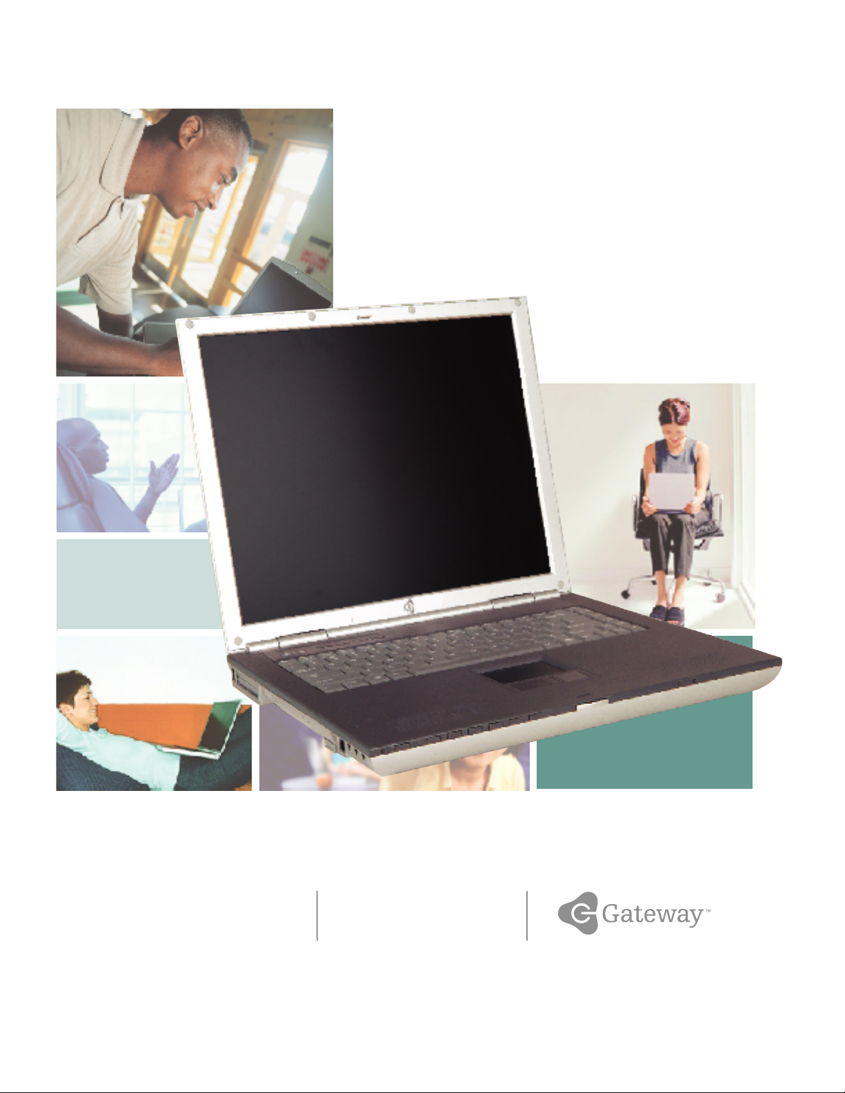
Gateway 600 Notebook
service guide
Customizing
Troubleshooting


Contents
1 Replacing Gateway 600YG2 Components . . . . . . . . . . . . . . . . . . . . . . . . 1
Identifying the notebook model . . . . . . . . . . . . . . . . . . . . . . . . . . . . . . . . . . . . . . . . . 2
Identifying components . . . . . . . . . . . . . . . . . . . . . . . . . . . . . . . . . . . . . . . . . . . . . . . 3
Preparing your work space . . . . . . . . . . . . . . . . . . . . . . . . . . . . . . . . . . . . . . . . . . . . 4
Preventing static electricity discharge . . . . . . . . . . . . . . . . . . . . . . . . . . . . . . . . . . . . 5
Preparing the notebook . . . . . . . . . . . . . . . . . . . . . . . . . . . . . . . . . . . . . . . . . . . . . . . 6
Disconnecting from the port replicator . . . . . . . . . . . . . . . . . . . . . . . . . . . . . . . . . . . 7
Removing the batteries . . . . . . . . . . . . . . . . . . . . . . . . . . . . . . . . . . . . . . . . . . . . . . . 8
Removing the main battery . . . . . . . . . . . . . . . . . . . . . . . . . . . . . . . . . . . . . . . . . 8
Removing the optional secondary battery . . . . . . . . . . . . . . . . . . . . . . . . . . . . . 9
Adding or replacing memory modules . . . . . . . . . . . . . . . . . . . . . . . . . . . . . . . . . . 11
Replacing the IEEE 802.11 Mini PCI card . . . . . . . . . . . . . . . . . . . . . . . . . . . . . . . 15
Replacing the hard drive kit . . . . . . . . . . . . . . . . . . . . . . . . . . . . . . . . . . . . . . . . . . 21
Replacing the hard drive in the hard drive kit . . . . . . . . . . . . . . . . . . . . . . . . . . . . 25
Replacing the keyboard cover . . . . . . . . . . . . . . . . . . . . . . . . . . . . . . . . . . . . . . . . . 28
Replacing the keyboard . . . . . . . . . . . . . . . . . . . . . . . . . . . . . . . . . . . . . . . . . . . . . . 31
Replacing the hinge covers . . . . . . . . . . . . . . . . . . . . . . . . . . . . . . . . . . . . . . . . . . . 37
Replacing the LCD panel assembly . . . . . . . . . . . . . . . . . . . . . . . . . . . . . . . . . . . . 39
Replacing the palm rest assembly . . . . . . . . . . . . . . . . . . . . . . . . . . . . . . . . . . . . . 46
Replacing the cooling assembly . . . . . . . . . . . . . . . . . . . . . . . . . . . . . . . . . . . . . . . 53
Replacing the LED indicator panel . . . . . . . . . . . . . . . . . . . . . . . . . . . . . . . . . . . . . 57
Replacing the speakers . . . . . . . . . . . . . . . . . . . . . . . . . . . . . . . . . . . . . . . . . . . . . . 61
Replacing the audio board . . . . . . . . . . . . . . . . . . . . . . . . . . . . . . . . . . . . . . . . . . . 65
Replacing the modem or CMOS battery . . . . . . . . . . . . . . . . . . . . . . . . . . . . . . . . . 70
Replacing the system board . . . . . . . . . . . . . . . . . . . . . . . . . . . . . . . . . . . . . . . . . . 83
i

ii

Replacing
Gateway 600YG2
Components
Important This service guide is not intended to be
provided to individual users or consumers.
It cannot be provided to anyone other than
an authorized service provider.
Use this service guide to help plan your maintenance tasks
for the Gateway 600YG2 notebook. All tasks covered in this
guide can be performed by an authorized field technician
without jeopardizing the notebook’s warranty.
For information on the notebook’s general maintenance,
technical support, safety notices, and regulatory notices,
see the Gateway user’s guide.
If you have suggestions regarding the content of this guide,
send an e-mail with the subject “Service Guide Comments”
to channel.services@gateway.com
.
© 2003 Gateway, Inc. All rights reserved. Gateway, Gateway Country, the Gateway
stylized logo, and the black-and-white spot design are trademarks or registered
trademarks of Gateway, Inc. in the United States a nd other countries. All other brands
and product names are trademarks or registered trademarks of their respective
companies.
1

Please check out our eBay auctions for more great
deals on Factory Service Manuals:
Replacing Gateway 600YG2 Components
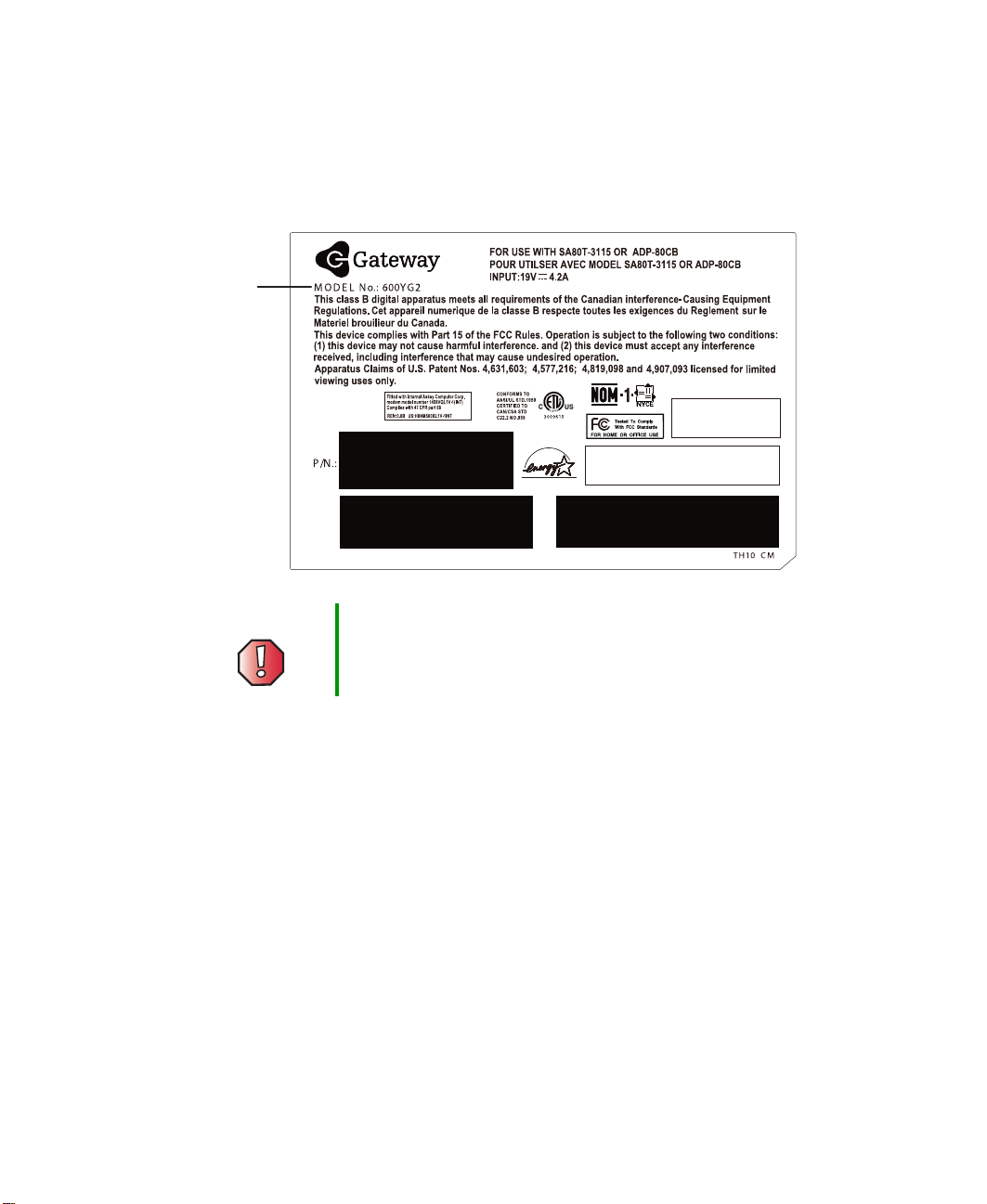
Identifying the notebook model
The label on the bottom of the notebook contains information that identifies
the notebook model and its features.
Gateway
model
number
™
Warning It is important that you use the correct service guide for
the notebook. Failure to follow the approved tasks for the
notebook model may result in damage to the notebook.
2
www.gateway.com
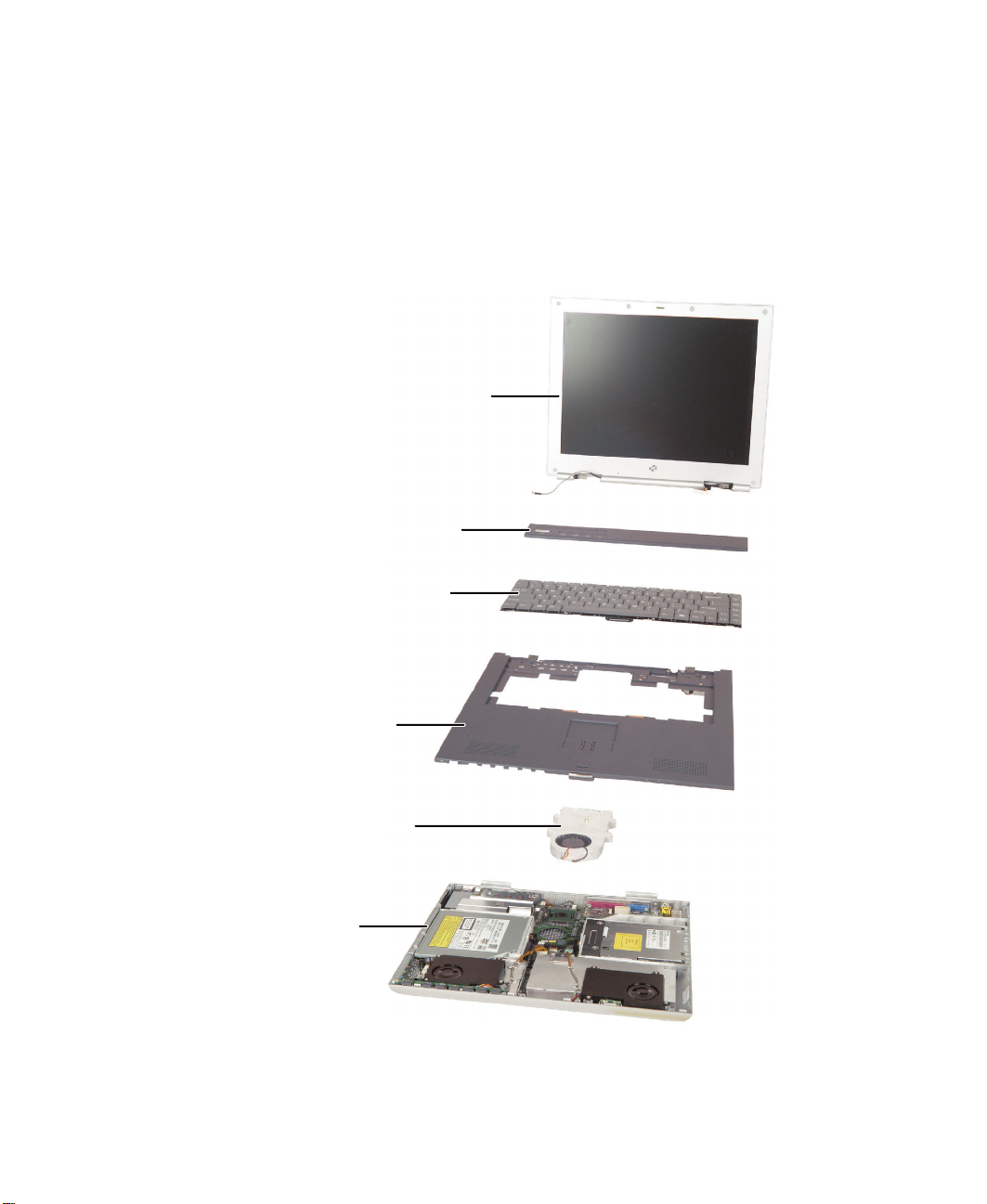
Identifying components
Identifying components
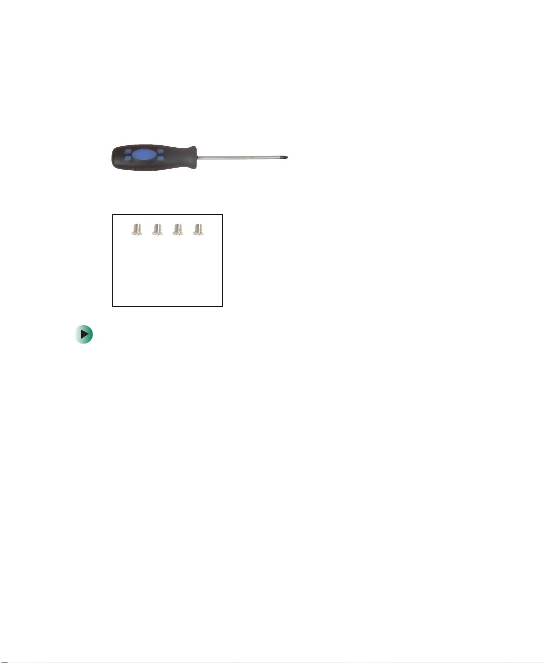
Where screw measurements are shown, the first number indicates screw head
width, and the second number indicates screw length.
Use this chart to identify the main components of the notebook. For a complete
list of replaceable parts, see the Contents.
LCD panel assembly
(see page 39)
Keyboard cover
(see page 28)
Keyboard
(see page 31)
Palm rest assembly
(see page 46)
Cooling assembly
(see page 53)
System board
(see page 83)
www.gateway.com
3

Replacing Gateway 600YG2 Components
Preparing your work space
Before performing maintenance on the notebook, make sure that your work
space and the notebook are correctly prepared.
■ Wear a grounding (ESD) wrist strap, and use a grounded or dissipative work
mat.
■ Use a stable and strong table, and make sure that the table top is large
enough to hold each component as you remove it.
■ Use bright lighting to make part identification easier.
■ Keep your work surface free from clutter and dust that may damage
components.
■ Use a magnetized screwdriver for removing screws.
■ When removing components that are attached to the notebook by a cable,
unplug the cable before removing the screws, when possible, to avoid
damaging the cable.
■ As you remove components and screws, lay them toward the rear of your
work surface (behind the notebook) or far enough to the side that your
arms do not accidentally brush them onto the floor.
■ To help keep track of screws, try the following:
■ Place each component’s screws in their own section of a parts sorter.
■ Place each component’s screws next to the component on your work
surface.
■ Print the first page of each task, then place the page toward the rear
of your work surface. As you remove screws, place the screws in their
respective boxes on the page. Where screw measurements are shown,
the first number indicates screw head width, and the second number
indicates screw length.
■ After loosening screws that are deeply recessed in a hole (for example,
on the bottom of the base assembly), you can leave the screws in the
holes if you place small pieces of masking tape over the hole openings.
When reassembling the component, just remove the tape and tighten
the screws.
■ When you place flat-headed screws on your work surface, stand them
on their heads to prevent the screws from rolling off the table.
4
www.gateway.com
Preventing static electricity discharge
Preventing static electricity
discharge
The components inside the notebook are extremely sensitive to static electricity,
also known as electrostatic discharge (ESD).
Warning ESD can permanently damage electrostatic
discharge-sensitive components in the notebook. Prevent
ESD damage by following ESD guidelines every time you
open the notebook case.
Warning To avoid exposure to dangerous electrical voltages and
moving parts, turn off the notebook and unplug the power
cord and modem and network cable before opening the
case.
Before replacing components, follow these guidelines:
■ Turn off the notebook.
■ Wear a grounding wrist strap (available at most electronics stores) and
attach it to a bare metal part of your workbench or other grounded
connection.
Warning To prevent risk of electric shock, do not insert any object
into the vent holes of the notebook.
■ Touch a bare metal surface on your workbench or other grounded object.
■ Unplug the power cord and the modem and network cables.
■ Remove the main and optional secondary batteries. For more information,
see “Removing the batteries” on page 8.
■ Disconnect all peripheral devices and remove any PC Cards.
www.gateway.com
5

Replacing Gateway 600YG2 Components
Before working with notebook components, follow these guidelines:
■ Avoid static-causing surfaces such as carpeted floors, plastic, and packing
foam.
■ Remove components from their antistatic bags only when you are ready
to use them. Do not lay components on the outside of antistatic bags
because only the inside of the bags provide electrostatic protection.
■ Always hold components by their edges. Avoid touching the edge
connectors. Never slide components over any surface.
Preparing the notebook
Warning To avoid exposure to dangerous electrical voltages and
moving parts, turn off the notebook, remove the main and
optional secondary batteries, and unplug the power cord
and modem and network cables before opening the case.
Replace the cover before you restore power or reconnect
the modem and network cables.
To prepare the notebook for maintenance:
■ Make sure that the modular drive is empty.
■ Disconnect all peripheral devices and remove any PC Cards.
■ Turn off the notebook and unplug the power cord and modem and network
cables (if attached).
■ Disconnect the notebook from the optional port replicator. For more
information see “Disconnecting from the port replicator” on page 7.
■ Turn over the notebook and remove the main and optional secondary
batteries. For more information see “Removing the batteries” on page 8.
6
www.gateway.com
Disconnecting from the port replicator
Disconnecting from the port
replicator
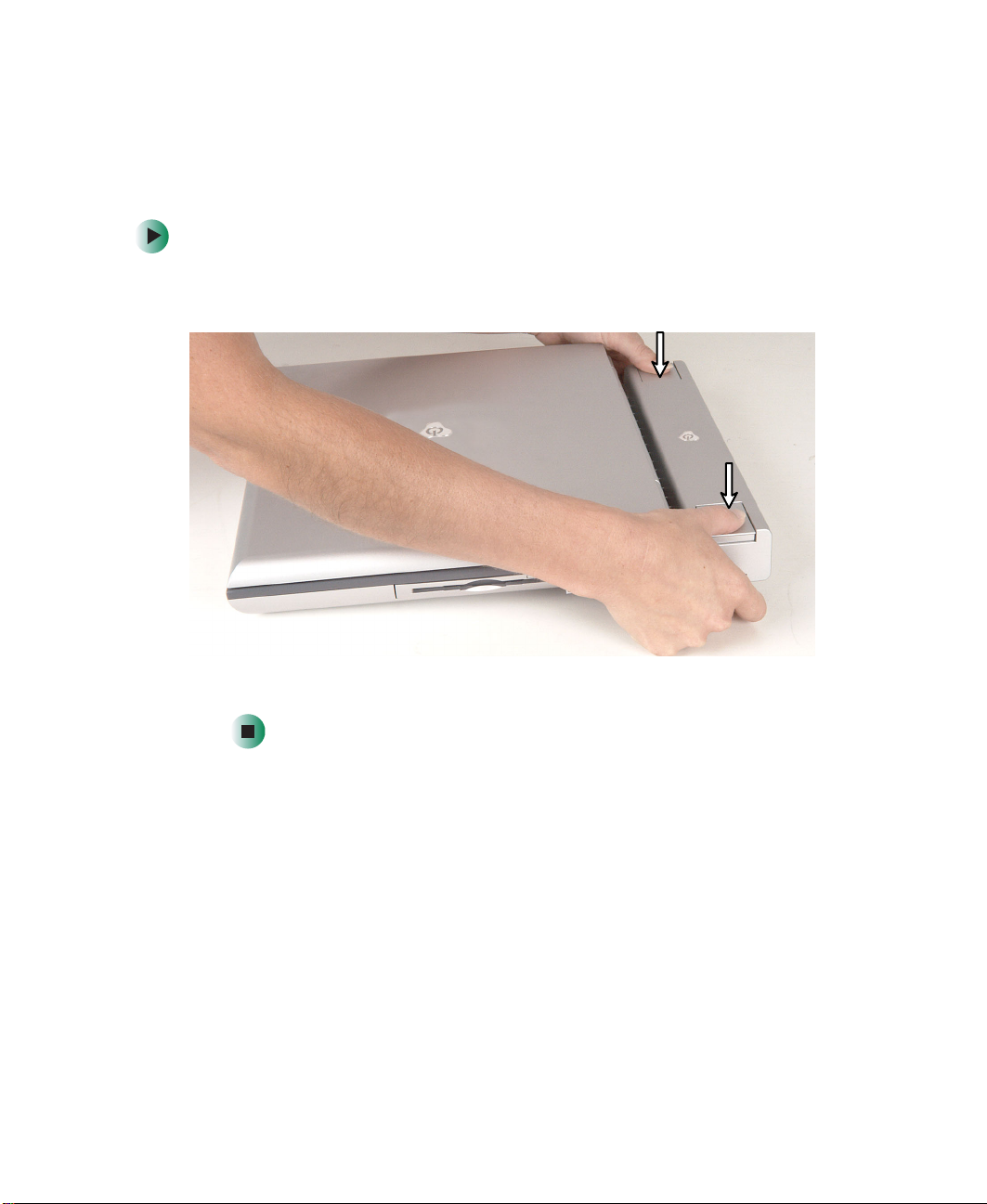
To separate the notebook from the port replicator:
1 Press down on both docking release latches. The notebook will spring up
slightly.
2 Lift the notebook off of the port replicator.
www.gateway.com
7
Replacing Gateway 600YG2 Components
Removing the batteries
Removing the main battery
To remove the main battery:
1 Disconnect the AC adapter and modem and network cables and prepare
the notebook by following the instructions in “Preparing the notebook”
on page 6.
2 Disconnect the notebook from the optional port replicator by following
the instructions in “Disconnecting from the port replicator” on page 7.
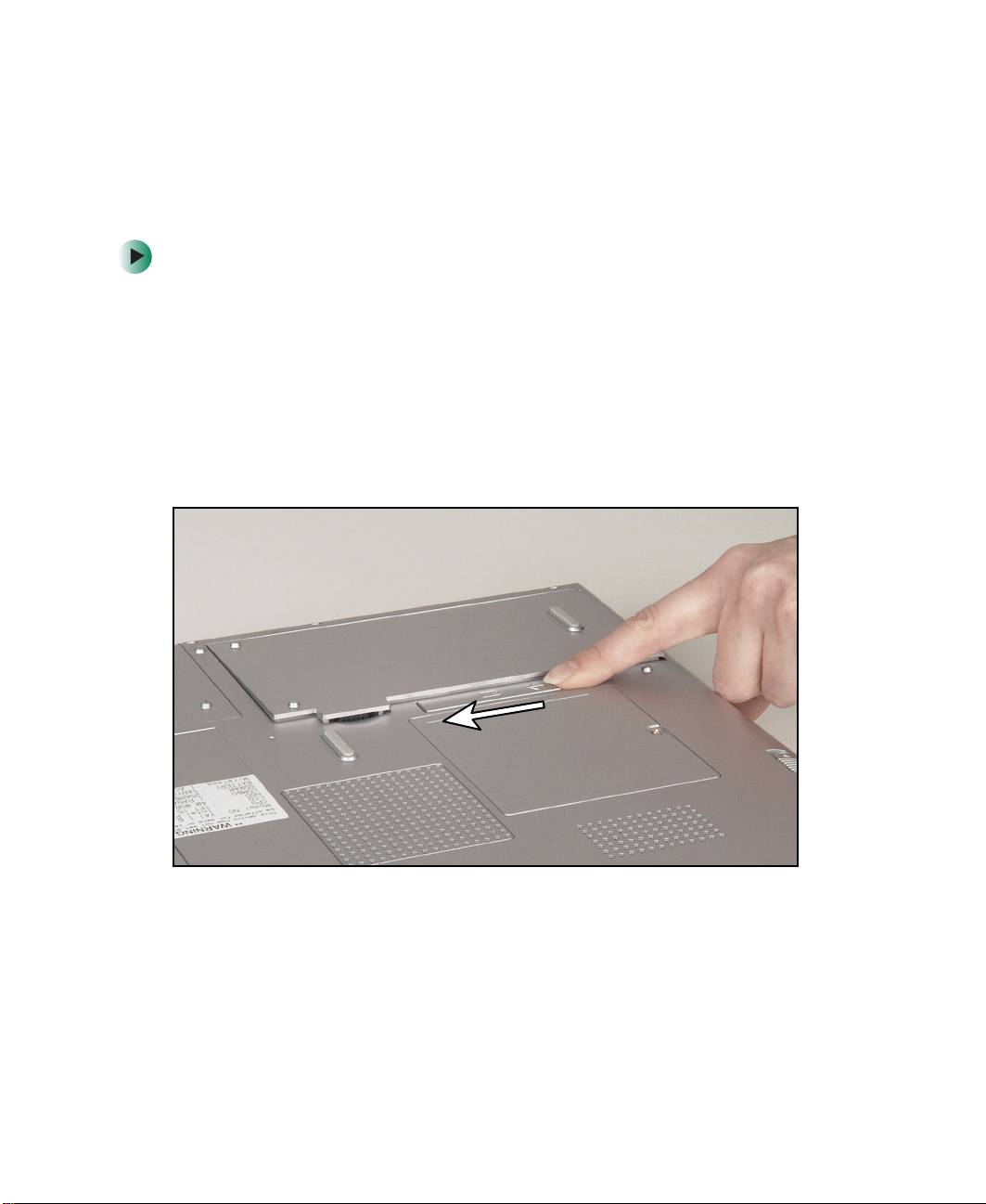
3 Turn the notebook over so the bottom is facing up.
4 Slide the battery release latch.
8
www.gateway.com
Removing the batteries
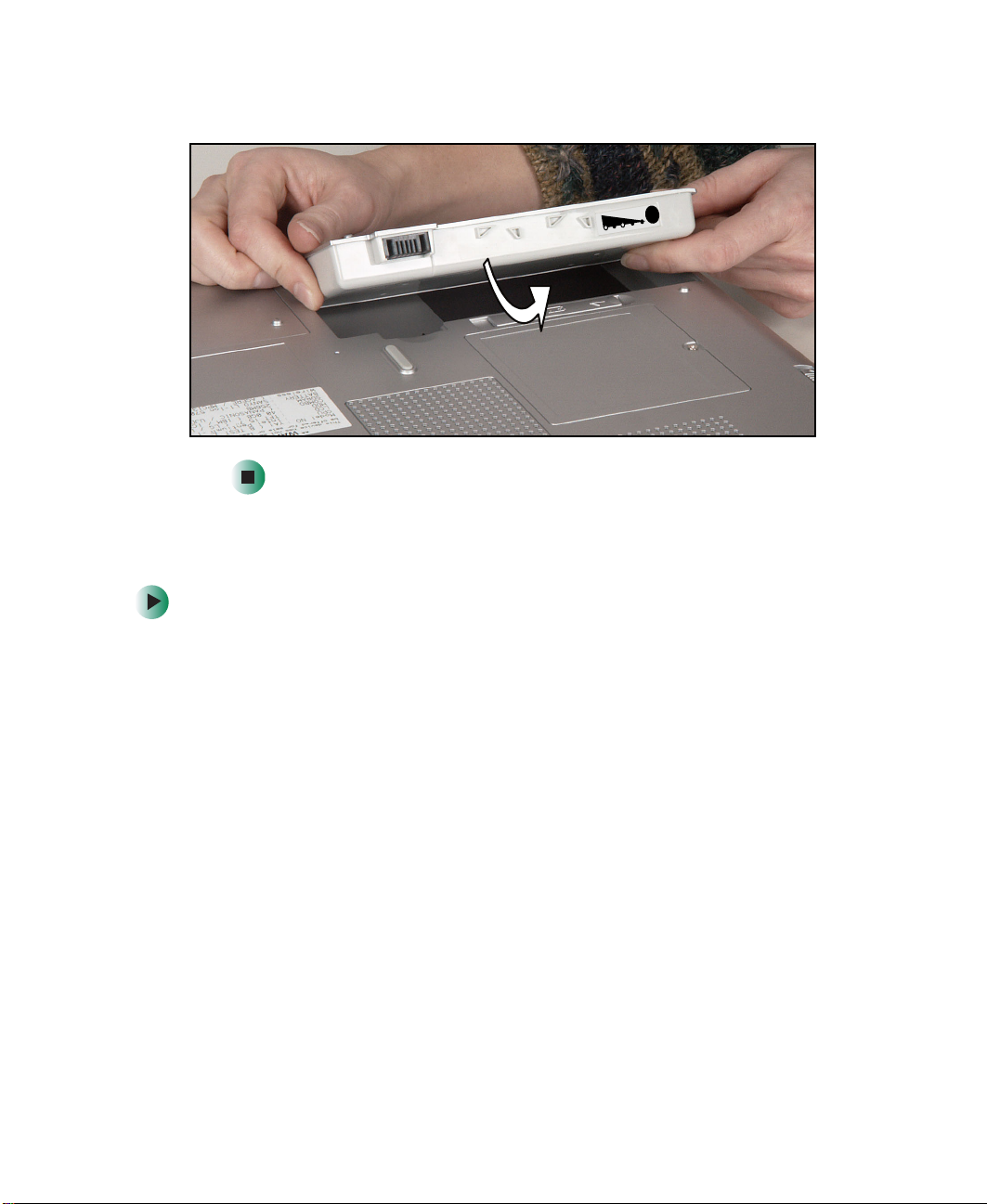
5 Lift the battery out of the bay.
0
2
0
4
0
6
0
8
0
0
1
Removing the optional secondary battery
To remove the secondary battery:
1 Disconnect the AC adapter and modem and network cables and prepare
the notebook by following the instructions in “Preparing the notebook”
on page 6.
2 Disconnect the notebook from the optional port replicator by following
the instructions in “Disconnecting from the port replicator” on page 7.
3 Turn the notebook over so the bottom is facing up.
www.gateway.com
9
Replacing Gateway 600YG2 Components
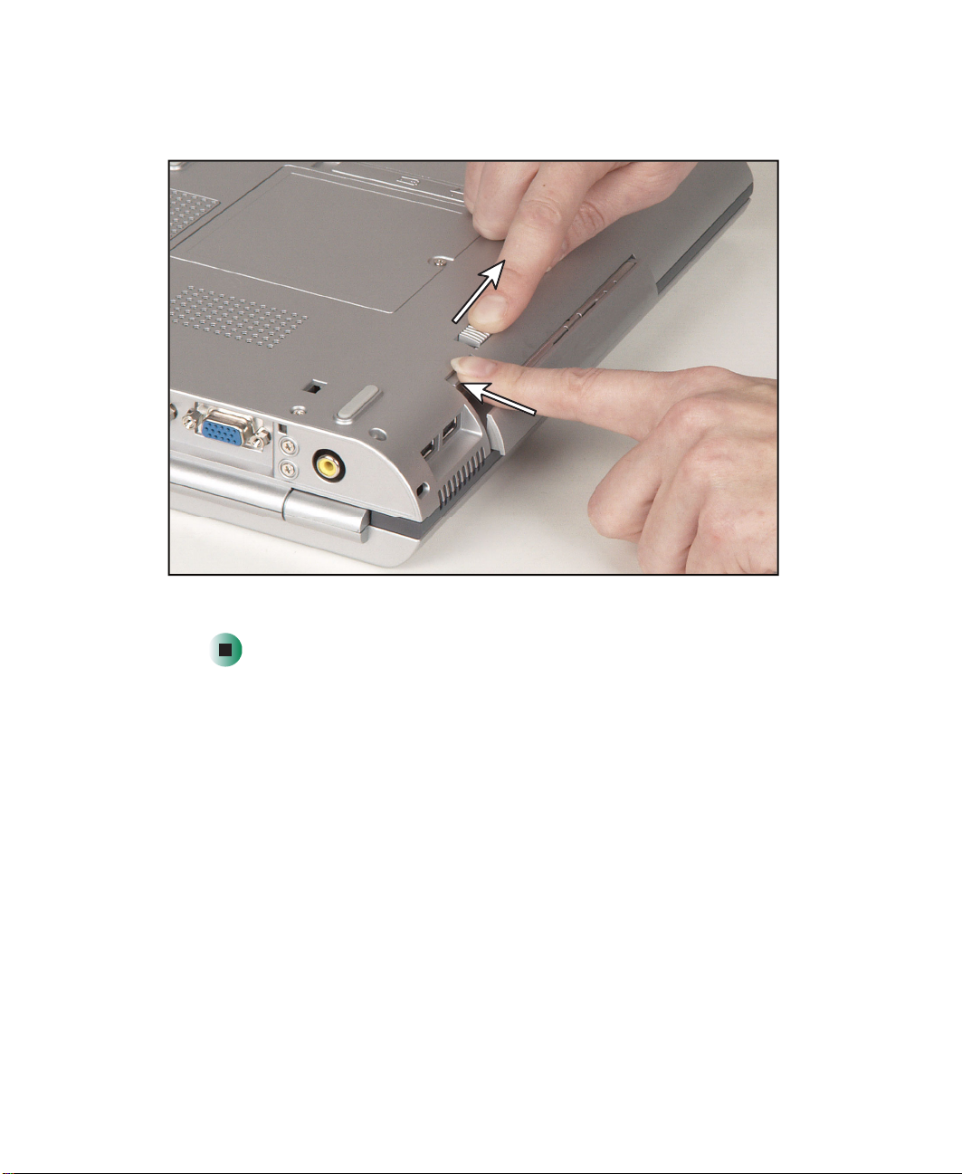
4 Slide and hold the modular bay latch and press the modular bay release
button. The battery moves out slightly.
10
5 Slide the battery out.
www.gateway.com
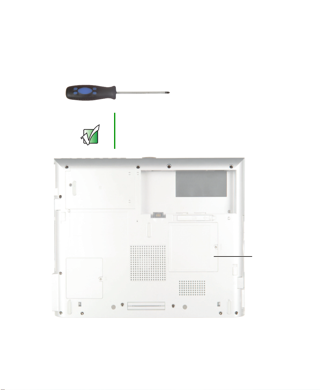
Adding or replacing memory modules
Adding or replacing memory
modules
Tools you need to complete this task:
Phillips #0 screwdriver
Important Use only memory modules designed for the
Gateway 600YG2.
www.gateway.com
Memory
bay
11
Replacing Gateway 600YG2 Components
To add or replace memory modules:
1 Disconnect the AC adapter and modem and network cables and prepare
the notebook by following the instructions in “Preparing your work space”
on page 4.
2 Disconnect the notebook from the optional port replicator by following
the instructions in “Disconnecting from the port replicator” on page 7.
3 Turn the notebook over so the bottom is facing up.
4 Remove the main and optional secondary batteries by following the
instructions in “Removing the batteries” on page 8.
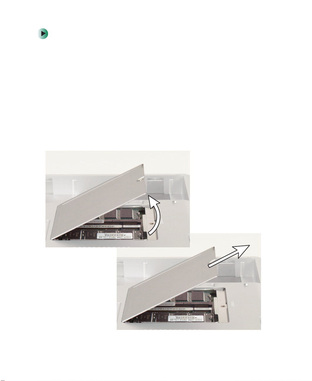
5 Loosen the captive screw that secures the memory cover. (The screw cannot
be removed.)
6 Lift the screw side of the cover upward, then slide the cover out.
12
www.gateway.com
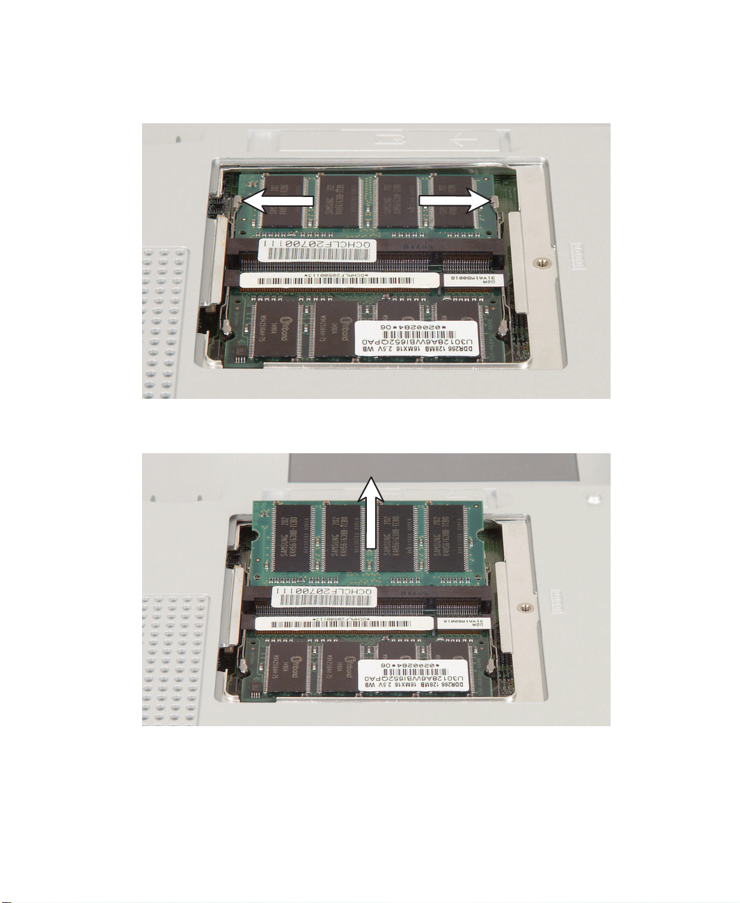
Adding or replacing memory modules
7 If you are removing a module, gently press outward on the clip at each
end of the memory module until the module tilts upward.
8 Pull the memory module out of the slot.
www.gateway.com
13

Replacing Gateway 600YG2 Components
9 Hold the new or replacement module at a 30-degree angle and press it into
the empty memory slot. This module is keyed so it can only be inserted
in one direction. If the module does not fit, make sure that the notch in
the module lines up with the tab in the memory slot.
10 Gently press the module down until it clicks into place.
11 Replace the memory cover and tighten the captive screw.
14
www.gateway.com
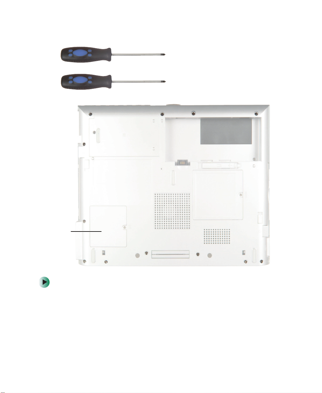
Replacing the IEEE 802.11 Mini PCI card
Replacing the IEEE 802.11 Mini PCI
card
Caution By law, only approved wireless modules provided by
Gateway, or a Gateway authorized representative,
explicitly for the Gateway 600YG2 may be installed in this
notebook.
Caution Legal requirements dictate that a security screw (or other
means) be used to attach the mini-PCI cover to the chassis
in a manner that restricts end user access. End users are
strictly prohibited from having access to the wireless card.
Due to manufacturing process changes, Gateway 600YG2
notebooks manufactured after August 7, 2003 require a
Torx head security screw to attach the mini-PCI cover.
Caution Legal requirements dictate the mini-PCI cover be in place
during any and all operation of the notebook’s wireless
feature.
www.gateway.com
15
Replacing Gateway 600YG2 Components
Tools you need to complete this task:
Phillips #0 screwdriver
-OR-
Torx T8 screwdriver
Mini PCI
bay
To replace the IEEE 802.11 Mini PCI card:
1 Disconnect the AC adapter and modem and network cables and prepare
the notebook by following the instructions in “Preparing your work space”
on page 4.
2 Disconnect the notebook from the optional port replicator by following
the instructions in “Disconnecting from the port replicator” on page 7.
3 Turn the notebook over so the bottom is facing up.
16
www.gateway.com
Replacing the IEEE 802.11 Mini PCI card
4 Remove the main and optional secondary batteries by following the
instructions in “Removing the batteries” on page 8.
5 Use the appropriate screwdriver to loosen the captive screw that secures
the Mini PCI cover. (The screw cannot be removed.)
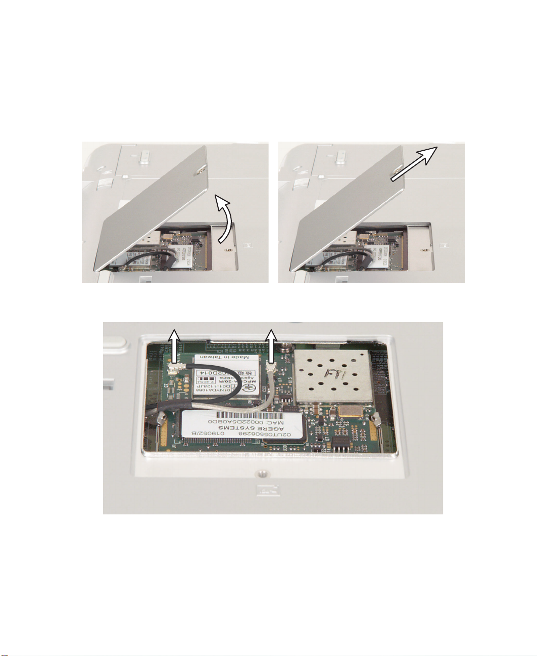
6 Lift the screw side of the cover upward, then slide the cover out.
7 Unplug the two antenna cables.
www.gateway.com
17

Replacing Gateway 600YG2 Components
8 Move the antenna wires out of the way, then press outward on the clips
at both sides of the module until the module tilts upward.
18
www.gateway.com
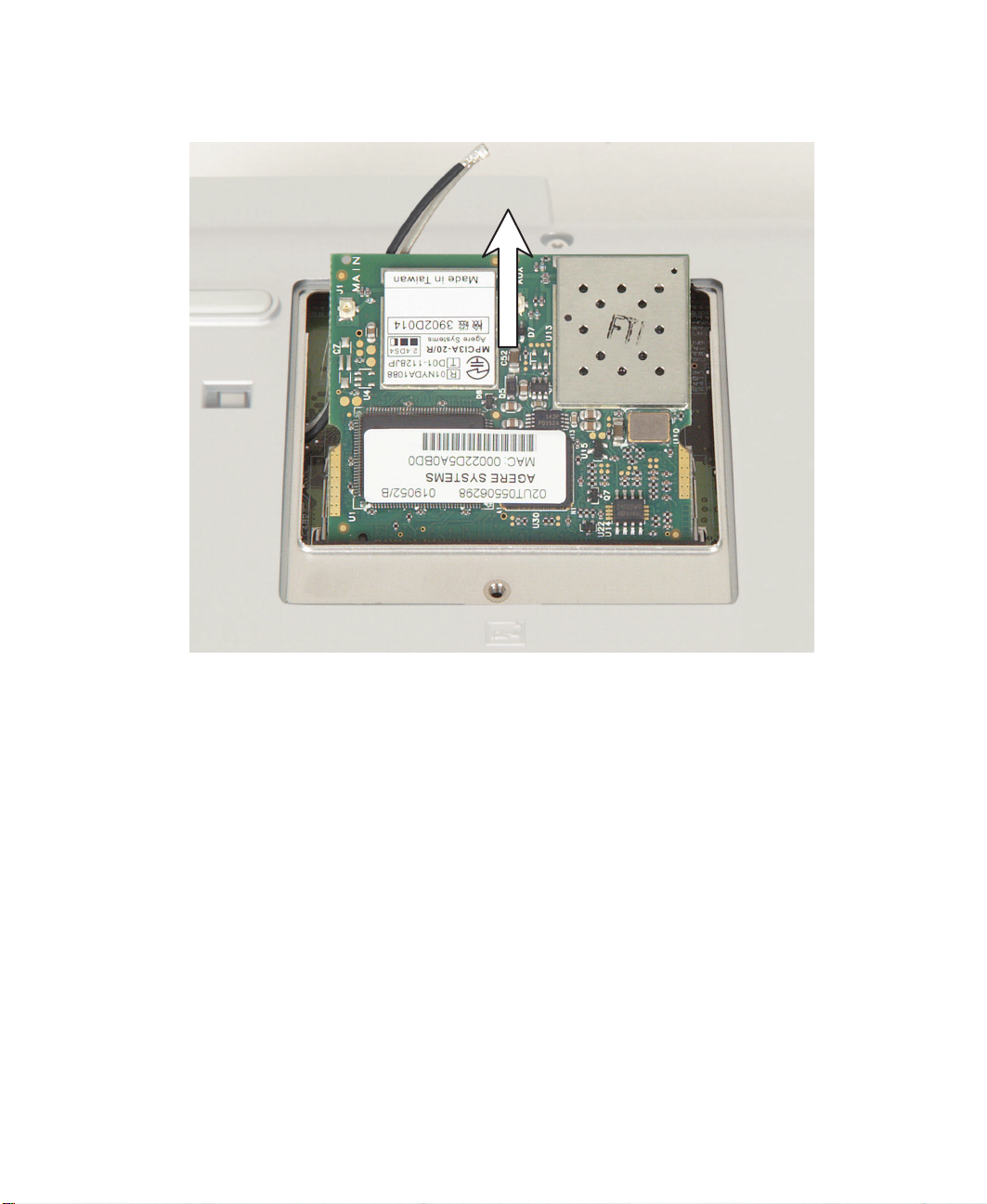
9 Pull the module out of the slot.
Replacing the IEEE 802.11 Mini PCI card
10 Hold the new module at a 30-degree angle and press it into the empty slot.
This module is keyed so it can only be inserted in one direction. If the
module does not fit, make sure that the notch in the module lines up with
the tab in the module slot.
11 Move the antenna wires out of the way, then press the module down until
it clicks into place.
www.gateway.com
19
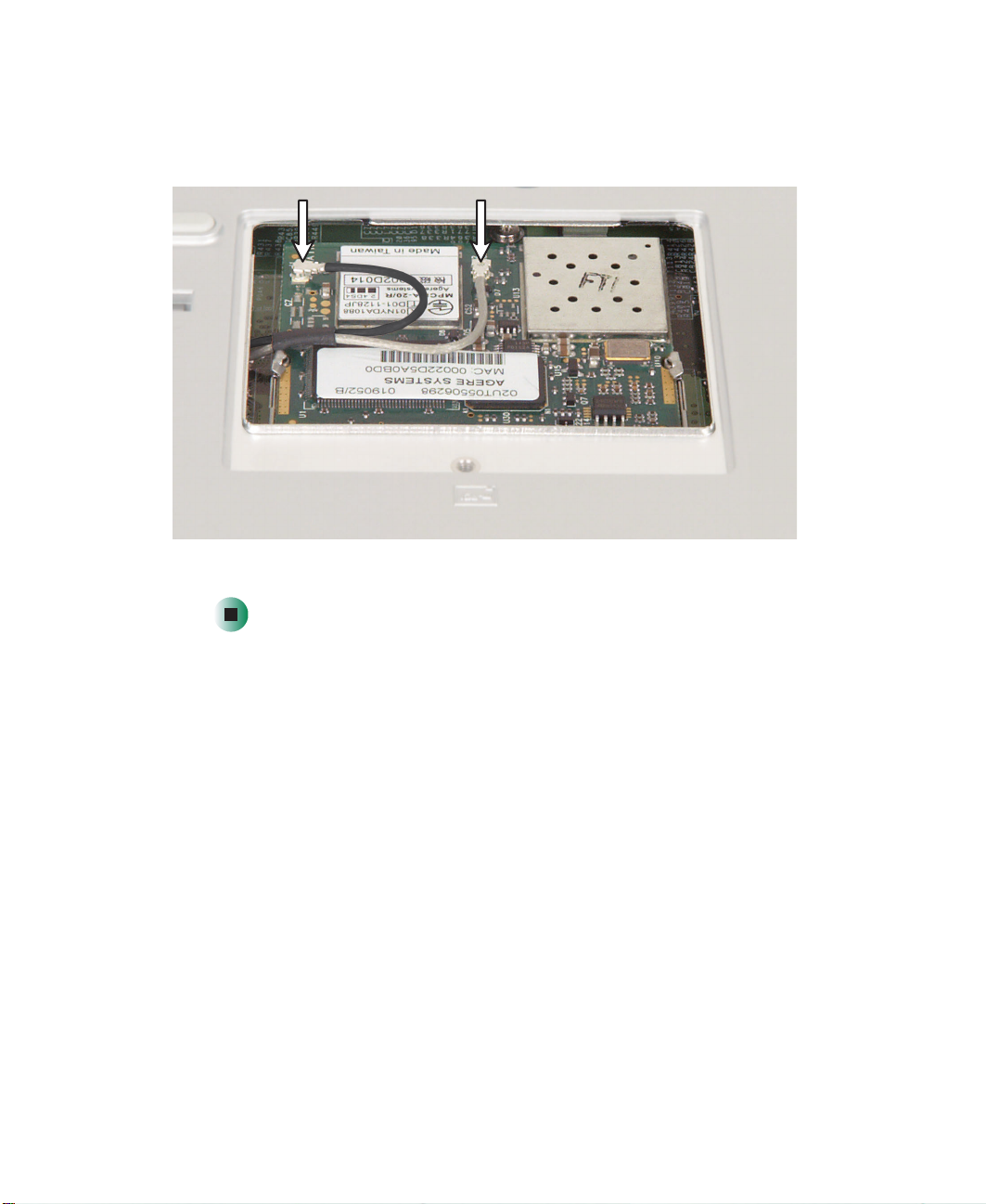
Replacing Gateway 600YG2 Components
12 Reattach the black antenna cable to the connector labelled MAIN or M,
then reattach the light gray antenna cable to the connector labelled AUX
or A.
13 Replace the Mini PCI cover, then tighten the captive screw.
20
www.gateway.com
Replacing the hard drive kit
Replacing the hard drive kit
Tools you need to complete this task:
Phillips #0 screwdriver
To replace the hard drive kit:
1 Disconnect the AC adapter and modem and network cables and prepare
the notebook by following the instructions in “Preparing your work space”
on page 4.
2 Disconnect the notebook from the optional port replicator by following
the instructions in “Disconnecting from the port replicator” on page 7.
3 Turn the notebook over so the bottom is facing up.
4 Remove the main and optional secondary batteries by following the
instructions in “Removing the batteries” on page 8.
www.gateway.com
21
Replacing Gateway 600YG2 Components
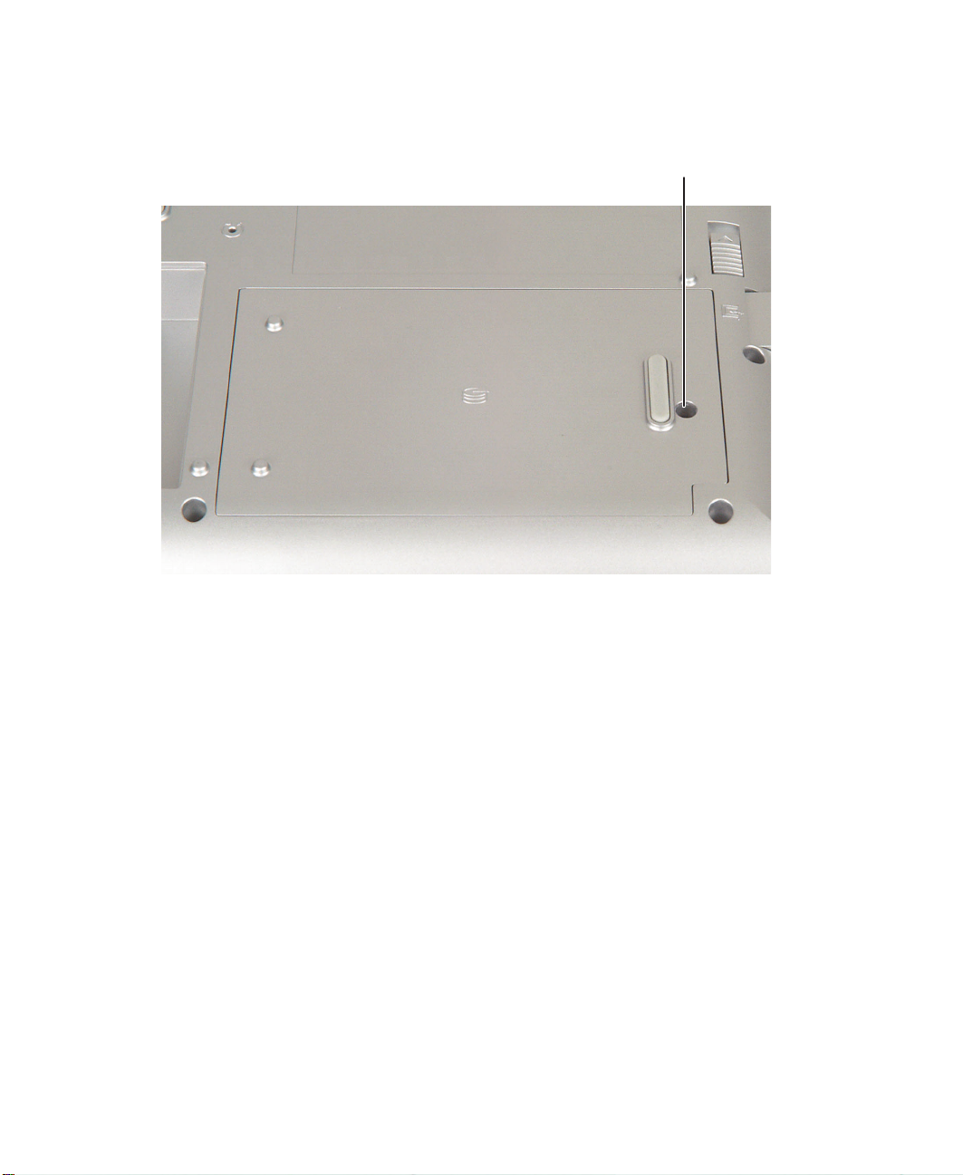
5 Loosen the captive screw that secures the hard drive cover. (The screw
cannot be removed.)
Screw
22
www.gateway.com
Replacing the hard drive kit
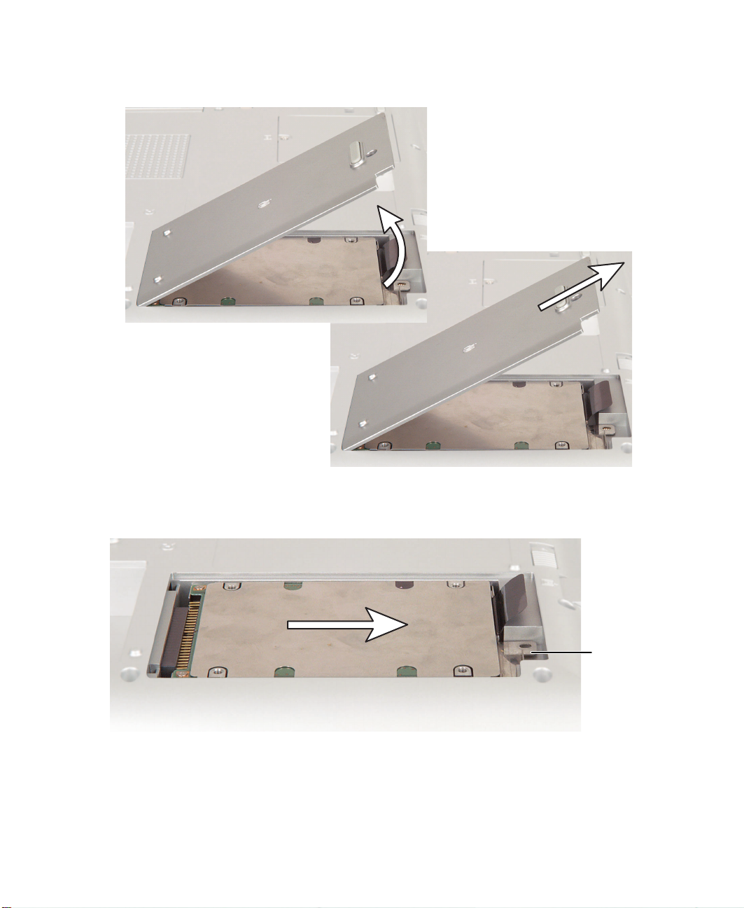
6 Lift the screw side of the cover upward, then slide the cover out.
7 Pull on the metal flange to disconnect the hard drive kit from the
connector.
Flange
www.gateway.com
23
Replacing Gateway 600YG2 Components
8 Lift the plastic tab on the hard drive kit, then lift the kit out of the
notebook.
Ta b
24
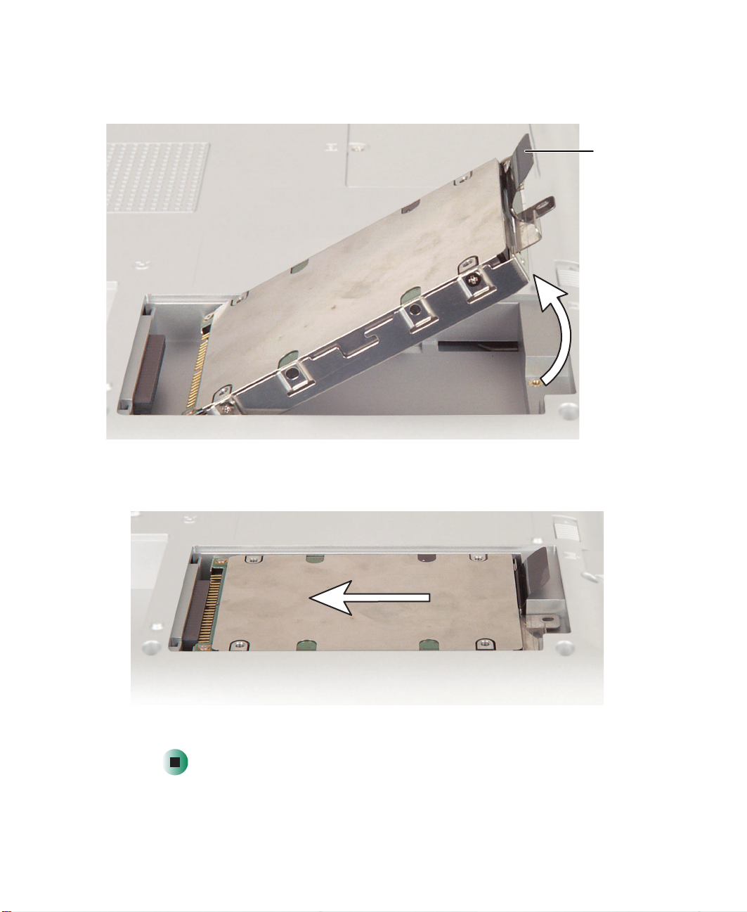
9 Place the new hard drive kit into the drive bay, then slide the drive onto
the connector.
10 Replace the cover and tighten the screw.
www.gateway.com
Replacing the hard drive in the hard drive kit
Replacing the hard drive in the
hard drive kit
Tools you need to complete this task:
Phillips #0 screwdriver
Screws removed during this task:
4 chrome 3 × 3.5 mm
(hard drive)
To install a new hard drive into the kit:
1 Disconnect the AC adapter and modem and network cables and prepare
the notebook by following the instructions in “Preparing your work space”
on page 4.
2 Disconnect the notebook from the optional port replicator by following
the instructions in “Disconnecting from the port replicator” on page 7.
3 Turn the notebook over so the bottom is facing up.
4 Remove the main and optional secondary batteries by following the
instructions in “Removing the batteries” on page 8.
5 Remove the hard drive kit by following the instructions in “Replacing the
hard drive kit” on page 21.
www.gateway.com
25

Replacing Gateway 600YG2 Components
6 Remove the four screws that secure the hard drive to the hard drive kit
bracket.
Screw
Screw
Bracket
Screw
26
Screw
7 Remove the old drive from the bracket.
www.gateway.com

Replacing the hard drive in the hard drive kit
8 Insert the new drive into the bracket so the screw holes line up, then
replace the four screws that secure the drive to the bracket.
Screw
Screw
Screw
Bracket
Screw
9 Place the new hard drive kit into the drive bay, then slide the drive onto
the connector.
10 Replace the cover and tighten the screw.
www.gateway.com
27

Replacing Gateway 600YG2 Components
Replacing the keyboard cover
Tools you need to complete this task:
Flat-blade driver Scribe or non-marring tool- OR -
To replace the keyboard cover:
1 Disconnect the AC adapter and modem and network cables and prepare
the notebook by following the instructions in “Preparing your work space”
on page 4.
2 Disconnect the notebook from the optional port replicator by following
the instructions in “Disconnecting from the port replicator” on page 7.
3 Turn the notebook over so the bottom is facing up.
4 Remove the main and optional secondary batteries by following the
instructions in “Removing the batteries” on page 8.
28
5 Turn the notebook over so the top is facing up.
6 Open the LCD panel to the normal viewing position.
www.gateway.com

Replacing the keyboard cover
7 Insert the small flat-blade screwdriver or non-marring tool under the
bottom right corner of the keyboard cover and gently pry it up.
Important Inserting a piece of cloth between the screwdriver and
keyboard and notebook case will help prevent damage to
the notebook.
8 Pull the cover off the notebook. You will hear small snapping sounds as
the cover comes away from the notebook. Be careful not to break off the
tabs found on the left end of the cover.
www.gateway.com
29

Replacing Gateway 600YG2 Components
9 Slide the two tabs on the left end of the new cover under the notebook
frame.
10 Press down on the cover in several places until it clicks in place. The cover
is correctly mounted when you can run you finger along the cover and
find no loose spots. The cover should be flat all the way across.
Press PressPress
30
Warning If the cover is not correctly replaced, the notebook could
be damaged when you try to close the LCD panel.
www.gateway.com

Replacing the keyboard
Tools you need to complete this task:
Flat-blade driver Scribe or non-marring tool- OR -
Phillips #0 screwdriver
Screws removed during this task:
5 chrome 2.5×4mm
(keyboard)
Replacing the keyboard
To remove the keyboard:
1 Disconnect the AC adapter and modem and network cables and prepare
the notebook by following the instructions in “Preparing your work space”
on page 4.
2 Disconnect the notebook from the optional port replicator by following
the instructions in “Disconnecting from the port replicator” on page 7.
3 Turn the notebook over so the bottom is facing up.
4 Remove the main and optional secondary batteries by following the
instructions in “Removing the batteries” on page 8.
5 Turn the notebook over so the top is facing up.
6 Remove the keyboard cover by following the instructions in “Replacing
the keyboard cover” on page 28.
www.gateway.com
31

Replacing Gateway 600YG2 Components
7 Remove the five keyboard screws that secure the keyboard to the notebook.
Important There may be a grounding strap attached to the far-right
screw. Make sure this strap is free from the keyboard
before continuing.
Screws
32
8 Lift the back edge of the keyboard slightly, then carefully slide the keyboard
back until the four tabs on the front edge of the keyboard are free from
their slots. Be careful not to damage the LCD panel.
www.gateway.com

Replacing the keyboard
9 Slowly rotate the keyboard toward you so it lies keys-down on top of the
notebook. Be careful not to damage the LCD panel.
www.gateway.com
33

Replacing Gateway 600YG2 Components
10 Use two fingers to unplug the keyboard panel connector from the
notebook. Be careful not to touch or damage any other components.
11 Place the new keyboard keys-down on the notebook with the space bar
away from you.
34
www.gateway.com

Replacing the keyboard
12 Insert the keyboard plug, on the end of the keyboard cable, onto the
keyboard connector.
Important The outside of the keyboard plug goes around the
keyboard connector. The plug is correctly oriented if the
cable is not twisted.
13 Rotate the keyboard toward the LCD panel until the keyboard is almost
face-up.
www.gateway.com
35

Replacing Gateway 600YG2 Components
14 Insert the four tabs located on the front edge of the keyboard into the
corresponding slots under the palm rest.
15 Gently press the keyboard down until it is flat all the way across. The
keyboard should easily fall into place. Be careful not to damage the
LCD panel.
Tabs
36
16 Replace the five keyboard screws. If a grounding strap was connected to
the far-right screw, make sure to reconnect it.
17 Reassemble the notebook.
www.gateway.com

Replacing the hinge covers
Tools you need to complete this task:
Flat-blade driver Scribe or non-marring tool- OR -
Phillips #0 screwdriver
Screws removed during this task:
4 chrome 2.5×5mm
(hinge covers)
Replacing the hinge covers
To replace the hinge covers:
1 Disconnect the AC adapter and modem and network cables and prepare
the notebook by following the instructions in “Preparing your work space”
on page 4.
2 Disconnect the notebook from the optional port replicator by following
the instructions in “Disconnecting from the port replicator” on page 7.
3 Turn the notebook over so the bottom is facing up.
4 Remove the main and optional secondary batteries by following the
instructions in “Removing the batteries” on page 8.
5 Turn the notebook over so the top is facing up.
6 Remove the keyboard cover by following the instructions in “Replacing
the keyboard cover” on page 28.
7 Open the LCD panel all the way, so it lies flat on the table.
www.gateway.com
37

Replacing Gateway 600YG2 Components
8 Remove the four screws that secure the hinge covers to the notebook.
Screws Screws
9 Lift the hinge covers off the hinges.
10 Snap the new covers into place over the hinges, then replace the four
screws.
11 Reassemble the notebook.
38
www.gateway.com

Replacing the LCD panel assembly
Replacing the LCD panel assembly
Tools you need to complete this task:
Flat-blade driver Scribe or non-marring tool- OR -
Phillips #0 screwdriver
Torx T8 screwdriver
Screws removed during this task:
4 chrome 2.5×5mm
(hinge covers)
4 or 6 chrome 2.5 × 7 mm
(LCD panel hinges)
To replace the LCD panel assembly:
1 Disconnect the AC adapter and modem and network cables and prepare
the notebook by following the instructions in “Preparing your work space”
on page 4.
2 Disconnect the notebook from the optional port replicator by following
the instructions in “Disconnecting from the port replicator” on page 7.
3 Turn the notebook over so the bottom is facing up.
4 Remove the main and optional secondary batteries by following the
instructions in “Removing the batteries” on page 8.
5 If the notebook has IEEE 802.11 wireless networking built in, remove the
IEEE 802.11 Mini PCI module by following the instructions in “Replacing
the IEEE 802.11 Mini PCI card” on page 15.
6 Turn the notebook over so the top is facing up.
www.gateway.com
39

Replacing Gateway 600YG2 Components
7 Remove the keyboard cover by following the instructions in “Replacing
the keyboard cover” on page 28.
8 Remove the hinge covers by following the instructions in “Replacing the
hinge covers” on page 37.
9 Use a flat-blade screwdriver or chip puller to carefully unplug the LCD
video cable from the notebook. Make sure you grasp the connector, not
the cable.
Warning The connector is fragile. When using a flat-blade
screwdriver to remove the connector, pry up one side
slightly, then pry up the other side slightly. Continue
alternating from side-to-side until the connector comes
loose.
- OR -
40
www.gateway.com

Replacing the LCD panel assembly
10 If the notebook has IEEE 802.11 wireless networking built in, carefully pull
the detached IEEE 802.11 antenna cables through the opening near the
left hinge. To prevent the antenna cables from snagging on other
components, keep the antenna connectors close together by moving the
cable wrap close to the connectors.
www.gateway.com
41

Replacing Gateway 600YG2 Components
11 Remove the four (or six, depending on screen size) hinge screws. There is
an LCD panel ground cable attached to a screw on the right hinge. Make
sure that this cable is free before continuing.
Screws Screws
12 Move the LCD panel upright, then lift it from the notebook. The LCD panel
assembly is now completely detached from the notebook.
42
www.gateway.com

Replacing the LCD panel assembly
13 Place the new LCD panel assembly onto the notebook, then replace the
four (or six, depending on screen size) hinge screws. Make sure that you
connect the LCD panel’s ground cable to the left screw of the right hinge.
LCD panel ground cable
14 Plug the LCD video cable into the notebook.
www.gateway.com
43

Replacing Gateway 600YG2 Components
15 If the notebook has IEEE 802.11 built in, carefully thread the antenna
cables through the opening near the left hinge until they protrude into
the Mini PCI bay. To prevent the antenna cables from snagging on other
components, move the cable wrap close to the connectors.
44
www.gateway.com

Replacing the LCD panel assembly
16 If the notebook has IEEE 802.11 built in, slide the cable wrap down about
two inches from the connectors to allow the connectors to widely separate.
17 Reattach the black antenna cable to the connector labelled MAIN or M,
then reattach the light gray antenna cable to the connector labelled AUX
or A.
18 Reassemble the notebook.
Caution Legal requirements dictate that a security screw (or other
means) be used to attach the mini-PCI cover to the chassis
in a manner that restricts end user access. End users are
strictly prohibited from having access to the wireless card.
Due to manufacturing process changes, Gateway 600YG2
notebooks manufactured after August 7, 2003 require a
Torx head security screw to attach the mini-PCI cover.
Caution Legal requirements dictate the mini-PCI cover be in place
during any and all operation of the notebook’s wireless
feature.
www.gateway.com
45

Replacing Gateway 600YG2 Components
Replacing the palm rest assembly
Tools you need to complete this task:
Flat-blade driver Scribe or non-marring tool- OR -
Phillips #0 screwdriver
Torx T8 screwdriver
Screws removed during this task:
5 chrome 2.5×4mm
(keyboard)
13 chrome 2.5 × 5 mm
(bottom)
To replace the palm rest assembly:
1 Disconnect the AC adapter and modem and network cables and prepare
the notebook by following the instructions in “Preparing your work space”
on page 4.
2 Disconnect the notebook from the optional port replicator by following
the instructions in “Disconnecting from the port replicator” on page 7.
3 Turn the notebook over so the bottom is facing up.
46
4 chrome 2.5×5mm
(hinge covers)
4 chrome 2.5×5mm
(back)
www.gateway.com
4 or 6 chrome 2.5 × 7 mm
(LCD panel hinges)
1 chrome 2.5 × 7 mm
(near touchpad)
1 chrome 2.5 × 4 mm
(near multifunction
buttons) (palm rest)

Replacing the palm rest assembly
4 Remove the main and optional secondary batteries by following the
instructions in “Removing the batteries” on page 8.
5 If the notebook has IEEE 802.11 wireless networking built in, remove the
IEEE 802.11 Mini PCI module by following the instructions in “Replacing
the IEEE 802.11 Mini PCI card” on page 15.
6 Turn the notebook over so the top is facing up.
7 Remove the keyboard cover by following the instructions in “Replacing
the keyboard cover” on page 28.
8 Remove the keyboard by following the instructions in “Replacing the
keyboard” on page 31.
9 Remove the hinge covers by following the instructions in “Replacing the
hinge covers” on page 37.
10 Remove the LCD panel by following the instructions in “Replacing the
LCD panel assembly” on page 39.
www.gateway.com
47

Replacing Gateway 600YG2 Components
11 Turn the notebook over, then remove the thirteen screws on the bottom
of the notebook. Make sure that you remove the screw inside the battery
bay.
Screws
Screws
Screws
12 Turn the notebook over, then remove the four screws on the back of the
notebook.
Screws Screws
48
www.gateway.com

Replacing the palm rest assembly
13 Remove the screw above the touchpad and the screw next to the
multi-function button contacts.
Screws
www.gateway.com
49

Replacing Gateway 600YG2 Components
14 Use two fingers to carefully pull up on the touchpad connector tabs. After
the connector is in the raised position, carefully pull the cable out of the
connector.
15 Turn the notebook around so you are facing the back of the notebook, then
pry the palm rest assembly up about two inches from the notebook.
50
www.gateway.com

Replacing the palm rest assembly
16 While holding the palm rest assembly up, unplug the fan cable. Make sure
that you unplug the connector by grasping the connector, not the cable.
17 Lift the palm rest assembly completely from the notebook.
18 Plug the new palm rest assembly’s fan cable into the notebook, then place
the new palm rest onto the notebook.
19 Replace the palm rest screws. The shortest screw should be used near the
multi-function button contacts, and the longest screw should be used near
the touchpad.
20 Replace the back and the bottom screws.
21 Pull up on the touchpad connector tabs to verify the connector is in the
raised position.
22 Slide the end of the touchpad cable into the touchpad connector.
Important The touchpad cable should slide easily into the touchpad
connector. The cable is oriented correctly if it is not twisted.
www.gateway.com
51

Replacing Gateway 600YG2 Components
23 Use two fingers to press down on the touchpad connector tabs. This locks
the touchpad cable into the touchpad connector.
24 Reassemble the notebook.
Caution Legal requirements dictate that a security screw (or other
means) be used to attach the mini-PCI cover to the chassis
in a manner that restricts end user access. End users are
strictly prohibited from having access to the wireless card.
Due to manufacturing process changes, Gateway 600YG2
notebooks manufactured after August 7, 2003 require a
Torx head security screw to attach the mini-PCI cover.
Caution Legal requirements dictate the mini-PCI cover be in place
during any and all operation of the notebook’s wireless
feature.
52
www.gateway.com

Replacing the cooling assembly
Replacing the cooling assembly
Tools you need to complete this task:
Flat-blade driver Scribe or non-marring tool- OR -
Phillips #0 screwdriver
Torx T8 screwdriver
Screws removed during this task:
5 chrome 2.5×4mm
(keyboard)
13 chrome 2.5 × 5 mm
(bottom)
4 chrome 2.5×5mm
(hinge covers)
4 chrome 2.5×5mm
(back)
4 or 6 chrome 2.5 × 7 mm
(LCD panel hinges)
1 chrome 2.5 × 7 mm
(near touchpad)
1 chrome 2.5 × 4 mm
(near multifunction
buttons) (palm rest)
To replace the cooling assembly:
1 Disconnect the AC adapter and modem and network cables and prepare
the notebook by following the instructions in “Preparing your work space”
on page 4.
2 Disconnect the notebook from the optional port replicator by following
the instructions in “Disconnecting from the port replicator” on page 7.
3 Turn the notebook over so the bottom is facing up.
www.gateway.com
53

Replacing Gateway 600YG2 Components
4 Remove the main and optional secondary batteries by following the
instructions in “Removing the batteries” on page 8.
5 If the notebook has IEEE 802.11 wireless networking built in, remove the
IEEE 802.11 Mini PCI module by following the instructions in “Replacing
the IEEE 802.11 Mini PCI card” on page 15.
6 Turn the notebook over so the top is facing up.
7 Remove the keyboard cover by following the instructions in “Replacing
the keyboard cover” on page 28.
8 Remove the keyboard by following the instructions in “Replacing the
keyboard” on page 31.
9 Remove the hinge covers by following the instructions in “Replacing the
hinge covers” on page 37.
10 Remove the LCD panel by following the instructions in “Replacing the
LCD panel assembly” on page 39.
11 Remove the palm rest assembly by following the instructions in “Replacing
the palm rest assembly” on page 46.
12 Unplug the cooling fan.
54
www.gateway.com

Replacing the cooling assembly
13 Loosen the four captive screws that secure the cooling assembly to the
notebook. (These screws cannot be removed.)
Captive
screws
14 Lift the cooling assembly out the notebook.
Captive
screws
www.gateway.com
55

Replacing Gateway 600YG2 Components
15 Insert the new cooling assembly into the notebook, then tighten the four
captive screws. Make sure that you tighten the screws in numerical order.
Each screw hole has a numeral next to it.
Warning When tightening the cooling assembly’s chrome screws
into the numbered holes, tighten them in numerical order.
16 Plug in the cooling fan.
17 Reassemble the notebook.
Caution Legal requirements dictate that a security screw (or other
means) be used to attach the mini-PCI cover to the chassis
in a manner that restricts end user access. End users are
strictly prohibited from having access to the wireless card.
Due to manufacturing process changes, Gateway 600YG2
notebooks manufactured after August 7, 2003 require a
Torx head security screw to attach the mini-PCI cover.
56
Caution Legal requirements dictate the mini-PCI cover be in place
during any and all operation of the notebook’s wireless
feature.
www.gateway.com

Replacing the LED indicator panel
Replacing the LED indicator panel
Tools you need to complete this task:
Flat-blade driver Scribe or non-marring tool- OR -
Phillips #0 screwdriver
Torx T8 screwdriver
Screws removed during this task:
5 chrome 2.5×4mm
(keyboard)
13 chrome 2.5 × 5 mm
(bottom)
1 chrome 2.5×4mm
(LED indicator panel)
4 chrome 2.5×5mm
(hinge covers)
4 chrome 2.5×5mm
(back)
www.gateway.com
4 or 6 chrome 2.5 × 7 mm
(LCD panel hinges)
1 chrome 2.5 × 7 mm
(near touchpad)
1 chrome 2.5 × 4 mm
(near multifunction
buttons) (palm rest)
57

Replacing Gateway 600YG2 Components
To replace the cooling assembly:
1 Disconnect the AC adapter and modem and network cables and prepare
the notebook by following the instructions in “Preparing your work space”
on page 4.
2 Disconnect the notebook from the optional port replicator by following
the instructions in “Disconnecting from the port replicator” on page 7.
3 Turn the notebook over so the bottom is facing up.
4 Remove the main and optional secondary batteries by following the
instructions in “Removing the batteries” on page 8.
5 If the notebook has IEEE 802.11 wireless networking built in, remove the
IEEE 802.11 Mini PCI module by following the instructions in “Replacing
the IEEE 802.11 Mini PCI card” on page 15.
6 Turn the notebook over so the top is facing up.
7 Remove the keyboard cover by following the instructions in “Replacing
the keyboard cover” on page 28.
8 Remove the keyboard by following the instructions in “Replacing the
keyboard” on page 31.
9 Remove the hinge covers by following the instructions in “Replacing the
hinge covers” on page 37.
10 Remove the LCD panel by following the instructions in “Replacing the
LCD panel assembly” on page 39.
11 Remove the palm rest assembly by following the instructions in “Replacing
the palm rest assembly” on page 46.
58
www.gateway.com

Replacing the LED indicator panel
12 Remove the single screw that secures the LED indicator panel shield to the
notebook.
Screw
13 Lift the shielding away from the indicator panel.
www.gateway.com
59

Replacing Gateway 600YG2 Components
14 Insert the small flat-blade screwdriver or non-marring tool under the right
side of the indicator panel and gently pry it up about ¼ inch, then lift the
entire panel from the notebook.
15 Align the new indicator panel’s screw hole with the hole on the notebook,
then press the panel into place.
16 Replace the indicator panel’s shielding, then replace the screw.
17 Reassemble the notebook.
Caution Legal requirements dictate that a security screw (or other
means) be used to attach the mini-PCI cover to the chassis
in a manner that restricts end user access. End users are
strictly prohibited from having access to the wireless card.
Due to manufacturing process changes, Gateway 600YG2
notebooks manufactured after August 7, 2003 require a
Torx head security screw to attach the mini-PCI cover.
Caution Legal requirements dictate the mini-PCI cover be in place
during any and all operation of the notebook’s wireless
feature.
60
www.gateway.com

Replacing the speakers
Tools you need to complete this task:
Flat-blade driver Scribe or non-marring tool- OR -
Phillips #0 screwdriver
Torx T8 screwdriver
Screws removed during this task:
Replacing the speakers
5 chrome 2.5×4mm
(keyboard)
13 chrome 2.5 × 5 mm
(bottom)
8 chrome 2.5×4mm
(speakers)
4 chrome 2.5×5mm
(hinge covers)
4 chrome 2.5×5mm
(back)
www.gateway.com
4 or 6 chrome 2.5 × 7 mm
(LCD panel hinges)
1 chrome 2.5 × 7 mm
(near touchpad)
1 chrome 2.5 × 4 mm
(near multifunction
buttons) (palm rest)
61

Replacing Gateway 600YG2 Components
To replace the speakers:
1 Disconnect the AC adapter and modem and network cables and prepare
the notebook by following the instructions in “Preparing your work space”
on page 4.
2 Disconnect the notebook from the optional port replicator by following
the instructions in “Disconnecting from the port replicator” on page 7.
3 Turn the notebook over so the bottom is facing up.
4 Remove the main and optional secondary batteries by following the
instructions in “Removing the batteries” on page 8.
5 If the notebook has IEEE 802.11 wireless networking built in, remove the
IEEE 802.11 Mini PCI module by following the instructions in “Replacing
the IEEE 802.11 Mini PCI card” on page 15.
6 Turn the notebook over so the top is facing up.
7 Remove the keyboard cover by following the instructions in “Replacing
the keyboard cover” on page 28.
8 Remove the keyboard by following the instructions in “Replacing the
keyboard” on page 31.
9 Remove the hinge covers by following the instructions in “Replacing the
hinge covers” on page 37.
10 Remove the LCD panel by following the instructions in “Replacing the
LCD panel assembly” on page 39.
11 Remove the palm rest assembly by following the instructions in “Replacing
the palm rest assembly” on page 46.
62
www.gateway.com

Replacing the speakers
12 Remove the eight screws that secure the speakers to the notebook.
Screws
13 Move the left speaker out of the way, then unplug the connector for each
speaker.
www.gateway.com
63

Replacing Gateway 600YG2 Components
14 Use a flat-blade screwdriver or non-marring tool to carefully pry open the
metal tabs that secure the wires for the right speaker, then completely
remove both speakers.
15 Lay the new left speaker near the audio board and align the new right
speaker over its screw holes on the notebook. The left speaker is the speaker
with the shortest wires.
16 Plug in the connector for each speaker. The left speaker should be attached
to the connector furthest from you.
17 Carefully thread the wires for the right speaker under the metal tabs, then
press the tabs back down to secure the wires.
18 Replace the eight screws that secure the speakers to the notebook.
19 Reassemble the notebook.
Caution Legal requirements dictate that a security screw (or other
means) be used to attach the mini-PCI cover to the chassis
in a manner that restricts end user access. End users are
strictly prohibited from having access to the wireless card.
Due to manufacturing process changes, Gateway 600YG2
notebooks manufactured after August 7, 2003 require a
Torx head security screw to attach the mini-PCI cover.
Caution Legal requirements dictate the mini-PCI cover be in place
during any and all operation of the notebook’s wireless
feature.
64
www.gateway.com

Replacing the audio board
Tools you need to complete this task:
Flat-blade driver Scribe or non-marring tool- OR -
Phillips #0 screwdriver
Torx T8 screwdriver
Screws removed during this task:
Replacing the audio board
5 chrome 2.5×4mm
(keyboard)
13 chrome 2.5 × 5 mm
(bottom)
4 chrome 2.5×4mm
(left speaker)
4 chrome 2.5 × 5 mm
(hinge covers)
4 chrome 2.5 × 5 mm
(back)
1 chrome 2.5 × 4 mm
(audio board)
www.gateway.com
4 or 6 chrome 2.5 × 7 mm
(LCD panel hinges)
1 chrome 2.5 × 7 mm
(near touchpad)
1 chrome 2.5 × 4 mm
(near multifunction
buttons) (palm rest)
65

Replacing Gateway 600YG2 Components
To replace the audio board:
1 Disconnect the AC adapter and modem and network cables and prepare
the notebook by following the instructions in “Preparing your work space”
on page 4.
2 Disconnect the notebook from the optional port replicator by following
the instructions in “Disconnecting from the port replicator” on page 7.
3 Turn the notebook over so the bottom is facing up.
4 Remove the main and optional secondary batteries by following the
instructions in “Removing the batteries” on page 8.
5 If the notebook has IEEE 802.11 wireless networking built in, remove the
IEEE 802.11 Mini PCI module by following the instructions in “Replacing
the IEEE 802.11 Mini PCI card” on page 15.
6 Turn the notebook over so the top is facing up.
7 Remove the keyboard cover by following the instructions in “Replacing
the keyboard cover” on page 28.
8 Remove the keyboard by following the instructions in “Replacing the
keyboard” on page 31.
9 Remove the hinge covers by following the instructions in “Replacing the
hinge covers” on page 37.
10 Remove the LCD panel by following the instructions in “Replacing the
LCD panel assembly” on page 39.
11 Remove the palm rest assembly by following the instructions in “Replacing
the palm rest assembly” on page 46.
12 Remove the left speaker by following the instructions in “Replacing the
speakers” on page 61.
66
www.gateway.com

Replacing the audio board
13 Unplug the speaker connectors for the left and right speakers.
14 Remove the single screw that secures the audio board to the notebook.
Screw
www.gateway.com
67

Replacing Gateway 600YG2 Components
15 On the right side of the board where the connector is located, use a
flat-blade screwdriver or non-marring tool to carefully pry the audio board
up. Then lift the audio board completely out of the notebook.
16 Align the new audio board’s screw hole with the hole on the notebook,
then press the board into place.
17 Replace the screw.
18 Plug the connectors for each speaker into the audio board. The left speaker
should be attached to the connector furthest from you.
19 Replace the four screws that secure the left speaker to the notebook.
68
www.gateway.com

20 Reassemble the notebook.
Caution Legal requirements dictate that a security screw (or other
means) be used to attach the mini-PCI cover to the chassis
in a manner that restricts end user access. End users are
strictly prohibited from having access to the wireless card.
Due to manufacturing process changes, Gateway 600YG2
notebooks manufactured after August 7, 2003 require a
Torx head security screw to attach the mini-PCI cover.
Caution Legal requirements dictate the mini-PCI cover be in place
during any and all operation of the notebook’s wireless
feature.
Replacing the audio board
www.gateway.com
69

Replacing Gateway 600YG2 Components
Replacing the modem or CMOS battery
Tools you need to complete this task:
Flat-blade driver Scribe or non-marring tool- OR -
Phillips #0 screwdriver
Torx T8 screwdriver
5.0 mm hex nutdriver
70
www.gateway.com

Screws removed during this task:
Replacing the modem or CMOS battery
5 chrome 2.5×4mm
(keyboard)
13 chrome 2.5 × 5 mm
(bottom)
1 chrome 2.5×4mm
(LED indicator panel)
8 chrome 2.5 × 5 mm
(modular bay holders)
4 chrome 2.5×5mm
(hinge covers)
4 chrome 2.5×5mm
(back)
2 chrome 2.5×5mm
(hard drive board)
1 chrome 2.5 × 5 mm
(system board - hole
#17)
4 or 6 chrome 2.5 × 7 mm
(LCD panel hinges)
1 chrome 2.5 × 7 mm
(near touchpad)
1 chrome 2.5 × 4 mm
(near multifunction
buttons) (palm rest)
6 chrome 5×9mm
(rear I/O panel)
1 chrome 2.5×4mm
(audio board)
1 chrome 2.5 × 4 mm
(modem)
www.gateway.com
71

Replacing Gateway 600YG2 Components
To replace the modem or CMOS battery:
1 Disconnect the AC adapter and modem and network cables and prepare
the notebook by following the instructions in “Preparing your work space”
on page 4.
2 Disconnect the notebook from the optional port replicator by following
the instructions in “Disconnecting from the port replicator” on page 7.
3 Turn the notebook over so the bottom is facing up.
4 Remove the main and optional secondary batteries by following the
instructions in “Removing the batteries” on page 8.
5 Remove the modular drives.
6 Remove the memory modules by following the instructions in “Adding or
replacing memory modules” on page 11.
7 If the notebook has IEEE 802.11 wireless networking built in, remove the
IEEE 802.11 Mini PCI module by following the instructions in “Replacing
the IEEE 802.11 Mini PCI card” on page 15.
8 Remove the hard drive kit by following the instructions in “Replacing the
hard drive kit” on page 21.
9 Turn the notebook over so the top is facing up.
10 Remove the keyboard cover by following the instructions in “Replacing
the keyboard cover” on page 28.
11 Remove the keyboard by following the instructions in “Replacing the
keyboard” on page 31.
12 Remove the hinge covers by following the instructions in “Replacing the
hinge covers” on page 37.
13 Remove the LCD panel by following the instructions in “Replacing the
LCD panel assembly” on page 39.
14 Remove the palm rest assembly by following the instructions in “Replacing
the palm rest assembly” on page 46.
15 Remove the cooling assembly by following the instructions in “Replacing
the cooling assembly” on page 53.
16 Remove the LED indicator panel by following the instructions in
“Replacing the LED indicator panel” on page 57.
72
www.gateway.com

Replacing the modem or CMOS battery
17 Unplug the speakers (one connector) and the front panel (Audio DJ) from
the system board.
www.gateway.com
73

Replacing Gateway 600YG2 Components
18 Remove the hard drive board screws, then remove the hard drive board
by lifting it straight up and then rotating it to the left as you lift it past
the hard drive connector.
Hard drive
board screws
19 Remove the six hex nuts on the rear I/O panel.
Hex nuts
74
www.gateway.com

Replacing the modem or CMOS battery
20 Remove the eight modular bay holder screws, then remove the two
modular bay holders.
Screws Screws
Screws
www.gateway.com
Screws
75

Replacing Gateway 600YG2 Components
21 Remove the system board screw from system board hole #17.
System board screw
22 Remove the audio board by following the instructions in “Replacing the
audio board” on page 65.
76
www.gateway.com

Replacing the modem or CMOS battery
23 Slide the battery cover on the system board open.
www.gateway.com
77

Replacing Gateway 600YG2 Components
24 While pushing in on the PC Card eject button, remove the system board.
Make sure that the rear I/O panel clears the bottom of the chassis (shown
by the top arrow) and the PC Card eject button clears the bottom of the
chassis (shown by the left arrow).
25 If you are replacing the modem on the existing system board, go to Step 26.
-OR-
If you are replacing the CMOS battery on the existing system board, go
to Step 30.
78
www.gateway.com

Replacing the modem or CMOS battery
26 Turn the system board over and remove the screw that secures the modem
to the system board.
Screw
27 Unplug the modem from the system board.
www.gateway.com
79

Replacing Gateway 600YG2 Components
28 Unplug the modem cable from the modem.
29 Install the new modem into the system board and turn the board over.
Go to step Step 33.
30 Turn the system board over and locate the old battery.
31 Insert the small flat-blade screwdriver or non-marring tool under the old
battery and gently pry it up until it pops out of the socket.
32 Make sure the positive (+) side of the new battery is facing up, then press
the battery into the socket until it snaps into place.
33 Place the system board onto the notebook.
34 Slide the battery cover door closed.
35 Reinstall the audio board by following the instructions in “Replacing the
audio board” on page 65.
80
www.gateway.com

Replacing the modem or CMOS battery
36 Replace the system board screw into system board hole #17.
System board screw
37 Reinstall the two modular bay holders (they are interchangeable).
38 Replace the six hex nuts on the rear I/O panel.
39 Reinstall the hard drive board and the hard drive board screw.
www.gateway.com
81

Replacing Gateway 600YG2 Components
40 Connect the speaker cable and the front panel cable.
41 Reassemble the notebook.
Caution Legal requirements dictate that a security screw (or other
means) be used to attach the mini-PCI cover to the chassis
in a manner that restricts end user access. End users are
strictly prohibited from having access to the wireless card.
Due to manufacturing process changes, Gateway 600YG2
notebooks manufactured after August 7, 2003 require a
Torx head security screw to attach the mini-PCI cover.
Caution Legal requirements dictate the mini-PCI cover be in place
during any and all operation of the notebook’s wireless
feature.
82
www.gateway.com

Replacing the system board
Replacing the system board
Tools you need to complete this task:
Flat-blade driver Scribe or non-marring tool- OR -
Phillips #0 screwdriver
Torx T8 screwdriver
5.0 mm hex nutdriver
www.gateway.com
83

Replacing Gateway 600YG2 Components
Screws removed during this task:
5 chrome 2.5×4mm
(keyboard)
13 chrome 2.5 × 5 mm
(bottom)
1 chrome 2.5×4mm
(LED indicator panel)
8 chrome 2.5 × 5 mm
(modular bay holders)
4 chrome 2.5×5mm
(hinge covers)
4 chrome 2.5×5mm
(back)
2 chrome 2.5×5mm
(hard drive board)
1 chrome 2.5 × 5 mm
(system board - hole
#17)
4 or 6 chrome 2.5 × 7 mm
(LCD panel hinges)
1 chrome 2.5 × 7 mm
(near touchpad)
1 chrome 2.5 × 4 mm
(near multifunction
buttons) (palm rest)
6 chrome 5×9mm
(rear I/O panel)
1 chrome 2.5×4mm
(audio board)
84
1 chrome 2.5 × 4 mm
(modem)
www.gateway.com

Replacing the system board
To replace the system board:
1 Disconnect the AC adapter and modem and network cables and prepare
the notebook by following the instructions in “Preparing your work space”
on page 4.
2 Disconnect the notebook from the optional port replicator by following
the instructions in “Disconnecting from the port replicator” on page 7.
3 Turn the notebook over so the bottom is facing up.
4 Remove the main and optional secondary batteries by following the
instructions in “Removing the batteries” on page 8.
5 Remove the modular drives.
6 Remove the memory modules by following the instructions in “Adding or
replacing memory modules” on page 11.
7 If the notebook has IEEE 802.11 wireless networking built in, remove the
IEEE 802.11 Mini PCI module by following the instructions in “Replacing
the IEEE 802.11 Mini PCI card” on page 15.
8 Remove the hard drive kit by following the instructions in “Replacing the
hard drive kit” on page 21.
9 Turn the notebook over so the top is facing up.
10 Remove the keyboard cover by following the instructions in “Replacing
the keyboard cover” on page 28.
11 Remove the keyboard by following the instructions in “Replacing the
keyboard” on page 31.
12 Remove the hinge covers by following the instructions in “Replacing the
hinge covers” on page 37.
13 Remove the LCD panel by following the instructions in “Replacing the
LCD panel assembly” on page 39.
14 Remove the palm rest assembly by following the instructions in “Replacing
the palm rest assembly” on page 46.
15 Remove the cooling assembly by following the instructions in “Replacing
the cooling assembly” on page 53.
16 Remove the LED indicator panel by following the instructions in
“Replacing the LED indicator panel” on page 57.
www.gateway.com
85

Replacing Gateway 600YG2 Components
17 Unplug the speakers (one connector) and the front panel (Audio DJ) from
the system board.
86
www.gateway.com

Replacing the system board
18 Remove the hard drive board screws, then remove the hard drive board
by lifting it straight up and then rotating it to the left as you lift it past
the hard drive connector.
Hard drive
board screws
19 Remove the six hex nuts on the rear I/O panel.
Hex nuts
www.gateway.com
87

Replacing Gateway 600YG2 Components
20 Remove the eight modular bay holder screws, then remove the two
modular bay holders.
Screws Screws
88
Screws
Screws
www.gateway.com

Replacing the system board
21 Remove the system board screw from system board hole #17.
System board screw
22 Remove the audio board by following the instructions in “Replacing the
audio board” on page 65.
www.gateway.com
89

Replacing Gateway 600YG2 Components
23 Slide the battery cover on the system board open.
90
www.gateway.com

Replacing the system board
24 While pushing in on the PC Card eject button, remove the system board.
Make sure that the rear I/O panel clears the bottom of the chassis (shown
by the top arrow) and the PC Card eject button clears the bottom of the
chassis (shown by the left arrow).
www.gateway.com
91

Replacing Gateway 600YG2 Components
25 Use a flat-blade screwdriver to turn the processor lock screw ¼-turn
counter-clockwise, then remove the processor from the old system board.
26 Turn the system board over and remove the screw that secures the modem
to the system board.
92
Screw
www.gateway.com

27 Unplug the modem from the system board.
28 Unplug the modem cable from the modem.
Replacing the system board
29 Install the modem into the new system board and turn the board over.
www.gateway.com
93

Replacing Gateway 600YG2 Components
30 Install the processor onto the new system board making sure that Pin 1
on the processor (indicated by the silk-screened arrow on the corner of the
processor) aligns with Pin 1 on the processor socket (indicated by the
absence of a pin hole in the processor socket), then lock the processor in
place by using a flat-blade screwdriver to turn the processor lock screw
¼-turn clockwise.
Pin 1
Pin 1
31 Place the new system board onto the notebook.
32 Slide the battery cover door closed.
33 Reinstall the audio board by following the instructions in “Replacing the
audio board” on page 65.
94
www.gateway.com

Replacing the system board
34 Replace the system board screw into system board hole #17.
System board screw
35 Reinstall the two modular bay holders (they are interchangeable).
36 Replace the six hex nuts on the rear I/O panel.
37 Reinstall the hard drive board and the hard drive board screw.
38 Connect the speaker cable and the front panel cable.
39 Reassemble the notebook.
www.gateway.com
95
 Loading...