

Page 1

UsingYour
Solo 5100
Multimedia
Notebook
All Rights Reserved
This publication is protected by copyright and all rights are reserved. No part of
it may be reproduced or transmitted by any means or in any form, without prior
consent in writing from Gateway 2000.
The information in this manual has been carefully checked and is believed to be
accurate. However, Gateway 2000 assumes no responsibility for any
inaccuracies that may be contained in this manual. In no event will Gateway
2000 be liable for direct, indirect, special, exemplary , incidental, or
consequential damages resulting from any defect or omission in this manual,
even if advised of the possibility of such damages.
In the interest of continued product development, Gateway 2000 reserves the
right to make improvements in this manual and the products it describes at any
time, without notice or obligation.
Trademark Acknowledgments
AnyKey, cow spot motif, CrystalScan, Destination, Field Mouse, Gateway 2000,
GW2K, HandBook, T elePath, Vivitron, stylized “G” design, and motto “Y ou’ve
got a friend in the business” are registered trademarks and EZ Pad, Family PC,
and Gateway Solo are trademarks of Gateway 2000, Inc. Intel, Intel Inside logo,
and Pentium are registered trademarks and MMX is a trademark of Intel
Corporation. Microsoft, MS, MS-DOS, and Windows are trademarks or
registered trademarks of Microsoft Corporation. All other product names
mentioned herein are used for identification purposes only, and may be the
trademarks or registered trademarks of their respective companies.
Copyright © 1997 Gateway 2000, Inc. 610 Gateway Drive, N. Sioux City, SD 57049 USA
Part #8502812 MAN SYS US SL51 USR GDE R1 2/98
In our effort to use nature’s resources efficiently and wisely, Gateway 2000 prints all manuals on recycled
papers that meet the minimum requirements established by the Federal EPA in its guidelines for recycled paper
products.
Page 2

Please check out our eBay auctions for more great
deals on Factory Service Manuals:
Page 3

Re gulatory Compliance Statements
American Users
Caution!
The Federal
Communications
Commission warns the
users that changes or
modifications to the unit not
expressly approv ed b y the
party responsible for
compliance could void the
user’s autho rity to oper ate
the equipment.
This device has been tested and found to comply w ith the limits for a Class B
digital device, pursuant to Part 15 of the FCC rules. These limits are designed to
provide reasonable protection against harmful interference in a reside ntial
installation. This equipment generates, uses and can radiate radio frequenc y energy
and, if not installed and used in accordance with the instructions, may cause
harmful interference to radio or tele vision reception. Ho wev er , there is no
guarantee that interference will not occur in a particular installation. If this
equipment does cause interference to radio and television reception, which can be
determined by turning the equipment off and on, the user is encouraged to try to
correct the interference by one or more of the follo wing measures:
♦
Reorient or relocate the receiving antenna
♦
Increase the separation between the equipment and receiver
♦
Connect the equipment into an outlet on a circuit dif ferent from that to which
the receiver is connected
♦
Consult the dealer or an experienced radio/TV te chnician for help.
Accessories: This equipment has been tested and found to comply with the limits
of a Class B digital device. The accessory associated with this equipment is the
shielded power cord.
This accessory is required to be used in order to ensure compliance with FCC rules.
Canadian Users:
This digital apparatus does not exceed the Class B limits for radio noise emissions
from digital apparatus as set out in the radio interference regu lations of Industry
Canada.
Le présent appareil numérique n’émet pas de bruits radioélectriques dépassant les
limites applicables aux appareils numériques de Classe B prescrites d ans le
règlement sur le brouillage radioélectrique édicté par Industrie Canada
Attention!
Couper le courant avant l’entretien.
ii Using Your Solo 5100 Multimedia Notebook
Page 4
This Information T echnology Equipment has been tested and found to comply with
the following European directi ves:
[i]EMC Directiv e 89/336/EEC amending directi ve 92/31 /EEC & 93/68/EEC as per
-EN 50081-1:1992 according to
EN 55022:1995 Class B
EN 61000-3-2:1995 or EN 60555-2:1986
EN 61000-3-3: 1995
-EN50082-1:1992 according to
EN 61000-4-2:1995 or IEC 801-2:1984
ENV 50140:1994 or IEC 801-3:1984
EN 61000-4-4:1988 or IEC 801-4:1998
[ii]Low Voltage Directive (Safety) 73/23/EEC as per EN 6095 0: 1992
European Users:
This equipment is in the Class 2 category (Information Technology Equipment to
be used in a residential area or an adjacent area thereto) and conforms to the
standards set by the Voluntary Control Council for Interference by Information
T echnology Equipment aimed at pre venting radio interference in such residential
area.
When used near a radio or TV receiv er , it may become the cause of radio
interference. Read instructions for correct handling.
This device has been tested and foun d to comply with the limits for a Class B
digital device, pursuant to the Australian/Ne w Zealand standard AS/NZS 3 548 set
out by the Spectrum Management Agenc y .
Caution!
Disconnect power before servicing.
Japanese Users:
Australian and New
Zealand Users:
iii
Page 5

iv Using Your Solo 5100 Multimedia Notebook
Page 6

Contents
Regulatory Compliance Statements....................................................... ii
Chapter 1: Checking Out Your System ..........................................7
Checking Out Your System.................................................................... 8
Chapter 2: Getting Started .............................................................11
Getting Started....................................................................................... 12
Connecting AC power.................................................................... 12
Powering up your notebook........................................................... 13
LCD Display................................................................................... 15
Keyboard ........................................................................................ 16
EZ Pad Plus Pointing Device......................................................... 22
Windows 95.................................................................................... 24
Chapter 3: Using Your System ......................................................27
Using Your System............................................................................... 28
Battery Pack Bay............................................................................ 28
Option Bay...................................................................................... 30
Swapping modules......................................................................... 31
External Floppy Disk Drive........................................................... 32
Removing and replacing the hard drive......................................... 32
Playing an Audio CD..................................................................... 35
Built-in audio features.................................................................... 37
PC Cards......................................................................................... 43
About CardBus............................................................................... 44
Chapter 4: Connecting Ports and Peripherals .............................47
Connecting Ports and Peripherals......................................................... 48
Audio connectors............................................................................ 48
Composite Video Out port (NTSC)............................................... 49
USB (Universal Serial Bus) por t................................................... 50
Fast IR port..................................................................................... 51
External computer monitor............................................................ 52
External mouse/keyboard .............................................................. 52
Printers............................................................................................ 53
v
Page 7

Chapter 5: Managing Power Consumption .................................55
Managing Power Consumption............................................................ 56
Batteries.......................................................................................... 56
Power menu ................................................................................... 57
Appendix A:
Gateway Solo mini-docking station.............................................. 62
Gateway Solo docking station....................................................... 63
Appendix B:
Calling Gateway ............................................................................ 66
Calling Gateway when outside the U.S........................................ 66
Docking Solutions.............................................................. 62
Contacting Gateway........................................................... 66
vi Using Your Solo 5100 Multimedia Notebook
Page 8

Chapter 1:
Checking Out Your System
Contents
Checking Out Your System.................................... 8
Page 9
g
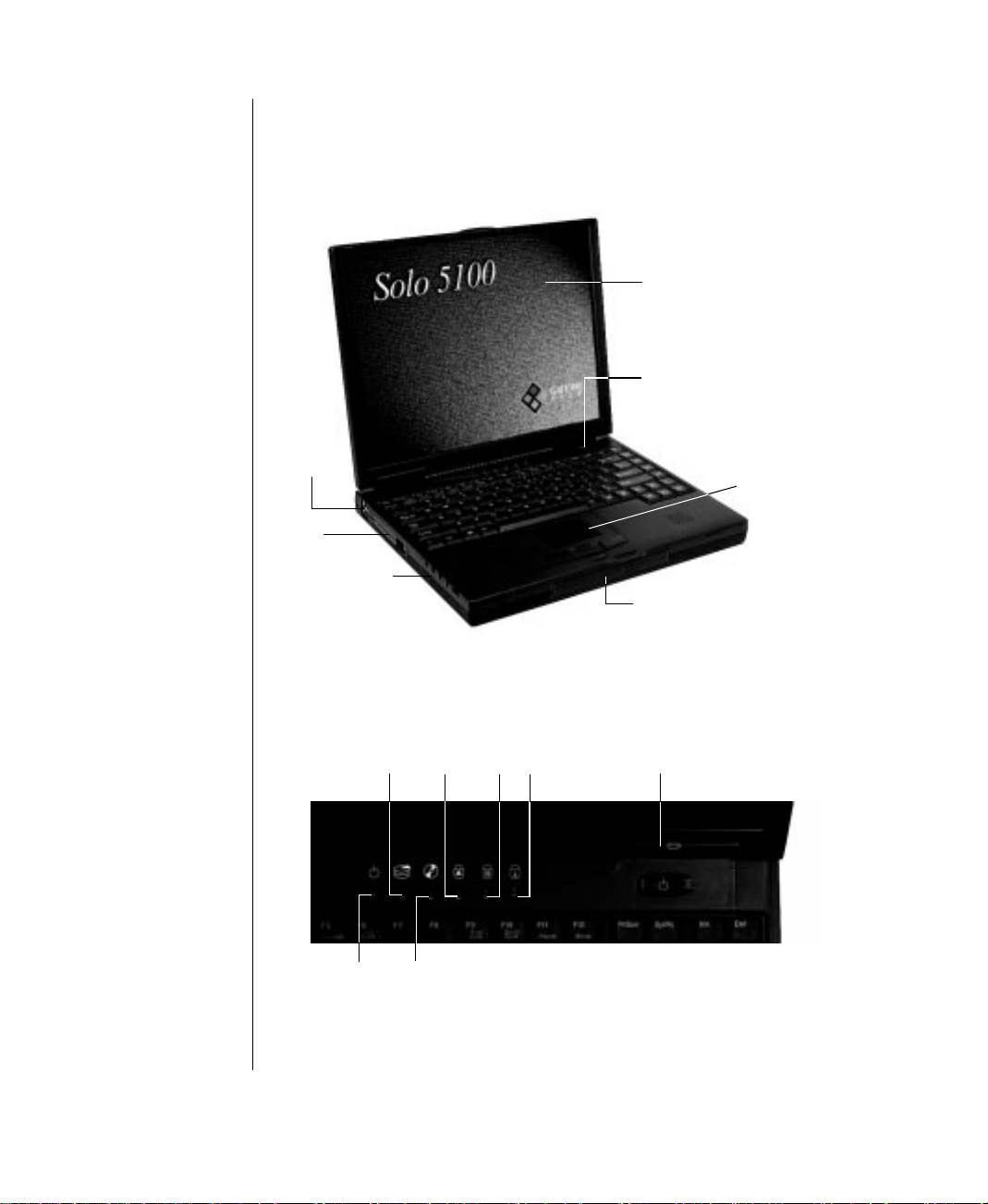
Checking Out Your System
T ake a quick tour of your noteb ook to familiarize yourself with the options
available.
Color LCD
display
Power
button
USB
Ports
PC Card
slots
Audio
Ports
Ke yboar d and LCD panel
Hard disk drive
access
indicator
Power
indicator
Modular option bay access
indicator (CD-ROM /
Floppy disk drive
System indicator LEDs
Cap
lock
Pad
lock
Scroll
lock
EZ Pad Plus
pointing
device with
scroll switch
Modular option
bay (CD-ROM or
Floppy disk drive)
Battery
charge
indicator
8
Your Solo 5100 Multimedia Notebook
Usin
Page 10
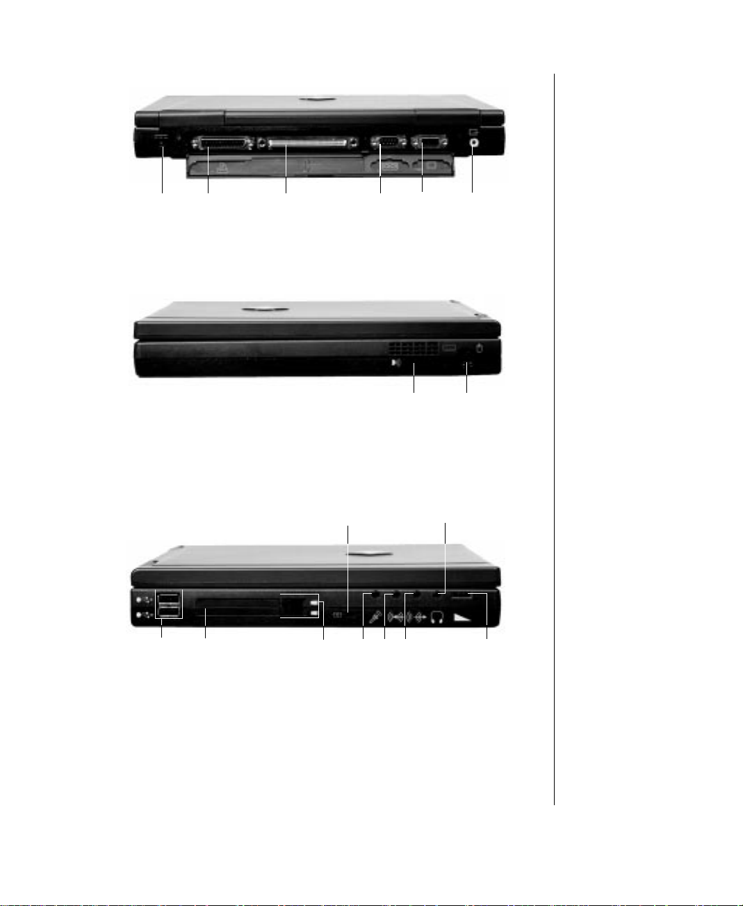
Power
connector
Parallel
port
Back ports panel
Docking
station port
Serial
port
VGA
port
Composite
video out
Right side ports
USB
ports
PC Card
slots
PC Card
eject
buttons
Left side ports and PC Card slots
Kensington
lock
Mic
Fast IR
port
Speaker out/
Headphone jack
Line
Line
in
out
PS/2 port
Volume
wheel
Chapter 1: Checking Out Your System 9
Page 11
g
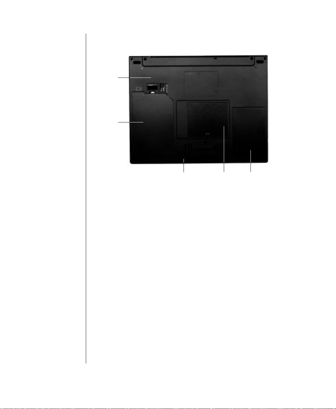
Battery
bay
release
latch
Battery
bay
Modular
option bay
release latch
Bottom release latc hes and memory bay
Memory
bay
Hard
drive
bay
10
Your Solo 5100 Multimedia Notebook
Usin
Page 12

Chapter 2:
Getting Started
Contents
Getting Started....................................................... 12
Connecting AC power.................................... 12
Powering up your notebook........................... 13
LCD Display................................................... 15
Keyboard.........................................................16
EZ Pad Plus Pointing Device......................... 22
Windows 95.................................................... 23
Page 13
g
Getting Started
The best way to get familiar with your ne w notebook is to start ex ploring. This
chapter tells you some of the things you may want to know first such as How do I
turn it on?, What do those lights mean?, and Where do I f ind out more?
T o do that explo ring, you will need pow er - the power that co mes from either the
electrical outlet (AC po wer) or from the battery. We suggest that you use the A C
power first to allo w your battery to get a fu ll charge. Sometimes softw are
applications will act strangely if the battery charge is lo w .
Connecting AC power
Your notebook is powered by one of the longest-lasting batteries availab le and was
shipped to you partially charged, ready to use. You might, howe ver , wa nt to use the
AC adapter to fully c harge the battery and provide a consta nt supply of power
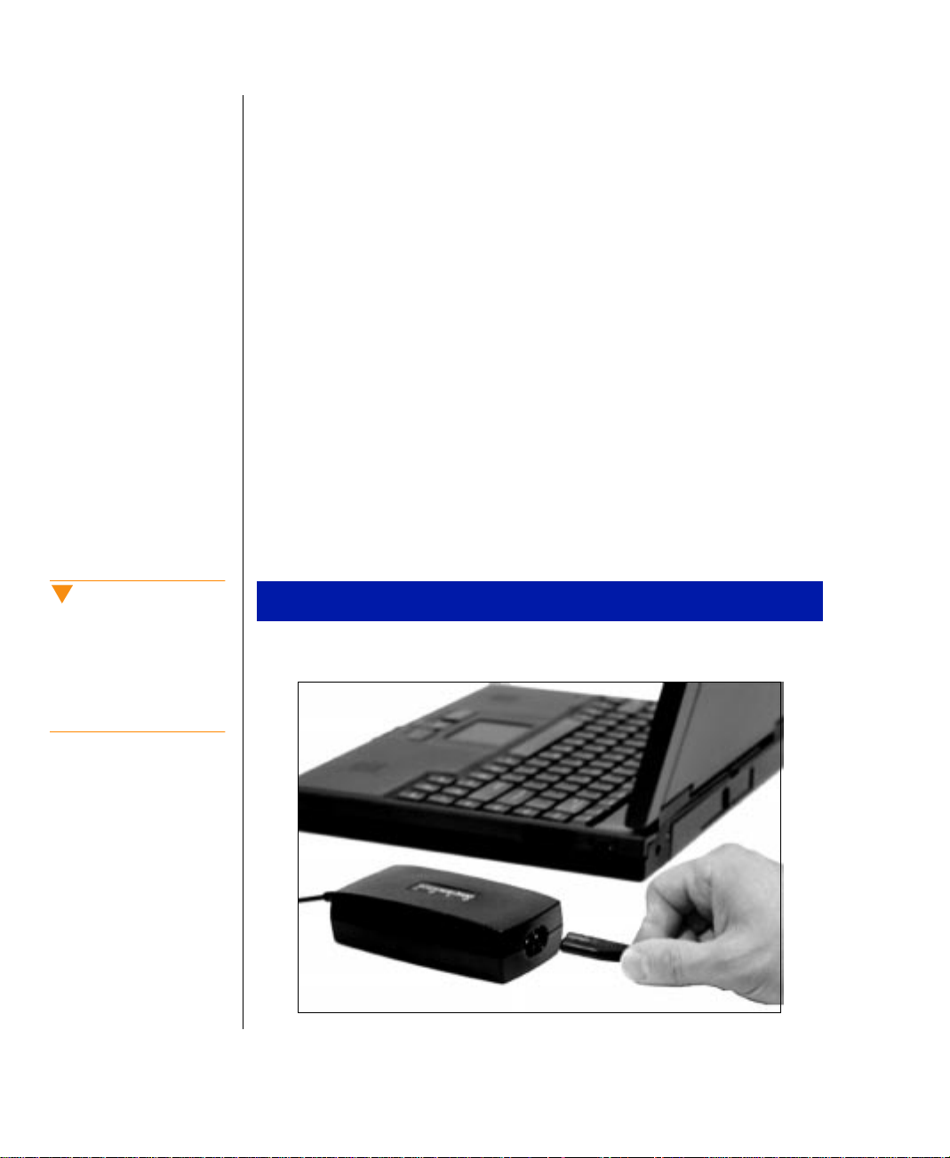
while you are checking out some of the features. Your AC adapter comes as two
parts: a power cord with a plug at one end and a flat connector at the other; and a
cord with the adapter “block.” Connect the flat end of the cord to the adapter block,
connect the post end of the cord to your notebook, and the n the wall plug.
Caution!
Replace the power cord if it
becomes damaged. The
replacement cord must be
of the same type and
voltage rating as the
original cord.
12
Your Solo 5100 Multimedia Notebook
Usin
To connect the AC adapter
1.
Connect the power cord to the A C adapter “block”.
Page 14
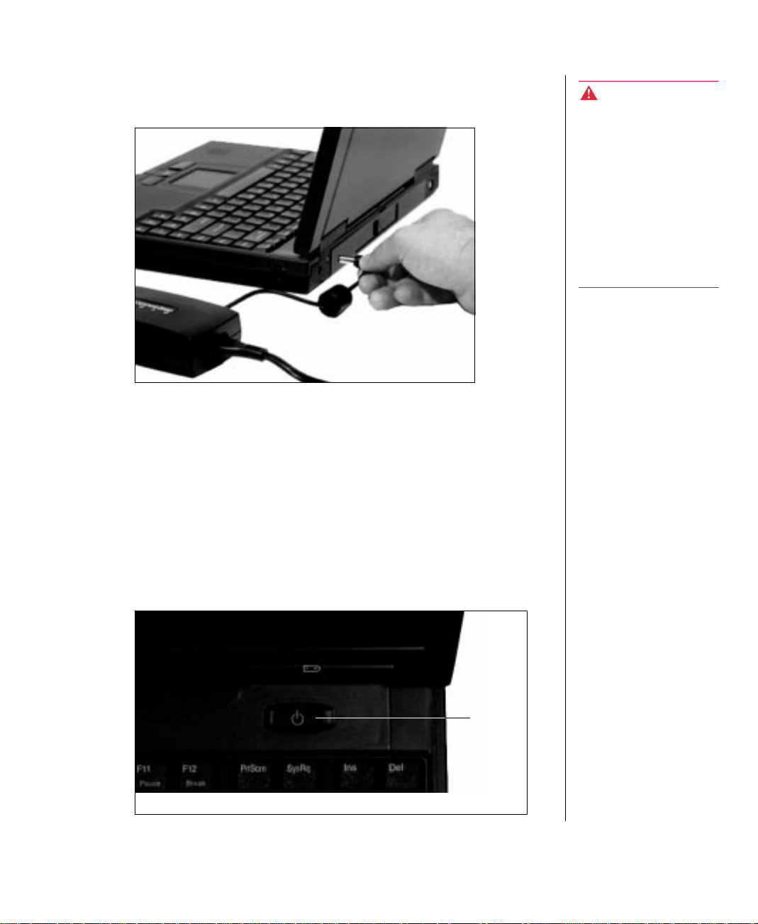
2.
Plug the AC adapter into your notebook's power con nector , located at the
back of your notebook near the right side.
3.
Plug the power cord into an electrical outlet.
P owering up your notebook
Press in on the latch on the front face o f your notebook to release the Liquid Crystal
Display (LCD) lid, and lift to open. T o turn on your notebook, press the po wer
button, located in the upper right corner abo ve the k eyboard.
Warning!
Do not attempt to
disassemble the A C
adapter. The AC adapter
has no user-replaceable or
user-serviceable parts
inside. The AC adapter
controls dangerous
voltages that can cause
serious personal injury or
death. Contact Gateway
about returning defective
AC adapters.
The power b utton on your system is preset in On /Off mode. Ho wev er , you can set it
to function either in On/Off or Suspend/Resu me mode using the setup screens (se e
“Power menu” on page 57).
Power
button
Chapter 2: Getting Started 13
Page 15
g
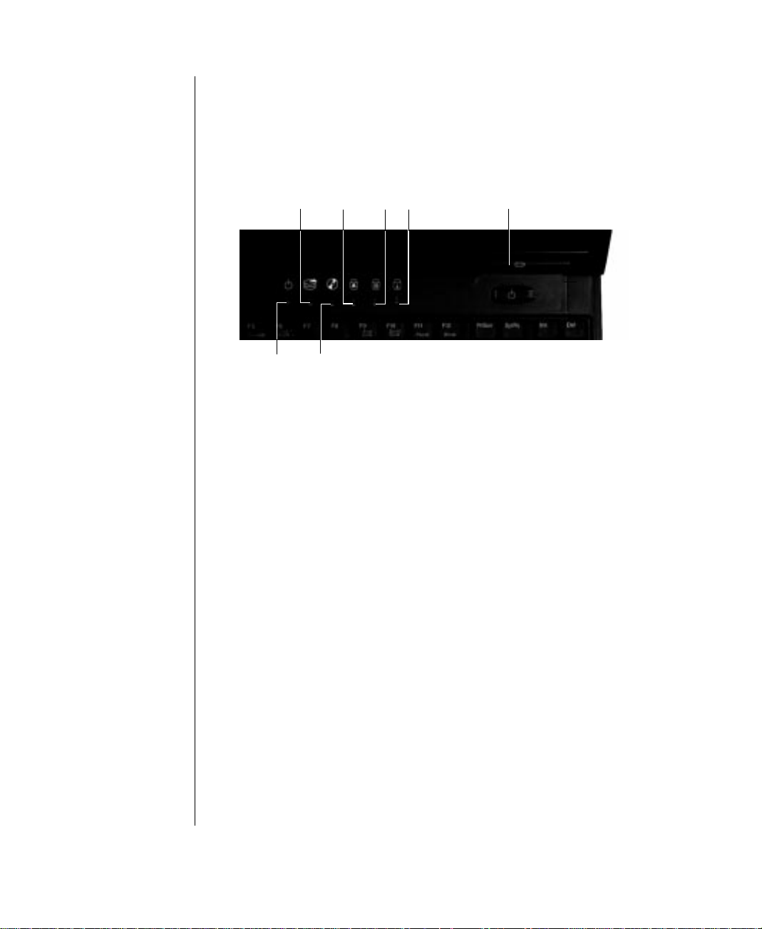
System Status Indicators (LEDs)
The notebook status and various system modes are indicated b y the system
indicators. Following is a description of the indicators and what each means.
Hard disk drive
access
indicator
Power
indicator
♦
Hard disk drive access light indicates that the hard driv e is in use.
♦
Cap lock indicates that the caps lock is on. When the caps lock light is on, you
Cap
Pad
lock
Scroll
lock
lock
Modular option bay access
indicator (CD-ROM /
Floppy disk drive
Battery
charge
indicator
type in all capital letters.
♦
Pad lock indicates that the pad lock is on. When the pad lock light is o n, you
can access the embedded numeric keypad.
♦
Scroll lock indicates that the scroll lock is on. When the scroll lock light is o n,
you can scroll through large v olumes of text in some programs.
♦
Battery charge indicator has four modes of indication:
14
♦
♦
Your Solo 5100 Multimedia Notebook
Usin
Green LED indicates the battery is fully char ged
•
Yellow LED indicates the battery is charging
•
Red LED indicates a battery charging circuit malfunction
•
LED off indicates the A C adapter is not connected to the notebook
•
Power LED indicates that the system is on; the po wer indicator LED glows
green if the CPU is being actively utilized, yello w CPU if utilization is lo w ,
and red if there is a problem with the processor . A red LED is highly unusual;
if it remains red after rebooting the system, contact technical support.
Modular option bay access indicator (CD-ROM or Floppy disk driv e)
indicates that the CD-ROM or the flopp y driv e is in use.
Page 16
LCD Display
Your notebook features a built-in, backlit, color Liquid Crystal Display (LCD).
Each XGA display provides sharp, crisp re solution with an anti-glare scre en.
Tilt your notebook's co ver forward or backw ard to adjust the view ing angle. Press
the <Fn> key together with the <Up Arro w> or <Do wn Arrow> k eys to control
display brightness.
Note:
Some screens may ha v e a
small number of colored
dots when viewed in the
“Black” mode. This is
normal and does not affect
the overall scre en image .
Chapter 2: Getting Started 15
Page 17
g
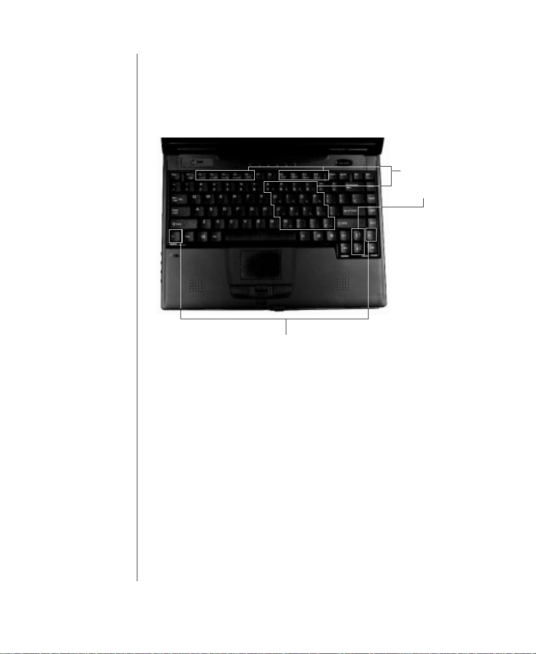
Ke yboard
Your notebook features a full-size keyboard. T o provide the full functionality of a
desktop computer keyboard, man y of these keys ha ve been assign ed alternate
functions, including shortcut key s for W indows 95 and Status Disp lay menus.
Fn keys for
function key
combination
Function keys
16
For normal key functions:
♦
♦
Your Solo 5100 Multimedia Notebook
Usin
Press the key alone to get standard lower case letters, n umerals and
punctuation marks.
Press the key together with the <Shift> ke y to get standard upper case letters
and symbols.
Page 18
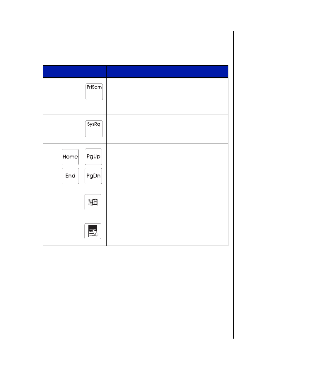
Special keys
The following keys help you a ccomplish shortcuts when wo rking with some
software:
Key Description
Will print the screen if an external printer is connected to your notebook (DOS only). In Windows
95 this key combination puts the screen content
into the clipboard. You can then paste it into a
program such as Paint to display or print it.
System Request is reserved for certain applications such as some DOS programs.
Some software use these keys to help you
quickly navigate through the software, documents or other functions. Reference the software
manual to determine how the keys function with
the software.
Use this key to display the Windows Start menu.
Use this key to provide quick access to shortcut
menus and help assistants in Windows.
Chapter 2: Getting Started 17
Page 19
g
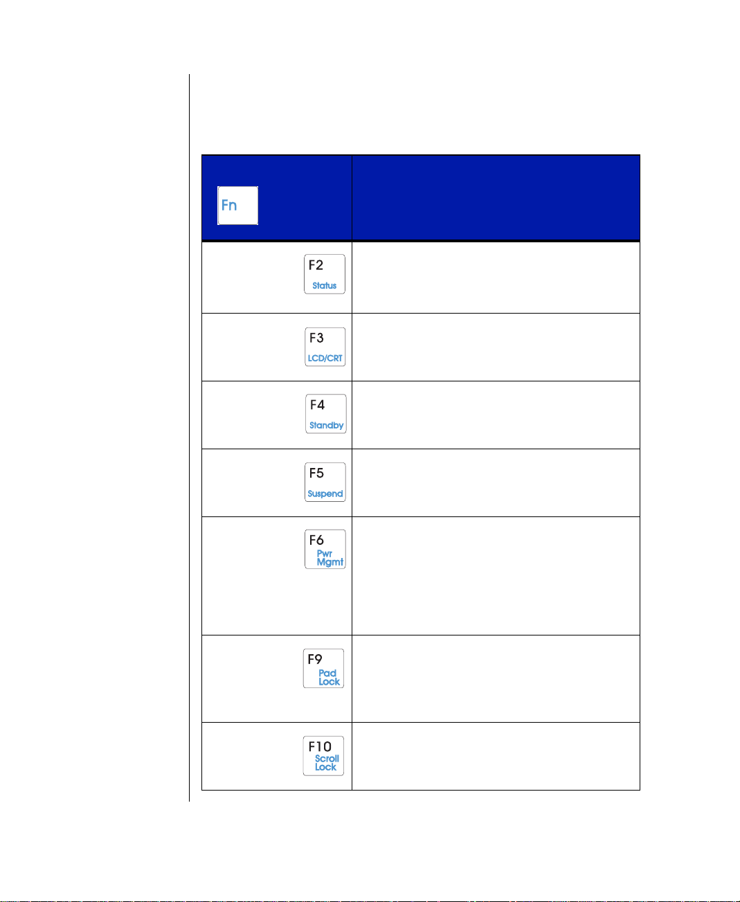
Function keys
Press the <Fn> key together with one of the following ke ys (with blue letters) to get
these specific functions:
Key Combination Description
+
Displays the power status display for the Popup
Status Display program in the upper left corner of
the desktop. Press the key combination again to
make the display disappear.
Toggles between the LCD display, external monitor, both displays at the same time , or NTSC/PAL
as the active display.
Places the system in Standby mode. Press any
button or key on the keyboard to resume using
your notebook.
Places the system in Suspend mode. Press the
power button to resume power to the notebook.
18
Your Solo 5100 Multimedia Notebook
Usin
Makes temporary changes to the power management (PM) mode settings by toggling the settings
from Savings, Perform, Disabled, and Custom.
The changed setting is displayed each time the
button is pressed. To view the settings without
changes, use the Fn+F2 combination. After
about 30 seconds, the display disappears.
Enables the Pad Lock function, so you can
access the embedded numeric keypad. The Pad
Lock LED stays lit while this function is enabled.
Press the key combination again to make the display disappear.
In some programs you can scroll through large
volumes of text. The Scroll Lock LED stays lit as
long as this function is enabled.
Page 20
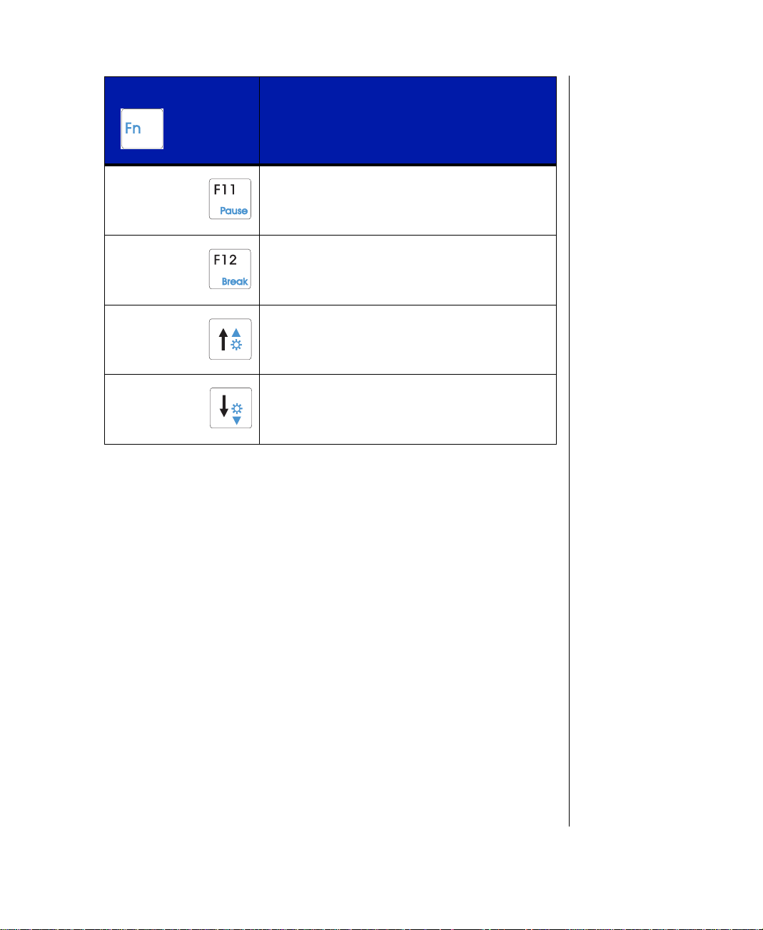
Key Combination Description
+
In some programs this key combination pauses
the display when text is scrolling very quickly.
Press any key to restart the text flow.
In some programs this key combination breaks
the text.
Increases LCD brightness when the key combination is pressed repeatedly.
Decreases LCD brightness when the key combination is pressed repeatedly.
Chapter 2: Getting Started 19
Page 21
g
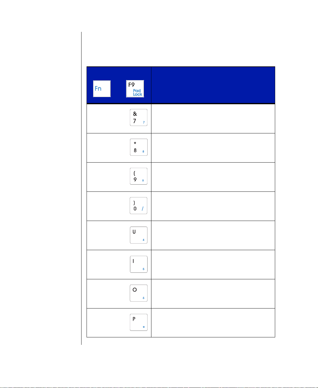
Pad Lock Keys
Press the <Fn> and <Pad Lock> key s together , together with one of the follo wing
keys to activ ate the numeric k eypad:
Key Combination Description
+
Pressing the 7 key produces a 7 when the Pad
Lock function is enabled.
Pressing the 8 key produces an 8 when the Pad
Lock function is enabled.
Pressing the 9 key produces a 9 when the Pad
Lock function is enabled.
Pressing the 0 key produces a / when the Pad
Lock function is enabled.
20
Your Solo 5100 Multimedia Notebook
Usin
Pressing the U key produces a 4 when the Pad
Lock function is enabled.
Pressing the I key produces a 5 when the Pad
Lock function is enabled.
Pressing the O key produces a 6 when the Pad
Lock function is enabled.
Pressing the P key produces an * when the Pad
Lock function is enabled.
Page 22
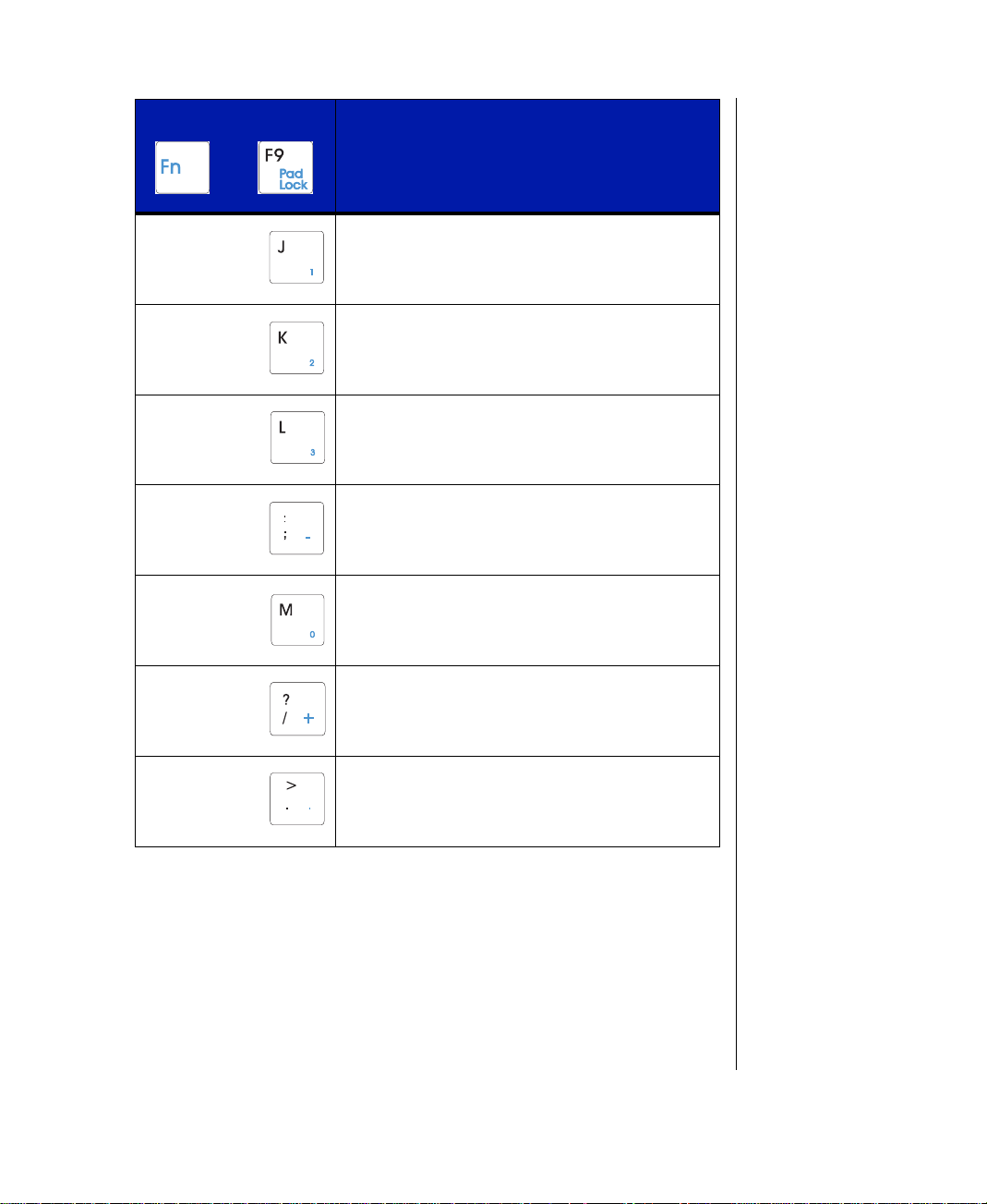
Key Combination Description
+
Pressing the J key produces a 1 when the Pad
Lock function is enabled.
Pressing the K key produces a 2 when the Pad
Lock function is enabled.
Pressing the L key produces a 3 when the Pad
Lock function is enabled.
Pressing the ; key produces a - when the Pad
Lock function is enabled.
Pressing the M key produces a 0 when the Pad
Lock function is enabled.
Pressing the / key produces a + when the Pad
Lock function is enabled.
Pressing the . key produces a . when the Pad
Lock function is enabled.
Chapter 2: Getting Started 21
Page 23

g
Caution!
Do not use a pen or pencil,
only your fingertip, on the
EZ Pad Plus pad.
EZ P ad Plus Pointing Device
Like a mouse, the EZ Pad Plus pointing de vice controls the movements of the cursor
on the screen. Press a finger lightly against the pad, then slide it in the direction you
want the cursor to move. Use the b uttons or tap on the pad to select something.
EZ Pad Plus
Touchpad
buttons
Rocker
switch
You can use the EZ Pad Plus rocker switch while using some Microsoft programs
(e.g. W ord, Excel, Internet Explorer) to scroll through a doc ument in addition to the
traditional point and click:
T o scroll:
♦
Press forward or backward on the rocker switch to scroll through documents,
similar to using traditional scroll bars.
To click:
♦
Position the cursor on the item and press the left button once.
or
♦
Position the cursor on the item and tap on the pad once.
T o double -click:
♦
Position the cursor on the item and press the left button twice.
or
♦
Position the cursor on the item and tap on the pad twice.
22
Your Solo 5100 Multimedia Notebook
Usin
Page 24

T o drag and dr op:
g
♦
Position the cursor on the item and hold down the left b utton while sliding
your finger to reposition the cursor , then release the button.
or
♦
Position the cursor on the item and tap on the pad twice; after the second tap,
hold and slide (without lifting your finger) to reposition th e cursor , then lift
your finger to release.
Customizing the EZ P ad Plus
You can customize the EZ Pad Plus to work the way you want when you set button
configuration, drag, edge motion, o r cursor’ s speed, rate, a nd size.
To customize the EZ Pad Plus
1.
Click on Start, Settin
icon.
2.
Click on each of the different tabs to see th e options av ailable.
You also can attach an external mouse to the notebook through the PS/2 port on the
right side of the notebook or the USB ports if the mouse is USB compatible. The
optional docking station solutions also offer ports fo r external mouse connections .
It is not necessary to shut down the system when co nnecting an extern al mouse. To
use some external pointing de vices, you may need to disable the EZ Pad Plus.
s and Control Panel. Doub le-click on the Mouse
W indows 95
Your notebook is pre-loaded with the Windows 95 operating system software and
other programs that you ordered. Once you turn on your system, the W elco me to
Windo ws 95 screen appears on the display .
Chapter 2: Getting Started 23
Page 25

g
This screen provides a Wind ows tour , information about what's ne w, the
g
g
opportunity to register your software online, info rmation about W indo ws products
and useful tips.
Click the Windows Tour button to start a brief tour of the operating syste m. This
tour provides information on starting a program, e xploring your disk, f inding a file,
switching windows, and using Help . Click on the button ne xt to the topic that you
are interested in, then follow the screen prompts. If y ou have an y questions about
the instructions, click on the Show Me button. Clic k on the Exit button and
follow any screen prompts (when you are finished).
Click on What’s New for information more experie nced users might f ind useful.
This screen gives an o verview of changes between earlier versions of W indows and
Windo ws 95. Click on the box ne xt to the topic you are interested in . Click on the X
in the upper right corner of the window to close the scree n.
24
Click on the Online Re
free number. You will need a modem to access this option.
Click on
purchase. Y o u must load the W indows 95 CD-ROM in the CD-ROM module to
access this option.
Clicking
know ... section of the Welcome to Windows 95 screen.
Click on either the
W elcome screen to close it, an d start using W indows 95.
Your Solo 5100 Multimedia Notebook
Usin
Product Catalo
Next Tip
provides operational tips, which are displayed in the Did you
Close
istration button to register your software usin g a toll-
to see what other Windo ws options are available for
button, or the X in the upper right corner of the
Page 26

Start button
The Start button is located in the bottom left corner of the Windo ws 95 desktop
and accesses the Start menu. Most programs and applications are launched via the
Start menu. T o access the menu, click on the Start b utton or press one of
the keys, located on either side of the Alt keys next to the spacebar .
Taskbar
The taskbar is located along the bottom of the W indow s 95 desktop. The task bar
contains the start button in the left corner and displays all activ e/running programs.
If a program has been minimized, click on the program name in the taskba r to
restore it.
If you need additional help:
If you have additional questions, check th e online documentation or a printed
manual. For online documentation, check the Help option in each software
package. The Windo ws 95 manua l you receiv ed with your notebook is a reference
for Windows 95 questions.
If you purchased your notebook in the US, you can order other printed manu als at
an additional cost through the Document Offer Program. Order forms are included
in the information pack that came with your system software CDs.
Chapter 2: Getting Started 25
Page 27

26
g
Your Solo 5100 Multimedia Notebook
Usin
Page 28

Chapter 3:
Using Your System
Contents
Using Your System ............................................... 28
Battery Pack Bay............................................ 28
Option Bay...................................................... 30
Swapping modules.........................................31
External Floppy Disk Drive........................... 32
Removing and replacing the hard drive......... 32
Playing an Audio CD..................................... 35
Built-in audio features.................................... 37
PC Cards.........................................................43
About CardBus............................................... 44
Page 29

g
Using Your System
Swapping batteries, the CD-R OM module, the floppy d isk driv e module, hard
drives, and PC Cards (such as modems) are e very-day tasks that are easily
accomplished on your notebook. This chapter ex plains how to swap these modules
and how to use them to play CD-R OMs, mak e an audio recording, and conn ect the
PC Cards.
Battery P ack Bay
Battery packs can be “warm-swapped” in the ba ttery bay . This means you c an
change battery packs while in Suspend mode.
Warning!
There is a danger of
explosion if an old, w ornout battery is incorrectly
replaced. Replace only with
the same or equivalent type
recommended by the
manufacturer. Dispose of
used batteries according to
the manufacturer’s
instructions included with
the new battery packaging.
To remove the battery pack
1.
Save all work.
2.
Press the <Fn> key together with the <F5> (Sus pend) key to put the system
into suspend mode.
3.
Close the cover and turn your notebo ok over.
4.
Slide the battery release latch back to release the battery .
28
Your Solo 5100 Multimedia Notebook
Usin
Page 30

5.
Hold the latch back and lift the battery up out of the battery opening .
To replace the battery pack
1.
Place the battery pack into the battery bay , pushing downwa rd until it “snaps”
into place.
2.
Turn the notebook right sid e up and open the cov er .
3.
Press the power button (quick press and release) to resume po wer to the
system.
Chapter 3: Using Your System 29
Page 31

g
Option Bay
The Gateway Solo 5100 Multimedia Notebook features a modular op tion bay
located in the front panel of the notebook. This bay accepts the CD-ROM module
or the floppy disk driv e module.
30
T o use CD-R OM and floppy disk dri ve functions simultaneously, first install the
modular CD-ROM dri ve into yo ur notebook. Connect an e xternal floppy dri ve to
the parallel port at the back of your notebook using the optional ada pter cable.
Your Solo 5100 Multimedia Notebook
Usin
Modular option bay
Page 32

Swapping modules
The CD-ROM module can be e xchanged for the flopp y disk driv e module in the
modular option bay . Each time you change them o ut, howe ver , you must rebo ot
your system.
To switch between CD-ROM and floppy disk drive modules
1.
Save all work, then follo w your operating system’ s
Shut Down
to turn it off.
2.
Close the cover and turn your notebo ok over.
3.
Locate the modular bay access latch. Slide the latch open and use the grip
near the front of the notebook to pull the CD-R OM module out of the
notebook.
.
procedure
Note:
Be sure to save and exit
any applications before
initiating any of the
following procedures.
Chapter 3: Using Your System 31
Page 33

g
4.
Turn your noteboo k back ove r and install the floppy disk dri ve mo dule.
5.
Firmly push the floppy disk driv e module straight into the bay until the latch
“clicks” into place and is firmly seated. If you don't hear the “clic k,” try it
again.
32
External Floppy Disk Drive
Your floppy disk drive module can be used as an external dri ve b y using the
optional adapter cable to connect to the parallel port at the back of your noteb ook.
You can then have a CD-ROM in the modular option bay and ha ve the u se of the
floppy disk drive, which normally resides in the modular option bay. It is not
necessary to reboot the system for it to recognize the connection.
Removing and r eplacing the hard drive
You can remove your notebook's hard disk drive (HDD) from your no tebook for
replacement, or to switch between optional additional hard dri ves.
Your Solo 5100 Multimedia Notebook
Usin
Page 34

To remove and replace the hard disk drive
1.
Save all work.
2.
Use your operating system’ s Shut Down procedure to turn yo ur notebook
completely off.
3.
Close the LCD lid.
4.
Disconnect the AC po wer (if plugged in to the notebook).
5.
Turn your notebook o ver and locate the hard driv e latch.
6.
Unscrew the hard driv e retaining scre w .
Chapter 3: Using Your System 33
Page 35

g
7.
Gently pry the hard drive latch up an d out of the seated position. Slide the
hard drive forw ard and lift it out of the hard dri ve tray .
8.
Place the new hard driv e into the hard dri ve tray; slide it back into p osition so
that the connector plug is firmly seated into the dri ve ’ s plug-in.
34
9.
Your Solo 5100 Multimedia Notebook
Usin
Seat the latch down into position and secure with the sc rew. Then turn your
notebook back over and reconnect the AC po wer (if necessary).
Page 36

Playing an Audio CD
Your notebook contains all the key features needed to enjoy your fa vorite audio
CDs.
To play an audio CD
1.
Make sure the CD-ROM mo dule is installed in the modular option bay.
Note:
Power (either battery or AC)
must be supplied to your
notebook before y ou can
open the CD-ROM tray.
Volume
wheel
CD-ROM
module
2.
Press the Eject button on the front of the CD-R OM module.
3.
Gently pull the CD-ROM tray fully ope n and place the audio CD into the
Eject
button
CD-ROM manual
release — to eject
without power
tray.
4.
Push in the CD-ROM tray until it closes completely.
5.
After a few seconds, the CD-R OM will start playing automatically.
Note:
If power is unav ailab le and
you need to remove a CDROM disk, you ma y
manually eject the CDROM tray using a thin
prodding device such as
the end of a paper clip
inserted into the CD-ROM
manual release hole .
Chapter 3: Using Your System 35
Page 37

g
6.
g
Click on the CD Player option that appears in the taskbar along the bottom of
the display, or click on Start, Pro
rams, Accessories, Multimedia,
and CD Player to access the CD Player screen. You can change music
tracks, view playing times, control th e volume, set prefe rences, define a play
list and even set the system to contin uous or random play through the CD
Player screen.
Click on the CD Play er b utton after it
appears in the Taskbar to display the
CD Player windo w on the desktop as
shown below
36
7.
1.
2.
Experiment with the different settings in the CD Player screen to f ind the ones that
work best for you.
Your Solo 5100 Multimedia Notebook
Usin
Slide the mouse pointer slowly ov er the control buttons on the CD Player
screen to display the function of each bu tton.
To remove a CD
Click on the Eject button in the CD Player scre en, or press the eject bu tton
on the front of the CD-RO M drive whe n you hav e finished listening .
Gently pull the CD-ROM tray fully ope n and remov e the CD; then close the
tray .
Page 38

Built-in audio featur es
g
p
Speakers and internal micr ophone
This system contains a built-in microphone and stereo sp eakers.
T o control the v olume:
♦
Use the Volume wheel located on the side of your notebook. Rotating it
towards the back increases the volume while rotating it forward decreases the
volume.
♦
Or, click on
Multimedia
♦
Or, click on the speaker ic on in the lower right corne r of the taskbar . A volu me
control screen will appear . Using the EZ Pad Plus pad, slid e the pointer up or
down to change the v olume setting. Click once anywhere on th e Win dows 95
desktop to close the screen.
♦
Or, double-click on the speak er icon in the lo wer right corner of the taskbar . A
more detailed volume control screen will appear , containin g volume and
balance controls for master volume control, wa ve, CD audio and 3D
Enhancement settings. Using the EZ Pad Plus pad, slide the pointers to the left
or right to control balance, or up or down to change the v olume setting.
Start, Settin
icon. You can change the volume from the
and
s
Control Panel
. Double click on the
Audio tab
.
T o adjust the 3D Enhancement settings, first make sure
checked on the
settings.
Use the audio ports on the left side of your notebook, or the audio ports on the
optional docking station to add external speakers, headphones or a microphone.
O
tions Menu
, then click on the Advanced box to c hange the
Advanced Controls
Playing a MIDI file
The notebook has two musical instruments capable of pla ying back MIDI files.
These instruments consist of:
♦
A four-operator FM synthesizer with 16 voices. FM synthesis creates complex
sounds by mixing simple wav eforms; it is a primitiv e form of synthesis
included primarily for compatibility with games and entertainment software.
is
Chapter 3: Using Your System 37
Page 39

g
g
Note:
General MIDI is an
extension of the basic MIDI
specification that assigns
specific patch numbers to
specific instruments.
♦
A software wavetable synthesizer , which provides much more realistic MIDI
playback quality using digital samples (recordings) of actual instruments. It
also includes general MIDI compatibility to ensure proper playback of most
MIDI files.
You can choose to use either FM or wavetable synthesis when playing back MIDI
files. For best sound quality, we recommend the software wavetable synthesizer.
To select a music synthesizer
1.
Click on Start, Settin
s, Control Panel, and double-clic k on the
Multimedia icon. The Multimedia Properties control panel appears.
2.
Select the tab labeled “MIDI.” The MIDI control panel appears:
38
Your Solo 5100 Multimedia Notebook
Usin
Select Midi for Internal ESS Software W avetable if you want the
software wavetable synthesizer . You can play back most .MID or .RMI MIDI
files with the Media Player accessory supplied with W indo ws 95. If you want
to create and edit MIDI files, consider purchasing a commercially av ailable
MIDI sequencer software application available from software retailers or
music stores.
3.
Click on OK when you are finished selecting a music synthesizer.
Page 40

g
To play back a MIDI file
1.
Click on Start, Pro
Media Player icon. The Media Player appears on the display.
2.
From the File menu, select Open. A list of sample files supplied with
Windo ws 95 appears; click on the Files of type d rop down box to select
MIDI Sequencer file types. This will show o nly MIDI type files.
rams, Accessories, Multimedia, and click on the
Double-click on the file of your choice, then click on the (Play) button in
Media Player. The seq uence should begin playing . If you can't hear it, make
sure that the volume control wheel on the side of the notebook is tu rned up.
If you hear a strange rhythmic pattern played by a non-percussion instrument
when playing back a MIDI file, the percussion instrument chann el is
probably set incorrectly . It is generally accepted that percussion instruments
should go on MIDI channel 10, and this is the default setting for W indo ws 95.
Howev er , you may encounter a MIDI f ile that plays percussion in struments
on channel 16 instead. Playing back such a file with the softw are wa vetable
Chapter 3: Using Your System 39
Page 41

g
synthesizer default channel 10 percussion setting creates bizarre effects, such
as a snare drum or cymbal part played back on an electric piano, and a bass
drum on a flute.
To correct this wavetable synthesizer channel:
1.
Click the “ Adv anced” tab in the Multimedia Control P anel to bring up the list
of multimedia devices installed on your system. Click the + beside MIDI
Devices and Instruments.
40
2.
3.
Your Solo 5100 Multimedia Notebook
Usin
Double-click on the instrument MIDI for Internal ESS Software
Wavetable.
Click on the “Details” tab.
Page 42

4.
Click on the Percussion on Channel 16 option, click Apply , then clic k
on OK.
5.
Try playing the sequence again . This time, the percussion instruments sho uld
play correctly .
When you're finished playing this f ile, be sure to set this control pa nel option back
to “General MIDI Instrument,” or you'll encounter the same problem wh en trying
to play back a normal MIDI file with percussion instruments on MIDI channel 10.
Playing external MIDI modules or ke yboards
You can use a MIDI sequencer on your notebook to play through external MIDI
modules or keyboards. To do this, you need one of the optional Solo docking
solutions that has a MIDI/Game port. You also need a standard MIDI connector
that converts the Game port co nnector to standard 5-pin MIDI In and Out
connectors. The connector is av ailable from v arious musical instrument retailers.
Chapter 3: Using Your System 41
Page 43

g
Making an Audio Recor ding
g
g
Note:
Connecting an external
microphone will disable the
built-in microphone.
Use the built-in microphone, or connect an e xternal microphone using the Mic p ort
on the left side of your notebook to make an audio record ing.
.
Mic
To make an audio recording
1.
Click on Start, Pro
Recorder to access the Sound Recorder screen.
2.
Click on Edit and Audio Properties to set/check record volume le vels.
3.
Click on File and New to begin a recording.
4.
Slide the mouse pointer slowly ov er the control bu ttons along the bottom of
the screen to display the function of each butto n.
rams, Accessories, Multimedia, then Sound
42
5.
6.
7.
You can play back the recording in either Sound Recorder, or Media Player.
1.
2.
3.
Your Solo 5100 Multimedia Notebook
Usin
Click on the ● (Record) button to start reco rding.
Click on the ■ (Stop) button to end record ing.
Click on File and Save As... to name and store the recording.
To play back the recording in Media Player
Click on Start, Pro
Player to access the Media Player screen.
Click on File, then Open....
Select the file to play back and click the Open button.
rams, Accessories, Multimedia, then Media
Page 44

4.
Slide the mouse pointer slowly ov er the control buttons along the bo ttom of
the screen to display the function of each button.
5.
Click on the (Play) button to start the playback.
6.
Click on the ■ (Stop) button to end playback.
PC Car ds
Your notebook’s PC Card slots (also known as PCMCIA card slots) are located
behind the PC Card doors on the left side of your notebook. These slots accept two
T ype II PC Cards or one Type III card. Y our notebook is pre-con figured to
automatically accept most PC Cards.
To insert a PC Card
1.
Select a PC Card (such as a modem) to insert.
2.
Locate the PC Card slot in which you wish to insert the card. If you are
installing a T ype III PC Card, it must be inserte d into the bottom slot.
PC Card slots
PC Card eject button
Note:
Some PC Cards, such as
Zoomed Video cards, ma y
require additional drivers.
Refer to the PC Card’s
documentation.
Chapter 3: Using Your System 43
Page 45

g
3.
Slide the card into the chosen slot. The f irst time you insert a PC Card, follo w
the installation steps in the Windo ws prompts. When the card is installed
correctly , your notebook emits a two-toned beep. Operate the device as
recommended in the PC Card's manual.
To remove a PC Card
1.
Click on the PC Card icon in the taskbar .
2.
Using your mouse, click on the card that you want to remov e. A screen will
appear stating when it is safe to remove the PC Card. Click on OK.
44
3.
You do not need to reboot your notebook when changing most cards because your
notebook supports “hot-swapping.” This means you can usu ally insert a PC Card
and have it recognized b y the system without shutting do wn your noteboo k or ev en
putting it into Suspend mode. See your PC Card's documentation for further
information.
About Car dBus
The 32-bit CardBus technology (sometimes referred to as “PC Card 32 cards”)
supports DMA and bus mastering technologies that are useful in performa nceintensive applications lik e full-motion video, high spe ed network connections, fullmotion video capture and display , and high performan ce peripheral interfaces.
Your Solo 5100 Multimedia Notebook
Usin
If the folding Eject button is in the recessed position, rota te the button to the
eject position, then press the eject button to remove the card.
Page 46

While not many 32-bit CardBus cards are on the mark et yet, you can use them
interchangeably with 16-bit cards in your notebook. Ho wev er , please note that
some docking solutions do not support CardBus. CardBus cards function only in
your notebook's PC Card slots.
Using a Modem
Installing and using a modem with your notebook is u sually an easy process. If you
have ordered a modem with your notebook, the dri vers for the modem hav e already
been loaded onto your notebook.
The modem may need different adapters depending upon the country in which it is
used. The XJ AC K modem (shown belo w) is av ailable for purchase only in the
United States. European customers may purchase a modem with an external D AA.
To install the TeleP ath data/f ax modem
1.
Using the 15-pin connector: Plug the 15-pin connector end of the modem
cable into the end of the modem. If you hav e trouble plugging it in, turn the
connector over .
.
Caution!
Be sure to wait for the “Safe
to remove” message before
you remove the CardBus
card, or you may crash your
system and lose all your
work.
Caution!
Do not use your modem on
a digital phone line. If you
attempt to use the modem
on a digital line, the
TelePath data/fax modem
has built-in protection, and
thus will not work. Other
modems, however , could be
ruined. Most digital lines
are found in hotels or
businesses with special inhouse phone systems.
Or: (see next page)
Chapter 3: Using Your System 45
Page 47

g
Using the XJA CK: Gently p ush on the end of the jack and release. The jack
will pop out. Plug an RJ-11 connector from abov e into the XJ A CK.
.
2.
Insert the modem face up 68-pin connector first, into the PC Card slot in the
left rear side of the notebook. Press the modem gently, but firmly into the PC
Card slot until it will go no farther . Do not force the modem.
3.
Plug the jack end of the modem cable into the wall jack. If you are u sing an
XJA CK mod em and need a longer cord for your mode m, use an RJ-11
connector and extension telephone c able.
46
4.
Your Solo 5100 Multimedia Notebook
Usin
The modem is now enabled and ready to use.
Page 48

Chapter 4:
Connecting Ports and Peripherals
Contents
Connecting Ports and Peripherals......................... 48
Audio connectors............................................ 48
Composite Video Out port (NTSC)............... 49
USB (Universal Serial Bus) port....................50
Fast IR port ..................................................... 51
External computer monitor............................52
External mouse/keyboard...............................52
Printers............................................................ 53
Page 49

g
Connecting P orts and Peripherals
Your notebook has several ports and a variety of hardware conne ctions, allowing
you to connect to peripheral device s or to other computer systems. The a vailable
ports include parallel port, serial port, audio connectors, video port, d ocking station
port, USB port and the Fast IR port. These allow you to use peripherals such as an
external monitor, e xternal mouse or ke yboard, audio and video equipment,
electronic keyboards, and printers.
The ports on the back of your notebook are cov ered by a two-w ay door: the hinged
flap allows access to all the ports. A specia l sliding panels opening in the hinged
flap allows access just to the docking station port.
Audio connectors
Your notebook comes with four audio connectors on the left side. From the left, the
ports include the microphone (mic), line in, line out, and sp eaker out. All audio
connectors use the standard 1/8” jacks.
48
The microphone port is compatible with monaural electret or dynamic
microphones. When an external microphone is plugge d into this connector , the
built-in omni-directional microphone is automatica lly disabled.
The line in and line out ports are high-impedance audio stereo co nnectors and are
intended for use with similar impedance stereo connectors, lik e those found on
home stereo systems and components. Use the line in connector to record from
another computer, stereo equipment or a VCR. The line out jack is not capable of
driving un-amplified spea kers or headphones, b ut can be used for amplif ied
speakers.
Your Solo 5100 Multimedia Notebook
Usin
Mic
Line in
Line out
Speaker out/
Headphone jack
Page 50

The speaker out jack is a low-impedance amp lified stereo audio outpu t and is
g
intended for use with headphones, small unamplif ied speakers or amplif ied
speakers. This connector can provide up to .5 Watt RMS per channel into an 8 ohm
load.
The volume control wheel on the left side controls th e speaker out port and the
internal speakers. The volume le vel for the other ports is controlled b y the
multimedia software. T o access that control panel, click on Start, Settin
Control Panel. Double click on the Multimedia icon. You can change the
volume from the Audio tab.
s and
Composite V ideo Out port (NTSC)
The Composite V ideo (NTSC) Out port (color coded yello w) allo ws you to display
your notebook's screen on a TV screen by connecting the notebook to the TV or
VCR using a standard video connecting cable. This option is typically used with
large-screen TVs to give demonstrations and presentations.
Composite
video out
T o connect the notebook and TV, plug one end of the cable into the Composite
Video Ou t jack on your notebook and the other e nd into the V ideo In connector on
your television or VCR.
T o view the new display, use the key combinationFn+F3 to switch to NTSC/P AL.
You should see the display on the TV screen only. If the display is distorted, check
to see if the BIOS setting is correct for NTSC or P AL (NTSC is primarily used in
the United States).
For optimal usage, set the notebook's display to 640 by 480 pix els. Because a TV
screen's display is of a lower resolution, lar ge fonts should be selected to maximize
on-screen viewing effecti veness.
Chapter 4: Connecting Ports and Peripherals 49
Page 51

g
g
To change the display resolution
1.
Click on the Monitor icon on the taskbar .
2.
Select the desired resolution (640 by 48 0).
3.
Click on Apply , then on OK.
If the Monitor icon does not appear on your taskbar , right click on the d esktop,
click on Properties and then Settin
s. Check the box that says “Show settings
on taskbar.”
USB (Universal Serial Bus) port
USB is a serial interface that serves as a single-port alternativ e to connecting
devices that traditionally ha ve required the ir own specif ic ports such as printers,
joystick/MIDI devices, scann ers, an external mouse or ke yboard. The USB detects
when devices are added or remo ved, then automatica lly determines what host
resources are needed. The USB makes those resource s, including dri ver software
and bus bandwidth, a vaila ble to the peripheral without an y intervention.
Note:
This section on USB
drivers applies only if
you purchased your
notebook in the United
States and have the
USB drivers on a CD
rather than on a diskette.
50
Your Solo 5100 Multimedia Notebook
Usin
USB ports
Your notebook has two USB ports where two peripheral devices, such as a
keyboard or monitor , can plug direc tly into the notebook. If you ha ve an e xpansion
hub built into an externa l keyboard or monitor , or if y ou have a stan d-alone USB
box, you can connect ev en more peripherals (currently up to 127 dif ferent de vices)
at the same time.
Examples of common devices that connect to the USB (b ut must be USB
compatible) include keyboards, jo ysticks, mice and peripherals such as teleph ones,
modems, printers, microphones, digital speakers, scann ers, digital cameras and
game controllers.
Page 52

Your notebook shipped with the USB ports enabled, however , you must load the
peripheral's drivers accord ing to instructions from the USB de vice manufa cturer .
F ast IR port
The Fast IR (infrared) port built in your notebook and a transfer mod ule (optional)
use infrared technology to send signals between the notebook and a remote system.
The IR port is located on the right side of your notebook. It can send as well as
receive signals. A v ariety of desktop computers, printers and other peripherals are
IR-compatible.
Fast IR port
Placing your notebook's IR port within about three feet (or one meter) of another
unit's IR port (and using transfer software) allo ws you to send to or recei ve
information from that remote desktop computer , printer or other peripheral.
The optional transfer module (recei ver/transmitter) must be pla ced no farther a way
than about three feet (or one meter), with the module's IR port directly f acing your
notebook's IR port. The other end connects to the remote system's serial po rt.
Your notebook is shipped with the Fast IR port; however , it mu st be enabled before
using.
Using the F ast IR P ort
T o use the Fast IR Port option, first check in the Control Panel for the Infrare d icon.
If you don't see the icon, infrared support needs to be installed.
In Windo ws 95, double click on the In frared icon in the Control Pane l to get to the
Infrared Monitor window . Click on the Options tab (with Infrared enabled) to
make changes.
Windo ws 95 creates two virtual ports that IR devices use: usually LPT3 for printers
and COM4 for serial transfers. This can be verified by checking the settings in the
Infrared Monitor program. If you wish to install an IR printer, make sure it is set up
Chapter 4: Connecting Ports and Peripherals 51
Page 53

g
on the LPT3 port. T o transfer f iles, use serial or wireless tran sfers on COM4. If fast
IR drivers are installed b ut you are ha ving communication problems, try cha nging
the “Limit connection speed to” setting to 115.2kps.
External computer monitor
Connect an external computer monitor to yo ur notebook through the VGA port on
the back of your notebook or the VGA port on th e optional mini-docking station.
Press the Fn key with the F3 (LCD/CR T) k ey to toggle betwe en activ e displays.
Depending upon the external mon itor, you might hav e to lower the v ideo resolution
to 640 X 480, toggle the video to the e xternal monitor only, or do both.
Parallel port
VGA port
External mouse/ke yboard
Connect an external mouse or ke yboard through the PS/2 port on the right side o f
your notebook, or the PS/2 (keyboard) port on the o ptional docking station
solution. It is not necessary to reboot your system. If the mouse or ke yboard are
USB compatible and the USB driv ers are loaded, they can be connected using the
USB ports.
PS/2 port
52
Your Solo 5100 Multimedia Notebook
Usin
Page 54

Printers
g
Windo ws 95 allows you to co nnect to most brand name printers. After you c onnect
the printer cable to the appropriate port (parallel or USB) on your noteboo k, you
need to set it up using the Add Printer W izard.
To add a printer
1.
Click Start, Settin
2.
Double-click on the Add Printer icon, then follow the instructions from the
Add Printer Wizard.
s, then Printers.
Chapter 4: Connecting Ports and Peripherals 53
Page 55

54
g
Your Solo 5100 Multimedia Notebook
Usin
Page 56

Chapter 5:
Managing Power Consumption
Contents
Managing Power Consumption............................56
Batteries..........................................................56
Power menu.................................................... 57
Page 57

g
Managing Power Consumption
A battery-powered session for your notebook is a ffected b y many things such as
using screen savers rather than the suspe nd function, or playing music CD-R OMs
while using a word processor. If there is no AC po wer outlet nearby, you will want
to make the battery-powered session last as long as possible. This chapter tells you
how to extend the battery-po wered se ssion time by using the following tips or b y
changing the power settings in the Po wer menu.
Some quick tips about conserving battery po wer include:
♦
If you tend to startup and shutdown se veral times on one b attery charge, u se
Suspend instead. Using Resume instead of starting up takes less po wer .
♦
Remove PC Cards when not in use.
♦
Set battery for maximum battery performance in Settings (see discussion
below).
♦
Dim the display as low as is comfortable.
Batteries
The battery must be installed in the notebook and connected to an A C po wer
source to charge completely . The batte ry will charge if you r notebook is operating,
as long as the AC adapter is properly connected. The notebook can run on a fully
charged battery for about two ho urs of normal use before the battery needs
recharging.
56
Battery status
You can check the battery status using any of several ways.
♦
♦
Your Solo 5100 Multimedia Notebook
Usin
Position the cursor over the powe r cord (A C) or battery icon in the lo wer right
corner of the taskbar. A battery status screen will appear . Mo ving the cursor
anywhere on the display causes the scre en to disappear .
Or, click twice on the power cord or battery icon in the lo wer right corner of
the taskbar. A more detailed ba ttery status screen will appear . Click on the X in
the upper right corner of the screen to close it.
Page 58

♦
g
Or, click on Start, Settin
Power icon. You can view the battery status and set power preferences from
this screen, which stay in effect u ntil they are changed in W in dows. Click on
the X in the upper right corner of the screen to close it.
♦
Or, press the <Fn> ke y together with the <F2> (Status) ke y . The po wer status
display appears in the upper left corner of the display . This display monitors
battery status and power management selection. B AT1 monitors the status of
the battery pack in the battery bay . Press the <Fn> and the <F2> (Status) k eys
again to make the display disappear.
When the battery power le vel gets lo w:
♦
The system emits three beeps.
♦
The battery icon in the lower right of the taskbar has a red “X” over it.
♦
The Low Battery screen appears, advising you to cha nge your battery or
switch to AC po wer immediately to pre vent losing your w ork.
Connect the AC adapter to the notebook to recharge the battery .
s and Control Panel. Double click on the
P ower menu
The Power menu is a part of the BIOS Setup Utility that contains the power
management settings and system timeouts. These settings are stored and sa ved
even when the po wer is of f. Use the Po wer menu to make change s to the system to
improve the battery-po wered session time and performance. The rest of the BIOS
Setup Utility screens are discussed in
Notebook.
Maintaining and T r oubleshooting Your Solo
The Power menu screen sho wn may differ so mewhat from tha t shown here as you
may have a ne wer BIOS than described here. The screens will b e similar enough to
get the information you need; if there are dif ferences, follo w the on-screen
instructions and helps.
To access the Power Setup menu
1.
Power up your notebook.
2.
Press the <F2> key when prompted to do so. Th e “Entering Setup...”
message briefly shows and then the Main menu appears.
Chapter 5: Managing Power Consumption 57
Page 59

g
3.
Use the Arrow right ke y to nav igate to the Power menu. Use the keys
identified at the bottom of the screen to na vigate through th e differe nt
options. An Item Specific Help bar providing additional information is also
located along the right side of each menu.
Note:
The Pow er menu scree n
shown may differ somewhat
from that shown here. If
there are differences, follow
the on-screen instructions
and helps.
PhoenixBIOS Setup Utility
Main Advanced Security Power Boot Exit
Item Specific Help
Power Switch:
Lid Switch:
Low Battery Beep:
Cooling Control:
Suspend Mode:
Auto Save T o Disk:
>AC Mode Power Savings
>DC Mode Power Savings
Resume On Time:
Resume Time:
Resume on Modem Ring:
F1 Help ↑↓ Select Item -/+ Change Values F9 Setup Default
ESC Exits ←→ Select Menu Enter Select > Sub-Menu F10 Save and Exit
[On/Off]
[Suspend]
[Enabled]
[Performance]
[Suspend]
[Off]
[Off]
[00:00:00]
[Off]
The settings you are most likely to change include:
Power switch: Sets power switch fun ctionality; when you press the po wer button,
the system can be set to either shut down or suspend. Press the < Spacebar> to
select On/Off or Suspend/Resume.
Lid switch: Sets lid switch functionality; when you close the LCD panel the
system can be set to either shut down or suspend. Press the <Spacebar> to select
On/Off or Suspend/Resume.
58
Cooling Control: Selecting Performance mak es the fan come on at a lower
temperature and leav es the CPU running at full speed (the system is noisier but has
better performance). Selecting Silence keeps the f an from coming on, b ut as the
temperature starts to rise, the CPU speed slo ws down. Use th e <Spacebar> to select
Performance or Silence.
Or the sub-menus:
AC Mode P ower Sa vings or DC Mode Power Sa vings. Both settings allo w you
to choose between Maximum Perf ormance, Maximum Power Sa vings, or
Customized settings. Customized allows you to change the timeout settings
depending on whether you are using the A C adapter or battery (D C) power.
Your Solo 5100 Multimedia Notebook
Usin
Page 60

P ower button (switc h) settings
When the power switch setting in the Po wer (BIOS Setup) menu is On/Off and
your notebook is:
♦
off, press the power b utton to turn your notebook on.
♦
on, press the power b utton to turn your notebook completely of f.
When the power switch setting in the Po wer menu is Suspend/Resume and your
notebook is:
♦
off (or in Suspend mode), press the power b utton to resume po wer to
your notebook.
♦
on, press the power b utton to cause your notebook to enter S uspend mode.
Press and hold the power b utton for about four seconds to turn you r notebook
completely Off.
To change the power button setting
1.
Power up your notebook.
2.
Press the <F2> key when prompted to do so. Th e “Entering Setup...”
message briefly shows and then the Main menu appears.
Note:
Turning your notebook
completely off when the
power button is set for On/
Off mode causes every part
of your notebook to turn off.
Any unsaved w ork will be
lost! Pressing the power
button will reboot your
notebook.
Caution!
Any unsave d work can be
lost if you hold the pow er
button down for too long.
3.
Using the <Right Arrow> key, move to the Power menu.
4.
The first av ailable option is Power Switch:. If the setting displa yed is the one
you want, go to Step 6.
5.
Press the <Spacebar> to change the setting.
6.
Press the <Esc> key to access the Exit menu.
Press <Enter> to Save changes and exit, then press <Enter> or use the <Down Arro w>
key to select any other option.
Chapter 5: Managing Power Consumption 59
Page 61

g
Status Display
The Status menu displays appear in the upper left corner of the screen, and
disappear after about 30 seconds of inactivity.
Status menus:
♦
Power status display
♦
Contrast meter
♦
Brightness meter
Note:
These changes in power
management levels are
temporary and do not affect
the power settings in the
BIOS Setup screens. The
changes are only in effe ct
until the system is rebooted
or powered off, the n the
original BIOS power
settings are restored.
Power status display: This display appears when you press the <Fn> k ey together
with the <F2> (Status) key . It sho ws current battery status, po wer management
level, BIOS and ke yboard controller version. The display is updated when you
change any function choice.
The AC power status is mon itored on the first line. Battery statu s is displayed on
the second line and is displayed as a percentage where 100% represents a fully
charged battery .
The power management le vels are displayed in the third and fourth lines. You can
toggle between levels b y pressing the, <Fn> key tog ether with the <F6> (Pwr
Mgmt) key .
The fifth and sixth lines display the version numbe rs of the system R OM and
keyboard controller .
Brightness meter: This meter shows the brightness level for the LCD display .
Press the <Fn> key and tap the <Up Arro w> or <Do wn Arrow> k ey to increase or
decrease the brightness lev el in single increments.
60
Your Solo 5100 Multimedia Notebook
Usin
Page 62

Appendix A:
Contents
Docking Solutions.................................................62
Gateway Solo mini-docking station .............. 62
Gateway Solo docking station ....................... 63
Page 63

g
Docking Solutions
Gateway Solo mini-doc king station
Note:
For more info rmation on
this or other Gateway
solutions for your notebook,
call 1(800) 846-2000.
The optional mini-docking station, or port replicator , duplicates many of the
connectors and ports found on your notebook. It also provides other options such
as a MIDI/game port, two additional PC Card slots, and an extra PS/2 port.
Peripheral devices such as an external ke yboard, mouse, or joystick connect to the
mini-docking station, which then is connected to your notebook.
62
Your Solo 5100 Multimedia Notebook
Usin
Page 64

Gateway Solo doc king station
The Gateway Solo docking station is a full-featured e xpansion unit designed to
meet the needs of mobile users who require the modularity and functionality o f a
desktop system without compromise.
Note:
For more info rmation on
this or other Gateway
solutions for your notebook,
call 1(800) 846-2000.
The docking station's key features include tw o dual expansion slots (PCI or ISA),
one internal 3.5" bay , one e xternal 5.25" half-height bay and one modu lar option
bay that house the floppy disk dri ve module from the Gate way Solo mu ltimedia
notebooks. It also includes one Type II and one Type III (or two Type II) PC Card
slots, built-in stereo speakers and a remo vable mon itor stand.
Other features are the MIDI/game port and the two PS/2 ports that allo w you to
attach peripheral devices such as an external k eyboard, mouse, or jo ystick to the
docking station. Once you connect the peripherals, you can lea ve them attached for
the next time you need them.
63
Page 65

64
g
Your Solo 5100 Multimedia Notebook
Usin
Page 66

Appendix B:
Contents
Contacting Gateway..............................................66
Calling Gateway............................................. 66
Calling Gateway when outside the U.S......... 66
Page 67

g
Contacting Gateway
Note:
Your Customer ID number
and order number can be
found on your invoice; the
serial number can be foun d
on the bottom of your
notebook.
If you experience any trouble while using your Gateway Solo Multimedia Notebook, feel
free to contact Gateway . You will need to supply your Customer ID, serial number, and
order number to the customer support technicians. Make a note of these numbers here.
If your computer is ever stolen, be su re to contact your local police and a Gate way
representative at once. We can put a note on the account, so that if anyone calls in
using the serial number for your notebook we can contact you immediately .
Customer ID: __________________________
Serial Number: ______________________ ___
Order Number: ____________________ _____
Calling Gateway
Gateway offers a wide range of customer service, technical support and
information services. If you have questions or pr oblems, contact the Gatew ay
service that is most appropriate for your needs:
Assistance
resources
Sales & Customer
Support
How to reach Information
available
800-846-2000 Information about sys-
tems, pricing, orders, billing statements, warranty
service and other nontechnical issues.
66
Portables T echnical
Support
Toll free from the US
Toll free from Canada
World Wide Web
US and Canada
UK
Calling Gateway when outside the U .S.
Please refer to your Gateway Warranty Booklet for information and the contact
numbers for Gateway outside the U.S.
Your Solo 5100 Multimedia Notebook
Usin
Call this number if you
:
800-846-2302
800-846-3609
:
http://www.gateway.com
http://www.gateway.co.uk
have a problem with hardware or software.
Modem required. The
Gateway Web site contains a variety of information about Gateway.
Page 68

Index
Numerics
15-pin connector 45
A
AC adapter 12
AC Mode Power Savings
AC power
connecting
Active display
Add Printer Wizard
Arrow Down key
Arrow Up key
Assistance resources
Audio
FM synthesis
playback
recording
volume
wavetable synthesis
wavetable synthesizer
Audio CD
Audio connectors
Audio features
Audio in
Audio out
Audio Ports
Auto scrolling
12
52
53
19
19
66
38
42
42
35
35
48
37
48
48
8
22
B
Back ports panel 9
Batteries
Battery bay
Battery charge indicator
Battery status screen
Break key
Brightness
56
conserving power
replacing
swapping
release latch
28
28
10
10
19
56
56
38
8,
display
Brightness meter
Built-in audio features
15,
19
60
37
C
58
40
14
Calling Gateway 66
Calling Gateway from outside the U.S.
66
Caps lock
CardBus
CD Player
CD-ROM
eject button
LED
manual release
module
option bay
playing an audio CD
volume
Changing the display resolution
Changing the power button setting
Checking out your system
Clicking
Composite video out
Composite video out port (NTSC)
Connecting
to ports and peripherals
Connecting AC power
Connectors
audio
power
Conserving battery life
Contacting Gateway
Contrast meter
Cooling control
Correcting wavetable synthesizer
Customer ID
Customizing the EZ Pad Plus
8,
44
36
14
8,
30,
9,
23
48
9
channel
14
66
35
35
35
8
35
35
50
59
8
9
49
48
12
56
66
60
58
40
24
Index 67
Page 69

g
D
DC Mode Power Savings 58
Display
Docking solutions
Docking station port
Document magnification
Double-clicking
Drag and drop
8
52
active
pause
19
resolution
toggle
docking station
mini-docking station
50
18
63
9
23
23
62
23
module
option bay
FM synthesis
Function keys
F10
18
F11
19
F12
19
18
F2
F3
18
F4
18
18
F5
F6
18
18
F9
PrtScrn
30
8
38
17
E
Eject button 35
External computer monitor
External Floppy Drive
External keyboard
External mic
External monitor
External mouse
External speakers
EZ Pad Plus
buttons
clicking
customizing
navigating
pointing device
scrolling
zooming
48
22
23
22
23
32
52
18
52
48
24
23
22
8,
F
Fan
performance
silence
Fast IR port
Fax/modem
installing
Floppy disk drive
external
LED
8,
58
9,
14
32
45
51
58
G
Gateway
52
contacting
66
H
Hard disk drive
access indicator
10
bay
removing
replacing
Headphone
volume
Headphone jack
http
//www.gateway.co.uk
//www.gateway.com (US site)
32
32
9
9,
8,
48
14
66
66
I
Indicators
system status
Inserting
Installing PC Cards
Installing TelePath data/fax modem
Instrument channel
Internal microphone
43
changing for MIDI files
14
43
45
39
37
J
Jack
68
Your Solo 5100 Multimedia Notebook
Usin
Page 70

headphone 9, 48
speaker out
K
Kensington lock 9
Keyboard
8,
16
L
LCD
9,
8,
8,
8,
58
48
14
8,
48
14
14
15,
8,
14
8
14
battery
brightness
display toggle
LCD color display
LED
hard drive
indicators
modular option bay
power indicator
system
Lid switch
on/off
suspend/resume
Line in
9,
Line out
Lock
cap
Kensington
pad
scroll
22
18
30
62
13
30
8,
14
10
30
22
20
Mini-docking station
9
19
18
8
14
14
8,
14
8,
58
Mode
on/off
13
suspend/resume
Modular option bay
access indicator
release latch
Module
CD-ROM
floppy disk drive
Monitor
external
Mouse
external
Mouse pad
rocker switch
8,
52
52
N
Navigating 23
NTSC out
NTSC/Pal out
numeric keypad
49
O
On/off mode 58
66
26
25
Online documentation
9
Online Registration
Option Bay
Order Number
30
M
Making an Audio Recording 42
Managing power consumption
Manual eject
CD-ROM
Media Player
Memory
bay
Mic
9, 42,
internal
MIDI file
changing instrument channels
Midi file
playing
35
42
10
48
37
37
P
Pad lock 8, 14, 18
56
39
keys
20
PAL out
Parallel
Parallel port
PC Card
PC Cards
49
9
43
eject buttons
Installing
PC 32 cards
slots
8,
removing
9,
9
52
9
43
44
44
Index 69
Page 71

g
PCMCIA
8
9,
9
9
58
9
52
8,
57,
17
53
8,
51
43
50
8,
13
58
59
9
13
9
48
18
14
37
9
58
58
57,
35
59
39
42
66
56
13
18
60
card slots
PCMCIA cards
see PC Card
Performance
Playing a MIDI file
Playing an Audio CD
Playing back a MIDI file
Playing back recording
Port
audio
connecting to
docking station
fast IR
parallel
PS/2
9,
serial
USB
8, 9,
VGA
Portables technical support
Power
cooling control
managing consuption
on/off mode
status display
suspend/resume mode
Power button
Power button mode
Power button settings
Power connector
Power indicator
Power management
customized
maximum performance
maximum power savings
Power management modes
Power menu
Power off from suspend mode
Power status display
Powering up your notebook
Print screen
Printer
adding
13
58
9,
52
25
Product Catalog
PS/2 port
R
Recording
audio
42
Release latch
Modular option bay
Removing PC Cards
Removing the battery pack
Removing the hard disk drive
Replacing the battery pack
Replacing the hard disk drive
RJ-11 connector
Rocker switch
46
22
10
44
28
33
28
32
S
Sales & Customer Support 66
8, 14,
58
37
17
18
38
66
9
57
25
9
48
9
48
18
25
60
60
59
18,
28
58
58
28
31
Screen capture
Scroll lock
Selecting a music synthesizer
Serial number
Serial port
Setup menus
Power
Show me button
Silence
Speaker
volume
Speaker out
Speaker out/headphone jack
Speakers
external
Standby mode
58
59
Start button
Status display
Status menus
Suspend mode
swapping batteries
Suspend/resume
lid switch
Power button
Swapping batteries
Swapping modules
70
Your Solo 5100 Multimedia Notebook
Usin
Page 72

Switching CD-ROM and floppy disk
31
drive
System indicator
System request
System status
indicators
8
17
60
14
T
Taskbar 25
49
22
66
53
Technical support
To add a printer
Toggle
video
Touchpad
U
Universal Serial Bus 50
USB ports
Using a modem
Using fast IR port
Using the 15-pin connector
Using the XJACK
Using your system
9
45
51
45
46
28
V
VGA port 9, 52
Video
composite out
NTSC out
resolution
toggle
Video out
Video ports
Volume wheel
display
49
49
18
49
9
50
9,
35
9
Z
Zoomed video card 43
Zooming
23
W
Wavetable synthesizer 38, 40
What’s New
Windows 95
Windows Tour button
25
24
25
X
XJACK 46
Index 71
 Loading...