


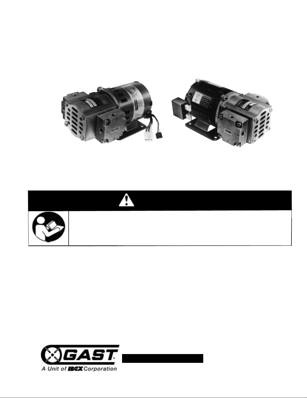
55R SERIES
ROCKING PISTON OIL-LESS PUMPS
OPERATION & MAINTENANCE MANUAL
Product Use Criteria:
• Pump only clean, dry air.
• Operate at 32ºF - 104ºF (0ºC - 40ºC).
• Protect unit from dirt & moisture.
• Do not pump flammable or explosive gases or
use in an atmosphere that contains such gases.
• Protect all surrounding items from exhaust air. This
exhaust air can become very hot.
• Corrosive gases and particulate material will
damage unit. Water vapor, oil-based contaminants
or other liquids must be filtered out.
• Consult your Gast Distributor/Representative
before using at high altitudes.
• This pump is oil-less and requires NO lubrication.
Thank you for purchasing this Gast product. It is manufactured to the highest standards
using quality materials. Please follow all recommended maintenance, operational
and safety instructions and you will receive years of trouble free service.
www.gastmfg.com
ISO 9001 & 14001 CERTIFIED
®Registered Trademark/™Trademark of Gast Manu facturing Inc., Copyright ©2002 Gast Manufacturing Inc. All Rights Reserved.
PART NO. 70 - 6600 G491PL (REV-F)
WARNING
PLEASE READ THIS MANUAL COMPLETELY BEFORE INSTALLING AND USING
THIS PRODUCT. SAVE THIS MANUAL FOR FUTURE REFERENCE AND
KEEP IN THE VICINITY OF THE PRODUCT.
Your safety and the safety of others
is extremely important.
We have provided many important safety messages
in this manual and on your product. Always read
and obey all safety messages.
This is the safety alert symbol. This symbol
alerts you to hazards that can kill or hurt you and
others. The safety alert symbol and the words
“DANGER” and “WARNING” will precede all safety
messages. These words mean:
You will
be killed or seriously injured if you don’t
follow instructions.
You can be killed or seriously injured if you don’t
follow instructions.
All safety messages will identify the hazard, tell you
how to reduce the chance of injury, and tell you
what can happen if the safety instructions are not
followed.
WARNING
DANGER
INSTALLATION
Correct installation is your responsibility. Make sure
you have the proper installation conditions and that
installation clearances do not block air flow.
Blocking air flow over the product in any way can
cause the product to overheat.
Mounting
Mounting the product to a stable, rigid operating surface
and using shock mounts will reduce noise and vibration.
Mounting the control module (DC unit only)
Controller can be damaged by static electricity, handle
appropriately.
Mount the speed control module in a protected location
near the pump. Do not block the flow of cooling air over
the module in any way. Plug the 3-wire and 5-wire
connectors on the pump into corresponding connectors
on the speed control module (see DC wiring diagram).
Accessories
Intake filters are required for dirty environments. 1/8” port
required (Gast Part No. B300Q). Check filters
periodically and replace when necessary. Consult your
Gast Distributor/Representative for additional filter
recommendations.
Plumbing
Remove plugs from the IN and OUT ports. Connect
with pipe and fittings that are the same size or larger
than the product’s threaded ports. Be sure to connect
the intake and exhaust plumbing to the correct inlet and
outlet ports. Ports will not support plumbing.
Install relief valves and gauges at inlet or outlet or both,
to monitor performance. Check valves may be required
to prevent back streaming through the pump.
Motor Control
It is your responsibility to contact a qualified
electrician and assure that the electrical installation
is adequate and in conformance with all national
and local codes and ordinances. The metal
capacitor must be grounded.
Determine the correct overload setting required to
protect the motor (see motor starter manufacturer’s
recommendations). Select fuses, motor protective
switches or thermal protective switches to provide
protection. Fuses act as short circuit protection for the
motor, not as protection against overload. Incoming line
fuses must be able to withstand the motor’s starting
current. Motor starters with thermal magnetic overload
or circuit breakers protect motor from overload or
reduced voltage conditions.
The wiring diagram supplied with the product provides
required electrical information. Check that power
source is correct to properly operate the dual-voltage
motors.
WARNING
c
Electrical Shock Hazard
Disconnect electrical power at the circuit breaker
or fuse box before installing this product.
Install this product where it will not come into
contact with water or other liquids.
Install this product where it will be weather
protected.
Electrically ground this product.
Failure to follow these instructions can result in
death, fire or electrical shock.
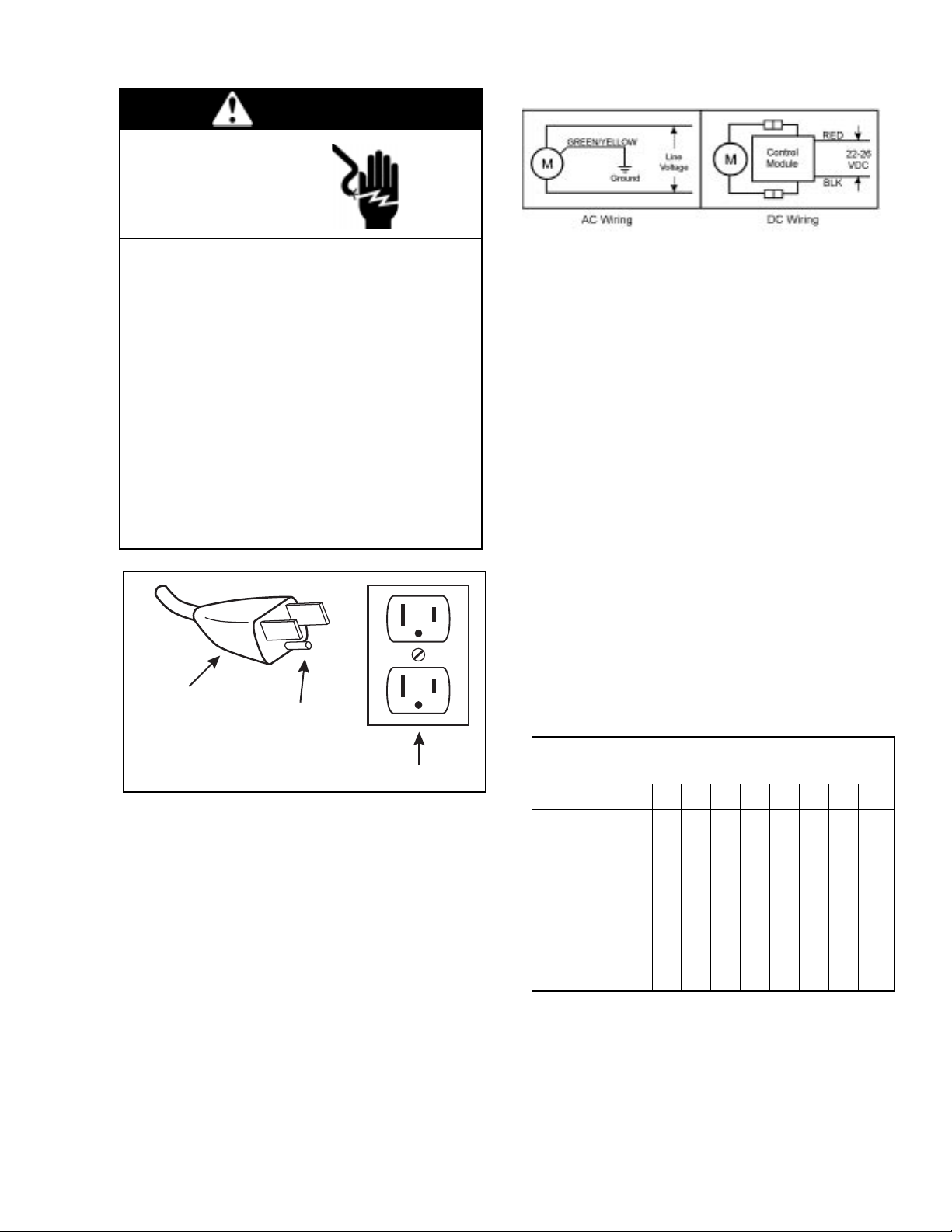
Electrical Connection
Model with a power supply cord:
This product must be grounded. For either 120-volt or
220/240-volt circuits connect power supply cord
grounding plug to a matching grounded outlet. Do not
use an adapter. (See above diagram.)
Check with a qualified electrician or serviceman if
the grounding instructions are not completely
understood, or if you are not sure whether the
product is properly grounded. Do not modify the
plug provided. If it will not fit the outlet, have the
proper outlet installed by a qualified electrician.
Model that is permanently wired:
This product must be connected to a grounded,
metallic, permanent wiring system, or an equipment
grounding terminal or lead on the product.
Power supply wiring must conform to all required safety
codes and be installed by a qualified person. Check
that supply voltage agrees with that listed on product
nameplate.
Extension cords:
Use only a 3-wire extension cord that has a 3-blade
grounding plug. Connect extension cord plug to a
matching 3-slot receptacle. Do not use an adapter.
Make sure your extension cord is in good condition.
Check that the gage wire of the extension cord is the
correct size wire to carry the current this product will
draw.
An undersized cord is a potential fire hazard, and will
cause a drop in line voltage resulting in loss of power
causing the product to overheat. The following table
indicates the correct size cord for length required and
the ampere rating listed on the product nameplate. If in
doubt, use the next heavier gage cord. The smaller
the gage number, the heavier the wire gage.
In the event of an electrical short circuit, grounding
reduces the risk of electric shock by providing an
escape wire for the electric current. This product may
be equipped with a power supply cord having a
grounding wire with an appropriate grounding plug.
The plug must be plugged into an outlet that is properly
installed and grounded in accordance with all local
codes and ordinances.
Minimum gage for extension cords
Amps Volts Length of cord in feet
120v 25 50 100 150 200 250 300 400 500
240v 50 100 200 300 400 500 600 800 1000
0-2 18 18 18 16 16 14 14 12 12
2-3 18 18 16 14 14 12 12 10 10
3-4 18 18 16 14 12 12 10 10 8
4-5 18 18 14 12 12 10 10 8 8
5-6 18 16 14 12 10 10 8 8 8
6-8 18 16 12 10 10 8 6 6 6
8-10 18 14 12 10 88664
10-12 16 14 10 886644
12-14 16 12 10 866642
14-16 16 12 10 866442
16-18 14 12 8 864422
18-20 14 12 8 664422
WARNING
c
Electrical Shock Hazard
This product must be properly grounded.
Do not modify the plug provided. If it will not
fit the outlet, have the proper outlet installed
by a qualified electrician.
If repair or replacement of the cord or plug is
necessary,do not connect the grounding wire
to either flat blade terminal. The wire with
insulation that is green or green with yellow
stripes is the grounding wire.
Check the condition of the power supply wiring.
Do not permanently connect this product to
wiring that is not in good condition or is
inadequate for the requirements of this product.
Failure to follow these instructions can result in
death, fire or electrical shock.
Grounded Plug
Grounding Pin
120-volt grounded connectors
shown. 220/240-volt grounded
connectors will differ in shape.
Grounded Outlet