

Page 1
www.gastmfg.com
ISO 9001 & 14001 CERTIFIED
ART NO. 70-350 G386PL (Rev. F)
WARNING
PLEASE READ THIS MANUAL COMPLETELY BEFORE INSTALLING AND USING
THIS MOTOR. SAVE THIS MANUAL FOR FUTURE REFERENCE AND
KEEP IN THE VICINITY OF THE MOTOR.
P
GAST LUBRICATED LABORATORY 23 SERIES ROTARY
VANE VACUUM PUMPS & COMPRESSORS
PERATION & MAINTENANCE MANUAL
O
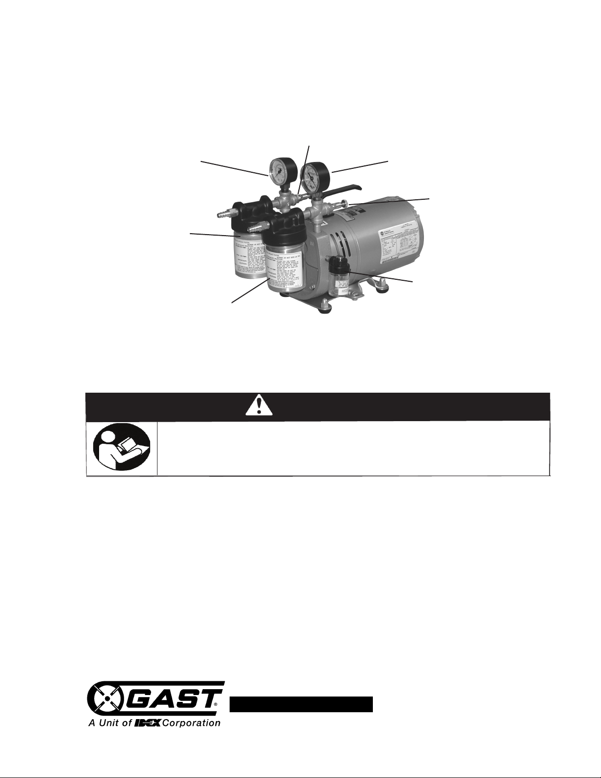
Relief Valve (hidden)
Pressure Gauge
The pressure gauge shows the
utput pressure..
o
Turn the regulator screw
clockwise to increase pressure.
Vacuum Gauge
he vacuum gauge shows the intake
T
pressure.
10 Micron Filter Element
Check muffler element each time oil
reservoir is filled; clean with soap and
water as needed, or replace. (See page 7
for Ordering Information).
10 Micron Filter Element
Check filter element each time oil
reservoir is filled; clean with soap and
water as needed, or replace. (See
page 7 for Ordering Information).
NOTE: Removes solid particles only.
Install a moisture trap if liquids could
be drawn into the pump.
Relief Valve
Turn the regulator screw clockwise to
increase vacuum. NOTE: Maximum
pressure and vacuum cannot be
produced at the same time.
Siphon Oiler
Models 0323, 0523: Check the oil level at
each use to ensure safe operation.
Constant Level Oiler (not shown)
Models 0823, 1023: Large oil reservoir;
check the oil level at longer intervals.
Product Use Criteria:
• Operate at 32ºF - 104ºF (0ºC - 40ºC).
• Protect unit from dirt & moisture.
• Protect all surrounding items from hot exhaust
air. This exhaust air can become very hot.
• Product is not a consumer product and is for
commercial applications only.
• Do not pump flammable or explosive gases or use
in an atmosphere that contains such gases.
• Corrosive gases and particulate material will
damage unit. Water vapor, oil-based contaminants
or other liquids must be filtered out.
• Consult your Gast Distributor/Representative
before using at high altitudes.
• Use Gast #AD220 or a detergent SAE#10
automotive engine oil for lubricating.
Page 2
c
Disconnect electrical power at the circuit breaker
or fuse box before installing this product.
Install this product where it will not come into
contact with water or other liquids.
Install this product where it will be weather
protected.
Electrically ground this product.
Failure to follow these instructions can result in
death, fire or electrical shock.
WARNING
Electrical Shock Hazard
WARNING
DANGER
Your safety and the safety of others
i
s extremely important.
We have provided many important safety messages
in this manual and on your product. Always read
and obey all safety messages.
This is the safety alert symbol. This symbol
alerts you to hazards that can kill or hurt you and
others. The safety alert symbol and the words
“DANGER” and “WARNING” will precede all safety
m
essages. These words mean:
Y
ou will
b
e killed or seriously injured if you don’t
follow instructions.
You can
be killed or seriously injured if you don’t
follow instructions.
All safety messages will identify the hazard, tell you
how to reduce the chance of injury, and tell you
what can happen if the safety instructions are not
followed.
Mounting
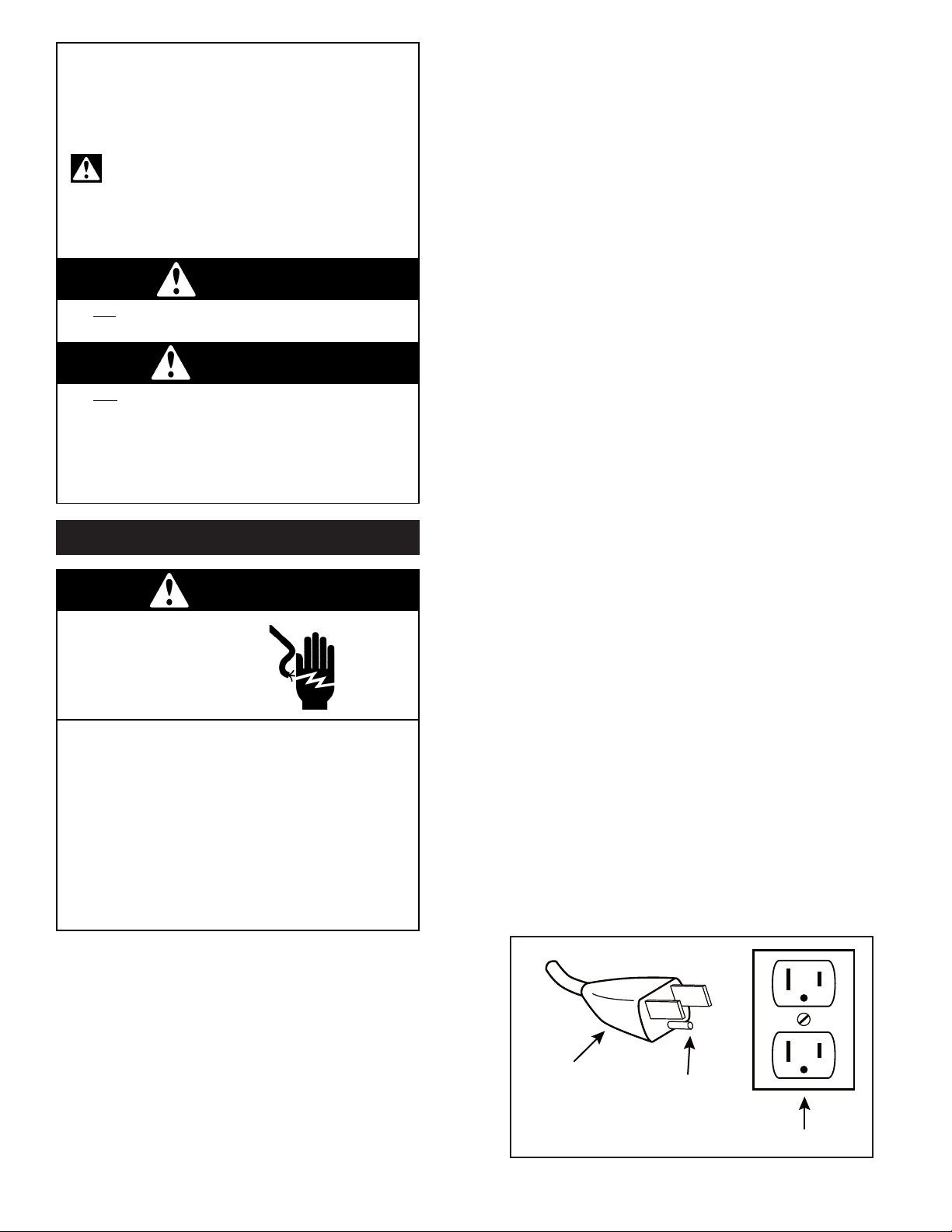
Grounded Plug
Grounding Pin
Grounded Outlet
120-volt grounded connectors
shown. 220/240-volt grounded
connectors will differ in shape.
DIAGRAM A
he pump and its solid base (preferably metal) should be
T
anchored to either a shelf, the floor, or another piece of
machinery. To save time and avoid inconvenience,
position the pump to provide easy access to all
ubricators, filters and mufflers.
l
Moisture Trap
Liquid or moisture vapor will damage the pump. Install a
oisture trap if liquids could be drawn into the pump. For
m
the correct type and size, contact your local Distributor or
the factory.
lumbing
P
To prevent air flow restriction, use pipe and fittings that
are the same size or larger than the threaded ports of the
pump. The ports are marked "IN" and "OUT". If the
istance is great, use lines with a larger diameter than
d
the connections. Give lines a uniform slope, place drain
cock at low point, and avoid extra elbows. For ease of
servicing, use a union or hose with clamps near the
pump (a hose helps eliminate noise and vibration). If a
vacuum/pressure supply tank is used, slope the line
towards tank, provide a drain at the bottom, and place a
check valve between the tank and pump so the pump will
not run backwards when turned off.
INSTALLATION
Correct installation is your responsibility. Make sure you
have the proper installation conditions and that
installation clearances do not block air flow. Proper
guards should be installed to prevent contact with
moveable parts of this pump. Do Not lift the unit by the
fan shroud.
Blocking air flow over the product in any way can cause
the product to overheat.
Mounting
Position the mounting the product to a stable, rigid
operating surface and using shock mounts will reduce
noise and vibration.
Motor Control
It is your responsibility to contact a qualified
electrician to assure that the electrical installation is
adequate and in conformance with all national and local
codes and ordinances.
Determine the correct overload setting required to
protect the motor (see motor starter manufacturerʼs
recommendations). Select fuses, motor protective
switches or thermal protective switches to provide
protection. Fuses act as short circuit protection for the
motor, not as protection against overload. Incoming line
fuses help to withstand the motorʼs starting current.
Motor starters with thermal magnetic overload or circuit
breakers protect motor from overload or reduced
voltage conditions.
The wiring diagram supplied with the product provides
required electrical information. Check that power
source is correct to properly operate the dual-voltage
motors.
Electrical Connection
2
Page 3

c
Disconnect electrical power supply cord before
performing maintenance on this product.
If product is hard wired into system, disconnect
electrical po
wer at the circuit breaker or fuse box
before performing maintenance on this product.
F
ailure to follow these instructions can result in
death, fire or electrical shock.
Electrical Shock Hazard
WARNING
WARNING
Injury Hazard
Air stream from product may contain solid or liquid
m
aterial that can result in eye or skin damage.
Wear hearing protection. Sound level from product
may exceed 85 db(A).
Failure to follow these instructions can result in eye
injury or other serious injury.
P
ump only clean dry air.
Do not pump flammable or explosive gases or use
i
n an atmosphere that contains such gases.
Install proper safety guards as needed. Pumps with
g
lass jars need safety guards to protect against
breaking glass.
Use only recommended air handling parts acceptable
for pressure not less than 70 psi.
Keep fingers and objects away from openings and
r
otating parts.
When provided, motor terminal covers must be in
place for safe operation.
Check that coupling guard and shroud are in place
before operating.
Product surfaces may become hot during operating,
allow product surfaces to cool before handling.
Do not direct air stream at body. Air stream from
product may contain solid or liquid material that can
result in eye or skin damage, wear proper eye
protection.
Do not spray flammable or combustible liquid.
Model with a power supply cord:
This product must be grounded. For either 120-volt or
220/240-volt circuits connect power supply cord
rounding plug to a matching grounded outlet. Do not
g
use an adapter. (See DIAGRAM A)
In the event of an electrical short circuit, grounding
reduces the risk of electric shock by providing an
scape wire for the electric current. This product may
e
be equipped with a power supply cord having a
grounding wire with an appropriate grounding plug.
The plug must be plugged into an outlet that is properly
nstalled and grounded in accordance with all local
i
codes and ordinances.
Check with a qualified electrician or serviceman if the
grounding instructions are not completely understood,
or if you are not sure whether the product is properly
grounded. Do not modify the plug provided. If it will not
fit the outlet, have the proper outlet installed by a
qualified electrician.
Model that is permanently wired:
This product must be connected to a grounded,
metallic, permanent wiring system, or an equipment
grounding terminal or lead on the product.
OPERATION
Power supply wiring must conform to all required safety
codes and be installed by a qualified person. Check
that supply voltage agrees with that listed on product
nameplate.
Extension cords:
Use only a 3-wire extension cord that has a 3-blade
grounding plug. Connect extension cord plug to a
matching 3-slot receptacle. Do not use an adapter.
Make sure your extension cord is in good condition.
Check that the gage wire of the extension cord is the
correct size wire to carry the current this product will
draw.
Minimum gage for extension cords
Amps Volts Length of cord in feet
120v 25 50 100 150 200 250 300 400 500
240v 50 100 200 300 400 500 600 800 1000
0-2 18 18 18 16 16 14 14 12 12
2-3 18 18 16 14 14 12 12 10 10
3-4 18 18 16 14 12 12 10 10 8
4-5 18 18 14 12 12 10 10 88
5-6 18 16 14 12 10 10 888
6-8 18 16 12 10 10 8666
8-10 18 14 12 10 88664
10-12 16 14 10 886644
12-14 16 12 10 866642
14-16 16 12 10 866442
16-18 14 12 8864422
18-20 14 12 8664422
3
It is your responsibility to operate this product at
recommended pressures or vacuum duties and room
ambient temperatures. Do Not start against a vacuum
or pressure load.
Start Up
If pump is extremely cold, let it warm up to room
temperature before starting. If motor fails to start or
slows down significantly under load, shut off and
disconnect from power supply. Check that the voltage
is correct for motor and that motor is turning in the
proper direction. Turning in the wrong direction will
drastically reduce vane life. Vane life will be drastically
reduced if motor is not operating properly. Vanes can
break or be damaged if motor/pump runs in the wrong
direction.
MAINTENANCE
Page 4
It is your responsibility to:
Air stream from product may contain solid or liquid
m
aterial that can result in eye or skin damage.
Flush this product in a well ventilated area.
Do Not use kerosene or other combustible solvents
to flush this product.
WARNING
Injury Hazard
W
ear eye protection when flushing this product.
Failure to follow these instructions can result in
eye injury or other serious injury.
• Regularly inspect and make necessary repairs to
product in order to maintain proper operation.
• Make sure that pressure and vacuum is released
from product before starting maintenance.
1. Disconnect electrical power supply.
2. Release all pressure and vacuum from pump.
3. Remove all accessories at the inlet and exhaust
ports.
4. Remove filter.
5. Start product. Place towel over exhaust port to
clean up solvent. If using liquid solvent, pour
several tablespoons directly into inlet port. If
using Gast Flushing Solvent, spray solvent for
5-10 seconds into inlet port.
6. Block the inlet port and draw a deep vacuum
for 15-20 seconds. Release the vacuum.
7. Listen for changes in the sound of the motor.
If motor sounds smooth, go to next step. If
motor does not sound like it is running
smoothly, repeat steps 5 and 6 until you can
hear a difference in the operating sound of the
pump.
8. Start the pump and let it run for 1 minute, then
turn pump off.
9. Replace all accessories at the inlet and exhaust
ports.
10. Replace filter before resuming operation.
WARNING
The pump surfaces may become very hot during
operation. do not touch these parts until the pump has
been turned off and allowed to cool.
Check intake and exhaust filters after first 500 hours of
operation. Clean filters and determine how frequently
filters should be checked during future operation. This
one procedure will help to assure the productʼs
performance and service life.
Clean filters when necessary by removing and washing
in a solvent or soap and water. After cleaning, dry with
compressed air to make sure all moisture is removed
before replacing filters.
Flushing
Flushing this product to remove excessive dirt, foreign
particles, moisture or oil that occurs in the operating
environment will help to maintain proper vane
performance. If your pump is not getting the vacuum or
pressure level expected, flushing is required. Vanes will
stick when dirty and may cause pump to be noisy or
inefficient.
Use only Gast Flushing Solvent or other non-petroleum
based flushing solvent. Do Not use kerosene or ANY
other combustible solvent to flush product.
Check that all external accessories such as relief valves
and gauges are attached to cover and are not damaged
before re-operating product.
SHUTDOWN PROCEDURES
It is your responsibility to follow proper shutdown
procedures to prevent product damage.
Failure to do so may result in premature pump failure.
The Gast Manufacturing lubricated Vacuum Pumps and
Compressors are constructed of ferrous metals or
aluminum which are subject to rust and corrosion when
pumping condensable vapors such as water. Follow the
steps below to assure correct storage and shutdown
between operating periods
1. Disconnect plumbing.
2. Allow the pump to run “open” for at least 5
minutes.
3. Fill oil reservoir to proper level.
4. Cover inlet port (vacuum side) and run pump
for 1-3 minutes. Shut the pup down under
vacuum.
5. Plug ports so dirt or other contaminants do not
enter unit. It is now ready for shut-down.
4
Page 5

SERVICE KIT INSTALLATION
c
Disconnect electrical power supply cord before
installing Service Kit.
If product is hard wired into system, disconnect
electrical power at the circuit breaker or fuse box
before installing Service Kit.
Disconnect air supply and vent all air lines to
release pressure or vacuum.
Failure to follow these instructions can result in
death, fire or electrical shock.
WARNING
Electrical Shock Hazard
Gast will NOT guarantee field-rebuilt product
performance. For performance guarantee, the product
must be returned to a Gast Authorized Service Facility.
Service Kit contents vary. Most contain vanes, gaskets
oiler wick and filter elements.
isposal
D
Parts of the rotary vane pumps and compressors,
shafts, iron or aluminum castings, plastic or glass
arts or bearings, may be recycled as scrap
p
materials.
Please note current regulations)
(
We have Gast Certified Service
Centers throughout the world. For
the most up-to-date listing, contact
one of our sales offices below:
World Headquarters
P.O. Box 97
2300 Highway M139
Benton Harbor, MI 49022
Ph: 269/926-6171
FAX: 269/925-8288
www.gastmfg.com
Gast Group Limited, United Kingdom
Unit 11, The I O Centre
Nash Road
Redditch, B98 7AS
United Kingdom
ph: +44 (0) 1527 504040
Fax: +44 (0) 1527 525262
www.gastmfg.com
Do Not attempt to remove the rotor. It is held in place
by Loctite and can only be serviced by a Gast
Authorized Service Facility.
PUMP DISASSEMBLY
1. Remove the 6 cap screws from the pump end
plate and remove the end plate.
DO NOT at any time remove the rotor or loosen
any of the electric motor thru-bolts.
2. Check for scoring on End Plate, Rotor, and
Body. Surfaces should be smooth. If severe
scoring is visible contact an Authorized Service
Facility.
3. Remove vanes.
4. Clean all surfaces with Gast recommended
Flushing solvent and dry well.
PUMP RE-ASSEMBLY
5. Apply a light coat of Gast recommended Oil
part# AD220 (an equivalent 10 wt. high
detergent oil can also be used) to the vanes.
6. Re-install vanes, noting the proper direction of
the beveled edge (Refer to exploded view).
7. Install End Plate with the six (6) cap screws.
Torque the screws to 100 lb.-in.
If the pump fails to produce proper vacuum or pressure,
or is excessively noisy, turn off and return unit to an
Authorized Service Facility.
5
Gast Hong Kong
Unit 12, 21/F, Block B
New Trade Plaza
6, On Ping Street, Shatin
N. T. Hong Kong
Ph: (852) 2690 1066
Fax: (852) 2690 1012
www.gasthk.com
Page 6

LUBRICATION
eries 0323 and 0523:
S
These models use a siphon oiler. The
lubrication rate is determined by the
temperature, the operating vacuum or
ressure, and the siphon jar oil level. Keep
p
the siphon jar filled to the line shown on the
jar. Either unscrew the jar or fill through the
spring-loaded cap.
All Models:
The oil wick should be folded in half, with the
two ends submerged in the oil at the bottom
of the Jar, and the folded center inserted into
the connector approximately 3/8" past the two
breather holes in the connector (but not
touching the feed hole leading to the pump).
Both the breather holes and the feed hole
must be unrestricted.
Series 0823 and 1023:
hese models use a constant level oiler. The
T
lubrication rate is determined by the temperature,
the vacuum or pressure at which the pump is
operating, and the siphon jar oil level
(determined by the vertical position of the tube in
the jar).
The lower end of the tube should be 1/4" from
the bottom of the oil jar for normal lubrication. To
reposition the tube, loosen the locknut and adjust
the sleeve up or down. Lock the new position
with the locknut. For faster lubrication, raise the
reservoir tube away from the bottom of the oil jar.
For slower lubrication, lower the reservoir tube
toward the bottom of the jar.
To replenish the oil, pull the reservoir upward out
of the adjusting sleeve and turn it over. Add oil
through the tube. When the upper reservoir is
filled, replace it through the adjusting sleeve and
firmly seat it against the top of the sleeve.
All Models:
The oil wick should be folded in half, with the two
ends submerged in the oil at the bottom of the
Jar, and the folded center inserted into the
connector approximately 3/8" past the two
breather holes in the connector (but not touching
the feed hole leading to the pump). Both the
breather holes and the feed hole must be
unrestricted.
6
Page 7
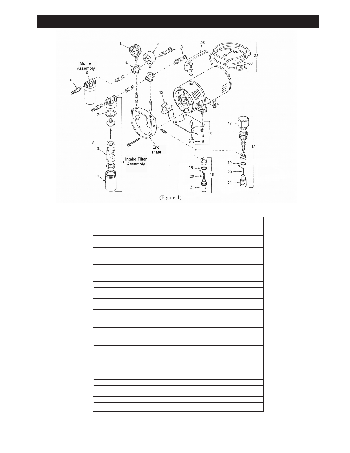
EXPLODE D PRODUCT VIEW, PARTS & ORDERI NG INFORMATION
0323/0523/0823/1023 SERIES
REF DESCRIPTION QTY 0323-V4 0823-V4B
NO. 0523-V4A 1023-V4
1 PRESSURE GAUGE 1 AA644B AA644B
2 VACUUM GAUGE 1 AA640 AA640
REGULATOR ASSEMBLY 2 AA986B AK502
3 PRESSURE RELIEF VALVE 1 -- AA600
VACUUM RELIEF VALVE 1 -- AA840
4 CROSS 2 BA601 BA602
5 MUFFLER ASSEMBLY 1 AB609B AB608A
6 HOSE NIPPLE 2 AA254D AA239
7
∆ COVER GASKET 2 AA404 AA404
INTAKE FILTER 1 AC433-1 AC433-1
8 ELEMENT ASSEMBLY
MUFFLER 1 AC434-1 AC434-1
9
∆ CARTRIDGE 2 AC393 AC393
10 METAL JAR 2 AA132 AA132
11 INTAKE FILTER ASSM. 1 AB609D AB608B
∆ VANE 4 AK731 AK741
12
13 FOOT SUPPORT ASSEMBLY 1 AC136 -14 FOOT SUPPORT 1 AC135 -15 RUBBER FOOT 4 -- AB319
16 SIPHON OILER 1 AA930B
17 OIL RESERVOIR 1 -- AD117
18 CONSTANT LEVEL OILER 1 -- AK125K
19 COVER GASKET - OILER 1 AA932 AA932
∆ WICK 1 AA934 AA934
20
21 JAR 1 AA935A AA935A
22 CORD/SWITCH/PLUG ASSM 1 AA896 AL239 (0823-V4B ONLY)
23 CORD/PLUG ASSEMBLY 1 -- AL142 (0823-V4B ONLY)
24 SWITCH 1 -- AC169 (0823-V4B ONLY)
25 HANDLE 1 AC174 AF555
*** SERVICE KIT 1 K556A K486
∆ PARTS IN REPAIR KIT
7
*** PART NOT SHOWN
Page 8
G
ast finished products, when properly installed and operated under normal conditions of use, are warranted by Gast to
be free from defects in material and workmanship for a period of twelve (12) months from the date of purchase from
Gast or an authorized Gast Representative or Distributor. In order to obtain performance under this warranty, the buyer
m
ust promptly (in no event later than thirty (30) days after discovery of the defect) give written notice of the defect to
Gast Manufacturing Incorporated, PO Box 97, Benton Harbor Michigan USA 49023-0097 or an authorized Service
C
enter (unless specifically agreed upon in writing signed by both parties or specified in writing as part of a Gast OEM
Quotation). Buyer is responsible for freight charges both to and from Gast in all cases.
This warranty does not apply to electric motors, electrical controls, and gasoline engines not supplied by Gast. Gast’s
w
arranties also do not extend to any goods or parts which have been subjected to misuse, lack of maintenance,
neglect, damage by accident or transit damage.
THIS EXPRESS WARRANTY EXCLUDES ALL OTHER WARRANTIES OR REPRESENTATIONS EXPRESSED OR
IMPLIED BY ANY LITERATURE, DATA, OR PERSON. GAST’S MAXIMUM LIABILITY UNDER THIS EXCLUSIVE
R
EMEDY SHALL NEVER EXCEED THE COST OF THE SUBJECT PRODUCT AND GAST RESERVES THE RIGHT,
AT ITS SOLE DISCRETION, TO REFUND THE PURCHASE PRICE IN LIEU OF REPAIR OR REPLACEMENT.
GAST WILL NOT BE RESPONSIBLE OR LIABLE FOR INDIRECT OR CONSEQUENTIAL DAMAGES OF ANY KIND,
h
owever arising, including but not limited to those for use of any products, loss of time, inconvenience, lost profit, labor
charges, or other incidental or consequential damages with respect to persons, business, or property, whether as a
result of breach of warranty, negligence or otherwise. Notwithstanding any other provision of this warranty, BUYER’S
REMEDY AGAINST GAST FOR GOODS SUPPLIED OR FOR NON-DELIVERED GOODS OR FAILURE TO FURNISH
GOODS, WHETHER OR NOT BASED ON NEGLIGENCE, STRICT LIABILITY OR BREACH OF EXPRESS OR
I
MPLIED WARRANTY IS LIMITED SOLELY, AT GAST’S OPTION, TO REPLACEMENT OF OR CURE OF SUCH
NONCONFORMING OR NON-DELIVERED GOODS OR RETURN OF THE PURCHASE PRICE FOR SUCH GOODS
A
ND IN NO EVENT SHALL EXCEED THE PRICE OR CHARGE FOR SUCH GOODS. GAST EXPRESSLY DISCLAIMS
ANY WARRANTY OF MERCHANTABILITY OR FITNESS FOR A PARTICULAR USE OR PURPOSE WITH RESPECT
T
O THE GOODS SOLD. THERE ARE NO WARRANTIES WHICH EXTEND BEYOND THE DESCRIPTIONS SET
FORTH IN THIS WARRANTY, notwithstanding any knowledge of Gast regarding the use or uses intended to be made
o
f goods, proposed changes or additions to goods, or any assistance or suggestions that may have been made by Gast
personnel.
Unauthorized extensions of warranties by the customer shall remain the customer’s responsibility.
C
USTOMER IS RESPONSIBLE FOR DETERMINING THE SUITABILITY OF GAST PRODUCTS FOR CUSTOMER’S
USE OR RESALE, OR FOR INCORPORA
T
ING
THEM INT
O OBJECTS OR APPLICA
T
IONS WHICH CUSTOMER
D
ESIGNS
, ASSEMBLES
, CONSTR
U
CTS OR MANUF
A
C
TURES
.
T
his warranty can be modified only by authorized Gast personnel by signing a specific, written description of any
modifications.
www.gastmfg.com
ISO 9001 & 14001 CERTIFIED
WARRANTY
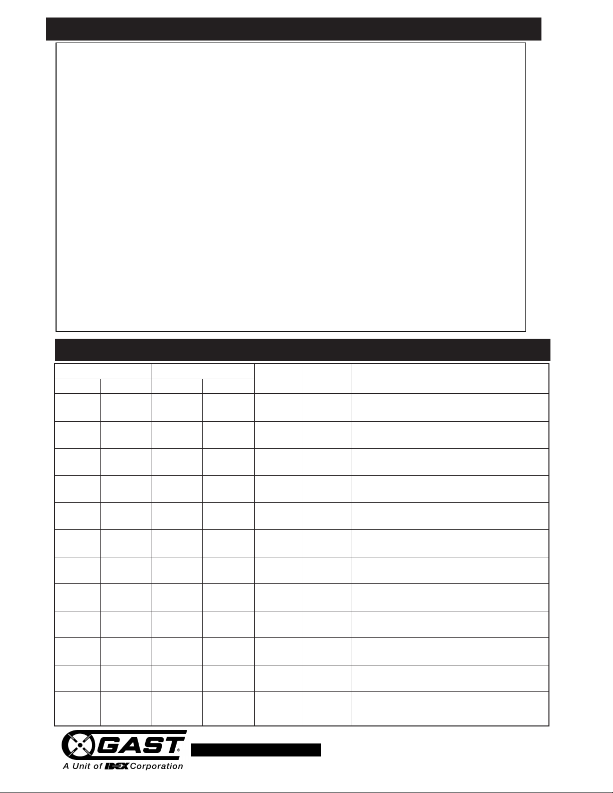
TROUBLES HOOTING CHART
Low High Pump Motor Reason and remedy
Vacuum Pressure Vacuum Pressure Overheat Overload for problem.
• • At pump ••Filter dirty.
• At pump ••Muffler dirty.
• At pump ••Vacuum line collapsed.
••••Relief valve set too high.
•• Relief valve set too low.
••At pump At pump • • Plugged vacuum/pressure line.
•• Vanes sticking.
•• Vanes worn.
•• Shaft seal worn.
•• ••Dust or offset powder in pump.
•• • Motor not wired correctly.
• • • • Running at too high an RPM.
Clean or replace.
Clean or replace.
Repair or replace.
Inspect and adjust.
Inspect and adjust.
Inspect and repair.
Clean or replace.
Replace.
Replace.
Inspect and clean.
Check wiring diagram and line voltage.
Check wiring diagram and line voltage.
- 269-926-6171
 Loading...