

Page 1
70-7050 G505PL (Rev. E)
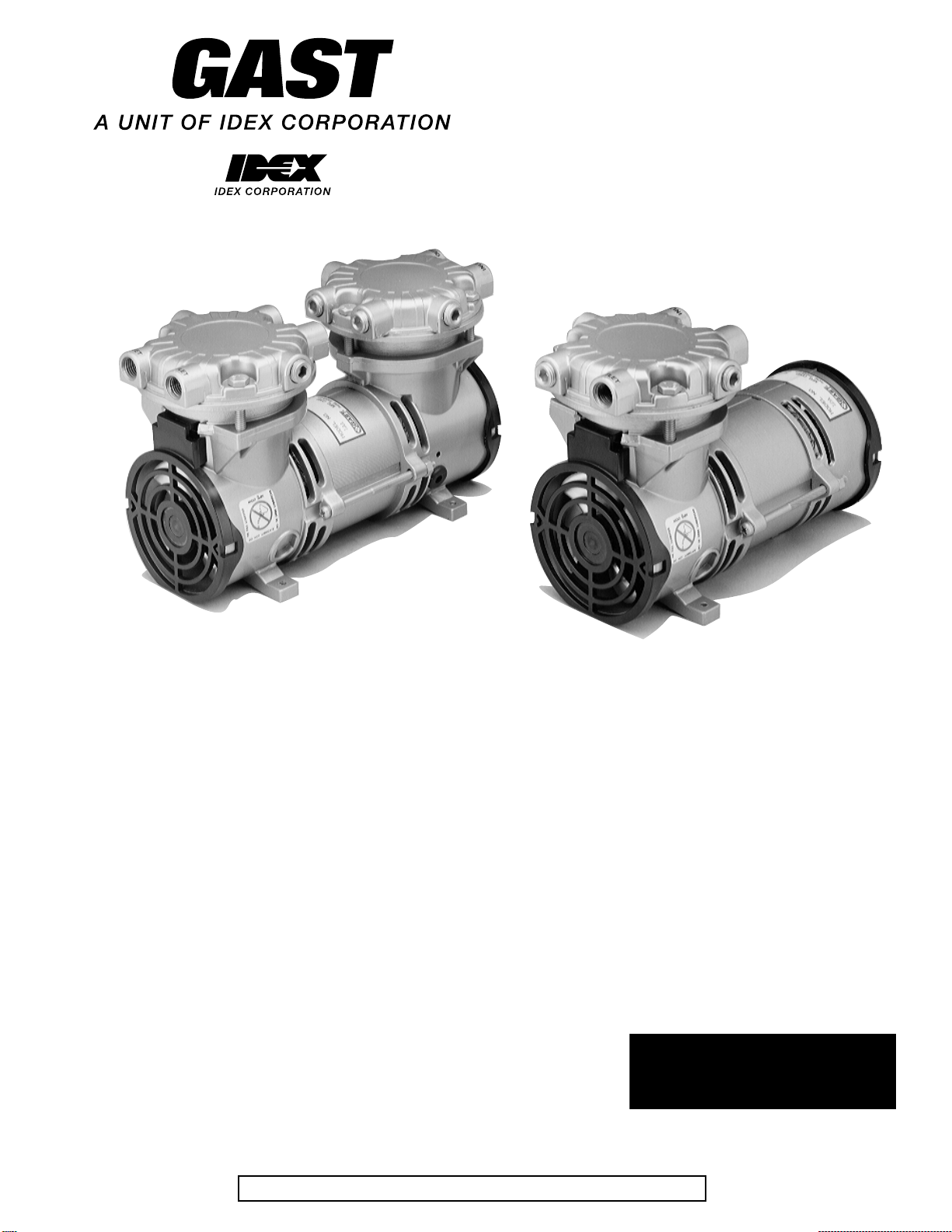
SOA/SAA/LOA/LAA OIL-LESS
VACUUM PUMPS &
COMPRESSORS
OPERATION &
MAINTENANCE MANUAL
CONTENTS:
General Information and Installation....................................................................................................... 2
Operation ................................................................................................................................................. 3
Maintenance and Shut-Down Procedures................................................................................................ 4
SAA/LAA Exploded View and Parts Ordering Information ................................................................... 5
SOA/LOA Exploded View and Parts Ordering Information ................................................................... 6
Service Kit Installation and Troubleshooting Guide ............................................................................... 7
Warranty and Authorized Service Facilities ............................................................................................ 8
Visit us at our website
www.gastmfg.com
KEEP THIS DOCUMENT FOR FUTURE REFERENCE
Page 2

This is the hazard alert symbol: m. When you see this
symbol, be aware that personal injury or property
damage is possible. The hazard is explained in the text
following the symbol. Read the information carefully
before proceeding.
The following is an explanation of the three
different types of hazards:
m DANGER Severe personal injury or death will
occur if hazard is ignored.
m WARNING Severe personal injury or death can
occur if hazard is ignored.
m CAUTION Minor injury or property damage
can occur if hazard is ignored.
If exposed to the elements unit must be weather-protected.
m WARNING Beware of any exposed and/or movable
parts. Proper guards should be in place to
prevent personal and/or property damage.
m CAUTION Do not block flow of cooling air ov er unit in
any wa y. This will cause unit to o verheat.
Mounting
Unit may be installed in any orientation as long as flow
of cool, ambient air over unit is not blocked. To reduce
noise and vibration, use shock mounts and affix unit to a
stable, rigid operating surface.
m CAUTION Remove plastic plugs in ports before
starting unit to avoid flying projectile and/
or lack of performance.
GENERAL INFORMATION
This unit is designed for moving air only and under no
circumstances is to be used with any other gases, fluids,
particles, solids, or any substance mixed with air.
m DANGER Pumping flammable or explosive gases or
operating this unit in an atmosphere
containing them can result in fire or
explosion damage to unit and surrounding
environment.
m CAUTION Do not allow corrosive gases or particulate
material to enter unit. Water vapor, oilbased contaminants, or other liquids must
be filtered out. Foreign materials will
damage unit by gumming up parts and
causing unit to fail.
m CAUTION This unit’s e xhaust air can become v ery hot.
Hot exhaust air can damage temperaturesensitive equipment and will burn skin if
exposed to air stream.
Ambient temperature should not exceed 40˚C (104˚F).
For operation at high temperatures, consult the factory.
Performance is reduced by low atmospheric pressure
found at high altitudes. Consult a Gast distributor for
details.
Never lubricate this oil-less piston unit. Most
components are made of aluminum and valves are
stainless steel.
INSTALLATION
m WARNING To avoid risk of electrocution do not use
this product in an area where it could
come in contact with water or other liquids.
Wiring
m WARNING Incorrect wiring can result in electric shock
and cause permanent damage to unit.
Wiring must conform to all required safety codes and be
installed by a qualified person. Grounding is required.
All power to motor must be de-energized and
disconnected when servicing.
Grounding Instructions
These instructions apply to 120-volt units and where
indicated to units wired for 220-240 volts. See motor
nameplate on unit for voltage requirements.
For all grounded, cord-connected products:
This product should be grounded. In the event of an electrical
short circuit, grounding reduces the risk of electric shock by
providing an escape wire for the electric current this product is
equipped with a cord having a grounding wire with an
appropriate grounding plug. The plug must be plugged into
an outlet that is properly installed and grounded in
accordance with all local codes and ordinances.
m DANGER
Improper installation of the grounding plug
can result in a risk of electric shock. If
repair or replacement of the cord or plug is
necessary, do not connect the grounding
wire to either flat blade terminal. The wire
with insulation having an outer surface that
is green with or without yellow stripes is
the grounding wire.
Check with a qualified electrician or serviceman if the
grounding instructions are not completely understood, or if in
doubt as to whether the product is properly grounded. Do not
modify the plug provided; if it will not fit the outlet, have the
proper outlet installed by a qualified electrician.
2
Page 3
For a grounded, cord-connected product rated less than 15
amperes and intended for use on a nominal 120 volt
supply circuit:
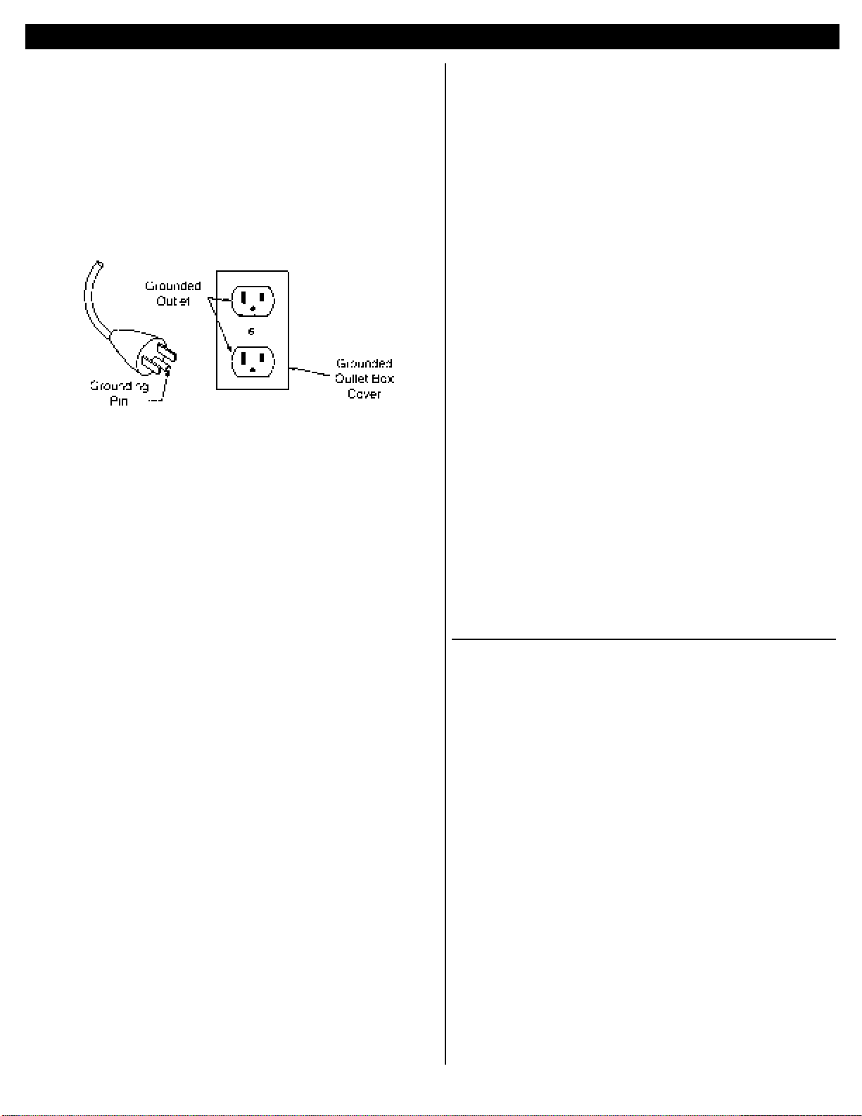
This product is for use on a nominal 120-volt circuit and has
a grounding plug that looks like the plug illustrated in Figure
1. Make sure that the product is connected to an outlet having
the same configuration as the plug. No adapter should be used
with this product
Figure 1
For all other grounded, cord-connected products:
This product is for use on a circuit having a nominal rating
more than I20 volts (or 220-240 volts) …and is
factory-equipped with a specific electric cord and plug to
permit connection to a proper electric circuit. Make sure that
the product is connected to an outlet having the same
configuration as the plug. No adapter should be used with this
product if the product must be reconnected for use on a
different type of electric circuit, the reconnection should be
made by qualified service personnel.
For a permanently connected product:
This product should be connected to a grounded, metallic,
permanent wiring system, or an equipment-grounding
terminal or lead on the product
Extension Cords:
Use only a 3-wire extension cord that has a 3-blade grounding
plug, and a 3-slot receptacle that will accept the plug on the
product Make sure your extension cord is in good condition.
When using an extension cord, be sure to use one heavy,
enough to carry the current your product will draw. For
lengths less than 25 feet, No.18 AWG extension cords should
be used. An undersized cord will cause a drop in line voltage
resulting in loss of power and overheating.
Exception: A 2-conductor or 3-conductor extension cord may
be used for a double-insulated or 2-wire product.
Refer to wiring tag supplied with unit, for diagram
and capacitor option. For any DC unit - red lead goes
to positive side of power source.
Plumbing
To prevent air flow restriction, use pipe and fittings
that are same size or larger than unit’s threaded ports.
NOTE: Be sure to connect intake and exhaust plumbing
to correct inlet and outlet ports.
Accessories
Filters and mufflers are supplied on some models. Check
periodically and replace when necessary. Consult a Gast
Representative for f ilter recommendations. F or best
results, install relief valves and g auges at inlet or outlet, or
both, to monitor performance.
Electric Motor Control
Motor must be protected against short circuit, overload
and excessive temperature rise. Fuses, motor-protective
switches and thermal-protective switches provide
necessary protection in these circumstances. Fuses only
serve as a short circuit protection of motor (wiring
fault). Fuses in the incoming line should be chosen so as
to be able to withstand the starting current of the motor,
not as a protection against overload.
Motor starters, incorporating thermal-magnetic overload
or circuit breakers protect motor from overload or
reduced voltage conditions.
Selection of correct overload setting is required to
provide best possible protection. Refer to motor starter
manufacturer’s recommendations.
OPERATION
m WARNING Solid or liquid material exiting unit can
cause eye or skin damage. Keep away
from air stream.
m WARNING Disconnect power before servicing to
avoid electric shock or accidental startup. The motor may be thermally protected and will restart automatically when
it cools if the thermal protection switch is
tripped.
m WARNING Do not operate without grille(s), if pro-
vided, in place. Failure to do so could
result in severe personal injury.
m WARNING Head surface(s) can be very hot depend-
ing on unit duty and speed. Do not touch
these parts during operation.
m CAUTION Do not operate units above recom-
mended pressures or vacuum duties.
This will overheat unit.
3
Page 4

Starting
If unit is extremely cold let it warm up to room
temperature before starting. If unit does not operate
properly, see troubleshooting guide on page 7. Do not
start against a vacuum or pressure load.
NOTE: Some of these models may exceed 70 dB(A).
When in close proximity to these models
hearing protection is required. Refer to
Technical Data Sheet for specific model.
MAINTENANCE
Filter Inspection and Replacement
Intake filter and mufflers require periodic inspection and
replacement. Initial inspection is suggested at 500
hours, then user should determine frequency thereafter.
Most problems can be prevented by keeping filters and
mufflers clean. Dirty filters and mufflers decrease unit
performance and can decrease unit life.
m WARNING Do not touch unit cylinders and heads as
they becomes very hot during operation
and will burn skin on contact. Wait until
unit has been turned off and allowed to
cool before touching it.
m WARNING Disconnect power before servicing to
avoid electric shock.
Some filter element(s) are held together by a snap fit.
Refer to exploded view during the following procedure.
1. Turn off unit.
2. Isolate from power source.
3. Release all pressure and vacuum from unit.
4. Remove filter cover.
5. Inspect filter felt.
6. Replace felt if it is completely covered with
contamination or has indicated an increase in
differential pressure.
7. Assemble felt and filter cover.
8. Check for any damage to external accessories such as
relief valves and gauges, before putting unit back into
service.
SHUTDOWN PROCEDURES
Proper shutdown procedures must be followed to pre v ent
unit damage. Failure to do so may result in premature unit
failure. Gast Manufacturing oil-less units are constructed of
ferrous metals or aluminum which are subject to rust and
corrosion when pumping condensable vapors such as water.
Follow steps belo w to assure correct storage and shutdo wn
between use:
1. NEVER oil this oil-less unit.
2. After using this unit, disconnect plumbing and allow unit
to run “open” for at least 5 minutes before shutdown.
3. Plug open ports to prevent dirt or other contaminants
from entering unit.
It is now ready for shutdown or storage.
4
Page 5
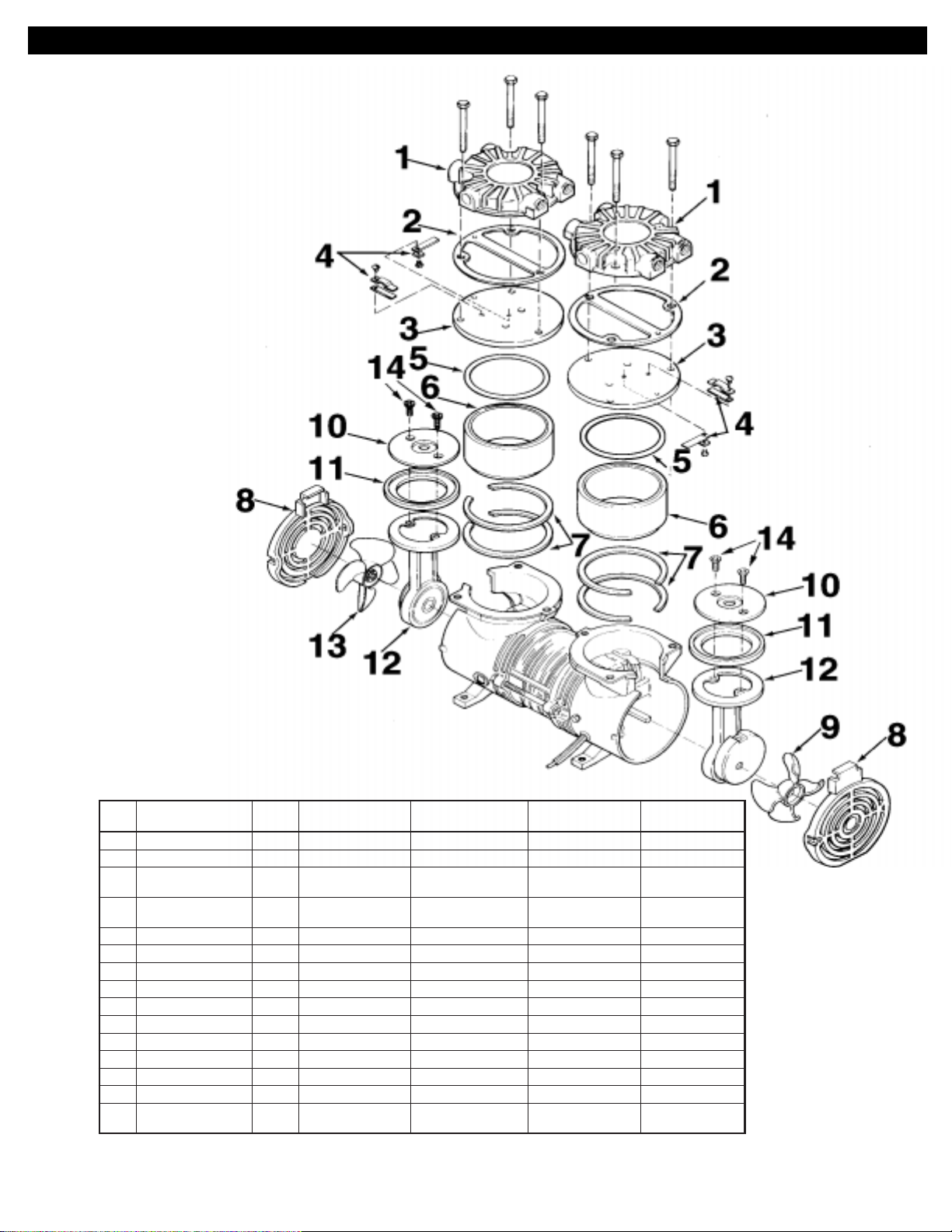
SAA/LAA EXPLODED VIEW & PARTS ORDERING INFORMATION
SAA-P107-NQ
feR
oNoNoNoNoN
noitpircseDytQQN-901V-AASQN-701P-AASQN-101-AALQN-211P-AAL
1daeH2743JA743JA743JA743JA
•
2teksaGdaeH2A404JAA404JAA404JAA404JA
•
3ylbmessAetalPevlaV
4sevlaV
*
(
)dedulcnisevlav
*
2A343JA343JA)1(
A343JA)1(
4718FA718FA379GA)2(
397JA)1(
493KA)1(
728JA)2(
•
5gnir-O2971HA971HA971HA971HA
6rednilyC2243JA243JAB573JAB573JA
7smihS
.qersa
543JA543JA543JA543JA
8ellirG2B477GAB477GAB477GAB477GA
9naF1658JA658JA658JA658JA
01etalPreniateR2B771HAB771HA773KA773KA
•
11puC2571HA571HA628JA628JA
21doRgnitcennoC2A833JAF803JAD083KAD083KA
31naF1B587FAB587FAB587FAB587FA
•
41swercSetalPreniateR4755BB755BB755BB755BB
tiKecivreS2757K)2(657K)1(
757K)1(
•
.srebmunlairesdnaledometelpmocevigesaelp,strapgniredrorognidnopserrocnehW
767K)1(
377K)1(
.yrotcafehttlusnocsledomMEOcificepsroF.sledomkcotsroferadetsilstraP.tiKecivreSnidedulcnistrapsetoneD
5
397JA)1(
493KA)1(
379GA)2(
728JA)2(
767K)1(
377K)1(
Page 6
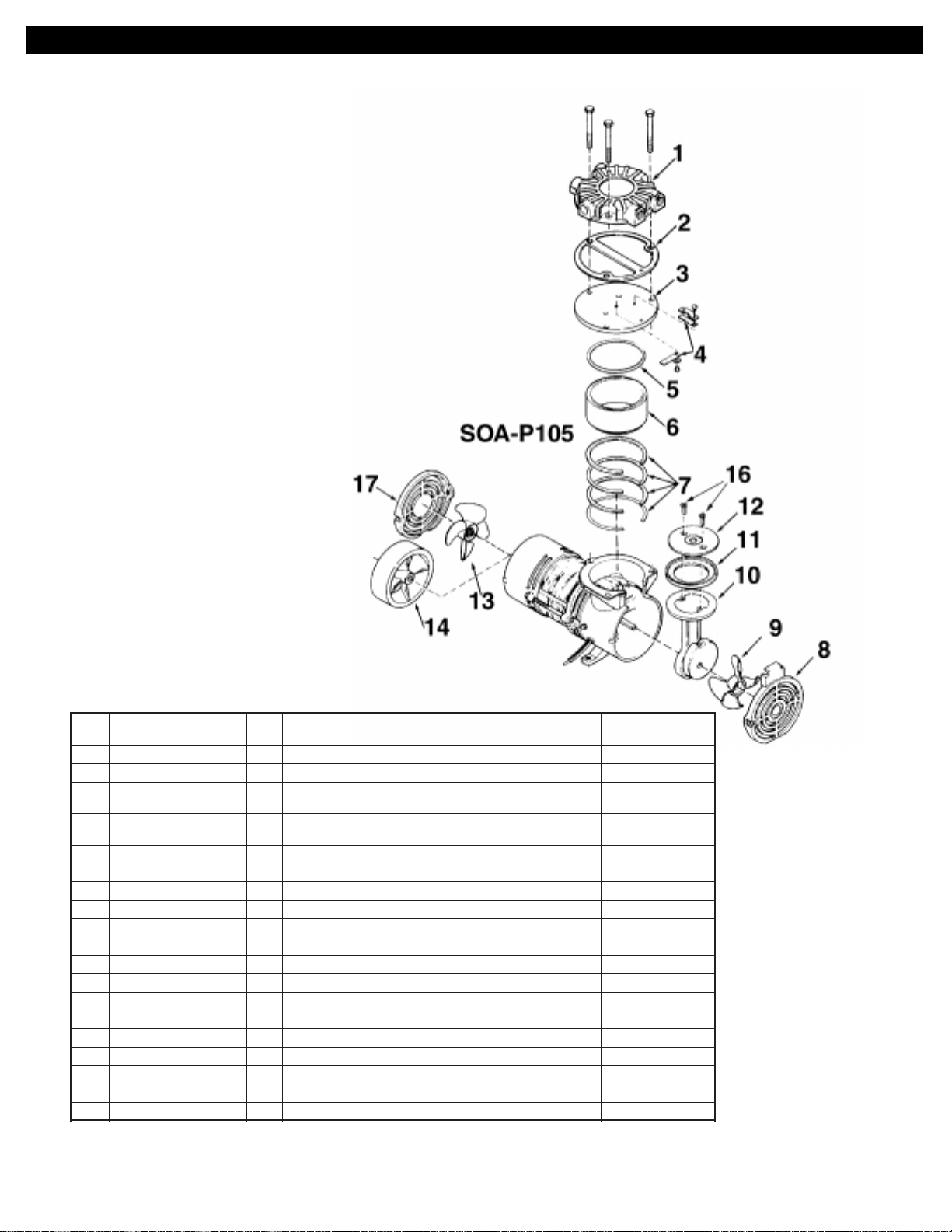
SOA/LOA EXPLODED VIEW & PARTS ORDERING INFORMATION
feR
oNoNoNoNoN
noitpircseDytQAM-501P-AOSAN-501V-AOSBH-101-AOLQN-201P-AOL
1daeH1743JA743JA743JA743JA
•
2teksaGdaeH1A404JAA404JAA404JAA404JA
•
3ylbmessAetalPevlaV
4sevlaV
*
(
*
)dedulcnisevlav
1
H343JAA343JA397JA397JA
2396HA718FA379GA)1(
728JA)1(
•
5gnir-O1971HA971HA787JA787JA
6rednilyC1243JA243JAB573JAB573JA
7smihS
.qersa
543JA543JA543JA543JA
8ellirGtnorF1B477GAB477GAB477GAB477GA
9naF1658JA658JA658JA658JA
01ylbmessAdoRgnitcennoC1D803JAA833JAB083KA083KA
•
11puC1571HA571HA628JA628JA
21etalPreniateR1B771HAB771HA773KA773KA
31naF1B587FAB587FAB587FA
41naFaitrenI1 776JA
51gniRecnareloT1 409JA
•
61swercSetalPreniateR2755BB755BB755BB755BB
71ellirG1447GA447GA447GA
)detartsullItoN(niPlewoD1 784KA
tiKecivreS1067K757K767K767K
•
.srebmunlairesdnaledometelpmocevigesaelp,strapgniredrorognidnopserrocnehW
.yrotcafehttlusnocsledomMEOcificepsroF.sledomkcotsroferadetsilstraP.tiKecivreSnidedulcnistrapsetoneD
379GA)1(
728JA)1(
6
Page 7
TROUBLESHOOTING GUIDE
SERVICE KIT INSTALLATION
NOTE: Gast will not guarantee performance of a fieldrebuilt unit. Return unit to a Gast Authorized Service
facility, or perform rebuild procedures described below.
Kits contain most or all of the following: Head Gasket, Valve
Plate Assembly, Retainer Plate Screws, O-ring, and Cup.
Kits are used for several models and may contain extra
parts not applicable for your specific model. Refer to
exploded view.
Disassembly:
1. Disconnect unit from power source.
m WARNING Disconnect power before servicing to
avoid electric shock.
2. Vent all air lines to unit to remove pressure.
m WARNING V ent all air lines to unit to remo v e pressure
before servicing it. Failure to do so can
result in severe personal injury.
3. Remove head bolts.
4. Remove gasket, head, and valve plate assembly
(Note orientation of head assembly for re-assembly).
5. Carefully remove cylinder and shims (Be sure to
replace all shims, as the y are matched to cylinder and
rod assembly height dimensions). Remo v e two retainer
plate screws on retainer plate (may require heat to
break adhesive on retainer screws) and discard old cup.
6. Clean residue from cylinder walls with soft cloth
using non-petroleum, non-oil-based solvent. DO NOT
use kerosene, gasoline, or any flammable substance.
Re-assembly:
7. Replace cylinder and shims.
8. Place retainer plate in new cup and push both down
into cylinder.
9. Install new retainer plate screws and torque to 35 in-lbs.
10. Install O-ring into groove of cylinder
11. Install valv e plate, head gasket (note gask et orientation),
and head, on cylinder so ports are in original orientation.
12. Install and snug all head bolts and torque to 80 in-lbs.
NOTE: Before putting unit into service, ensure that any
external accessories such as relief valves and
gauges attached to head have not been damaged.
EDIUGGNITOOHSELBUORT
nosaeRelbissoP
retliFytriDX X
relffuMytriDXXX
sevlaVytriDXX
sevlaVdegamaDXXXX
puCnroW/degamaDXX
gnimmihSrednilyCreporpmIXXXXXX
esoHykaeLXX
evlaVkcehCykaeL X
eniLerusserPromuucaVdeggulPXXXXX
egatloVwoLXXXX
evlaVfeileRykaeLXX
woLhgiH
erusserP
woL
muucaVmuucaV
muucaVmuucaV
muucaV
evissecxE
esioNesioN
esioNesioN
esioN
gnitaehrevO
t'noW
tratStratS
tratStratS
tratS
7
Page 8

YOUR WARRANTY
Gast finished products, when properly installed and operated under normal conditions of use, are warranted by Gast to
be free from defects in material and workmanship for a period of twelve (12) months from the date of purchase from
Gast or an authorized Gast Representative or Distributor. In order to obtain performance under this warranty, the buyer
must promptly (in no event later than thirty (30) days after discovery of the defect) give written notice of the defect to
Gast Manufacturing Incorporated, PO Box 97, Benton Harbor Michigan USA 49023-0097 or an authorized Service
Center (unless specifically agreed upon in writing signed by both parties or specified in writing as part of a Gast OEM
Quotation). Buyer is responsible for freight charges both to and from Gast in all cases.
This warranty does not apply to electric motors, electrical controls, and gasoline engines not supplied by Gast. Gast’s
warranties also do not extend to any goods or parts which have been subjected to misuse, lack of maintenance, neglect, damage by accident or transit damage.
THIS EXPRESS WARRANTY EXCLUDES ALL OTHER WARRANTIES OR REPRESENTATIONS EXPRESSED
OR IMPLIED BY ANY LITERATURE, DATA, OR PERSON. GAST’S MAXIMUM LIABILITY UNDER THIS
EXCLUSIVE REMEDY SHALL NEVER EXCEED THE COST OF THE SUBJECT PRODUCT AND GAST
RESERVES THE RIGHT, AT ITS SOLE DISCRETION, TO REFUND THE PURCHASE PRICE IN LIEU OF
REPAIR OR REPLACEMENT.
GAST WILL NOT BE RESPONSIBLE OR LIABLE FOR INDIRECT OR CONSEQUENTIAL DAMAGES OF
ANY KIND, however arising, including but not limited to those for use of any products, loss of time, inconvenience,
lost profit, labor charges, or other incidental or consequential damages with respect to persons, business, or property,
whether as a result of breach of warranty, negligence or otherwise. Notwithstanding any other provision of this
warranty, BUYER’S REMEDY AGAINST GAST FOR GOODS SUPPLIED OR FOR NON-DELIVERED GOODS
OR FAILURE TO FURNISH GOODS, WHETHER OR NOT BASED ON NEGLIGENCE, STRICT LIABILITY OR
BREACH OF EXPRESS OR IMPLIED WARRANTY IS LIMITED SOLELY, AT GAST’S OPTION, TO
REPLACEMENT OF OR CURE OF SUCH NONCONFORMING OR NON-DELIVERED GOODS OR RETURN
OF THE PURCHASE PRICE FOR SUCH GOODS AND IN NO EVENT SHALL EXCEED THE PRICE OR
CHARGE FOR SUCH GOODS. GAST EXPRESSLY DISCLAIMS ANY WARRANTY OF MERCHANTABILITY
OR FITNESS FOR A PARTICULAR USE OR PURPOSE WITH RESPECT TO THE GOODS SOLD. THERE ARE
NO WARRANTIES WHICH EXTEND BEYOND THE DESCRIPTIONS SET FORTH IN THIS WARRANTY,
notwithstanding any knowledge of Gast regarding the use or uses intended to be made of goods, proposed changes or
additions to goods, or any assistance or suggestions that may have been made by Gast personnel.
Unauthorized extensions of warranties by the customer shall remain the customer’s responsibility.
CUSTOMER IS RESPONSIBLE FOR DETERMINING THE SUITABILITY OF GAST PRODUCTS FOR
CUSTOMER’S USE OR RESALE, OR FOR INCORPORATING THEM INTO OBJECTS OR APPLICATIONS
WHICH CUSTOMER DESIGNS, ASSEMBLES, CONSTRUCTS OR MANUFACTURES.
This warranty can be modified only by authorized Gast personnel by signing a specific, written description of any
modifications.
8
 Loading...