

Page 1
www.gastmfg.com
ISO 9001 & 14001 CERTIFIED
®Registered Trademark/™Trademark of Gast Manu facturing Inc., Copyright © 2002 Gast Manufacturing Inc. All Rights Reserved.
PART NO. 70 - 6900 G497PL (REV-H)
WARNING
PLEASE READ THIS MANUAL COMPLETELY BEFORE INSTALLING AND USING
THIS PRODUCT. SAVE THIS MANUAL FOR FUTURE REFERENCE AND
KEEP IN THE VICINITY OF THE PRODUCT.
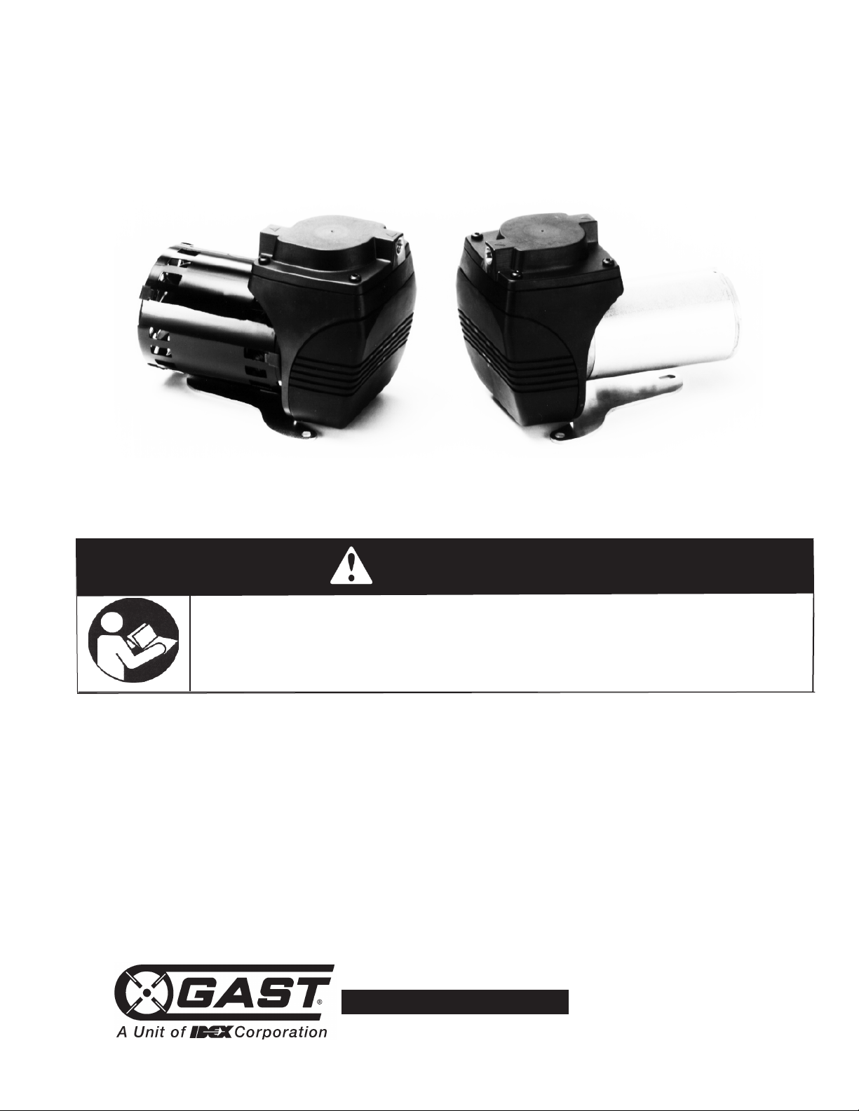
22D SERIES
DIAPHRAGM OIL-LESS PUMPS
OPERATION & MAINTENANCE MANUAL
Thank you for purchasing this Gast product. It is manufactured to the highest standards
using quality materials. Please follow all recommended maintenance, operational
and safety instructions and you will receive years of trouble free service.
Product Use Criteria:
• Pump only clean, dry air.
• Operate at 32ºF - 104ºF (0ºC - 40ºC).
• Protect unit from dirt & moisture.
• Do not pump flammable or explosive gases or
use in an atmosphere that contains such gases.
• Protect all surrounding items from exhaust air. This
exhaust air can become very hot.
• Corrosive gases and particulate material will
damage unit. Water vapor, oil-based contaminants
or other liquids must be filtered out.
• Consult your Gast Distributor/Representative
before using at high altitudes.
• This pump is oil-less and requires NO lubrication.
Page 2
Your safety and the safety of others
c
Disconnect electrical power at the circuit breaker
or fuse box before installing this product.
Install this product where it will not come into
contact with water or other liquids.
Install this product where it will be weather
protected.
Electrically ground this product.
Failure to follow these instructions can result in
death, fire or electrical shock.
WARNING
Electrical Shock Hazard
is extremely important.
We have provided many important safety messages in
this manual and on your product. Always read and
bey all safety messages.
o
Correct installation is your responsibility. Make sure you
have the proper installation conditions and that
installation clearances do not block air flow.
Blocking air flow over the product in any way can cause
the product to overheat.
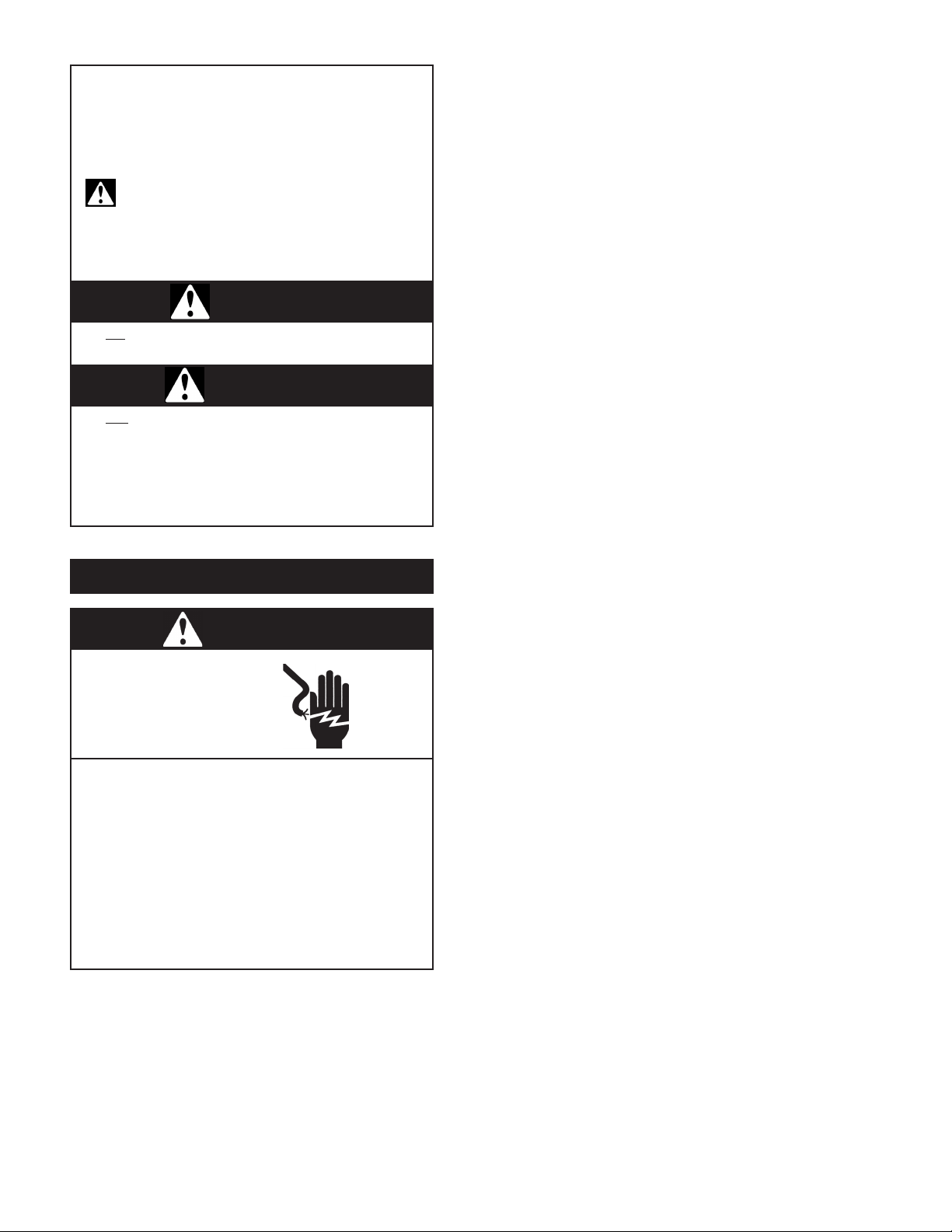
This is the safety alert symbol. This symbol
alerts you to hazards that can kill or hurt you and
thers. The safety alert symbol and the words
o
“DANGER” and “WARNING” will precede all safety
messages. These words mean:
DANGER
You will
instructions.
be killed or seriously injured if you donʼt follow
WARNING
You can
instructions.
All safety messages will identify the hazard, tell you
how to reduce the chance of injury, and tell you what
can happen if the safety instructions are not followed.
INSTALLATION
be killed or seriously injured if you donʼt follow
Mounting
Mounting the product to a stable, rigid operating surface
and using shock mounts will reduce noise and vibration.
Plumbing
Remove plugs from the IN and OUT ports. Connect
ith pipe and fittings that are the same size or larger
w
than the productʼs threaded ports. Be sure to connect
the intake and exhaust plumbing to the correct inlet and
outlet ports. Ports will not support plumbing.
Accessories
Install gauges in the lines to monitor performance. A
relief valve can be installed at the inlet or outlet, or both.
Consult a Gast representative for performance limitations.
If operated in a dirt-contaminated atmosphere, a suitable
filter should be used to ensure long service. For
recommendations, contact a Gast representative.
Motor Control
It is your responsibility to contact a qualified
electrician and assure that the electrical installation is
adequate and in conformance with all national and local
codes and ordinances. The metal capacitor must be
grounded.
Determine the correct overload setting required to
protect the motor (see motor starter manufacturerʼs
recommendations). Select fuses, motor protective
switches or thermal protective switches to provide
protection. Fuses act as short circuit protection for the
motor, not as protection against overload. Incoming line
fuses must be able to withstand the motorʼs starting
current. Motor starters with thermal magnetic overload
or circuit breakers protect motor from overload or
reduced voltage conditions.
The wiring diagram supplied with the product provides
required electrical information. Check that power
source is correct to properly operate the dual-voltage
motors.
Page 3
Electrical Connection
c
This product must be properly grounded.
Do not modify the plug provided. If it will not
fit the outlet, have the proper outlet installed
by a qualified electrician.
If repair or replacement of the cord or plug is
necessary, do not connect the grounding wire
to either flat blade terminal. The wire with
insulation that is green or green with yellow
stripes is the grounding wire.
Check the condition of the power supply wiring.
Do not permanently connect this product to
wiring that is not in good condition or is
inadequate for the requirements of this product.
Failure to follow these instructions can result in
death, fire or electrical shock.
WARNING
Electrical Shock Hazard
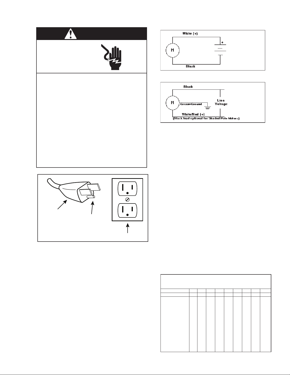
Grounded Plug
Grounding Pin
Grounded Outlet
120-volt grounded connectors
shown. 220/240-volt grounded
connectors will differ in shape.
DC Wiring
AC Wiring
In the event of an electrical short circuit, grounding
reduces the risk of electric shock by providing an
escape wire for the electric current. This product may
be equipped with a power supply cord having a
grounding wire with an appropriate grounding plug.
The plug must be plugged into an outlet that is properly
installed and grounded in accordance with all local
codes and ordinances.
Model with a power supply cord:
This product must be grounded. For either 120-volt or
220/240-volt circuits connect power supply cord
grounding plug to a matching grounded outlet. Do not
use an adapter. (See above diagram.)
Check with a qualified electrician or serviceman if the
grounding instructions are not completely understood,
or if you are not sure whether the product is properly
grounded. Do not modify the plug provided. If it will not
fit the outlet, have the proper outlet installed by a
qualified electrician.
Model that is permanently wired:
This product must be connected to a grounded,
metallic, permanent wiring system, or an equipment
grounding terminal or lead on the product.
Power supply wiring must conform to all required safety
codes and be installed by a qualified person. Check
that supply voltage agrees with that listed on product
nameplate.
Extension cords:
Use only a 3-wire extension cord that has a 3-blade
grounding plug. Connect extension cord plug to a
matching 3-slot receptacle. Do not use an adapter.
Make sure your extension cord is in good condition.
Check that the gage wire of the extension cord is the
correct size wire to carry the current this product will
draw.
An undersized cord is a potential fire hazard, and will
cause a drop in line voltage resulting in loss of power
causing the product to overheat. The following table
indicates the correct size cord for length required and
the ampere rating listed on the product nameplate. If in
doubt, use the next heavier gage cord. The smaller the
gage number, the heavier the wire gage.
Minimum gage for extension cords
Amps Volts Length of cord in feet
120v 25 50 100 150 200 250 300 400 500
240v 50 100 200 300 400 500 600 800 1000
0-2 18 18 18 16 16 14 14 12 12
2-3 18 18 16 14 14 12 12 10 10
3-4 18 18 16 14 12 12 10 10 8
4-5 18 18 14 12 12 10 10 88
5-6 18 16 14 12 10 10 888
6-8 18 16 12 10 10 8666
8-10 18 14 12 10 88664
10-12 16 14 10 886644
12-14 16 12 10 866642
14-16 16 12 10 866442
16-18 14 12 8864422
18-20 14 12 8664422
Page 4
OPERATION
Injury Hazard
Install proper safety guards as needed.
Keep fingers and objects away from openings and
rotating parts.
When provided, motor terminal covers must be in
p
lace for safe operation.
Product surfaces become very hot during operation,
allow product surfaces to cool before handling.
Air stream from product may contain solid or liquid
m
aterial that can result in eye or skin damage,
wear proper eye protection.
Wear hearing protection. Sound level from motor
may exceed 70 dBA.
Failure to follow these instructions can result in
burns, eye injury or other serious injury.
WARNING
c
Disconnect electrical power supply cord before
performing maintenance on this product.
If product is hard wired into system, disconnect
electrical power at the circuit breaker or fuse box
before performing maintenance on this product.
Failure to follow these instructions can result in
death, fire or electrical shock.
Electrical Shock Hazard
WARNING
I
njury Hazard
Product surfaces become very hot during operation,
allow product surfaces to cool before handling.
Air stream from product may contain solid or liquid
material that can result in eye or skin damage,
wear proper eye protection.
Clean this product in a well ventilated area.
Failure to follow these instructions can result in
burns, eye injury or other serious injury.
WARNING
It is your responsibility to operate this product at
recommended pressures or vacuum duties and room
ambient temperatures. Do not start against a vacuum
or pressure load.
Start Up
If motor fails to start or slows down significantly under
load, shut off and disconnect from power supply. Check
that the voltage is correct for motor and that motor is
turning in the proper direction. Check the plug, cord
and switch for damage. If so equipped, the thermal
protection switch has tripped, the motor can restart after
cooling.
It is your responsibility to:
• Regularly inspect and make necessary repairs to
roduct in order to maintain proper operation.
p
• Make sure that pressure and vacuum are released
from product before starting maintenance.
Check intake and exhaust filters after first 500 hours of
operation. Clean filters and determine how frequently
filters should be checked during future operation. This
one procedure will help to assure the productʼs
performance and service life.
1. Correct voltage to the unit.
2. Intake filters - clean or replace.
3. O-ring gasket - check for damage or contamination.
4. Valves - check for damage or contamination, clean or
replace if needed (use a water soluable cleaner only.)
5. Piston Cup - check for damage or wear; replace
cylinder and/or cup assembly if needed.
Check that all external accessories such as relief valves
and gauges are attached to cover and are not damaged
before re-operating product.
MAINTENANCE
SHUTDOWN PROCEDURE S
It is your responsibility to follow proper shutdown
procedures to prevent product damage.
NEVER ADD OIL TO THIS OIL-LESS PUMP.
Proper shutdown procedures must be followed to
prevent pump damage. Failure to do so may result in
premature pump failure. Gast Manufacturing Rocking
Piston Oil-Less Pumps are constructed of ferrous
metals or aluminum which are subject to rust and
corrosion when pumping condensable vapors such as
water. Follow the steps below to assure correct storage
and shutdown between operating periods.
1. Disconnect plumbing.
2. Operate product for at least 5 minutes without
plumbing.
3. Disconnect power supply.
4. Plug open ports to prevent dirt or other
contaminants from entering product.
Page 5
SERVICE KI T INSTALLATION
c
Disconnect electrical power supply cord before
installing Service Kit.
If product is hard wired into system, disconnect
electrical power at the circuit breaker or fuse box
before installing Service Kit.
Vent all air lines to release pressure or vacuum.
Failure to follow these instructions can result in
death, fire or electrical shock.
WARNING
Electrical Shock Hazard
Gast will NOT guarantee field-rebuilt product
performance. For performance guarantee, the product
must be returned to a Gast Authorized Service Facility.
7. Clean head and valve plate using water-based
solvents.
8. Reattach exhaust valve and valve retainer to valve
late. Note location of “X” stamped on valve retainer.
p
This must be orientated as shown or valve may break
prematurely.
9. Torque pan head screw to 12 in.-lbs. (once assembled,
make sure valve remains over exhaust port when
closed).
10. Reinstall gasket and valve plate into head. Valve plate
and head are designed so that valve plate can be
installed in one orientation only.
11. Install four flat head screws and torque to 12 in-lbs.
12. Reinstall intake valve and its retainer. Note location of
“X” stamped on valve retainer. This must be orientated
as shown or valve may break prematurely.
13. Reinstall pan head screw and torque to 12 in-lbs.
14. Tighten head in place using four head screws and
torque to 25-27 in-lbs.
Check that all external accessories such as relief valves
and gauges are not damaged before
re-operating product.
If pump still does not produce proper vacuum or pressure,
send unit to a Gast Authorized Service Facility for repair.
Service Kit contents vary. Most contain gasket and filter
parts.
Follow these steps to replace diaphragm:
1. Label ports noting direction of arrows so you can orient
pump head correctly during reinstallation.
2. Remove four corner head screws.
3. Remove head assembly.
NOTE:Head assembly is inseparable. Do not attempt to
disassemble.
4. Remove four flat head screws on retainer plate.
5. Remove retainer plate and diaphragm.
6. Clean pump head and retainer using water base solvents.
NOTE:
Do not use petroleum-base compounds, acids, caustics,
or chlorinated solvents to clean or lubricate any parts, It
will reduce service life of pump.
7. Re-attach retainer plate and diaphragm to rod with four flat
head screws. Torque screw to 20 in-lbs.
8. Make certain diaphragm is in recessed area of bracket and
re-install head assembly in proper orientation, twisting it
slightly back and forth to seat diaphragm in head and bracket.
9. Tighten head in place using four head screws and torque to
25-27 in-lbs.
Valve Replacement
Follow these steps to replace valves:
1. Label ports noting direction of arrows so you can orient
pump head correctly during reinstallation.
2. Remove four corner head screws.
3. Remove head assembly.
4. Remove valve plate by removing four flathead screws
around perimeter and pan head screw in center (this screw
also retains intake valve).
5. Remove intake valve, its retainer, valve plate and gasket.
6. Remove pan head screw from other side of valve plate (this
screw retains exhaust valve).
Page 6

ARRANTY
W
Gast finished products, when properly installed and operated under normal conditions of use, are warranted by Gast to
be free from defects in material and workmanship for a period of twelve (12) months from the date of purchase from
Gast or an authorized Gast Representative or Distributor. In order to obtain performance under this warranty, the buyer
must promptly (in no event later than thirty (30) days after discovery of the defect) give written notice of the defect to
ast Manufacturing Incorporated, PO Box 97, Benton Harbor Michigan USA 49023-0097 or an authorized Service
G
Center (unless specifically agreed upon in writing signed by both parties or specified in writing as part of a Gast OEM
Quotation). Buyer is responsible for freight charges both to and from Gast in all cases.
This warranty does not apply to electric motors, electrical controls, and gasoline engines not supplied by Gast. Gastʼs
warranties also do not extend to any goods or parts which have been subjected to misuse, lack of maintenance,
neglect, damage by accident or transit damage.
THIS EXPRESS WARRANTY EXCLUDES ALL OTHER WARRANTIES OR REPRESENTATIONS EXPRESSED OR
IMPLIED BY ANY LITERATURE, DATA, OR PERSON. GASTʼS MAXIMUM LIABILITY UNDER THIS EXCLUSIVE
REMEDY SHALL NEVER EXCEED THE COST OF THE SUBJECT PRODUCT AND GAST RESERVES THE RIGHT,
AT ITS SOLE DISCRETION, TO REFUND THE PURCHASE PRICE IN LIEU OF REPAIR OR REPLACEMENT.
GAST WILL NOT BE RESPONSIBLE OR LIABLE FOR INDIRECT OR CONSEQUENTIAL DAMAGES OF ANY KIND,
however arising, including but not limited to those for use of any products, loss of time, inconvenience, lost profit, labor
charges, or other incidental or consequential damages with respect to persons, business, or property, whether as a
result of breach of warranty, negligence or otherwise. Notwithstanding any other provision of this warranty, BUYERʼS
REMEDY AGAINST GAST FOR GOODS SUPPLIED OR FOR NON-DELIVERED GOODS OR FAILURE TO FURNISH
GOODS, WHETHER OR NOT BASED ON NEGLIGENCE, STRICT LIABILITY OR BREACH OF EXPRESS OR
IMPLIED WARRANTY IS LIMITED SOLELY, AT GASTʼS OPTION, TO REPLACEMENT OF OR CURE OF SUCH
NONCONFORMING OR NON-DELIVERED GOODS OR RETURN OF THE PURCHASE PRICE FOR SUCH GOODS
AND IN NO EVENT SHALL EXCEED THE PRICE OR CHARGE FOR SUCH GOODS. GAST EXPRESSLY
DISCLAIMS ANY WARRANTY OF MERCHANTABILITY OR FITNESS FOR A PARTICULAR USE OR PURPOSE WITH
RESPECT TO THE GOODS SOLD. THERE ARE NO WARRANTIES WHICH EXTEND BEYOND THE DESCRIPTIONS
SET FORTH IN THIS WARRANTY, notwithstanding any knowledge of Gast regarding the use or uses intended to be
made of goods, proposed changes or additions to goods, or any assistance or suggestions that may have been made
by Gast personnel.
Unauthorized extensions of warranties by the customer shall remain the customerʼs responsibility.
CUSTOMER IS RESPONSIBLE FOR DETERMINING THE SUITABILITY OF GAST PRODUCTS FOR CUSTOMERʼS
USE OR RESALE, OR FOR INCORPORATING THEM INTO OBJECTS OR APPLICATIONS WHICH CUSTOMER
DESIGNS, ASSEMBLES, CONSTRUCTS OR MANUFACTURES.
This warranty can be modified only by authorized Gast personnel by signing a specific, written description of any
modifications.
Page 7
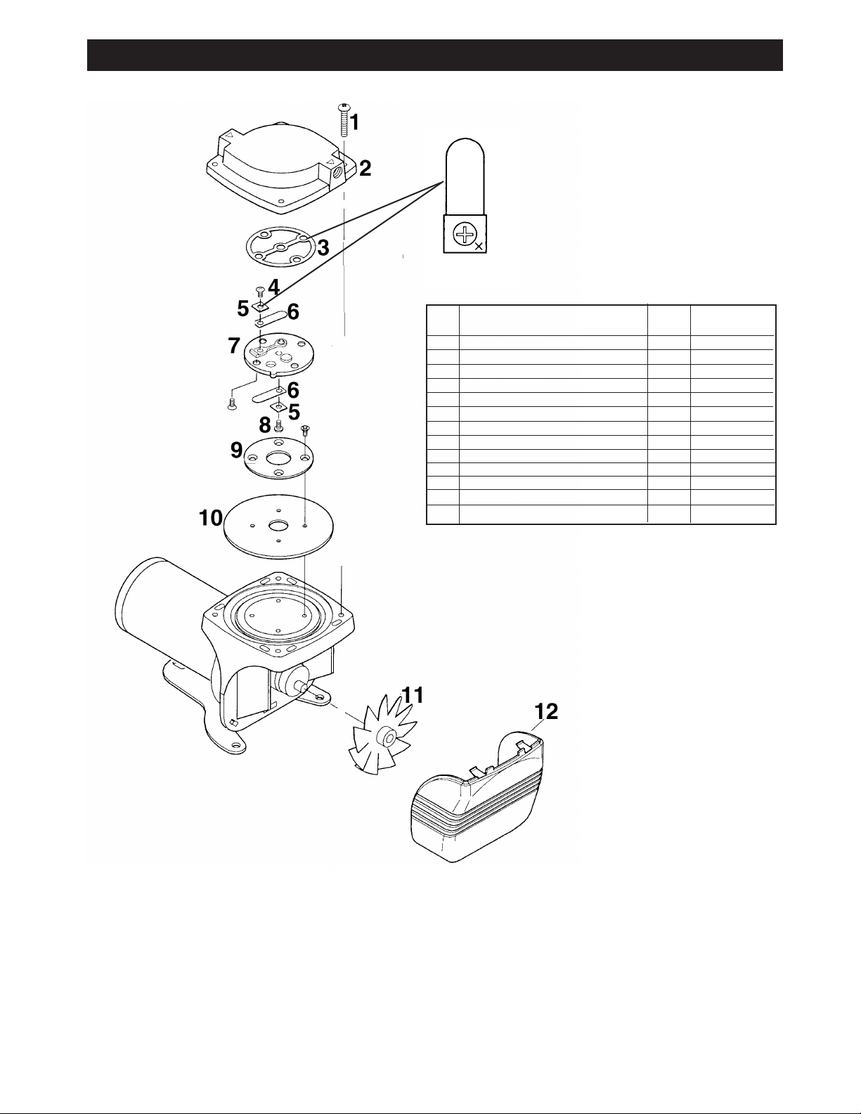
XPLODED PRODUCT VIEW, PARTS & ORDERING INFORMATION
E
REF DESCRIPTION QTY 22D
HEAD SCREWS 4 SCR1001
1
2 HEAD 1 HDC1003
3 ∆ HEAD GASKET 1 ACC1018
∆ INTAKE VALVE SCREW 1 SCR1017
4
5 ∆ RETAINER VALVE 2 AF819A
∆ VALVE 2 AF795
6
7 VALVE PLATE 1 VPL1003
8 ∆ EXHAUST VALVE SCREW 1 SCR1015
RETAINER PLATE 1 RPL1003
9
0 DIAPHRAGM (NEOPRENE MATERIAL) 1 DPH1001
1
11 FAN 1 ACC1001
12 GRILLE 1 CVR1001
*** SERVICE KIT 1 K707
*** Item not shown.
∆ Denotes parts included in the Service Kit.
Parts listed are for stock models. For specific OEM models,
please consult the factory.
When corresponding or ordering parts, please give complete
model and serial numbers.
Page 8
www.gastmfg.com
ISO 9001 & 14001 CERTIFIED
ART NO. 70 - 6900 G497PL (REV-H)
P
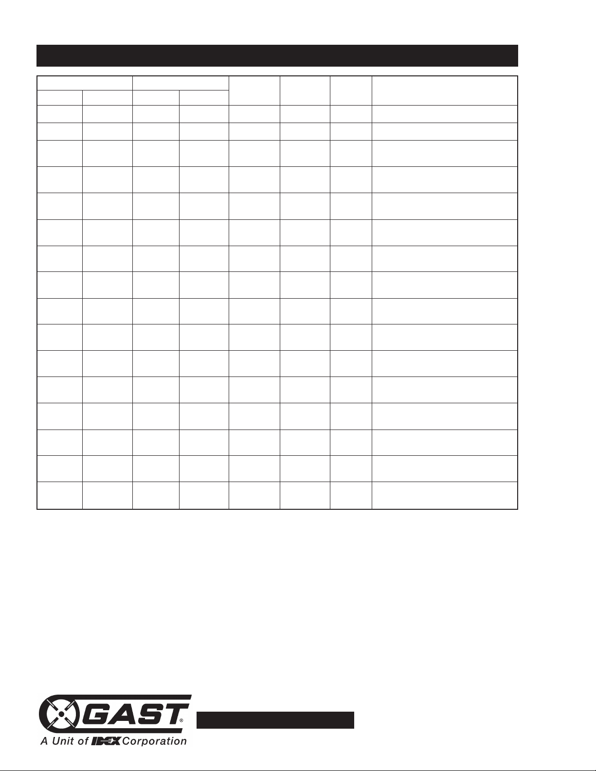
TROUBLESHOOTING CHART
Low High Pump Won’t Excess Reason and remedy
Vacuum Pressure Vacuum Pressure Overheat Start Noise for problem.
••• • • Filter dirty. Clean or replace.
•• • • • Muffler dirty. Clean or replace.
•• Valves dirty or valves bent.
Clean or replace.
•• Worn cup.
Repair or replace.
••• Relief valve set too high.
Inspect and adjust.
•• Relief valve set too low.
Inspect and adjust.
•••• • • Plugged vacuum/pressure line.
Inspect and repair.
•• Collapsed vacuum line.
Inspect and repair.
•• Low voltage, wonʼt start.
Check power source.
•••Voltage wrong.
Check power source.
•• •Worn cup/piston hitting cylinder.
Replace.
••Cylinder misadjustment.
Realign.
•• • Leaky hose or check valve.
Replace.
•• • ••Dirt or liquid on top of piston.
Inspect and clean.
•• • ••Motor not wired correctly.
Check wiring diagram/line voltage.
•• •Blown head gasket.
Replace.
For repair parts ordering information and exploded product view, visit our website or
call us at the number listed below.
We have Gast Authorized Repair Facilities throughout the world. For the most up-to-
Gast Manufacturing, Inc.
2300 S. Highway M139
Benton Harbor, MI,49022
Ph: 269/926-6171
FAX: 269/925-8288
www.gastmfg.com
Gast Hong Kong
Unit 12, 21/F, Block B
New Trade Plaza
6, On Ping Street, Shatin
N. T. Hong Kong
Ph: (852) 2690 1066
Fax: (852) 2690 1012
www.gasthk.com
European Sales & Service
Headquarters
Gast Group Limited
A Unit of IDEX Corporation
Unit 11, The I O Centre
Nash Road
Redditch B98 7AS
United Kingdom
Tel: +44 (0) 1527 504040
Fax: +44 (0) 1527 525262
www.gastmfg.com
www.jun-air.com
 Loading...