

Page 1
OPERATION & MAINTENANCE
70-5200 G480PL (Rev.C)
Laboratory Rocking Piston
Vacuum Pump and Compressor
ROA Series
USER INSTRUCTIONS
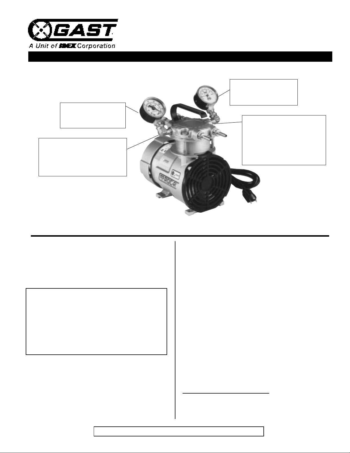
Pressure Gauge
The pressure gauge shows
the output pressure.
Pressure Regulator
Turn the regulator screw clockwise
to increase pressure (up to approximately 100 PSI max. with the screw
turned fully to the end stop).
Vacuum Gaug e
The vacuum gauge shows
the inlet vacuum.
Vacuum Regulator
Turn the regulator screw clockwise
to increase vacuum (up to approximately 25” Hg max. with the screw
turned fully to the end stop).
Note: Maximum pressure and vacuum
cannot be produced at the same time.
This is the hazard alert symbol: m When you see
this symbol, be aware that personal injury or property
damage is possible. The hazard is explained in the
text following the symbol. Read the information
carefully before proceeding.
The following is an explanation of the three
different types of hazards:
m DANGER Severe personal injury or death
will occur if hazard is ignored.
m WARNING Severe personal injury or death
can occur if hazard is ignored.
m CAUTION Minor injury or property damage
can occur if hazard is ignored.
GENERAL INFORMATION
This pump is designed to be used for the purpose of
pumping air. The pump should not be used for the
pumping of fluids, particles, solids or any combustible substances likely to cause explosions.
m DANGER Do not pump flammable or explosive
gases or operate the unit in an atmosphere containing them.
m CAUTION The pump is designed for pumping air.
Do not allow corrosive gases or
particulate material to enter the pump.
Water, oil-based contaminants, or
other liquids must be filtered out.
m CAUTION Normal ambient temperature should
not exceed 400 C (1040 F). For
operation at higher temperatures,
consult the factory.
m WARNING Exhaust air temperature can be-
come very hot. Keep away from air
stream.
Performance is reduced by low atmospheric pressure found
at high altitudes. Consult a Gast distributor for details.
Never lubricate this oil-less pump. Most components are
made of aluminum and the valves are stainless steel.
KEEP THIS DOCUMENT FOR FUTURE REFERENCE
Page 2
INSTALLATION
m WARNING To avoid risk of electrocution do not
use this product in an area where it
could come in contact with water or
other liquids. If exposed to the elements, it must be weather protected.
m CAUTION Do not block the flow of cooling air
over the pump in any way.
Mounting the Pump
m CAUTION Remove the plastic plugs in the
intake and exhaust ports before
operating unit.
The pump may be installed in any orientation as long as
the flow of cool, ambient air over the pump is not
blocked. To reduce noise and vibration, use shock mounts
and affix to a stable, rigid operating surface.
Plumbing
To prevent air flow restriction, use pipe and fittings that
are the same size or larger than the threaded ports of the
pump. NOTE: Be sure to connect the intake and exhaust
plumbing to the correct inlet and outlet ports.
Accessories
Filters and mufflers are supplied on some models. Check
periodically and replace when necessary. Consult a Gast
Representative for filter recommendations. For best
results, install relief valves and gauges at the inlet or
outlet, or both, to monitor performance.
Relief Valve
m WARNING Do not touch relief valve as it becomes
very hot during operation and will burn
skin on contact. Wait until unit has
been turned off and allowed to cool
before touching it.
A safety relief valve is provided on standard
compressors and is preset at factory. Do not exceed
or adjust safety relief to pressures other than those
preset at factory.
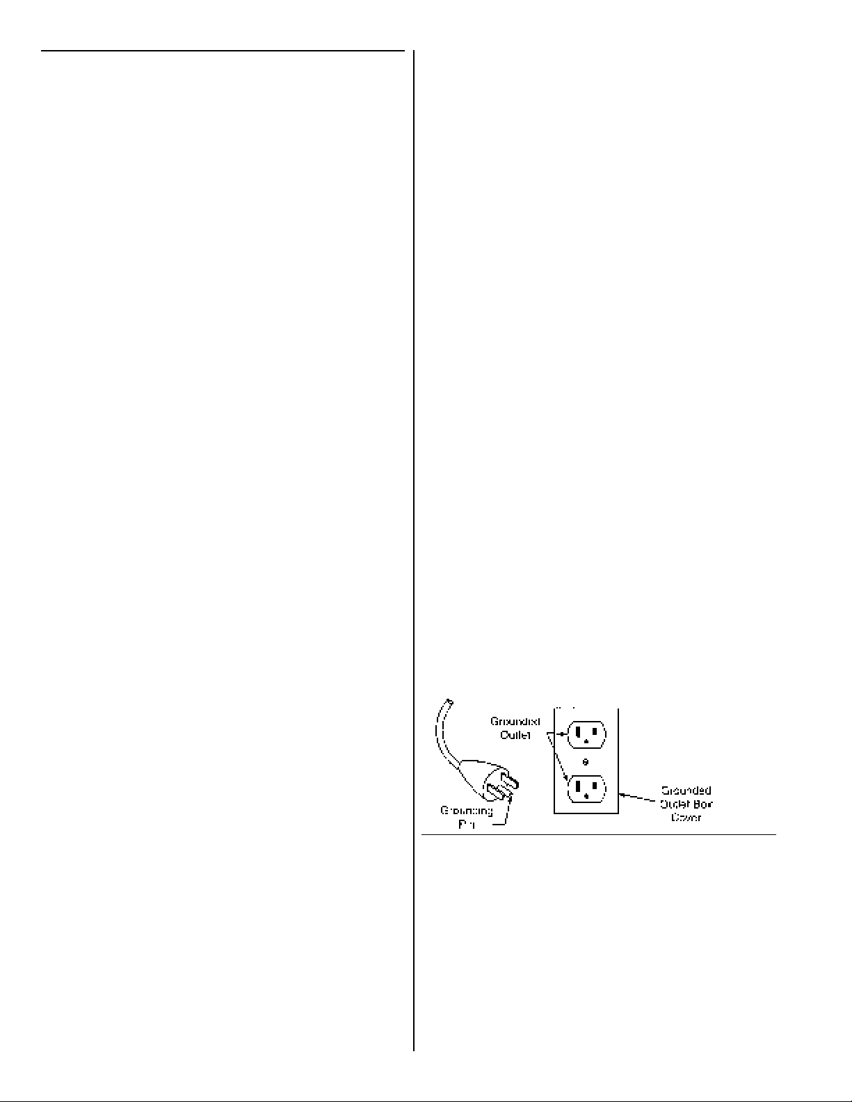
Grounding Instructions
Check with a qualified electrician or serviceman if
the grounding instructions are not completely understood, or if in doubt as to whether the product is
properly grounded. Do not modify the plug provided; if it will not fit the outlet, have the proper
outlet installed by a qualified electrician.
For All Grounded, Cord-connected Products:
This product should be grounded. In the event of an
electrical short circuit, grounding reduces the risk of
electric shock by providing an escape wire for the electric
current. Some units are equipped with a cord having a
grounding wire with an appropriate grounding plug. The
plug must be plugged into an outlet that is properly
installed and grounded in accordance with all local codes
and ordinances.
m DANGER Improper installation of the ground-
ing plug can result in a risk of electric
shock.
If repair or replacement of the cord or plug is necessary,
do not connect the grounding wire to either flat blade
terminal. The wire with insulation having an outer
surface that is green, with or without yellow stripes, is the
grounding wire.
For A Grounded, Cord-connected Product Rated
Less Than 15 Amperes And Intended For Use On A
Nominal 120v, Or 220-240 Volt Supply Circuit:
This product is for use on a nominal 120v, or 220240 volt circuit, and has a grounding plug. Make
sure that the product is connected to an outlet having
the same configuration as the plug. No adapter
should be used with the product.
m WARNING Do not unscrew relief valve head
entirely off while unit is operating.
Ejecting valve parts could cause
severe injury.
Wiring
m WARNING Incorrect wiring can result in electric
shock. Wiring must conform to all
required safety codes and be
installed by a qualified person.
m WARNING All power to the motor must
be de-energized and disconnected
when servicing.
OPERATION
mWARNING Solid or liquid material exiting the
unit can cause eye or skin damage.
Keep away from air stream.
mWARNING Always disconnect the power before
servicing. The motor may be ther
mally protected and will restart
automatically when it cools if the
thermal protection switch is tripped.
Page 3
mWARNING The head surface(s) can be very hot
depending on pump duty and speed.
Do not touch these parts during
operation.
m CAUTION Do not operate these units above
25 in. Hg vacuum or 100 PSIG
pressure (45 PSIG intermittent). To
do so will damage the unit.
mWARNING Do not operate without the grille(s), if
provided, in place. Failure to do so
could result in severe personal injury.
Starting
m CAUTION Do not start against a vacuum or
pressure load.
If the pump is extremely cold, let it warm up to room
temperature before starting. If the pump does not operate
properly, see the troubleshooting guide.
Shutdown Procedure Conti.
1. NEVER oil this non-lubricated pump.
2. After using the pump, disconnect plumbing and allow
the pump to run "open" for at least 5 minutes before
shutdown.
3. Plug the open ports to prevent dirt or other
contaminents from entering the pump. It is now ready
for shutdown or storage.
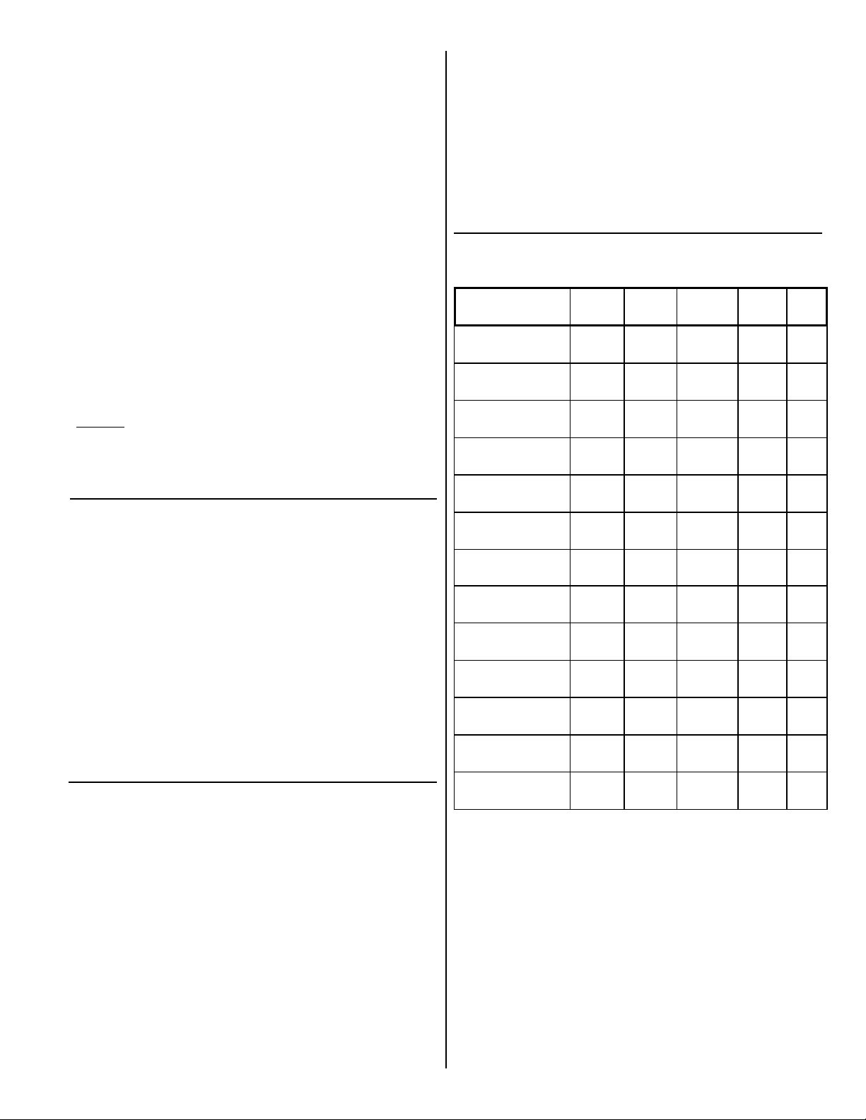
TROUBLESHOOTING GUIDE
Possible Reason
Dirty Filter X X
Dirty Muffler X X
Low
Pressure
Low
Vacuum
Excessive
Noise
Over-
heating
Won't
Start
NOTE: Some of these models may exceed
70 dB(A). When in close proximity to these models
hearing protection is required. Refer to the Techni
cal Data Sheet for your specific model.
MAINTENANCE AND INSPECTION
Intake filter and mufflers require periodic inspection and
replacement. Initial inspection is suggested at 500 hours,
then the user should determine the frequency thereafter.
Most problems can be prevented by keeping filters and
mufflers clean. Dirty filters and mufflers decrease pump
performance and can decrease pump life.
Filter Inspection and Replacement
The head surface(s) on some models can be very hot
during operation. Do not touch these parts until the
pump has been turned off and allowed to cool. Some
filter element(s) are held together by a snap fit. Remove
the cover to replace the felt, and reassemble.
SHUTDOWN PROCEDURES
Proper shutdown procedures must be followed to prevent
pump damage. Failure to do so may result in premature
pump failure. The Gast Manufacturing non-lubricated
vacuum pumps and compressors are constructed of
ferrous metals or aluminum which are subject to rust and
corrosion when pumping condensable vapors such as
water. Follow the steps below to assure correct storage
and shutdown between use:
Dirty Valves X X
Bent Valves X X
Damaged Cup X X
Low Voltage X X X X
Wrong voltage X X X
Pressure on Head X
Improper Cylinder
Shimming
Relief Valve Set
Too High
Relief Valve Set
Too Low
Leaky Hose X X
Leaky Check
Valve
XX
XX
X
Service Kit(s) and repair instructions are available
upon request. Contact your local Represetative,
Distributor, or the factory for details.
NOTE: Gast will not guarantee the performance of
a field rebuilt pump. You can return the pump to an
Authorized Service Facility listed on the back page.
X
Page 4
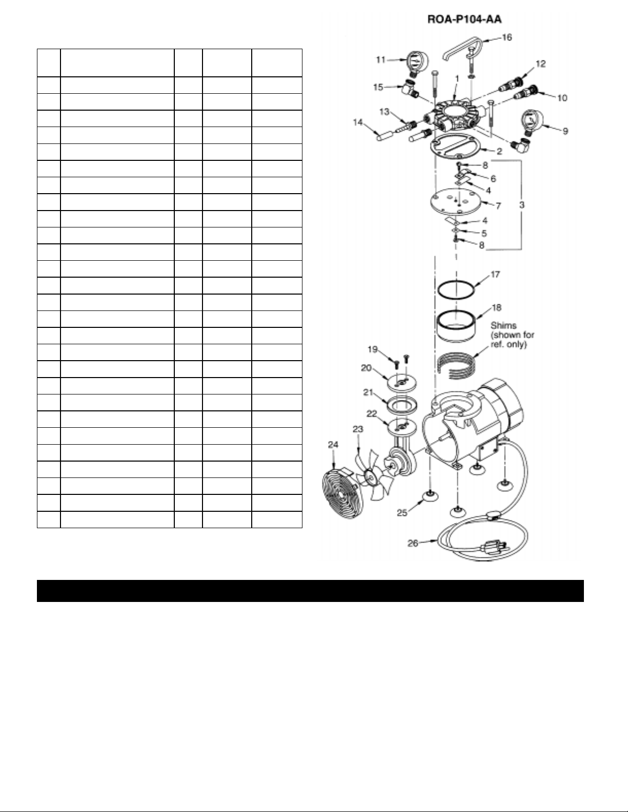
Ref.
No.
Description
Part
ROA-P231 ROA-P204
Qty.
1 Head 1 AJ347 AJ347
*2 Head Gasket 1 AJ404A AJ404A
*3 Valve Plate Assembly 1 AJ343A AJ343A
4 Leaf Valve 2 AF817 AF817
5 Valve Retainer 1 AF819A AF819A
6 Valve Limiter 1 AF856 AF856
7 Valve Plate 1 AJ344 AJ344
8 Screw 1 BB317 (2) BB317 (2)
9 Pressure Gauge 1 AF583 AE362
10 Pressure Regulator 1 AF887 AF887
11 Vacuum Gauge 1 AA640 AA640
12 Vacuum Regulator 1 AA550C-V AA550G-V
13 Hose Nipple 2 AA254D AF431
14 Cap 2 AG491 AG491A
15 Elbow 2 BA204A BA204A
16 Handle 1 AC174 AC174
*17 O-Ring, Cylinder 1 AH179 AH179
18 Cylinder 1 AJ342 AJ342
19 Screw 2 BB557 BB557
20 Retainer Plate 1 AH177 AH177
*21 Cup 1 AH175 AH175
22 Connecting Rod Assembly 1 AH173 AH173
23 Fan 1 AF533 AF533
24 Grille 1 AH185 AH185
25 Rubber Foot Support 4 AF584A AF584A
26 Cord/Switch/Plug 1 AF968 AF968
Service Kit 1 K757 K757
*Denotes parts included in the service kit.
When corresponding or ordering parts please give complete
model and serial numbers.
AUTHORIZED SERVICE FACILITIES
Gast Manufacturing Inc. Brenner Fiedler & Assoc. Gast Manufacturing Co., Ltd
505 Washington Ave 13824 Bentley Place Beech House, Knaves Beech
Carlstadt, NJ 07072 Cerritos, CA 90701 Business Centre, Loudwater
TEL: 201-933-8484 TEL: 800-843-5558 High Wycombe, Bucks HP 10 9SD
FAX: 201-933-5545 TEL: 310-404-2721 England
FAX: 310-404-7975 TEL: 44 628 532600
FAX: 44 628 532470
Wainbee Limited Wainbee Limited Japan Machinery Co. Ltd. NOTE: General Correspondence
215 Brunswick Blvd. 5789 Coopers Avenue Central PO Box 1451 should be sent to—
Pointe Claire, Quebec Mississauga, Ontario Tokyo, 100-91 Japan Gast Mfg. Inc./A Unit of IDEX Corporation
Canada H9R 4R7 Canada L4Z 3S6 TEL: 81-3-3573-5421 P O Box 97
TEL: 514-697-8810 TEL: 416-213-7202 FAX: 81-3-3571-7865 Benton Harbor, MI 49023-0097
FAX: 514-697-3070 FAX: 416-213-7207 or: 81-3-3571-7896
 Loading...