

Page 1
www.gastmfg.com
ISO 9001 & 14001 CERTIFIED
®Registered Trademark/™Trademark of Gast Manufacturing Inc., Copyright © 2003 Gast Manufacturing Inc. All Rights Reserved.
ART NO. 45-115 D150B (Rev. N)
P
NL SERIES NON-LUBRICATED AIR MOTORS
OPERATION & MAINTENANCE MANUAL
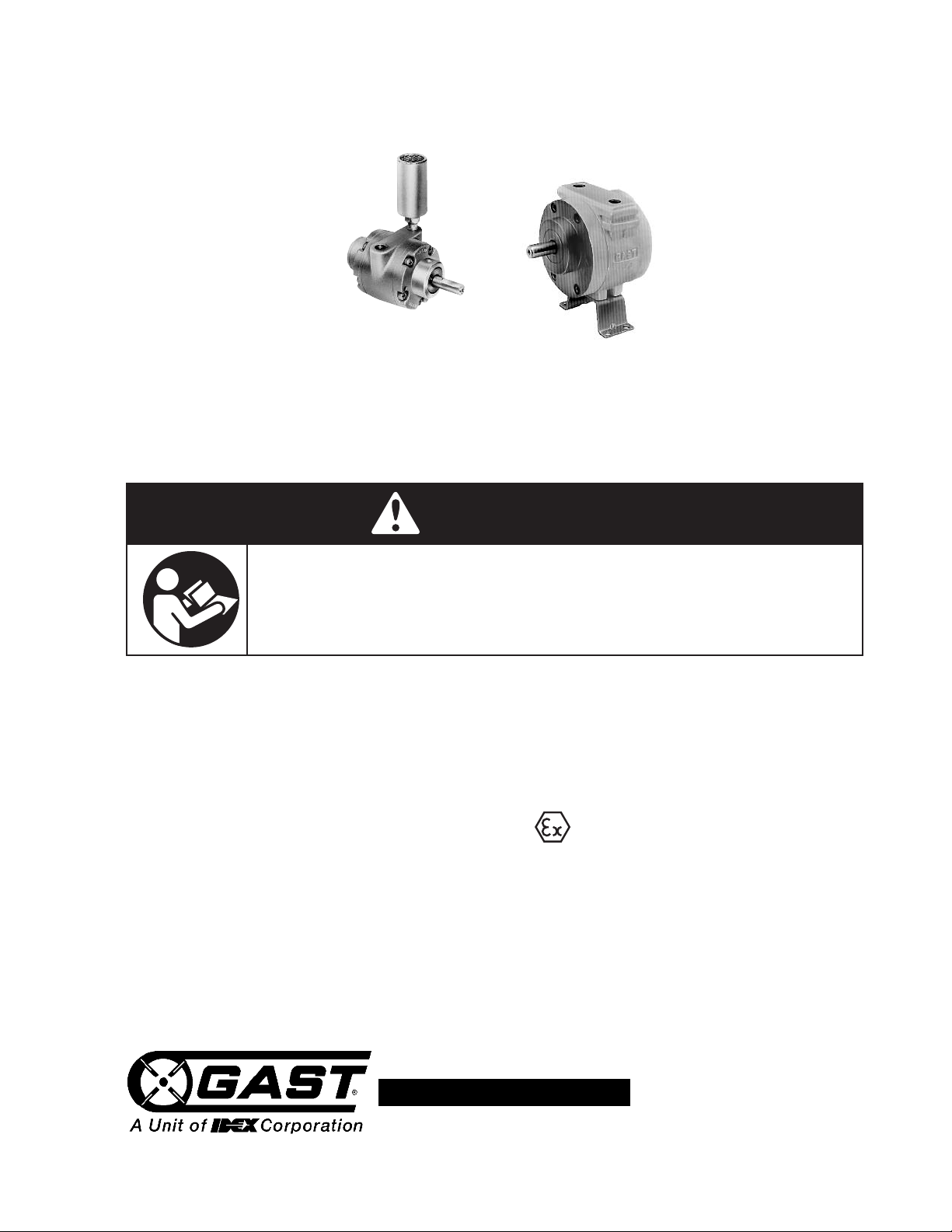
Model NL22 Shown
Thank you for purchasing this Gast product. It is manufactured to the highest standards
using quality materials. This manual includes general safety instructions for operation under normal
conditions and for operation in hazardous conditions. Please follow all recommended maintenance,
operational and safety instructions and you will receive years of trouble free service.
Model NL32 Shown
WARNING
PLEASE READ THIS MANUAL COMPLETELY BEFORE INSTALLING AND USING
THIS MOTOR. SAVE THIS MANUAL FOR FUTURE REFERENCE AND
KEEP IN THE VICINITY OF THE MOTOR.
General information:
Operating Pressure: 80 psi or below (7 bar)
Product Use Criteria:
•Normal conditions: Operate at temperatures up to
250ºF (121ºC).
•Hazardous conditions: Operate at temperatures up to
104ºF (40ºC).
• Protect unit from dirt and moisture.
•Use ONLY compressed air to drive motor.
•Air lines connected to motor should be the same size or
the next size larger than the inlet port for efficient
output and speed control.
•Protect all surrounding items from exhaust air.
•Bearings are grease packed.
• Motors are to be used in commercial installations only
• This symbol appears on labels of air motors
that are designed for use in hazardous
atmospheres. These air motors comply with the
applicable standards and specifications and meet
the requirements of the guidelines of the EC
directive 94/9EC (ATEX 100a). They are intended to
be used in zones 1 and 2 where explosive
atmospheres are likely to occur.
• Air supply, directional control valve and pressure
regulator
should be selected based upon the air consumption
of the motor.
1
Page 2
Your safety and the safety of others
is extremely important.
e have provided many important safety messages in
W
this manual and on your product. Always read and
obey all safety messages.
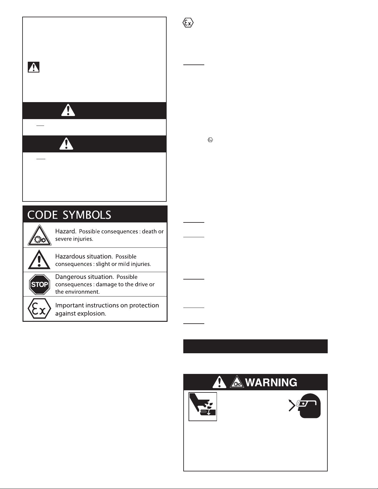
his is the safety alert symbol. This symbol
T
alerts you to hazards that can kill or hurt you and
others. The safety alert symbol and the words
“DANGER”and “WARNING”will precede all safety
essages. These words mean:
m
DANGER
e killed or seriously injured if you don’t follow
b
ou will
Y
instructions.
WARNING
You can
instructions.
All safety messages will identify the hazard, tell you
how to reduce the chance of injury, and tell you what
can happen if the safety instructions are not followed.
be killed or seriously injured if you don’t follow
Complete the following checklist prior to
starting installation in a hazardous area. All
actions must be completed in accordance with ATEX
100a.
Checklist for installation in hazardous areas:
Read air motor label to check that
motor has been designed for use
in a hazardous application:
• Hazardous zone
• Hazardous category
• Equipment group
• Temperature class
• Maximum surface temperatures
Example:
Model designation: 1UP-NRV-10
Year manufactured: 2003
Gast Mfg. Corp.
II 2GD c +1Cº Ta +40Cº
Benton Harbor, MI USA
Telephone: 269.926.6171
* Legend:
II Equipment group II
2 Equipment category 2
G Gas atmospheres
D Dust atmospheres
c Constructional safety
+1CTa +40C* Max. surface temp. 275ºF/135ºC
Ambient range +1Cº to +40ºC (34ºF/104ºF)
Check the site environment for potentially
explosive oils, acids, gases, vapors or radiation
Check the ambient temperature of the site and
the ability to maintain proper ambient
temperature.
Ambient range:
Normal conditions: 34ºF/1ºC to 250ºF/121ºC
Hazardous conditions: 34ºF/1ºC to 104ºF/40ºC
Check the site to make sure that the air motor
will be adequately ventilated and that there is no
external heat input (e.g. couplings). The cooling
air may not exceed 104ºF/40ºC.
Check that products to be driven by the air
motor meet ATEX approval.
Check that the air motor is not damaged.
Improper environment, installation and operation can
result in severe personal injury and/or damage to
property.
Qualified personnel must perform all work to assemble,
install, operate, maintain and repair air motor.
Qualified personnel must follow:
• These instructions and the warning and information
labels on the motor.
• All other drive configuration documents, startup
instructions and circuit diagrams.
• The system specific legal regulations and
requirements.
• The current applicable national and regional
specifications regarding explosion protection,
safety and accident prevention.
2
INSTALLATION
Correct installation is your responsibility. Make sure you
have the proper installation conditions.
Injury Hazard
Install proper guards around output shaft as needed.
Air stream from product may contain solid or liquid
material that can result in eye or skin damage.
Wear proper eye protection when installing this product.
Failure to follow these instructions can result in
serious injury or property damage.
Page 3
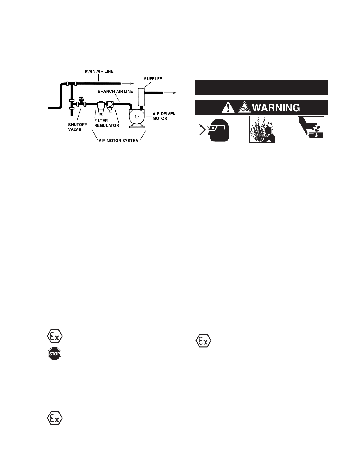
Mounting
This product can be installed in any orientation. Mount
the motor to a solid metal base plate that is mounted to
stable, rigid operating surface. Use shock mounts to
a
reduce noise and vibration. Install a pressure regulator
or simple shut-off valve to control motor.
Accessories
A muffler is shipped with the air motor (except 16AM)
but is not installed. Consult your Gast
Distributor/Representative for additional filter
recommendations. Install a moisture trap and 5 micron
filter in the air line ahead of motor.
Connection
Check the direction of the motor airflow. A single
rotation motor will operate properly only in one
direction.
Single rotation motors require a sound absorber to be
connected to the exhaust air port. Remove the plastic
shipping plugs from the ports. Save plugs for future
use during shutdown.
Install a 5-micron filter in the air line before the
connection to the motor. Next install an air pressure
regulator to control motor speed and torque.
Clean the compressed air connection with low pressure
air to remove any dirt from the line before connecting to
the ports.
Use the proper sized fasteners. For the most efficient
output and control of speed, use air lines that are the
same size as the motor inlet port if the connection is
less than 7 feet (2 meters). For longer connections, use
the next pipe size larger than the motor intake port.
Connect lines to motor in the proper direction.
Air consumption data at various speeds and pressures
are available from your Gast Distributor/Representative
r the factory.
o
OPERATION
Injury Hazard
Air stream from product may contain solid or liquid
material that can result in eye or skin damage.
DO NOT use combustible gases to drive this motor.
Wear hearing protection. Sound level from motor
may exceed 85 db(A).
Failure to follow these instructions can result in
burns, eye injury or other serious injury.
Check all connections before starting motor. It is your
responsibility to operate this product at recommended
speeds, loads and room ambient temperatures. Do not
run the motor at high speeds with no load. This will
result in excessive internal heat that may cause motor
damage.
The starting torque is less than the running torque. The
starting torque will vary depending upon the position of
the vanes when stopped in relation to the air intake
port.
Connect the sound absorber on the exhaust air port or
valve connection.
Do not add any thrust to the end or side of the shaft
when making connections.
Do not use a hammer on the shaft or
connections.
Lubricating the drive shaft will make assembly
easier. Use a puller for removal of pulleys,
couplings and pinions on the motor shaft.
Check that the tension on the belt pulley
matches the manufacturer’s specifications. Do not
exceed the maximum radial and axial forces on the
shaft. If the motor shaft is connected to the part to be
driven without a coupling, check that the radial offset
and axial force effect will not cause problems.
Use only belts with < 109electrical leakage
resistance to prevent static electrical problems.
Ground the motor.
Use a pressure regulator and/or simple shut-off valve to
regulate the motor’s speed and torque. This will
provide the required power and will conserve air. Open
the air supply valve to the motor. Set the pressure or
flow rate to the required speed or torque.
Operate the motor for approximately 2 hours at
the maximum desired load. Measure the
surface temperature of the motor on the casting
opposite the pipe ports. The maximum surface
temperature listed on the motor is for normal
environmental and installation conditions. For most air
motors, the maximum surface temperature should not
exceed 266ºF /130ºC. Do not continue to operate the
motor if the measured surface temperature exceeds
temperature listed on the motor. If your measured
temperature does exceed listed value, consult with your
Gast Distributor/Representative for a recommendation.
3
Page 4
MAINTENANCE
Injury Hazard
isconnect air supply and vent all air lines.
D
ear eye protection when flushing this product.
W
Air stream from product may contain solid or liquid
material that can result in eye or skin damage.
Flush this product in a well ventilated area.
DO NOT use kerosene or other combustible solvents
to flush this product.
Failure to follow these instructions can result in
burns, eye injury or other serious injury.
It is your responsibility to regularly inspect and make
necessary repairs to this product in order to maintain
proper operation.
4. Check the air compressor.
5. Listen for changes in the sound of the motor.
If motor sounds smooth, you are finished.
If motor does not sound like it running smoothly,
installing a service kit will be required
(See “Service Kit Installation”).
Shutdown
It is your responsibility to follow proper shutdown
procedures to prevent product damage.
1. Turn off air intake supply.
2. Disconnect air supply and vent all air lines.
3. Disconnect air lines.
. Remove air motor from connecting machinery.
4
5. Remove the muffler.
6. Wear eye protection. Keep away
from air stream. Use clean, dry air
to remove condensation from the inlet port of
the motor.
7. Plug or cap each port.
8. Coat output shaft with oil or grease.
9. Store motor in a dry environment.
SERVICE KIT INSTALLATION
Check intake and exhaust filters after first 500 hours of
operation. Clean filters and determine how frequently
filters should be checked during future operation. This
one procedure will help assure the motor’s performance
and service life.
Flushing
Flushing this product to remove excessive dirt, foreign
particles, moisture or oil that occurs in the operating
environment will help to maintain proper vane
performance. Flush the motor if it is operating slowly
or inefficiently.
Use only Gast recommended Flushing Solvent.
DO NOT use kerosene or ANY other combustible
solvents to flush this product.
1. Disconnect air line and muffler.
2. Add flushing solvent directly into motor. If using
liquid solvent, pour several tablespoons directly
into the intake port. If using spray solvent,
spray for 5-10 seconds into intake port.
3. Rotate the shaft by hand in both directions for a
few minutes.
4. You must wear eye protection for this step.
Cover exhaust with a cloth and reconnect the air
line.
5. Restart the motor at a low pressure of
approximately 10 PSI/ 0.7 bar until there is no
trace of solvent in the exhaust air.
6. Listen for changes in the sound of the motor.
If motor sounds smooth, you are finished.
If motor does not sound like it is running smoothly,
installing a service kit will be required
(See “Service Kit Installation”).
Check that all external accessories such as relief valves
or gauges are attached and are not damaged before
operating product.
Cleaning sound absorber
1. Remove the sound absorber.
2. Clean the felt filter.
3. You must wear eye protection for this step.
4
Gast will NOT guarantee field-rebuilt product
performance. For performance guarantee, the product
must be returned to a Gast Authorized Service Facility.
Service Kit contents vary. Most contain vanes, end cap
gasket, body gasket, bearings and a muffler element or
felt.
Major and Minor Rebuilds Tool kits which include a
more in-depth rebuild manual are available through your
Gast Distributor/Representative. These kits include the
tools required to remove and reassemble end plates,
bearings and shaft seals, and to set the proper end
clearance. The rebuild manual also includes step by
step instructions, including illustrations, to help achieve
a successful rebuild. Gast Manufacturing, Inc. highly
recommends using the air motor rebuild manual and
tool kit when attempting a minor or major rebuild to
your Gast air motor.
Minor Rebuild:
1. Remove the end cap.
2. Remove dead end plate bolts.
3. Remove dead end plate. (Use factory issued tool,
do not use screwdriver to remove the end plate.)
4. Remove the dowel pins from the body and push
back into end plate until flush or just below the
machined surface of the end plate.
5. Remove vanes.
6. Clean parts. Check for scoring on the end plate
and rotor assembly. If scoring exists, send unit to
a Gast authorized service facility.
7. Install vanes. Angle cuts on vanes face to
center of rotor.
8. Place the proper end plate gasket on the end
plate. If the original is damaged, replace with a
new one supplied in the Service Kit.
9. Place the dead end plate on the body.
10. Press the bearing onto the shaft using a factory
supplied bearing pusher.
Page 5

11. Tap dowel pins into body and install end plate
olts. Tighten bolts.
b
12. Set end clearance as required by model:
NL22-NL52 models - use the bearing taper from
the Tool Kit to lightly tap on the inner race of the
ead end bearing to free up and center the rotor
d
in the body.
13. Reattach end cap.
Major Rebuild:
1. Remove the end cap.
2. Remove dead end plate bolts.
3. Remove dead end plate. (Use factory issued tool,
do not use screwdriver to remove the end plate.)
4. Remove the dowel pins from the body and push
back into end plate until flush or just below the
machined surface of the dead end plate.
5. Remove rotor using an arbor press.
6. Remove vanes and ejection mechanism if
reversible. (Ejection mechanisms may consist of
vane springs, pins, caps or cam rings.)
7. Remove shaft seal and bearings from drive end
plate and bearing from dead end plate. (Use
factory issued tool.)
8. Do Not remove drive end plate bolts or drive end
plate.
9. Clean parts. Check for scoring on the end plates
and rotor assembly. If scoring exists, send unit to
a Gast Authorized Service Facility.
10. Place the drive shaft of the rotor assembly
through the drive end plate.
Press the drive bearing onto
the drive shaft using a factory supplied bearing
pusher.
11. Using the bearing taper from the Tool Kit, lightly
tap on inner race of the drive end bearing to snug
up rotor to drive end plate.
12. Install new vanes as required by model:
All single rotation units - the angle cuts on the
vane face to center of the rotor.
13. Place the proper end plate gasket on the body of
dead end. If the original is damaged, replace
with a new one supplied in the service kit.
If your air motor uses O-rings, place the new
O-rings in the body groove. Some models do not
use end plate gaskets or O-rings.
14. Place the dead end plate on the body.
15. Install the dead end bearing and press into place
with bearing pusher tool from tool kit.
16. Install the dowel pins.
17. Fully tighten the remaining bolts.
18. Set end clearance as required by model:
NL22-NL52 models - use the bearing taper from
the Tool Kit to lightly tap on the inner race of the
dead end bearing to free up and center the rotor
in the body.
19. Apply a small amount of grease to bearing seal
and install the drive end bearing seal by pressing
flush with bearing pushing tool from Tool Kit.
20. Reattach end cap.
Disposal (Please note current regulations)
Parts of the air motor or air powered gear motor,
shafts, cast iron or aluminum castings, gear
wheels as well as rolling contact bearings may
be recycled as scrap metal.
5
Page 6
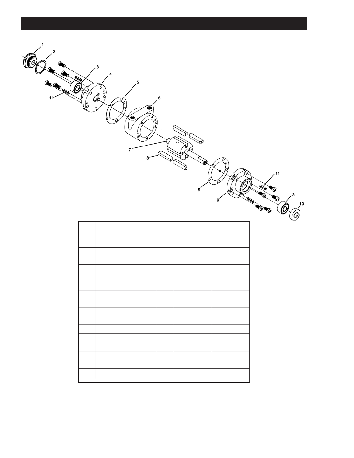
EXPLODED PRODUCT VIEW, PARTS & ORDERING INFORMATION 22 S ERIES
22 SERIES
REF# DESCRIPTION QTY NL22-NCW-2 NL22-NCC-1
NL22-FCW-4* NL22-FCC-3*
1 END CAP 1 AC228A AC228A
2 ∆ END CAP GASKET` 1 AC229 AC229
3 ∆ BEARING 2 AG549 AG549
4 DEAD END PLATE 1 AC192A AC617
5 ∆ BODY GASKET
(PRE 1998 MODELS) 2 AC527B AC527B
6 BODY 1 AE899A AE899A
7 ROTOR ASSEMBLY 1 AL335 AL334
8 ∆ VANES 4 AL306 AL306
9 DRIVE END PLATE 1 AC520B AC616
10 ∆ SEAL 1 AC190A AC190A
11 DOWEL PINS 1 D324A D324A
*** MUFFLER ASSEMBLY 1 AF350 AF350
*** ∆ MUFFLER ELEMENT 1 AG896 AG896
*** SERVICE KIT 1 K285A K285A
*** FOOT ASSEMBLY 1 AG585 AG585
* Denotes model(s) that are supplied with Foot Assembly
*** Item not shown.
Parts listed are for stock models. For specific OEM models, please consult the factory.
∆ Denotes parts included in the Service Kit.
When corresponding about or ordering parts, please give complete model and serial numbers.
Exploded views are shown for reference only. Units may vary depending upon specific model.
6
Page 7
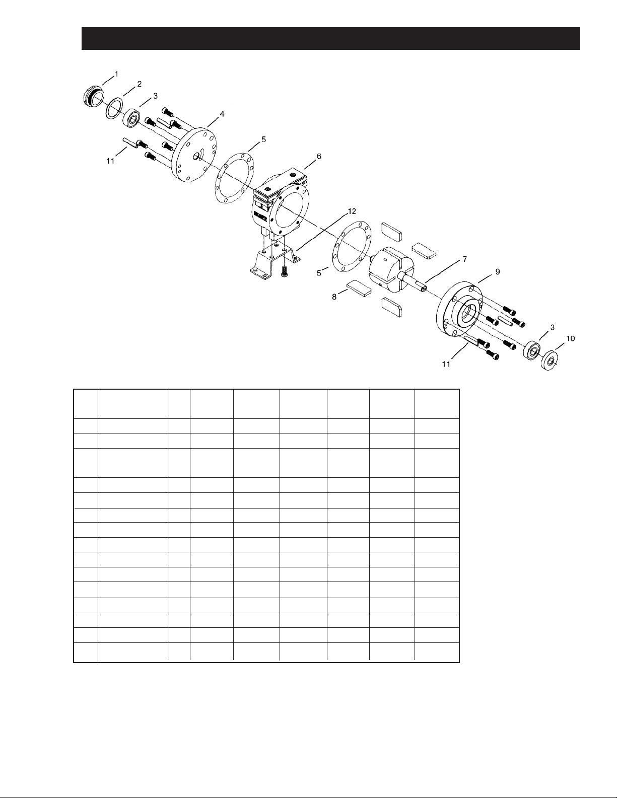
EXPLODED PRODUCT VIEW, PART S & ORDERING INFORMATION 31 & 32 SERIES
31 & 32 SERIES
REF# DESCRIPTION QTY NL32-NCC-1 NL32-NCW-2 NL32-NCC-5 NL32-NCW-6 NL32-NCC-7 NL32-NCW-8
1 END CAP 1 AM307D AM307D AM307D AM307D AM307D AM307D
2 ∆ END CAP GASKET` 1 AA46 AA46 AA46 AA46 AA46 AA46
3 ∆ BEARING 2 AA299J AA299J (1) AA299J (1) AA299J (1) AA299J (1)AA299J
(1) AB519 (1) AB519 (1) AB519 (1)AB519
4 DEAD END PLATE 1 AK906 AK906A AK906 AK906A AK906 AK906A
5 ∆ GASKET 1 B330 B330 B330 B330 B330 B330
6 BODY 1 AK989G AK989G AK989G AK989G AK989D AK989D
7 ROTOR ASSEMBLY 1 AK324 AL325 AL404 AL405 AL326 AL327
8 ∆ VANES 4 AK988 AK988 AK988 AK988 AK988 AK988
9 DRIVE END PLATE 1 AL320 AL321 AL322 AL323 AL322 AL323
10 ∆ SEAL 1 AA466B AA466B B2328 B2328 B2328 B2328
11 DOWEL PINS 1 AB162 AB162 AB162 AB162 AB162 AB162***
*** MUFFLER ASSEMBLY 1 AC980 AC980 AC980 AC980 AC980 AC980
*** ∆ MUFFLER ELEMENT 1 AC983 AC983 AC983 AC983 AC983 AC983
*** FLANGE 1 AK905A AK905A AK905 AK905
*** SERVICE KIT 1 K521 K521 K522 K522 K522 K522
*** Item not shown
∆ Denotes parts included in the Service Kit.
Parts listed are for stock models. For specific OEM models, please consult the factory.
When corresponding about or ordering parts, please give complete model and serial numbers.
Exploded views are shown for reference only. Units may vary depending upon specific model.
7
Page 8
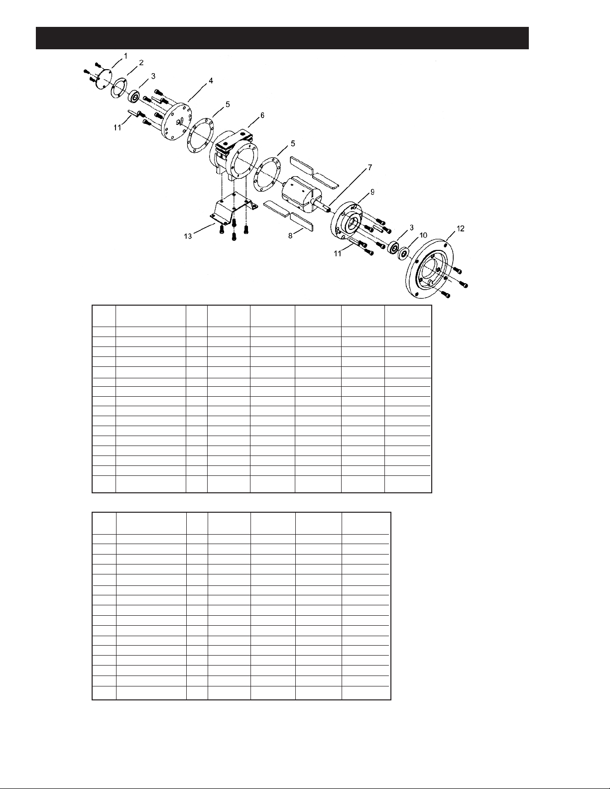
EXPLODED PRODUCT VIEWS, PARTS & ORDERING INFORMATION 42 & 52 SERIES
42 SERIES
EF# DESCRIPTION QTY NL42-NCC-1 NL42-NCW-2 NL42-NCC-5 NL42-NCW-6 NL42-NCC-7
R
1 END CAP 1 AD643 AD643 AD643 AD643 AD643
∆ END CAP GASKET` 1 AD644 AD644 AD644 AD644 AD644
2
3 ∆ BEARING 2 AB519 AB519 AB519 AB519 AB519
4 DEAD END PLATE 1 AL356 AL357 AL356 AL357 AL356
∆ GASKET 1 B300 B300 B300 B300 B300
5
6 BODY 1 AL305 AL305 AL305 AL305 AL305B
7 ROTOR ASSEMBLY 1 AL345 AL346 AL367 AL368 AL369
∆ VANES 4 AL165 AL165 AL165 AL165 AL165
8
9 DRIVE END PLATE 1 AL349 AL350 AL349 AL350 AL349
10 SEAL 1 B2328 B2328 B2328 B2328 B2328
11 DOWEL PINS 1 AB162 AB162 AB162 AB162 AB162
12 FLANGE 1 AK905A AK905A AK905
13 FOOT ASSEMBLY 1 AL414 AL414
*** MUFFLER ASSEMBLY 1 AC980 AC980 AC980 AC980 AC980
*** ∆ MUFFLER ELEMENT 1 AC983 AC983 AC983 AC983 AC983
*** SERVICE KIT 1 K580 K580 K580 K580 K580
52 SERIES
REF# DESCRIPTION QTY NL52-NCC-1 NL52-NCW-2 NL52-NCC-3 NL52-NCW-4
1 END CAP 1 AD643 AD643 AD643 AD643
2 ∆ END CAP GASKET` 1 AD644 AD644 AD644 AD644
3 ∆ BEARING 2 AB519 AB519 AB519 AB519
4 DEAD END PLATE 1 AL587A AL587 AL587A AL587
5 ∆ GASKET 1 B330F B330F B330F B330F
5 ∆ 1 B330G B330G B330G B330G
6 BODY 1 AL589 AL589 AL589 AL589
7 ROTOR ASSEMBLY 1 AL586A AL586 AL586A AL586
8 ∆ VANES 4 AL585 AL585 AL585 AL585
9 DRIVE END PLATE 1 AL588A AL588 AL588A AL588
10 ∆ SEAL 1 B2328 B2328 B2328 B2328
11 DOWEL PINS 1 AB162 AB162 AB162 AB162
12 FLANGE 1 AK905A AK905A
*** MUFFLER ASSEMBLY 1 AC990 AC990 AC990 AC990
*** ∆ MUFFLER ELEMENT 1 AC993 AC993 AC993 AC993
*** SERVICE KIT 1 K833 K833 K833 K833
* Denotes model(s) that are supplied with Foot Assembly
*** Item not shown.
Parts listed are for stock models. For specific OEM models, please consult the factory.
∆ Denotes parts included in the Service Kit.
When corresponding about or ordering parts, please give complete model and serial numbers.
8
Exploded views are shown for reference only. Units may vary depending upon specific model.
Page 9
G
ast finished products, when properly installed and operated under normal conditions of use, are warranted by Gast to
be free from defects in material and workmanship for a period of twelve (12) months from the date of purchase from
Gast or an authorized Gast Representative or Distributor. In order to obtain performance under this warranty, the buyer
must promptly (in no event later than thirty (30) days after discovery of the defect) give written notice of the defect to
Gast Manufacturing Incorporated, PO Box 97, Benton Harbor Michigan USA 49023-0097 or an authorized Service
Center (unless specifically agreed upon in writing signed by both parties or specified in writing as part of a Gast OEM
Quotation). Buyer is responsible for freight charges both to and from Gast in all cases.
This warranty does not apply to electric motors, electrical controls, and gasoline engines not supplied by Gast. Gast’s
warranties also do not extend to any goods or parts which have been subjected to misuse, lack of maintenance,
n
eglect, damage by accident or transit damage.
THIS EXPRESS WARRANTY EXCLUDES ALL OTHER WARRANTIES OR REPRESENTATIONS EXPRESSED OR
IMPLIED BY ANY LITERATURE, DATA, OR PERSON. GAST’S MAXIMUM LIABILITY UNDER THIS EXCLUSIVE
REMEDY SHALL NEVER EXCEED THE COST OF THE SUBJECT PRODUCT AND GAST RESERVES THE RIGHT,
AT ITS SOLE DISCRETION, TO REFUND THE PURCHASE PRICE IN LIEU OF REPAIR OR REPLACEMENT.
GAST WILL NOT BE RESPONSIBLE OR LIABLE FOR INDIRECT OR CONSEQUENTIAL DAMAGES OF ANY KIND,
however arising, including but not limited to those for use of any products, loss of time, inconvenience, lost profit, labor
charges, or other incidental or consequential damages with respect to persons, business, or property, whether as a
result of breach of warranty, negligence or otherwise. Notwithstanding any other provision of this warranty, BUYER’S
REMEDY AGAINST GAST FOR GOODS SUPPLIED OR FOR NON-DELIVERED GOODS OR FAILURE TO FURNISH
GOODS, WHETHER OR NOT BASED ON NEGLIGENCE, STRICT LIABILITY OR BREACH OF EXPRESS OR
IMPLIED WARRANTY IS LIMITED SOLELY, AT GAST’S OPTION, TO REPLACEMENT OF OR CURE OF SUCH
NONCONFORMING OR NON-DELIVERED GOODS OR RETURN OF THE PURCHASE PRICE FOR SUCH GOODS
AND IN NO EVENT SHALL EXCEED THE PRICE OR CHARGE FOR SUCH GOODS. GAST EXPRESSLY DISCLAIMS
ANY WARRANTY OF MERCHANTABILITY OR FITNESS FOR A PARTICULAR USE OR PURPOSE WITH RESPECT
TO THE GOODS SOLD. THERE ARE NO WARRANTIES WHICH EXTEND BEYOND THE DESCRIPTIONS SET
FORTH IN THIS WARRANTY, notwithstanding any knowledge of Gast regarding the use or uses intended to be made
of goods, proposed changes or additions to goods, or any assistance or suggestions that may have been made by Gast
personnel.
Unauthorized extensions of warranties by the customer shall remain the customer’s responsibility.
CUSTOMER IS RESPONSIBLE FOR DETERMINING THE SUITABILITY OF GAST PRODUCTS FOR CUSTOMER’S
USE OR RESALE, OR FOR INCORPORATING THEM INTO OBJECTS OR APPLICATIONS WHICH CUSTOMER
DESIGNS, ASSEMBLES, CONSTRUCTS OR MANUFACTURES.
This warranty can be modified only by authorized Gast personnel by signing a specific, written description of any
modifications.
MAINTENANCE R ECORD
DATE PROCEDURE PERFORMED
9
Page 10

MAINTENANCE R ECORD
ATE PROCEDURE PERFORMED
D
10
Page 11

MAINTENANCE R ECORD
ATE PROCEDURE PERFORMED
D
11
Page 12
www.gastmfg.com
ISO 9001 & 14001 CERTIFIED
PART NO. 45-115 D150B (Rev. N)
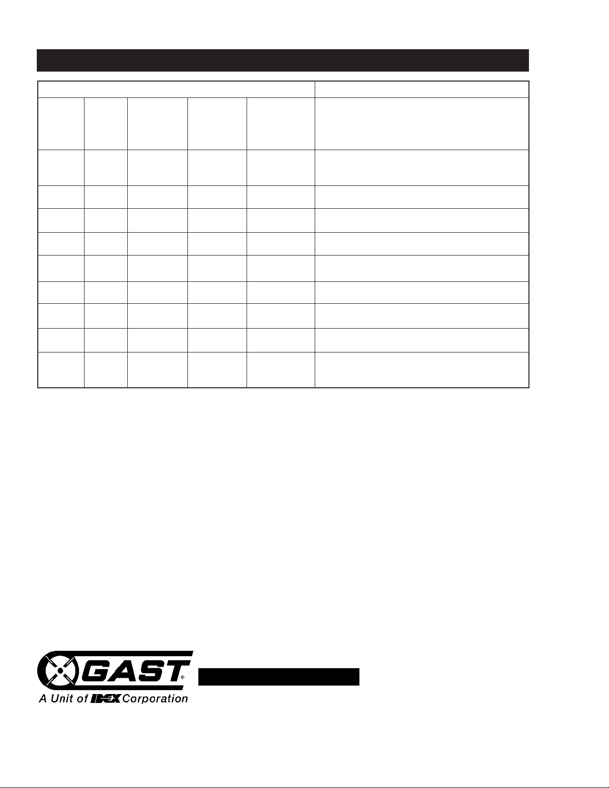
ROUBLESHOOTING CHART
T
Problem
Low Low Won’t Run Runs Hot Runs Well Reason & Remedy
Torque Speed Then Slows For Problem.
Down
•• • Dirt or foreign material present.
Inspect and clean.
•• • Internal rust. Inspect and clean.
•• • • •Vanes misaligned. Realign vanes.
•• Low air pressure. Increase pressure.
• Air line too small. Install larger line(s).
••Restricted exhaust. Inspect and repair.
•• • •Motor is jammed. Disassemble and repair.
••Air source inadequate. Inspect and repair.
••Air source too far from motor.
Reconfigure setup.
For the name of the nearest authorized service facility, contact one of our offices below or visit our website
at www.gastmfg.com.
European Sales & Service
Gast Manufacturing, Inc.
2300 S. Highway M139
Benton Harbor, MI 49022
Ph: 269/926-6171
FAX: 269/925-8288
www.gastmfg.com
Gast Hong Kong
Room 6, 9.,
New Commerce Centre
19 On sum St. Shatin
N. T. Hong Kong
Ph: (852) 2690 1008
Fax: (852) 2690 1012
www.gasthk.com
Headquarters
Gast Group Limited
A Unit of IDEX Corporation
Unit 11, The I O Centre
Nash Road
Redditch B98 7AS
United Kingdom
Tel: +44 (0) 1527 504040
Fax: +44 (0) 1527 525262
www.gastmfg.com
www.jun-air.com
12
 Loading...