

Page 1
70-2500 G446BPL (Rev. C)
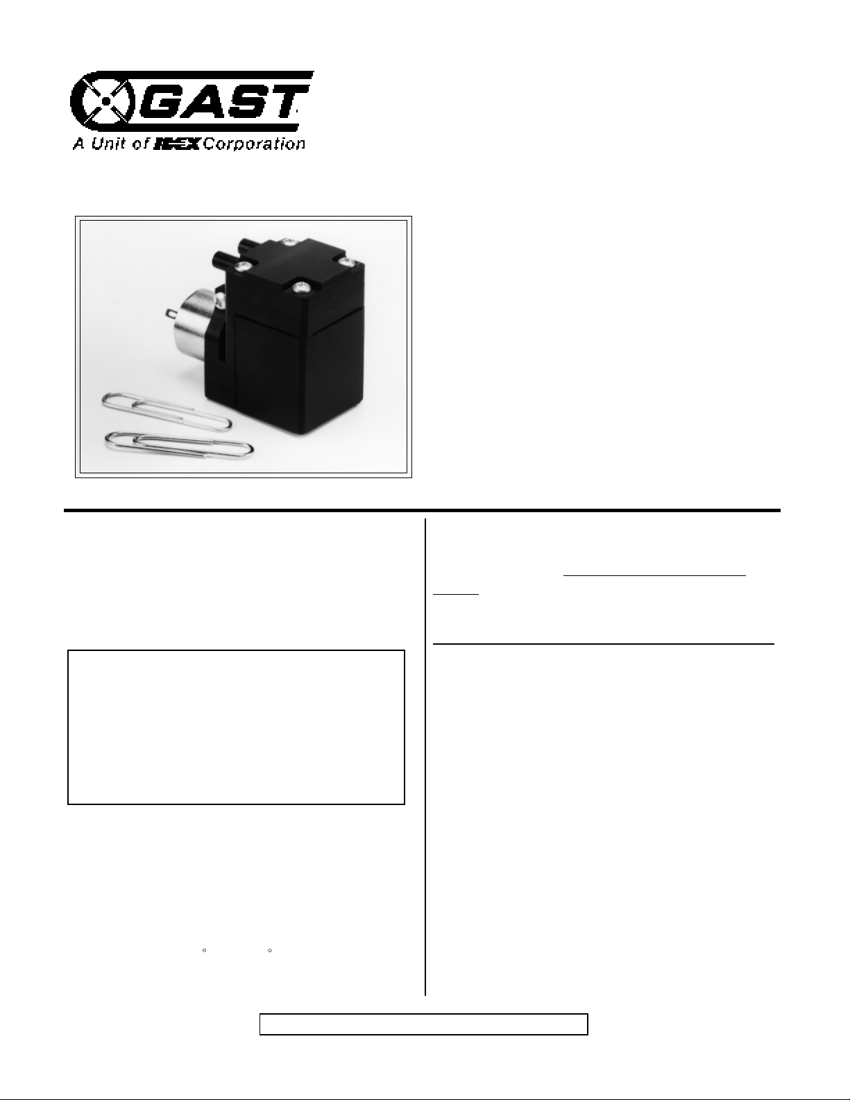
5D SERIES MINIATURE PUMP
OPERATION and MAINTENANCE
INSTRUCTION MANUAL
Contents:
General Information, Installation...........1
Operation, Wiring, and
Maintenance Inspection........................2
Exploded View and Parts Ordering
Information............................................3
Troubleshooting, and
Service Facilities...................................4
This is the hazard alert symbol: m When you see
this symbol be aware that personal injury or
property damage is possible. The hazard is
explained in the text following the symbol.
Read the information carefully before proceeding.
The following is an explaination of the three dif-
ferent types of hazards:
mDANGER Severe personal injury or death
will occur if hazard is ignored.
mWARNING Severe personal injury or death
can occur if hazard is ignored.
mCAUTION Minor injury or property damage
can occur if hazard is ignored.
GENERAL INFORMATION
mDANGER To prevent explosive hazard, do not
pump combustible liquids or
gases, or operate the pump in an
atmosphere containing them. Use
only in a well ventilated area.
m CAUTION Required ambient temperature is
-10 F to 150 F. For operation at
temperatures outside this range,
consult the factory.
Performance is reduced by lower atmospheric
pressure at high altitudes. Consult a Gast distributor for details. Never lubricate this oil-less
pump. The sealed bearings are grease-packed.
The service life of the diaphragm and valve will be
reduced by petroleum or hydrocarbon products.
INSTALLATION
mWARNING Beware of any exposed movable
parts. Proper guards should be in
place to prevent severe personal
injury.
mCAUTION Do not block the flow of cooling air
over the pump in any way.
MOUNTING
To reduce noise and vibration use shock mounts
or a vibration-isolated mounting surface. Do not
block the flow of cooling air over the unit in any
way.
PLUMBING
To prevent air flow restriction, use pipes and
fittings of the same size or larger than the barbed
ports. Note that the ports are not designed to
support plumbing.
KEEP THIS DOCUMENT FOR FUTURE REFERENCE
Page 2

RELIEF VALVES AND GAUGES
Install gauges in the lines to monitor performance. A relief valve can be installed at the
inlet or outlet, or both. Consult a Gast representative for performance limitations.
FILTERS
If operated in a dirt contaminated atmosphere, a
suitable filter should be used to ensure long
service.
mWARNING Before attempting repair, determine
if the pump has been exposed to/or
contains biological, toxic, or radio
active materials, so that the repair
personnel are not exposed to these
items.
Follow these steps to replace the diaphragm:
-Disconnect pump from electrical power.
WIRING
mWARNING Poor wiring can result in electric
shock. Wiring must conform to all
required safety codes and be
installed by a qualified person.
Refer to wiring diagram on next
page.
Check that the supply voltage agrees with the
pump label voltage. If the motor fails to start or
slows down under load, shut the unit off and
unplug it. If the pump is extremely cold, let it
warm up to a minimum of -10 F before starting.
OPERATION
mCAUTION The unit is designed to pump gases
only. Do not allow foreign mater ial
such as dirt or metal particles to
enter the unit. Water vapor, oil
based contaminants, or other
liquids should be filtered out.
mWARNING Always disconnect power source
before servicing. Failure to do so
can result in personal injury and/or
property damage.
-Vent all air lines to the pump to remove pressure.
mWARNING You must vent all air lines to the
pump to remove pressure before
you service it. Failure to do so can
result in personal and/or property
damage.
-Note the direction of the arrows so you can orient
the pump head correctly during reinstallation.
-Remove the four corner head screws and remove
the head, valve, and valve plate.
-Remove countersunk torque screw on retainer.
-Remove the retainer and diaphragm.
All electric motors generate heat. To avoid serious burns, never touch unit during or immediately
after operation. Always disconnect power source
before servicing. Do not block the flow of cooling
air over the motor in any way. Keep the air flow
vents free of foreign objects, dirt, lint etc.
MAINTENANCE
Do not attempt to replace the connecting rod or
motor bearings. If after cleaning the unit and/or
installing a new diaphragm or valve, the unit still
does not operate properly, contact you representative, the factory, or return the pump to one of our
Authorized Service Facilities.
-Clean the pump head and retainer using waterbased solvents.
mCAUTION Do not use petroleum-base com-
pounds, acids, caustics, or chlorinated solvents to clean or lubricate
any parts. It will reduce the service
life of the pump.
-Reattach retainer plate and diaphragm to rod with
flat head screw. Torque to 8 to 10 in-oz.
-Seat the diaphragm in the body so that the
outside edge of the diaphragm is centered into
the diaphragm pocket.
2
Page 3
MAINTENANCE conti.
-Place the valve in the valve plate pocket so that
the holes in the valve fit over the correct pins in
the valve plate.
-Place the entire head, valve, and valve plate
assembly on top of the bracket, by aligning the
four holes and orienting the ports in your desired
position.
-Assemble the head by fitting the correct holes in
the head onto the pins in the valve plate.
DC WIRING
RED/WHITE (+)
+
M
BLACK
-Torque the head screws to 26 to 30 in- oz. into
the body.
mCAUTION Do not over-tighten head screw(s).
To do so can risk stripping the
plastic threads.
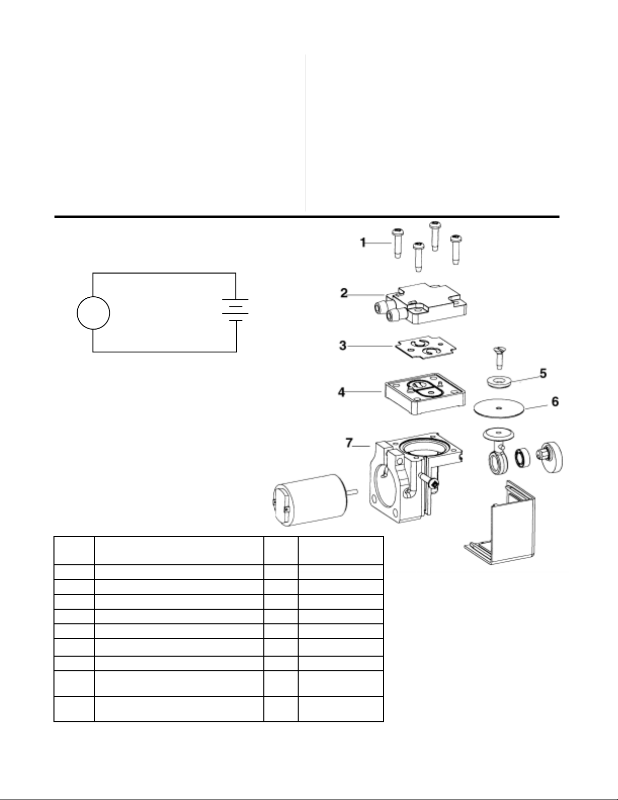
PARTS ORDERING INFORMATION
Ref.
No.
Description Part
Qty
5D
1 Head screws 4 SCR1019
2 Head 1 HDC1006
♦
3 *Valve 1 VLV1006
4 Valve Plate 1 VPL1005
5 Retainer 1 RPL1005
♦6
*Diaphragm 1 DPH1007
7 Body 1 BKT1008
Service Kit
Diaphragm Mat’l)
Service Kit
Diaphragm mat’l)
♦Denotes parts included in the service kit.
When corresponding or ordering parts, please give complete model and serial numbers.
*Material: Fluorocarbon, or EPDM.
(w/ Flourocarbon
( w/ EPDM
1 K789
1 K788
3
Page 4

TROUBLESHOOTING GUIDE
SYMPTOM POSSIBLE CAUSE POINT TO CHECK REMEDY
•Electrical Connection
Won’t Start
Excessive Noise •Wrong Voltage
Overheat ing •Dirty filter
Low Pressure/Low
Vacuum
•Dirty Muffler
•Wrong/Low Voltage
•Pressure/Vacuum on
Head
•Hose or plumbing leak
•Check Valve leaks
•Dirty mu ffler
•Low voltage
•Dirty valves
•Dirty filter
•Dirty mu ffler
•Low Voltage
•Wrong AC Voltage
Frequency
•Dam aged/Contami nated
diaphragm
•Dirty Valves
•Ensure elec trical power is
supplied
•Is muffler clogged
•Inspect power supply
•Inspect reli ef valve
•Inspect above points
•Inspect power supply
•Inspect hoses for cracks
•Inspect che ck valve
•Inspect filter
•Is muffler clogged
•Inspect power supply
•Remove head and inspect valve
•Inspect filter
•Inspect muffler
•Inspect power supply
•Inspect power supply
•Remove head & valve plate and
inspect diaphragm
•Remove head & inspect valve
•Check plug or wire
connection
•Replace muffler
•Apply proper voltage
•Reset or replace relief
valve
•Replace unit
•Apply proper voltage
•Replace hose
•Repair or replace chec k
valve
•Replace filter
•Replace muffler
•Apply proper voltage
•Clean/replace valve
•Replace filter
•Replace muffler
•Supply proper electr ical
power
•Supply proper electr ical
power
•Replace diaphragm
•Clean/Replace valve
AUTHORIZED SERVICE FACILITIES
Gast Manufacturing Inc. Gast Manufacturing Inc. Brenner Fiedler & Assoc. Gast Manufacturing Co., Ltd
2300 Highway M-139 505 Washington A ve 13824 Bentley Place Beech House, Knaves Beech
Benton Harbor, MI 49023 Carlstadt, NJ 07072 Cerritos, CA 90701 Business Centre, Loudw ater
TEL: 616-926-6171 TEL: 201-933-8484 TEL: 800-843-5558 High Wycombe, Bucks HP 10 9SD
F AX: 616-927-0808 F AX: 201-933-5545 TEL: 310-404-2721 England
F AX: 310-404-7975 TEL: 44 628 532600
F AX: 44 628 532470
Wainbee Limited Wainbee Limited Japan Machinery Co. Ltd. NOT E: General Correspondence
215 Brunswick Blvd. 5789 Coopers Aven ue Central PO Box 1451 should be sent to—
Pointe Claire, Quebec Mississauga, Ontario T okyo, 100-91 Japan Gast Mfg. Inc./A Unit of IDEX Corporation
Canada H9R 4R7 Canada L4Z 3S6 TEL: 81-3-3573-5421 P O Box 97
TEL: 514-697-8810 TEL: 905-568-1700 F AX: 81-3-3571-7865 Benton Harbor, MI 49023-0097
FAX: 514-697-3070 FAX: 905-568-0083 or: 81-3-3571-7896
4
 Loading...