

Page 1
www.gastmfg.com
ISO 9001 & 14001 CERTIFIED
®Registered Trademark/™Trademark of Gast Manufacturing Inc., Copyright © 2002 Gast Manufacturing Inc. All Rights Reserved.
PART NO. 70 - 6201 (REV-A)
WARNING
PLEASE READ THIS MANUAL COMPLETELY BEFORE INSTALLING AND USING
THIS PRODUCT. SAVE THIS MANUAL FOR FUTURE REFERENCE AND
KEEP IN THE VICINITY OF THE PRODUCT.
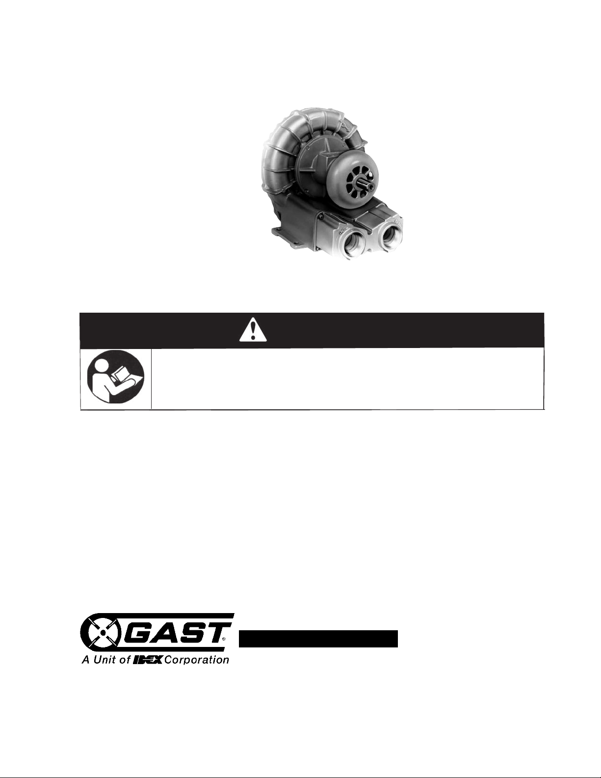
SEPARATE DRIVE REGENAIR BLOWER
OPERATION & MAINTENANCE MANUAL
Thank you for purchasing this Gast product. It is manufactured to the highest standards
using quality materials. Please follow all recommended maintenance, operational
and safety instructions and you will receive years of trouble free service.
Product Use Criteria:
• Operate at -20ºF - 104ºF (-29ºC - 40ºC).
• Protect unit from dirt & moisture.
• Protect all surrounding items from exhaust air. This
exhaust air can become very hot.
• Corrosive gases and particulate material may
damage unit. Water vapor, oil-based contaminants
or other liquids must be filtered out.
• The blower must be installed with the properly sized inlet and inline filters, gauges and
relief valves to protect the product from dirt and over-heating.
• Consult your Gast Distributor/Representative
before using at high altitudes.
Page 2
our safety and the safety of others
Y
is extremely important.
Check rotation before connecting to plumbing. Inlet and
utlet ports are not designed to support plumbing.
o
We have provided many important safety messages
in this manual and on your product. Always read
and obey all safety messages.
This is the safety alert symbol. This symbol
alerts you to hazards that can kill or hurt you and
others. The safety alert symbol and the words
“DANGER” and “WARNING” will precede all safety
messages. These words mean:
DANGER
You will
follow instructions.
be killed or seriously injured if you don’t
WARNING
You can
follow instructions.
All safety messages will identify the hazard, tell you
how to reduce the chance of injury, and tell you
what can happen if the safety instructions are not
followed.
INSTALLATION
Correct installation is your responsibility. Make sure
you have the proper installation conditions and that
installation clearances do not block air flow.
Blocking air flow over the product in any way can
cause the product to overheat.
The blower must be installed with the properly sized
inlet filter, gauge and relief valve to protect the
product from dirt and over-heating.
be killed or seriously injured if you don’t
Remove plugs from the IN and OUT ports. Use a small
amount of pipe thread lubricant when connecting
plumbing to protect the aluminum blower threads.
Connect with pipe and fittings that are the same size or
larger than the productʼs threaded ports. When
installing two blowers in parallel, use plumbing that is
two whole pipe sizes larger in diameter than that of the
blower. Be sure to connect the intake and exhaust
plumbing to the correct inlet and outlet ports.
lumbing to remove the hot discharge air of large
P
Accessories
Install two vacuum gauges, one before and one after
filter, to monitor restriction through filters. As filters
become clogged, performance efficiency will be
reduced. Filters should be checked periodically and
replaced when necessary. See pages 6, 7 and 8 for
installation.
Install a relief valve to avoid changes in pressure or
vacuum that can cause overloading of large blowers.
Install an intake filter with a relief valve to prevent
foreign material from entering blower if blower is used in
a vacuum application in a dirty environment. In
applications where there is high humidity or liquids
being used in the process, install a moisture separator.
See Recommended Accessories on pages 7-9 or
consult your Gast Distributor/Representative for
additional filter and accessories recommendations. Do
Not install check valves that close with a strong spring.
The recommended check valves (page 7) provide
minimal pressure drop, positive sealing and are
resistant to the high discharge temperatures of large
blowers.
Electrical Connection
Mounting
The single impeller blower should be oriented with the
shaft in a horizontal position, unless the modelʼs product
features state otherwise. Mounting the product to a
stable, rigid operating surface and using shock mounts will
reduce noise and vibration. Make sure that appropriate
noise dampening media is used with respect to the
working media for the application.
Rotation
From the drive side of the blower, check that the blower is
rotating clockwise. (he drive side is marked with an arrow
on most models.) Proper rotation can also be checked by
the air flow at the IN and OUT ports.
Plumbing
Remove any foreign material (burrs, chips, welding
drops, slag, pipe cuttings, excess sealant, sand or
lime)
Check rotation before connecting to plumbing. Inlet
and outlet ports are not designed to support plumbing.
WARNING
If working media other than standard atmosphere
is to be pumped through unit, consult factory for
acceptable parameters. Severe personal injury may
occur if hazard is ignored.
CAUTION:
Never lubricate this oil-less blower. The sealed
bearings are grease packed. All of the wetted
components are made with corrosion resistant
material and with paper filtration. The unit should
last for years.
Internal wetted components are either stainless
steel or coated for corrosion resistance. The blower
is sealed with a shaft seal and impregnated castings
to prevent working fluid leakage during operation.
2
Page 3
OPERATION
Injury Hazard
Install proper safety guards as needed to prevent
a
ny close contact with blower suction area.
Keep fingers and objects away from openings and
rotating parts.
Product surfaces become very hot during operation,
allow product surfaces to cool before handling.
Air stream from product may contain solid or liquid
m
aterial that can result in eye or skin damage,
wear proper eye protection.
Wear hearing protection. Sound level from some
models may exceed 85 dBA.
Failure to follow these instructions can result in
burns, eye injury or other serious injury.
WARNING
Electrical Shock Hazard
Disconnect electrical power supply cord to drive
motor before performing maintenance on this
product.
Some motors are thermally protected and will
automatically re-start when protector resets.
If product is hard wired into system, disconnect
electrical power at the circuit breaker or fuse box
before performing maintenance on this product.
Failure to follow these instructions can result in
death, fire or electrical shock.
c
WARNING
Injury Hazard
Product surfaces become very hot during operation,
allow product surfaces to cool before handling.
Air stream from product may contain solid or liquid
material that can result in eye or skin damage,
wear proper eye protection.
Failure to follow these instructions can result in
burns, eye injury or other serious injury.
WARNING
It is your responsibility to operate this product at
recommended pressures or vacuum duties and
room ambient temperatures.. Do not throttle
discharge or suction pipe to reducer capacity.
Throttle will increase differential pressure causing
increasing power absorption and working
temperatures.
Start Up
Operate blower for an hour and then check:
1. Ambient temperature – Check room and
discharge air temperatures. Increased room
temperatures may require stronger ventilation
especially for larger blowers. Exhaust air
should not exceed 215ºF (102ºC) for all
blowers less than 3.5 Hp. Exhaust air should
not exceed 275ºF (135ºC) for all blowers
above 3.5 Hp.
2. Working pressure and vacuum values – Adjust
relief valve pressure or vacuum setting, if
needed.
WARNING
Power must be de-energized and disconnected
from the drive motor before servicing. Be sure all
rotating parts have stopped, electrical shock or
severe cuts can result if hazard is ignored.
It is your responsibility to regularly inspect and
make necessary repairs to this product in order to
maintain proper operation. Make sure that pressure
and vacuum is released from product before
starting maintenance.
The separate drive electric motor and blower need
periodic cleaning to remove accumulated dust and dirt.
If they are not cleaned, this can result in excessive
vibration, an increase in temperature or can reduce the
service life of the system.
MAINTENANCE
Check filter elements and clean motor and blower after
first 500 hours of operation. Replace filter elements.
This one procedure will help assure the productʼs
performance and service life.
An increase in the differential pressure across an inlet
filter indicates its getting clogged. Clean the inlet air
filter as often as needed, blowing down against the
current to clean it. A dirty filter cartridge causes a high
intake resistance resulting in an increase of differential
pressure, absorbed power and working temperature.
Failure to clean replace these filters will result in
excessive pressure drop, a reduction in system air flow
and the blower will run hotter.
3
Page 4
Belt Tensioning and Alignment
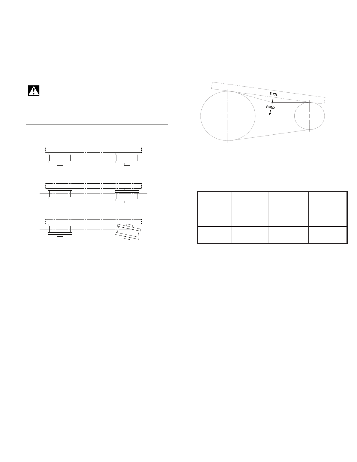
PROPER ALIGNMENT WITH STRAIGHT EDGE TOOL
T
OOL
PARALLEL MISALIGNMENT
TOOL
ANGULAR MISALIGNMENT
TOOL
DRIVE ALIGNMENT
FIGURE 1
C
L
C
L
C
L
D
EFLECTION 1/4 INCH
FIGURE 2
Fig. 1 shows how a straight edge tool should be used to
avoid parallel or angular misalignment. Table 1 shows the
orce needed on the electric motor shaft to properly
f
tension the belt drive when the belt is installed. This table
also shows the small force needed to cause 1/4” of
deflection in the belt, see Fig 2. This is used to check belt
tension in new drives or those in service.
CAUTION:
Do not over tighten belt as it will cause
misalignment and could lead to premature failure.
Gates “Poly Chain” Belt Tensioning Requirements
Belt Tensioning and Alignment (cont.)
We strongly suggest using a Gates Poly Chain Drive. It
has been properly engineered for this type of application.
If you choose to use a “V” belt drive, the sheave on the
blower must be less than 4” in outside diameter. This
sheave should be mounted on the shaft such that it will
not block air from entering the blower cooling fan (we
recommend this high speed belt drive be engineered
following the belt drive manufacturers recommendations).
To avoid annoying vibration and noise, both sheaves
should be dynamically balanced and fit snugly on the
shaft.
Gast Blower Required pull Force to deflect Gates Poly
on motor shaft belt 1/4” with Chain Belt
for correct new belt drive/ Part#
installation Low limit for
broken in drive
SDR4 66 lbs. 3.5/2.8 lbs 8M-1000-12
4
Page 5

WARRANTY
Gast finished products, when properly installed and operated under normal conditions of use, are warranted by Gast to be free
from defects in material and workmanship for a period of twelve (12) months from the date of purchase from Gast or an
authorized Gast Representative or Distributor. In order to obtain performance under this warranty, the buyer must promptly (in no
e
vent later than thirty (30) days after discovery of the defect) give written notice of the defect to Gast Manufacturing
Incorporated, PO Box 97, Benton Harbor Michigan USA 49023-0097 or an authorized Service Center (unless specifically agreed
upon in writing signed by both parties or specified in writing as part of a Gast OEM Quotation). Buyer is responsible for freight
charges both to and from Gast in all cases.
This warranty does not apply to electric motors, electrical controls, and gasoline engines not supplied by Gast. Gastʼs warranties
also do not extend to any goods or parts which have been subjected to misuse, lack of maintenance, neglect, damage by
accident or transit damage.
T
HIS EXPRESS WARRANTY EXCLUDES ALL OTHER WARRANTIES OR REPRESENTATIONS EXPRESSED OR IMPLIED
BY ANY LITERATURE, DATA, OR PERSON. GASTʼS MAXIMUM LIABILITY UNDER THIS EXCLUSIVE REMEDY SHALL
NEVER EXCEED THE COST OF THE SUBJECT PRODUCT AND GAST RESERVES THE RIGHT, AT ITS SOLE DISCRETION,
TO REFUND THE PURCHASE PRICE IN LIEU OF REPAIR OR REPLACEMENT.
GAST WILL NOT BE RESPONSIBLE OR LIABLE FOR INDIRECT OR CONSEQUENTIAL DAMAGES OF ANY KIND, however
arising, including but not limited to those for use of any products, loss of time, inconvenience, lost profit, labor charges, or other
incidental or consequential damages with respect to persons, business, or property, whether as a result of breach of warranty,
negligence or otherwise. Notwithstanding any other provision of this warranty, BUYERʼS REMEDY AGAINST GAST FOR
GOODS SUPPLIED OR FOR NON-DELIVERED GOODS OR FAILURE TO FURNISH GOODS, WHETHER OR NOT BASED
ON NEGLIGENCE, STRICT LIABILITY OR BREACH OF EXPRESS OR IMPLIED WARRANTY IS LIMITED SOLELY, AT
GASTʼS OPTION, TO REPLACEMENT OF OR CURE OF SUCH NONCONFORMING OR NON-DELIVERED GOODS OR
RETURN OF THE PURCHASE PRICE FOR SUCH GOODS AND IN NO EVENT SHALL EXCEED THE PRICE OR CHARGE
FOR SUCH GOODS. GAST EXPRESSLY DISCLAIMS ANY WARRANTY OF MERCHANTABILITY OR FITNESS FOR A
PARTICULAR USE OR PURPOSE WITH RESPECT TO THE GOODS SOLD. THERE ARE NO WARRANTIES WHICH
EXTEND BEYOND THE DESCRIPTIONS SET FORTH IN THIS WARRANTY, notwithstanding any knowledge of Gast regarding
the use or uses intended to be made of goods, proposed changes or additions to goods, or any assistance or suggestions that
may have been made by Gast personnel.
Unauthorized extensions of warranties by the customer shall remain the customerʼs responsibility.
CUSTOMER IS RESPONSIBLE FOR DETERMINING THE SUITABILITY OF GAST PRODUCTS FOR CUSTOMERʼS USE OR
RESALE, OR FOR INCORPORATING THEM INTO OBJECTS OR APPLICATIONS WHICH CUSTOMER DESIGNS,
ASSEMBLES, CONSTRUCTS OR MANUFACTURES.
This warranty can be modified only by authorized Gast personnel by signing a specific, written description of any modifications.
5
Page 6
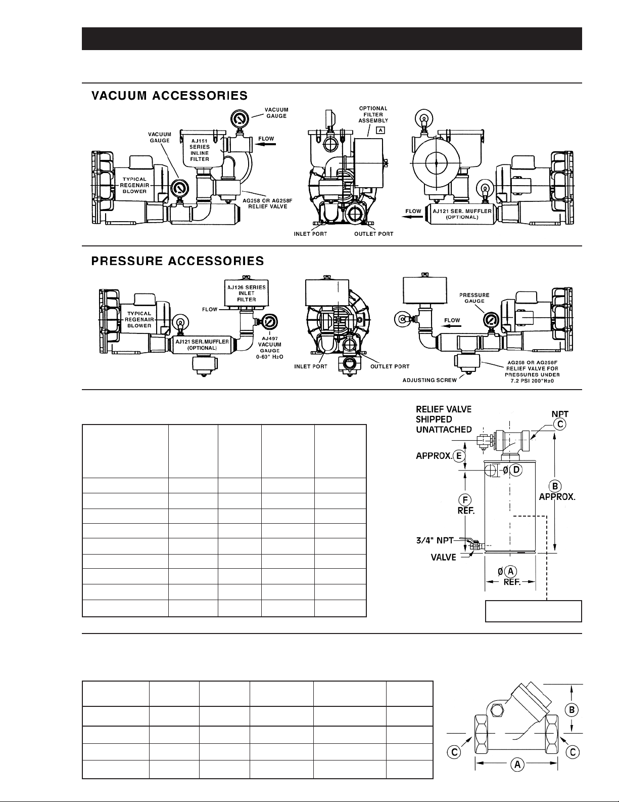
RECOMMENDED ACCESSORIES
he following diagrams are only suggested configurations for these accessories. These accessory configurations may
T
vary depending upon a particular unitʼs application.
MOISTURE SEPARATOR (FOR VACUUM)
This moisture separator removes liquids from the gas stream in a vacuum process.
This helps protect the blower from corrosion and the build up of mineral deposits.
For Model Number R3, R4, R5 R4, R4H, R4H, R4M, R4M, R6,
R4P, R5 R5, R6, R6P, R6PP,
R6P, R6PS, R7, R7P,
R7S, R9,
R9S
Part Number RMS160 RMS200 RMS300 RMS400
CFM capacity 160 200 300 400
Liquid capacity (gal.) 10 19 19 40
Diameter (A) 14.8” 19.7” 19.7” 24”
Dimension (B) 37.5” 35” 35” 44”
NPT outlet (C) 2” 2” 2.5” 3”
Inlet diameter (D) 2” 2” 2.5” 3”
Dimension (E) 7.5” 7.5” 7.5” 9.7”
Dimension (F) 26.6” 26.6” 26.6” 29”
Maximum vacuum allowed: 22” Hg.
HORIZONTAL SWING TYPE CHECK VALVE
This check valve prevents backwash of fluids from entering the blower and air back-streaming.
The check valve can be mounted to discharge or inlet either vertically or horizontally. The check
valve will open with 3” of water pressure or vacuum.
Model Number R1, R2 R3 R4, R5, SDR4, R6, R6P, SDR6P, R7, R7S
SDR4, R4P SDR6, R6PS
Part Number AH326B AH326C AH326D AH326F AH326G
Dimension (A) 3.57” 4.19” 4.50” 5.25” 8.00”
Dimension (B) 2.32” 2.69” 2.94” 3.82” 5.07”
Dimension (C) 1.00” NPT 1.25” NPT 1.50” NPT 2.00” NPT 2.50” NPT
X
Explosion-proof, high level
float switch AJ213 (optional).
6
Page 7
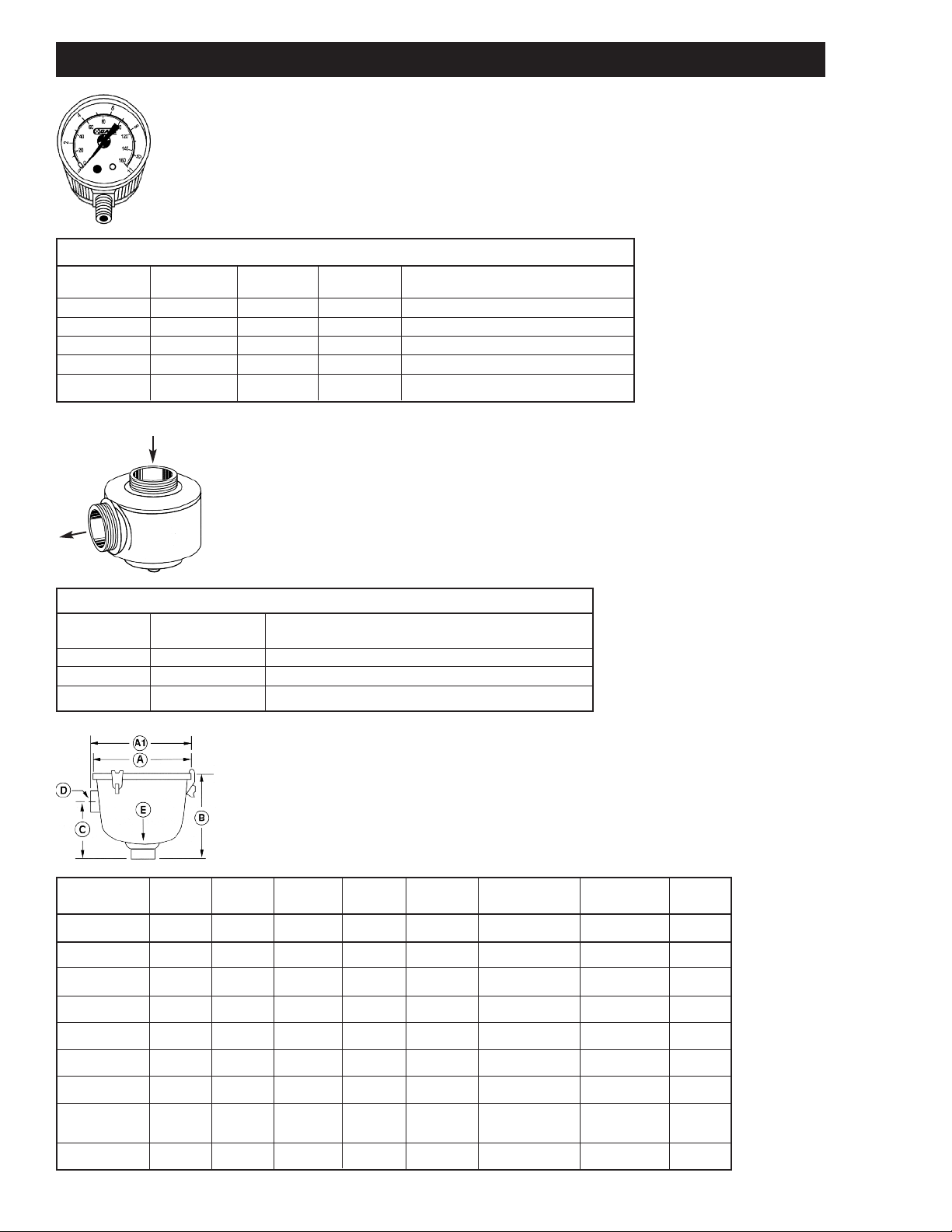
RECOMMENDED ACCESSORIES
PRESSURE – VACUUM GAUGE
Pressure/Vacuum Gauges
AJ496 2.50” Dia. Pressure 1/4” NPT 0-60 in. H2O and 0-150 mbar
AE133 2.50” Dia. Pressure 1/4” NPT 0-160 in. H2O and 0-400 mbar
AE133A 2.50” Dia. Pressure 1/4” NPT 0-200 in. H2O
AJ497 2.50” Dia. Vacuum 1/4” NPT 0-60 in. H2O and 0-150 mbar
AE134 2.50” Dia. Vacuum 1/4” NPT 0-160 in. H2O and 0-400 mbar
AE134F 3.50” Dia. Vacuum 1/4” NPT 0-15 in. HG
PRESSURE – VACUUM RELIEF VALVE
Pressure/Vacuum Relief Valves
AG258 1.50” NPT Adjustable 30-200 in. H2O; 200 cfm max
AJ121D Silencer for AG258 Relief Valve
AG258F 2.50” NPT Adjustable 25-200 in. H2O; 560 cfm max
AJ121G Silencer for AG258F Relief Valve
INLINE FILTERS (FOR VACUUM)
The impeller of a blower passes very closely to the housing. It is recommended
to have an inlet or in-line filter to ensure a trouble-free service life.
MPT = Male Pipe Thread
FPT = Female Pipe Thread
Model Number R1 R2 R3 R4 SDR4, R4P, SDR5, SDR6, R6, R6PP, SDR6P, R7S, R9,
Part Number AJ151A AJ151B AJ151C AJ151D AJ151E AJ151G AJ151H AJ151M
Dimension (A) 5.88” 7.38” 7.38” 7.38 8.75 8.75” 14.00” 18.50”
Dimension (A1) ––– – – – 16.25” 20.75”
Dimension (B) 4.50” 6.81” 6.81” 6.81” 10.25” 10.50” 27.13” 28.13”
Dimension (C) 2.75” 4.62” 4.62” 4.62” 5.00” 5.50” 18.50” 19.50”
Dimension (D) 1.00” FPT 1.00” FPT 1.25” FPT 1.50” FPT 2.00” FPT 2.50” FPT 3”MPT 5” MPT
Dimension (E) 1.00” FPT 1.00” FPT 1.25” FPT 1.50” FPT 2.00” FPT 2.50” FPT 3”MPT 5” MPT
Replacement AJ135D AJ135E AJ135E AJ135E AJ135F AJ135G AJ135C AJ135H
Element
Micron 10 10 10 10 10 10 10 10
R4H, R5 R6P, R7M R6PS, R7, R7S R9P, R9S
7
Page 8
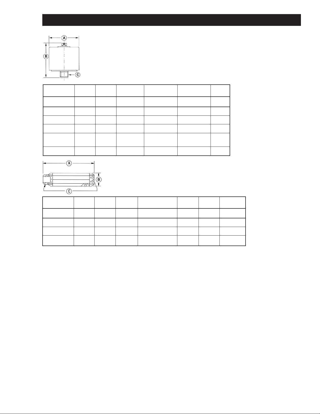
RECOMMENDED ACCESSORIES
INLET FILTERS (FOR PRESSURE)
ll filters are heavy duty for high-particulate service. Inlet filters for
A
Regenair blowers are drip-proof when mounted as shown..
MPT = Male Pipe Thread
PT = Female Pipe Thread
F
Model Number R1, R2 R3 R4, R4H, R4P SDR5, R6, SDR6, SDR6P, R7, R9, R9P,
art Number AJ126B AJ126C AJ126D AJ126F AJ126G AJ126M
P
Dimension (A) 6.00” 6.00” 7.70” 10.62” 10.00” 16.00”
imension (B) 4.62” 7.12” 7.12” 4.81” 13.12” 14.62”
D
Dimension (C) 1.00” MPT 1.25” MPT 1.50” MPT 2.00” FPT 2.50” MPT 5” MPT
eplacement AJ134B AJ134C AJ134E AG340 AJ135A AJ135H
R
Element
Micron 10 10 10 10 10 10
SDR4, R5 R5P, R6PP, R6PS R7P, R7S R9S
MUFFLERS
Designed to reduce noise by up to 5 dbA and remove
high-frequency sound associated with all blowers.
*Used only on applications with clean dry air working media
Model Number R1, R2 R3 R4, SDR4, R4H, R6, R6P, R6PS R7, R7S R6PP, R9 R7P
Part Number AJ121B AJ121C AJ121D AJ121F AJ121G AJ121H AJ121M
Dimension (A) 7.46” 7.94” 12.75” 17.05” 17.44” 20.30” 33.60”
Dimension (B) 2.38” 2.62” 3.25” 3.63” 4.25” 4.75” 6.00”
Dimension (C) 1.00” NPT 1.25” NPT 1.50” NPT 2.00” NPT 2.50” NPT 3” NPT 4”NPT
R4P, R5 SDR6P, SDR6 Exhaust Exhaust
8
Page 9
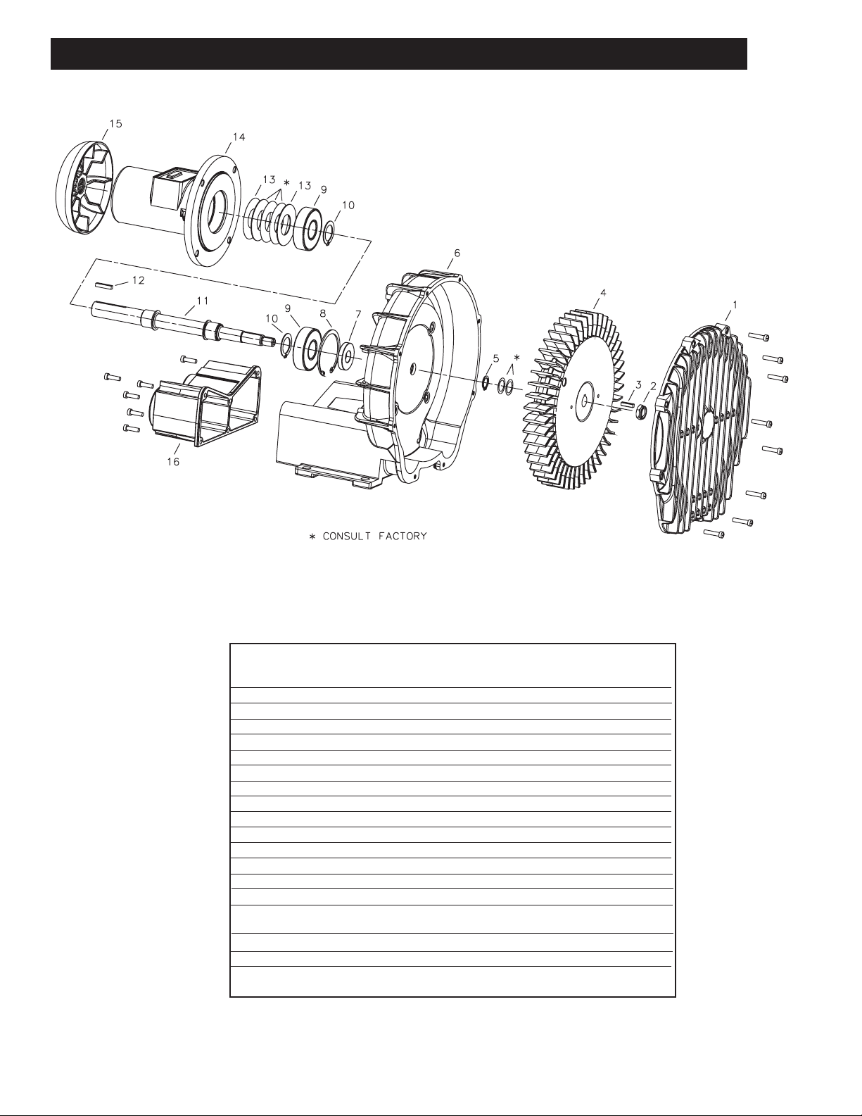
PARTS & ORDERING INFORMATION
REF# ITEM QTY Part#
1 COVER 1 AJ101DJ
2 LOCK NUT 1 BC181DJ
3 SS KEY 1 AB136AB
4 IMPELLER 1 AJ102DJ
* SHIM SPACERS * AJ109
5 RETAINING RING 1 AJ149A
6 HOUSING 1 AJ103DJ
7 SHAFT SEAL 1 AK271
8 BIG RETAINING RING 1 AB793
9 BEARING 2 AB964DJ
10 RETAINING RING 2 AG900
11 SHAFT 1 AJ157DJ
12 KEY 1 AB136D
13 BEARING SPRING 2 AB791
* WASHER * AB792
AB792DJ
14 REMOTE DRIVE HOUSING 1 AJ153DJ
15 FAN 1 AD235D
16 MUFFLER EXTENSION 1 AJ106DJ
9
Page 10
PART NO. 70 - 6201 (REV-A)
www.gastmfg.com
ISO 9001 & 14001 CERTIFIED
ROUBLESHOOTIN G CHART
T
Problem Reason Remedy
Unusual belt noise -Misaligned drive -Correct alignment
-Too high or low belt tension -Adjust tention to correct value
Loss of belt tension -Blower or motor not bolted down -Check for loose bolts, then realign
tightly realign and tension
-Debris being pinched in between -Keep Gast supplied belt guard
between belt & sprocket in place
Excessive wear to edge of belt -misaligned drive -Correct alignment
Premature wear or shearing -Too high or low belt tension -Adjust tension to correct value
of belt check to teeth
-Blower jammed -Check the blower, will it turn easily
Broken Belt -Debris being pinched in between -Keep Gast supplied belt guard
belt and sprocket in place
Excessive vibration -Loose sprocket or key -Tighten and/or Loctite to prevent
movement
-Impeller damaged by foreign material -Replace impeller
-Impeller contaminated by foreign -Clean impeller, install adequate
material filtration
Abnormal Sound -Impeller is damaged or contaminated -Replace or clean impeller
by foreign material -Install adequate filtration
Blown Fuse -Electrical wiring problem -Have qualified person check that
impeller turns
-Check fuse, wiring diagram or wiring
capacity
Unit very hot -Running at too high a pressure -Install a relief valve and
or vacuum pressure or vacuum gauge
Clean or replace impeller. Install
proper filtration
We have Gast Certified Service Centers throughout the world. For the most up-todate listing, contact one of our sales offices below:
World Headquarters
P.O. Box 97
2300 S. Highway M139
Benton Harbor, MI 49022
Ph: 269/926-6171
FAX: 269/925-8288
www.gastmfg.com
European Sales & Service Headquarters
Gast Group Limited
A Unit of IDEX Corporation
Unit 11, The I O Centre
Nach Road
Redditch B98 7AS
United Kingdom
Tel: +44 (0) 1527 504040
Fax: +44 (0) 1527 525262
www.gastmfg.com
www.jun-air.com
Gast Hong Kong
Unit 12, 21/F, Block B
New Trade Plaza
6, On Ping Street, Shatin
N. T. Hong Kong
Ph: (852) 2690 1008
Fax: (852) 2690 1012
www.gasthk.com
 Loading...