

Garmin GPSMAP 545s w/o Xdcr, GPSMap 540s No Xdcr, GPSMAP 535s, GPSMAP 530s, GPSMAP 526 Installing
...
Installing the Flush Mount Kit
Use this kit to ush mount a GPSMAP 500 series unit into a at panel.
Select an appropriately sized location for the unit.
•
Use the Flush Mount Template provided to determine a location.
•
Check that all cables reach the unit mounting location.
•
Always wear safety goggles and a dust mask when drilling, cutting, or sanding.
•
Included mounting hardware—(1) unit housing, (1) rubber seal, (2) tension mount brackets, (4) hex bolts, (4) hex nuts, and (4) wing nuts.
Tools (not included)—drill, 3/
" (10 mm) drill bit, jig saw, and a
8
To install the Flush Mount Kit:
1. Cut the opening:
The ush mount template has adhesive on the back. Remove the protective liner and apply the template to the location you want to
•
mount the unit.
Using a 3/8" (10 mm) drill bit, drill the pilot holes indicated on the template to begin cutting the mounting surface.
•
Using the jig saw, cut the mounting surface along the inside of the line indicated on the template. Be very careful when cutting this
•
hole, because there is only a small amount of clearance between the unit housing and the tension mount arms. Cut slightly inside the
indicated line and then sand or le the panel as needed to obtain the best t.
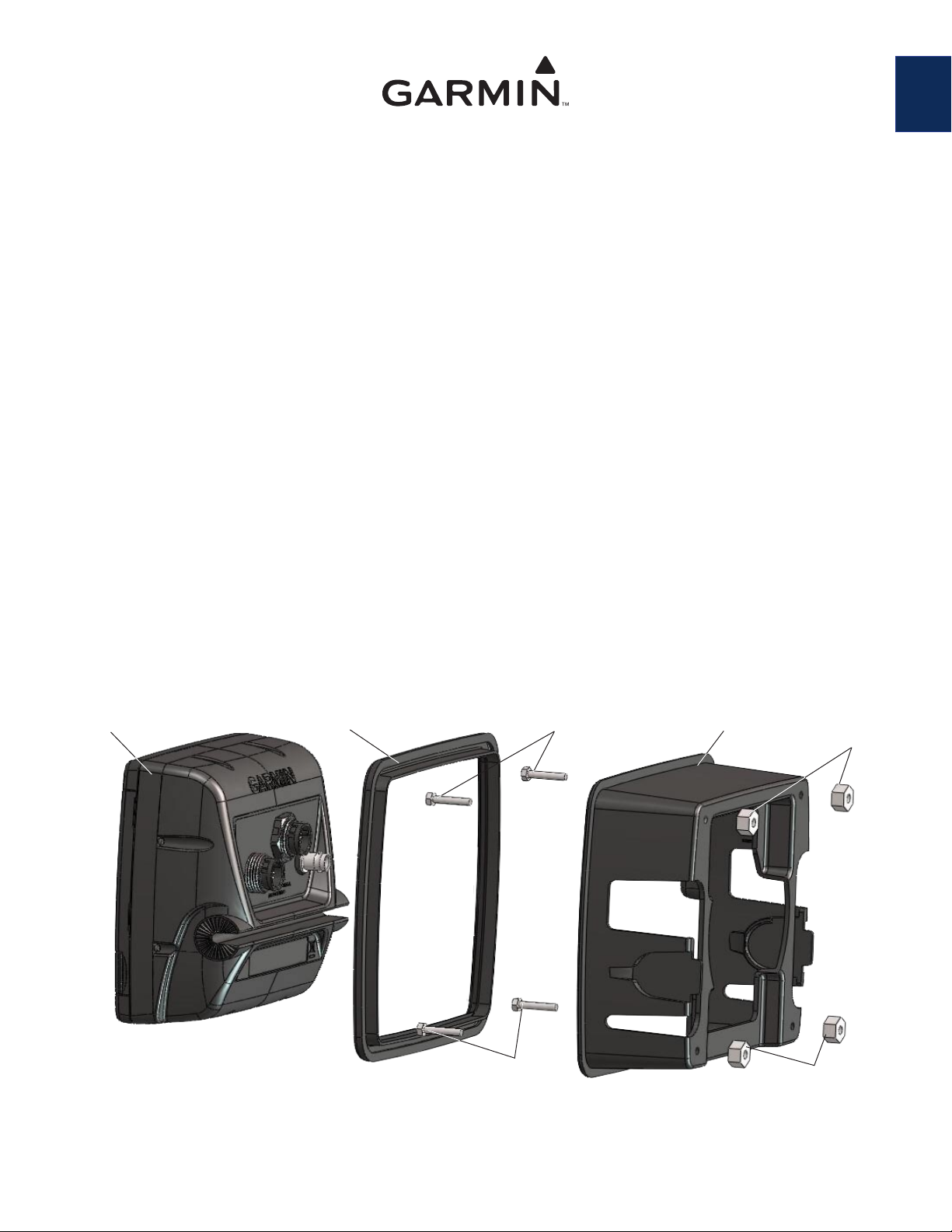
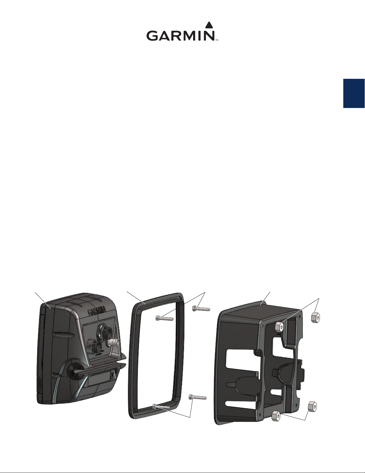
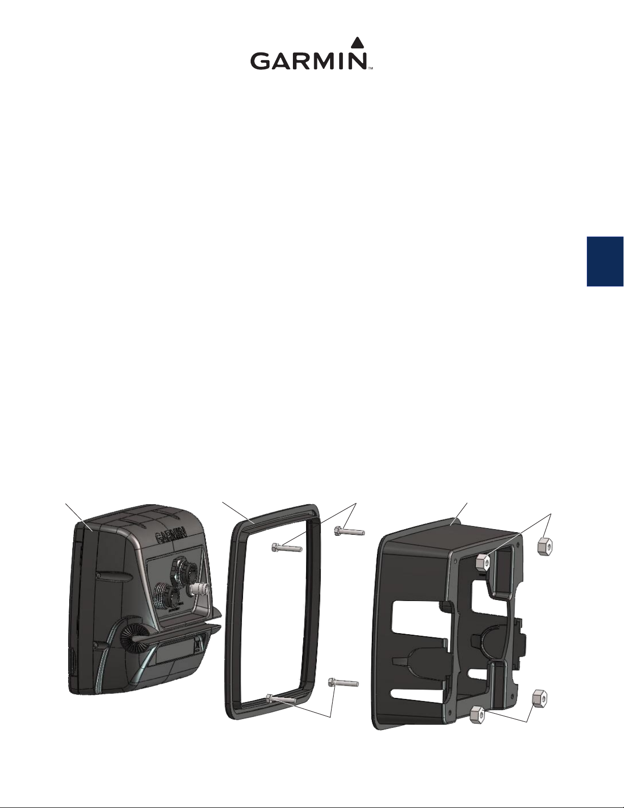
2. Assemble the ush mount hardware (see Figure 1):
Attach the rubber seal to the front of the unit housing.
•
Insert the four hex bolts into the unit housing so they stick out of the back.
•
Use the four hex nuts to secure the hex bolts to the unit housing. Using the
•
overtightening.
Slide the unit into the unit housing. (If you have limited space behind the mounting surface, this can be done in step 3.)
•
When the unit is inserted correctly, it will snap into place within the unit housing.
•
Connect the wiring harness, GPS antenna, and XM antenna (if applicable) to the unit. (This can also be done in step 3, if necessary.)
•
9
/
" (7 mm) wrench.
32
9
/32" (7 mm) wrench, tighten the nuts without
EN
Unit
October 2007 Part Number 190-00553-01 Rev. B Printed in Taiwan
Rubber seal
Hex bolts
Hex bolts
Figure 1
Unit housing
Hex nuts
Hex nuts
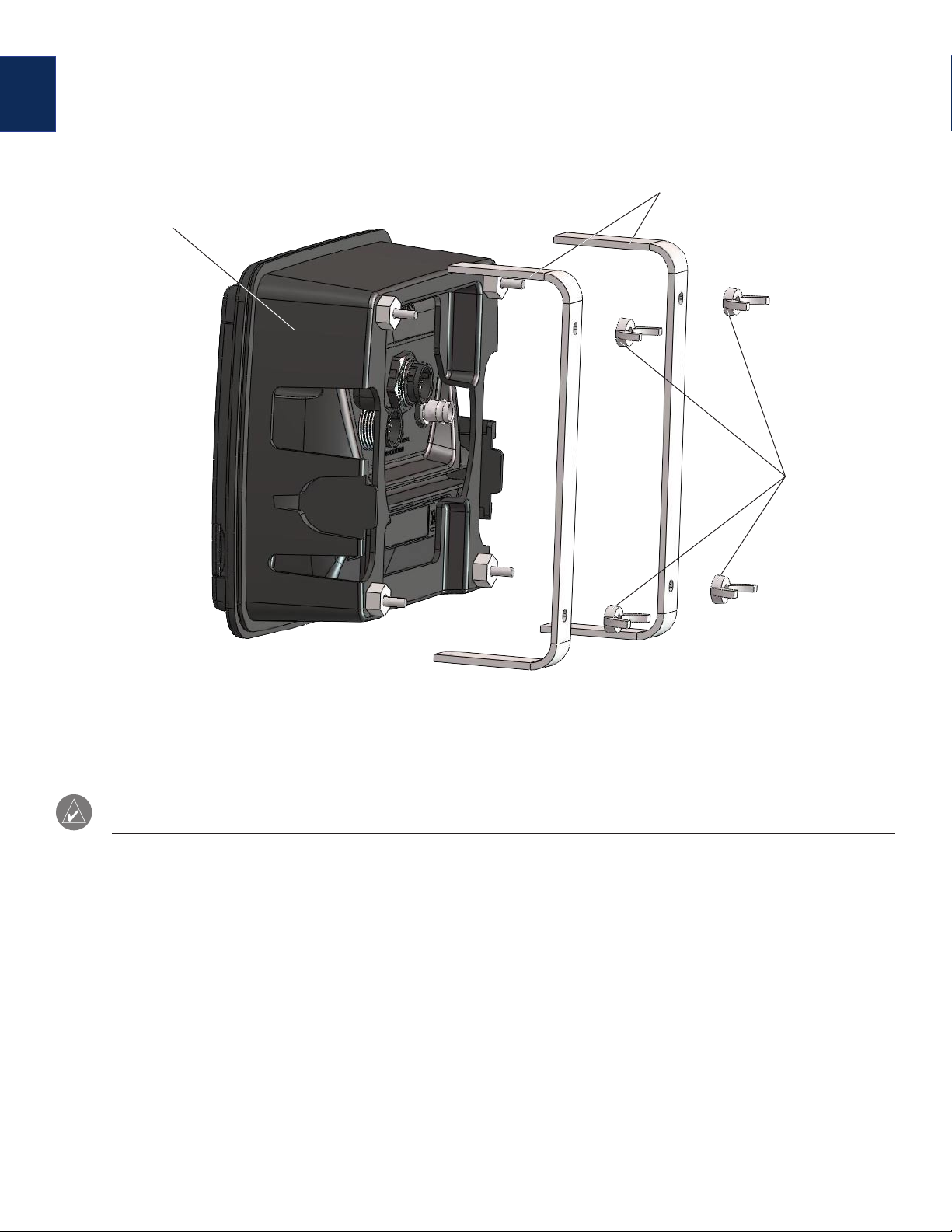
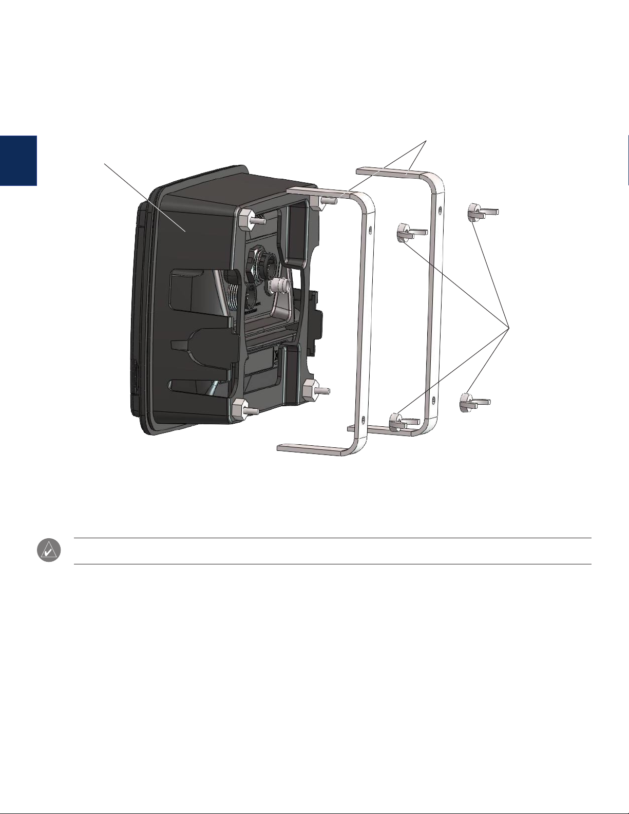
3. Install the unit in the opening (see Figure 2):
EN
Place the unit housing in the recently cut hole in the mounting surface.
•
Slide the tension mount brackets onto the hex bolts and secure them with the four wing nuts.
•
Tighten the four wing nuts to secure the unit housing to the mounting surface. Be careful not to overtighten.
•
If you did not do so in step 2, connect the wiring harness to the unit, then slide the unit into the unit housing until it snaps in place.
•
Assembled unit and
ush mount hardware
Tension mount brackets
Wing nuts
Figure 2
NOTE: You must connect the wiring harness to the boat’s power supply, GPS antenna, XM antenna (if applicable), and transducer (if applicable)
per the installation instructions included with the unit.
Installation du kit de montage sur panneau
Utilisez ce kit pour monter un appareil de la série GPSMAP 500 sur un panneau plat.
Sélectionnez un emplacement de taille adéquate pour monter l'appareil.
•
Utilisez le modèle de montage sur panneau fourni pour choisir un emplacement adéquat.
•
Vériez que tous les câbles peuvent atteindre l'emplacement de montage de l'appareil.
•
Portez toujours des lunettes de protection et un masque anti-poussière lorsque vous percez, coupez et poncez.
•
Matériel de montage fourni—(1) boîtier de l'appareil, (1) joint en caoutchouc, (2) supports de tension de la base, (4) vis à tête hexagonale,
(4) écrous hexagonaux et (4) écrous à oreilles.
Outils (non inclus)—perceuse, foret de 10 mm, scie sauteuse et une clé de 7 mm.
Pour installer le kit de montage sur panneau :
1. Découpez l'ouverture :
Le modèle de montage encastré est équipé d'adhésifs sur sa face arrière. Retirez le lm de protection et placez le modèle à
•
l'emplacement où vous souhaitez monter l'appareil.
A l'aide d'un foret de 10 mm, percez les trous d'implantation indiqués sur le modèle et commencez à découper la surface de montage.
•
Avec la scie sauteuse, découpez la surface de montage en suivant l'intérieur de la ligne indiquée sur le modèle. Faites très attention
•
lors de la découpe de ce trou ; en effet, il n'y a que très peu d'espace entre le boîtier de l'appareil et les bras du support. Découpez
légèrement à l'intérieur de la ligne indiquée, puis poncez ou limez le panneau an d'obtenir un ajustement optimal.
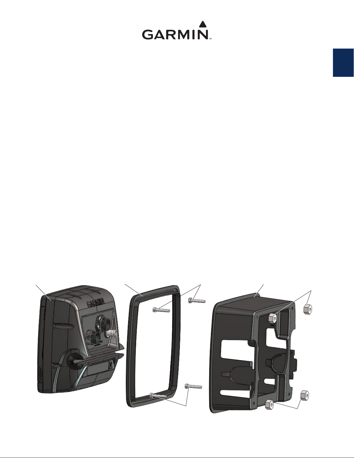
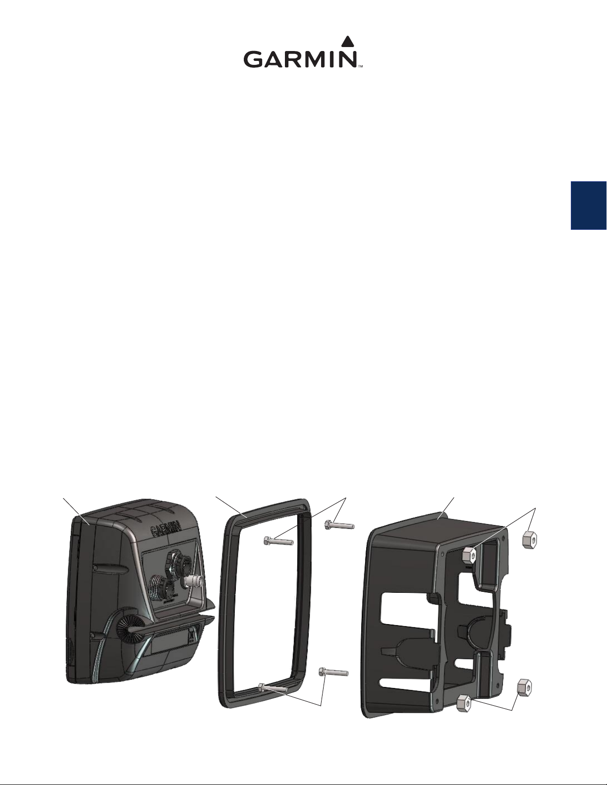
2. Assemblez le matériel de montage sur panneau (voir la gure 1) :
Fixez le joint en caoutchouc sur la face avant du boîtier de l'appareil.
•
Insérez les quatre vis à tête hexagonale dans le boîtier de l'appareil de façon à ce qu'elles dépassent à l'arrière du boîtier.
•
Utilisez les quatre écrous hexagonaux pour xer les vis à tête hexagonale sur le boîtier de l'appareil. A l'aide de la clé de 7 mm, serrez
•
les écrous sans forcer.
Glissez l'appareil dans le boîtier. (Si vous ne disposez que d'un espace limité derrière la surface de montage, cette opération peut être
•
effectuée à l'étape 3.)
Si l'unité est insérée correctement, elle s'enclenche parfaitement dans le boîtier de l'appareil.
•
Connectez le faisceau de câbles, l'antenne GPS et l'antenne XM (le cas échéant) à l'appareil. (Si nécessaire, cette opération peut
•
également être effectuée à l'étape 3.)
Appareil
Joint en caoutchouc
Vis à tête hexagonale
Boîtier de l'appareil
Ecrous hexagonaux
FR
Vis à tête hexagonale
Figure 1
octobre 2007 Réf. 190-00553-01 Rév. B Imprimé à Taiwan
Ecrous hexagonaux
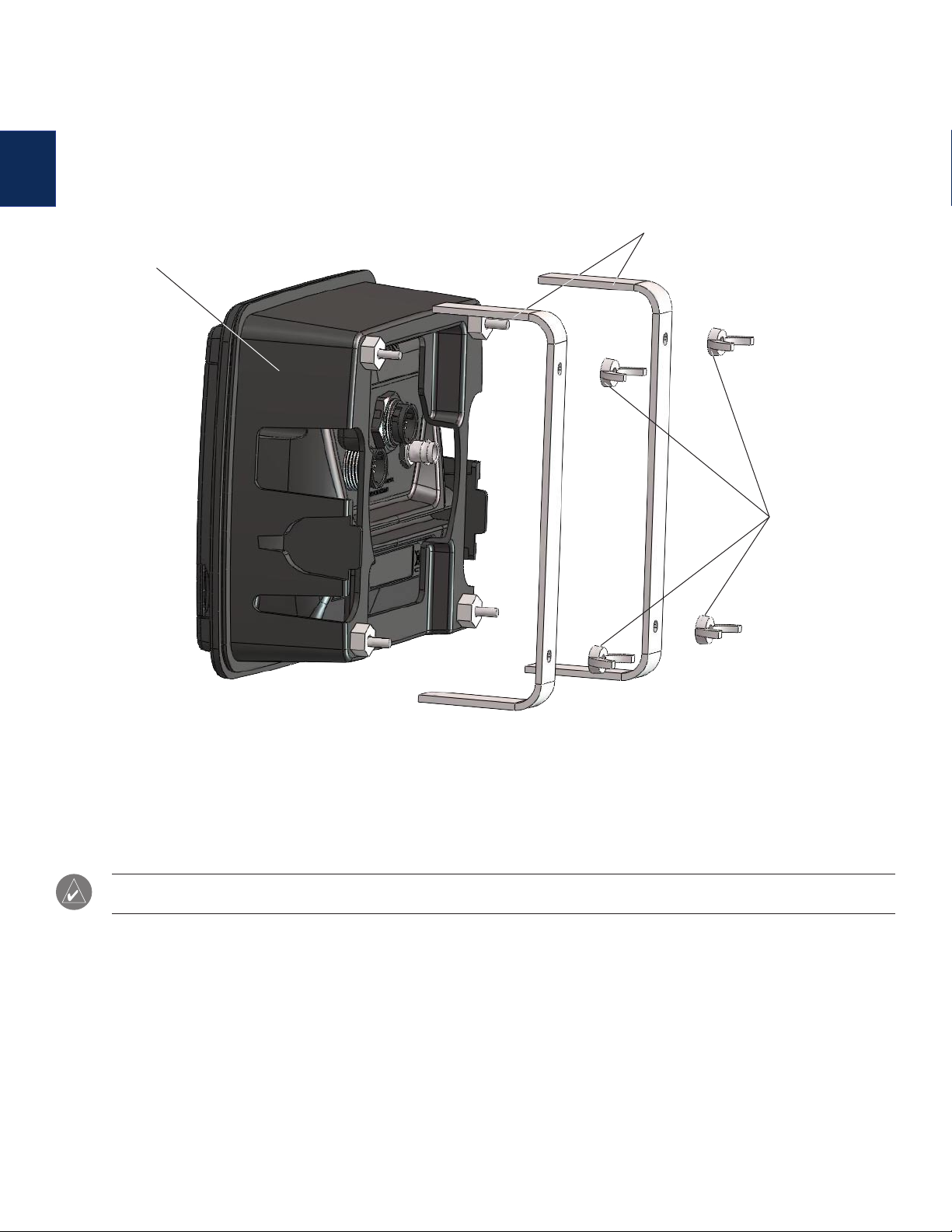
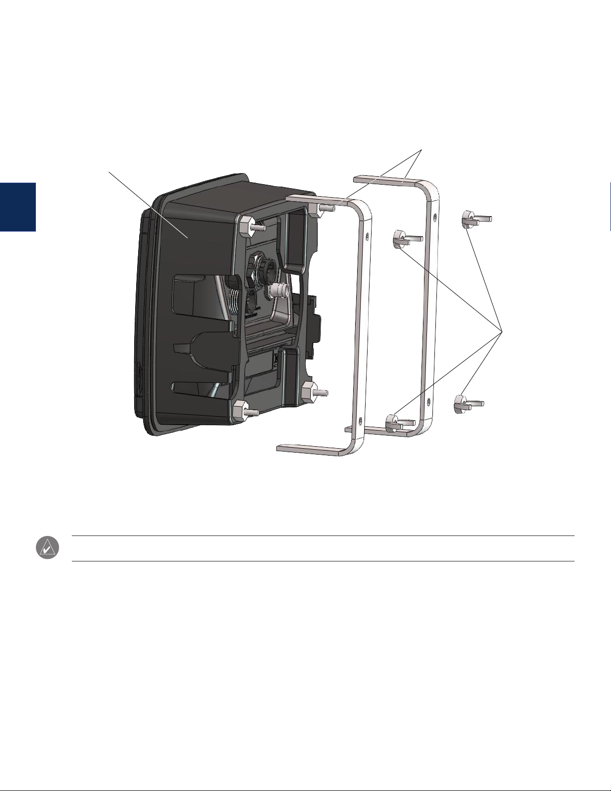
3. Installez l'appareil dans l'ouverture (voir la gure 2) :
Placez le boîtier de l'appareil dans le trou que vous venez de découper dans la surface de montage.
•
Glissez les supports de tension de la base sur les vis à tête hexagonale et xez-les à l'aide des quatre écrous à oreilles.
•
Serrez les quatre écrous à oreilles pour xer le boîtier de l'appareil sur la surface de montage. Veillez à ne pas serrer les écrous outre
•
FR
mesure.
Si vous ne l'avez pas fait lors de l'étape 2, connectez le faisceau de câbles à l'appareil, puis glissez l'appareil dans le boîtier jusqu'à
•
ce qu'il s'enclenche parfaitement.
Appareil assemblé et matériel
de montage sur panneau
Supports de xation
Ecrous à oreilles
Figure 2
REMARQUE : vous devez connecter le faisceau de câbles à l'alimentation du bateau ainsi qu'à l'antenne GPS, l'antenne XM (le cas échéant) et à la
sonde (le cas échéant), conformément aux instructions d'installation fournies avec l'appareil.
Installazione del kit opzionale per il montaggio a incasso
Questo kit consente di eseguire l'installazione a incasso dell'unità GPSMAP serie 500 su un pannello piatto.
Selezionare una posizione di installazione di dimensioni appropriate per l'unità.
•
Per determinare se la posizione è adatta, utilizzare il modello per il montaggio a incasso fornito.
•
Vericare che tutti i cavi raggiungano la posizione di montaggio dell'unità.
•
Durante le operazioni di trapanatura, taglio o carteggiatura, indossare occhiali di protezione e una maschera antipolvere.
•
Componenti di montaggio inclusi - (1) alloggiamento unità, (1) guarnizione in gomma, (2) staffe per montaggio in tensione, (4) bulloni
esagonali, (4) dadi esagonali e (4) dadi ad alette.
Strumenti (non inclusi) - Trapano, punta da trapano da 10 mm (3/8"), sega e chiave inglese da 7 mm (9/32").
Per installare il kit per il montaggio a incasso:
1. Eseguire il taglio per l'apertura:
Il retro del modello per il montaggio a incasso è adesivo. Rimuovere la striscia protettiva e applicare il modello nel punto in cui si
•
desidera montare l'unità.
Utilizzando una punta da 10 mm (3/8"), praticare con i fori guida indicati sul modello per iniziare a tagliare la supercie di montaggio.
•
Utilizzando la sega, tagliare la supercie di montaggio all'interno della linea indicata sul modello. Prestare particolare attenzione
•
quando si pratica di questo foro, poiché lo spazio tra l'alloggiamento per l'unità e le staffe per il montaggio in tensione è estremamente
ridotto. Tagliare leggermente all'interno della linea indicata, quindi carteggiare o limare il pannello no a ottenere un posizionamento
ottimale.
2. Assemblare i componenti per il montaggio a incasso (vedere la gura 1):
Fissare la guarnizione in gomma al lato anteriore dell'alloggiamento dell'unità.
•
Inserire i quattro bulloni esagonali nell'alloggiamento dell'unità in modo che fuoriescano sul lato posteriore.
•
Utilizzare i quattro dadi esagonali per ssare i bulloni all'alloggiamento. Mediante la chiave inglese da 7 mm (9/32"), serrare i dadi
•
senza stringerli eccessivamente.
Inserire l'unità nell'alloggiamento (se lo spazio a disposizione dietro alla supercie di montaggio è limitato, è possibile effettuare
•
questa operazione al punto 3).
Quando l'unità è inserita correttamente, scatta in posizione all'interno dell'alloggiamento.
•
Collegare i cavi, l'antenna GPS e l'antenna XM (se disponibile) all'unità (se necessario, è possibile effettuare questa operazione al punto 3).
•
Unità
Guarnizione in gomma
Bulloni esagonali
Alloggiamento unità
Dadi esagonali
IT
Bulloni esagonali
Figura 1
ottobre 2007 Codice 190-00553-01 Rev. B Stampato a Taiwan
Dadi esagonali
3. Installare l'unità nell'apertura (vedere la gura 2):
Posizionare l'alloggiamento dell'unità nel foro praticato sulla supercie di montaggio.
•
Inserire le staffe per il montaggio in tensione sui bulloni esagonali e ssare con i quattro dadi ad alette.
•
Serrare i quattro dadi ad alette per ssare l'alloggiamento dell'unità alla supercie di montaggio. Prestare attenzione a non stringere
•
eccessivamente i dadi.
Collegare i cavi all'unità (se non è stato fatto al punto 2), quindi inserire l'unità nell'alloggiamento nché non scatta in posizione.
•
IT
Componenti per il montaggio
a incasso e unità assemblati
Staffe per il montaggio in tensione
Dadi ad alette
Figura 2
NOTA: per visualizzare le istruzioni di installazione fornite con l'unità, è necessario collegare i cavi all'alimentazione dell'imbarcazione, all'antenna
GPS, all'antenna XM (se disponibile) e al trasduttore (se disponibile).
Installieren des Einbau-Montagesatzes
Verwenden Sie diesen Montagesatz, um ein Gerät der GPSMAP 500-Serie bündig in eine Tafel einzubauen.
Wählen Sie einen für die Größe des Geräts passenden Einbauort aus.
•
Verwenden Sie die Montageschablone, um diesen Einbauort zu bestimmen.
•
Stellen Sie sicher, dass alle Kabel bis an den Einbauort des Geräts heranreichen.
•
Tragen Sie beim Bohren, Sägen und Schleifen stets Schutzbrille und Staubmaske.
•
Mitgelieferte Befestigungsteile: (1) Gerätegehäuse, (1) Gummidichtung, (2) Halterungen, (4) Sechskantschrauben, (4) Sechskantmuttern und
(4) Flügelmuttern.
Werkzeuge (nicht im Lieferumfang enthalten): Bohrmaschine, Bohrer (3/8", 10 mm), Bogensäge und Schlüssel (9/32", 7 mm).
So installieren Sie den Einbau-Montagesatz:
1. Sägen Sie die Öffnung aus:
Auf der Rückseite der Schablone für die bündige Montage bendet sich Klebstoff. Entfernen Sie den Schutzrand und wenden Sie die
•
Schablone auf die Stelle an, an der Sie das Gerät befestigen möchten.
Beginnen Sie mit dem Aussägen der Öffnung. Bohren Sie dazu mit einem 3/8"-Bohrer (10-mm-Bohrer) an den auf der Schablone
•
aufgezeichneten Stellen vor.
Sägen Sie mit der Bogensäge entlang der Innenseite der auf der Schablone aufgezeichneten Linie. Sägen Sie das Loch sehr
•
sorgfältig aus, denn zwischen dem Gerätegehäuse und den Halterungen ist nur ein geringer Abstand vorgesehen. Sägen Sie etwas
innerhalb der aufgezeichneten Linie, und schleifen oder feilen Sie die Tafel nach Bedarf ab, bis die richtige Passung erreicht ist.
2. Setzen Sie die Befestigungsteile zusammen (siehe Abbildung 1):
Befestigen Sie die Gummidichtung an der Vorderseite des Gerätegehäuses.
•
Setzen Sie die vier Sechskantschrauben so in das Gerätegehäuse ein, dass sie an der Rückseite herausragen.
•
Befestigen Sie die Sechskantschrauben mit den Sechskantmuttern am Gerätegehäuse. Ziehen Sie die Muttern mit dem 9/32"-
•
Schlüssel (7-mm-Schlüssel) an, jedoch nicht zu fest.
Schieben Sie das Gerät in das Gerätegehäuse. (Sollte hinter der Montageoberäche nur wenig Platz sein, so kann dies auch in
•
Schritt 3 erfolgen.)
Wenn das Gerät korrekt eingeschoben wird, rastet es im Gerätegehäuse ein.
•
Schließen Sie den Kabelbaum, die GPS-Antenne und die XM-Antenne (sofern vorhanden) an das Gerät an. (Falls erforderlich, kann
•
dies auch in Schritt 3 erfolgen.)
Gerät
Gummidichtung
Sechskantschrauben
Gerätegehäuse
Sechskantmuttern
DE
Sechskantschrauben
Abbildung 1
Oktober 2007 Teilenummer 190-00553-01 Rev. B Gedruckt in Taiwan
Sechskantmuttern
3. Montieren Sie das Gerät in der Öffnung (siehe Abbildung 2):
Schieben Sie das Gerätegehäuse in die zuvor in die Montageoberäche gesägte Öffnung.
•
Schieben Sie die Halterungen auf die Sechskantschrauben, und befestigen Sie sie mit den vier Flügelmuttern.
•
Ziehen Sie die vier Flügelmuttern an, um das Gerätegehäuse an der Montageoberäche zu befestigen. Ziehen Sie die Muttern nicht
•
zu fest an.
Sollten Sie den Kabelbaum noch nicht in Schritt 2 an das Gerät angeschlossen haben, führen Sie diesen Schritt jetzt aus. Schieben
•
Sie anschließend das Gerät in das Gerätegehäuse, bis es einrastet.
DE
Montiertes Gerät und
Halterungen
Befestigungsteile
Flügelmuttern
Abbildung 2
HINWEIS: Der Kabelbaum, die GPS-Antenne, die XM-Antenne (sofern vorhanden) und der Schwinger (sofern vorhanden) müssen gemäß den im
Lieferumfang dieses Geräts enthaltenen Installationsanweisungen an die Stromversorgung des Bootes angeschlossen werden.
Instalación del kit de montaje alineado
Utilice este kit para el montaje alineado de una unidad de la serie GPSMAP 500 en un panel plano.
Seleccione una ubicación del tamaño adecuado para la unidad.
•
Utilice la plantilla de montaje alineado proporcionada para determinar la ubicación.
•
Compruebe la longitud correcta de todos los cables hasta la ubicación de montaje de la unidad.
•
Utilice siempre gafas de seguridad y una máscara antipolvo al realizar oricios, cortes o lijados.
•
Componentes de montaje incluidos—(1) carcasa, (1) sellante de goma, (2) soportes de montaje por tensión, (4) tornillos hexagonales, (4)
tuercas hexagonales y (4) palomillas.
Herramientas (no incluidas)—taladro, broca de 3/8 pulg. (10 mm), sierra de vaivén y una llave de 9/32 pulg. (7 mm).
Para instalar el kit de montaje alineado:
1. Corte la abertura:
La plantilla para el montaje alineado es adhesiva en la parte posterior. Retire el forro protector y pegue la plantilla en el lugar donde
•
desea montar la unidad.
Con una broca de 3/8 pulg. (10 mm), perfore los oricios guía indicados en la plantilla para comenzar a cortar la supercie de instalación.
•
Con la sierra de vaivén, corte la supercie de instalación a lo largo de la parte interior de la línea indicada en la plantilla. Tenga
•
cuidado al cortar el oricio, ya que tan sólo existe un pequeño espacio libre entre la carcasa y los extremos de montaje por tensión.
Corte ligeramente por dentro de la línea indicada y, a continuación, lije o lime el panel como sea necesario para obtener un ajuste
perfecto.
2. Monte los componentes de montaje alineado (consulte la ilustración 1):
Ajuste el sellante de goma en la parte frontal de la carcasa.
•
Introduzca los cuatro tornillos hexagonales en la carcasa de forma que sobresalgan por la parte posterior.
•
Utilice las cuatro tuercas hexagonales para asegurar los tornillos hexagonales a la carcasa. Con la llave de 9/32 pulg. (7 mm), apriete
•
las tuercas, pero no en exceso.
Introduzca la unidad dentro de la carcasa deslizándola. (Si dispone de un espacio limitado por detrás de la supercie de instalación,
•
este proceso puede realizarse en el paso 3)
Cuando la unidad se inserte correctamente, se encajará en su lugar dentro de la carcasa.
•
Conecte el arnés de cableado, la antena GPS y la antena XM (si fuera necesario) a la unidad. (Este proceso también puede
•
realizarse en el paso 3, si fuera necesario)
Unidad
Sellado de goma
Tornillos hexagonales
Carcasa
Tuercas hexagonales
ES
Tornillos hexagonales
Ilustración 1
octubre de 2007 Número de publicación 190-00553-01 Rev. B Impreso en Taiwán
Tuercas hexagonales
 Loading...