

Page 1
GPSMAP 195
Pilot’s Guide
& Reference
Page 2

Page 3

INTRODUCTION
FOREWORD
This manual is written for Software Version 3.00 or above, and is not suitable for earlier
software versions.
Land Data Base Map Version 1.00 or above
GARMIN International, Inc., 1200 E. 151st Street, Olathe, KS 66062 USA
Tel: 913-397-8200 Fax: 913-397-8282
GARMIN (Europe) LTD, Unit 5, The Quadrangle, Abbey Park, Romsey, Hampshire SO51 9AQ UK
Tel: 011-44-1794-519944 Fax: 011-44-1794-519222
GARMIN (Asia) Corp., 3F, No. 1, Lane 45, Pao Hsing Road, Hsin Tien, Taipei, Taiwan R.O.C.
Tel: 011-886-02-2917-4107 Fax: 011-886-02-2917-1758
Web Site Address: www.garmin.com
NavData® is a registered trademark of Jeppesen, Inc.
© 1996-1999 GARMIN Corporation. All rights reserved. Except as expressly provided
herein, no part of this manual may be reproduced, copied, transmitted, disseminated,
downloaded or stored in any storage medium, for any purpose without the express prior
written consent of GARMIN Corporation. GARMIN hereby grants permission to download a single copy of this manual and of any revision to this manual onto a hard drive or
other electronic storage medium to be viewed and to print one copy of this manual or of
any revision hereto, provided that such electronic or printed copy of this manual or revision must contain the complete text of this copyright notice and provided further that
any unauthorize commercial distribution of this manual or any revision hereto is strictly
prohibited.
GARMIN, GPSMAP, AutoLocate, TracBack and Spell’N’Find are registered trademarks of
GARMIN Corporation and may only be used with permission. All rights are reserved.
Information in this document is subject to change without notice. GARMIN reserves
the right to change or improve its products and to make changes in the content without
obligation to notify any person or organization of such changes or improvements.
1
June 1999 Part #190-00097-00 Rev. C Printed in Taiwan.
Page 4

INTRODUCTION
The GPS system is operated by the United States government, which is solely
responsible for its accuracy and maintenance. The system is subject to changes which
could affect the accuracy and performance of all GPS equipment. Although the GARMIN
GPSMAP 195 is a precision electronic NAVigation AID (NAVAID), any NAVAID can be
misused or misinterpreted and, therefore, become unsafe.
Use the GPSMAP 195 at your own risk. To reduce the risk of unsafe operation,
carefully review and understand all aspects of this Owner’s Manual—and thoroughly
practice operation using the simulator mode prior to actual use. When in actual use,
carefully compare indications from the GPSMAP 195 to all available navigation sources,
including the information from other NAVAIDs, visual sightings, charts, etc. For safety,
always resolve any discrepancies before continuing navigation.
NOTE: This device complies with Part 15 FCC limits for Class B digital devices. This equipment
generates, uses and can radiate radio frequency energy and, if not installed and used in accordance
with the instructions, may cause harmful interference to radio communications. Furthermore, there
is no guarantee that interference will not occur in a particular installation. If this equipment does
cause harmful interference, the user is encouraged to try to correct the interference by relocating the
equipment or connecting the equipment to a different circuit. Consult an authorized dealer or other
qualified technician for additional help if these remedies do not correct the problem.
CAUTION
?
#
Operation of this device is subject to the following conditions: (1) This device may not cause harmful interference, and (2) this device must accept any interference received, including interference that
may cause undesired operation.
The GPSMAP 195 does not contain any user-serviceable parts. Repairs should only
be made by an authorized GARMIN service center. Unauthorized repairs or modifications could void your warranty and your authority to operate this device under Part 15
regulations.
!
WARNING: The moving map display is an aid to navigation and is designed to facilitate the
use of authorized government charts, not replace them. Only official government charts and
notices to airmen (NOTAMs) contain all information needed for safe navigation—and, as
always, the user is responsible for their prudent use.
#
2
Page 5

INTRODUCTION
LIMITED WARRANTY
GARMIN Corporation warrants this product to be free from defects in materials and
workmanship for one year from the date of purchase. GARMIN will, at its sole option,
repair or replace any components which fail in normal use. Such repairs or replacement
will be made at no charge to the customer for parts or labor. The customer is, however,
responsible for any transportation costs. This warranty does not cover failures due to
abuse, misuse, accident or unauthorized alteration or repairs.
THE WARRANTIES AND REMEDIES CONTAINED HEREIN ARE EXCLUSIVE, AND
IN LIEU OF ALL OTHER WARRANTIES EXPRESSED OR IMPLIED, INCLUDING ANY
LIABILITY ARISING UNDER WARRANTY OF MERCHANTABILITY OR FITNESS FOR
A PARTICULAR PURPOSE, STATUTORY OR OTHERWISE. THIS WARRANTY GIVES
YOU SPECIFIC LEGAL RIGHTS, WHICH MAY VARY FROM STATE TO STATE.
IN NO EVENT SHALL GARMIN BE LIABLE FOR ANY INCIDENTAL, SPECIAL,
INDIRECT OR CONSEQUENTIAL DAMAGES, WHETHER RESULTING FROM THE
USE, MISUSE OR INABILITY TO USE THIS PRODUCT OR FROM DEFECTS IN THE
PRODUCT. SOME STATES DO NOT ALLOW THE EXCLUSION OF INCIDENTAL OR
CONSEQUENTIAL DAMAGES, SO THE ABOVE LIMITATIONS MAY NOT APPLY TO
YOU.
GARMIN is fully committed to your satisfaction as a customer. If you have any questions
regarding the GPSMAP 195, please contact our customer service department at:
GARMIN International, Inc.
1200 East 151st Street
Olathe, KS 66062-3426
PH: 913-397-8200
FAX: 913-397-8282
To obtain warranty service, call the GARMIN Customer Service department for a returned
merchandise tracking number. The unit should be securely packaged with the tracking number
clearly marked on the outside of the package, and sent freight pr epaid and insur ed to a GARMIN
warranty service station. A copy of the original sales receipt is required as the proof of purchase
for warranty repairs. GARMIN retains the exclusive right to repair or replace the unit or software or offer a full refund of the purchase price at its sole discretion. SUCH REMEDY SHALL
BE YOUR SOLEANDEXCLUSIVEREMEDY FOR ANY BREACH OF WARRANTY.
3
Page 6

INTRODUCTION
Designed for detailed electronic charting and simple operation, the GARMIN GPSMAP
195 is a powerful navigation device that can help guide you during flights anywhere in
the world:
Precision Performance
• High-contrast, four-level gray LCD screen
• Twelve parallel channel receiver tracks and uses up to 12 satellites simultaneously
for fast, accurate positioning
• Differential-ready— just add an optional differential beacon receiver (such as
GARMIN’s GBR 21), or any other device providing standard RTCM SC-104
corrections, for under 10 meter accuracy
Advanced Navigating and Plotting
• Internal Jeppesen®database includes detailed airport information: runway length,
surface and lighting, airport position and elevation, communication frequencies
and fuel services, as well as information about VORs, NDBs, intersections, flight
service stations (FSS) and air route traffic control centers (ARTCC)
• Built-in basemap covering coastlines, lakes, rivers, interstate highways, U.S.
highways, major thoroughfares— optimized for 3000 through 20 nm scales
and usable down to 1/10 nm.
• Three-dimensional controlled and special-use airspace data with multiple airspace
incursion warnings
• Built-in final course segment approaches for all published ILS, localizer, RNAV,
GPS, VOR and NDB approaches
• Graphic HSI display for navigation guidance shows current conditions at a glance
• On-screen “point and shoot” GOTO simplifies destination selection
• One-button nearest airport search
• 250 alphanumeric waypoints with selectable icons and comments
• 250 symbol waypoints with selectable icons
• 20 reversible routes with up to 30 waypoints each
• On-screen point-to-point distance and bearing calculations
• TracBack™ route feature allows you to quickly retrace your track log to a starting
position
• E6-B features to determine density altitude, true airspeed, winds aloft, headwind/
tailwind components, trip and fuel planning, weight and balance
• Enhanced vertical navigation feature indicates time and vertical speed to target,
glide ratio and provides vertical guidance from the graphic HSI display
• Built-in simulator mode makes learning new features fun and easy
CAPABILITIES
4
Page 7
INTRODUCTION
GPsMAP195
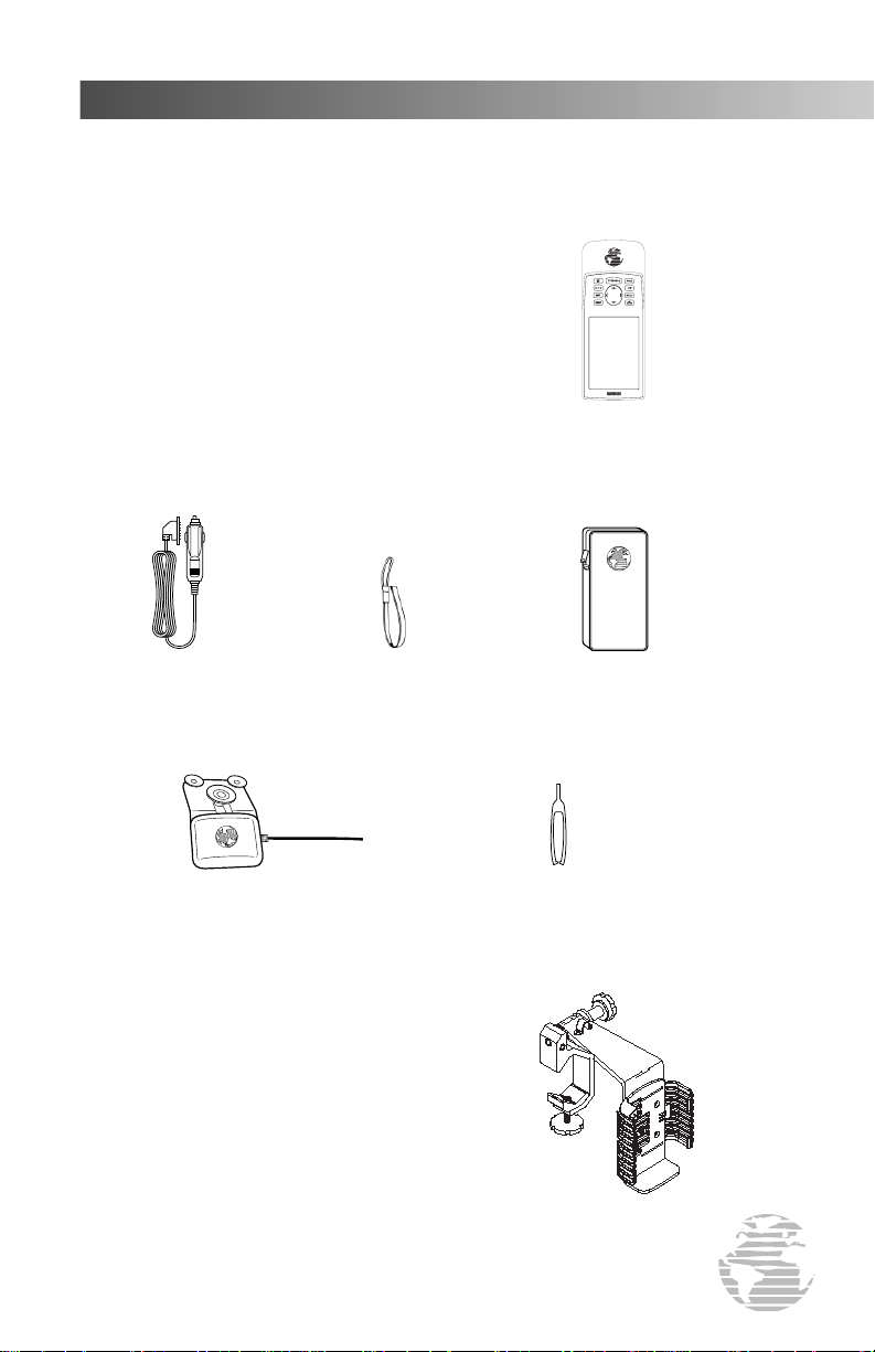
PACKING LIST
Before you get started, please check to see that your GPSMAP 195 package includes
the following items. If any parts are missing, contact your GARMIN dealer immediately.
Standard Package:
• GPSMAP 195 Unit
• AA Battery Pack
• Cigarette Lighter Adapter
• Wrist Strap
• Carrying Case
• Remote Antenna with 8’ Cable
• Cartridge Removal Tool
• Yoke Mount
• Owner’s Manual
• Quick Reference Guide
GPSMAP 195 Receiver
(AA Battery Pack attached)
Cigarette Lighter Adapter
External Antenna w/ 8’ Cable
Optional Accessories:
• PC Interface Cable
• Database Update (uses PC Interface Cable)
• Power/Data Cable
• NiCad Battery & Charger Kit
• PC Software Kit
• MCX-to-BNC Adapter (for connection to an
outside antenna)
• Mapping Datacards: Americas (for use in International
195 versions), International (for use in Americas 195
versions), Alaska, Canada East, Canada West
Wrist Strap
Carrying Case
Cartridge Removal Tool
Yoke Mount
5
Page 8

INTRODUCTION
Congratulations on choosing one of the most advanced aircraft navigation systems
available today! The GARMIN GPSMAP 195 combines the proven performance of
GARMIN’s twelve parallel channel GPS receiver with detailed cartography for an unsurpassed moving map display wherever you fly. To get the most from your new GPSMAP
195, take the time to read through this owner’s manual and lear n the operating procedures for your unit. This manual is divided into two main sections for your convenience.
Section One: Takeoff Tour introduces the basic features of the GPSMAP 195. This
section is a “getting started” guide to acquaint you with the unit’s major features. This
will provide you with the basic working knowledge necessary to use the unit to its full
potential. In this section you will learn how to power the unit on and obtain a position
fix. Then you will place the GPSMAP 195 in “Simulator Mode” for a sample trip, which
will introduce many of the unit’s capabilities.
Section Two: Reference provides a detailed reference to all the features and operations
of the GPSMAP 195. This allows you to concentrate on a specific topic quickly, without
reading through entire sections of text. You may also wish to refer to this section for
information about the more advanced features not covered in Section One.
“How To” Index
The list below is provided to help you quickly find some of the more important
procedures you will use on your new GPSMAP 195.
TO DO THIS: SEE PAGE(S):
Turn the unit on or off . . . . . . . . . . . . . . . . . . . . . . . . . . . . . . . . . . . . . . . . . . . . . 14
Initialize the receiver (first time use). . . . . . . . . . . . . . . . . . . . . . . . . . . . . . . . . 12-14
Enter data using the rocker keypad . . . . . . . . . . . . . . . . . . . . . . . . . . . . . . . . . . . . 11
Use menus . . . . . . . . . . . . . . . . . . . . . . . . . . . . . . . . . . . . . . . . . . . . . . . . . . . 10-11
Adjust screen contrast or backlighting . . . . . . . . . . . . . . . . . . . . . . . . . . . . . . . . . . 15
Reconfigure displayed data on the map and/or HSI pages . . . . . . . . . . . . . . 23, 55, 61
Display nearest airports list . . . . . . . . . . . . . . . . . . . . . . . . . . . . . . . . . . . . . . . 20, 41
Display the database information (location/runways/frequencies) . . . . . . . . . . . 27-35
for an airport or navaid
Select an airport or navaid by identifier . . . . . . . . . . . . . . . . . . . . . . . . . . . . . . 27-28
Select airport or navaid by facility name or city name. . . . . . . . . . . . . . . . . . . . . . . 28
(when the identifier isn’t known)
Select a destination (GOTO) . . . . . . . . . . . . . . . . . . . . . . . . . . . . . . . . . . . . . . 21, 44
Create and use a route (flight plan). . . . . . . . . . . . . . . . . . . . . . . . . . . . . . . . . . 75-77
Review airspace warnings and information . . . . . . . . . . . . . . . . . . . . . . . . . 24-25, 67
Disable airspace alarms . . . . . . . . . . . . . . . . . . . . . . . . . . . . . . . . . . . . . 64-65, 67-68
Change CDI scale . . . . . . . . . . . . . . . . . . . . . . . . . . . . . . . . . . . . . . . . . . . . . . . . . 23
Pan ahead on the map display . . . . . . . . . . . . . . . . . . . . . . . . . . . . . . . . . . 19, 51-52
Save present position as a user-defined waypoint . . . . . . . . . . . . . . . . . . . . . . . . . . 38
Change units of measure (statute, nautical, metric). . . . . . . . . . . . . . . . . 64-65, 69-70
Change position format (degrees/minutes/seconds, . . . . . . . . . . . . . . . . 64-65, 70-71
degrees/minutes, etc.)
Change displayed time (zulu or local). . . . . . . . . . . . . . . . . . . . . . . . . . . . . 64-65, 73
Use the remote antenna. . . . . . . . . . . . . . . . . . . . . . . . . . . . . . . . . . . . . . . . . . . . . 93
6
Install the yoke mount. . . . . . . . . . . . . . . . . . . . . . . . . . . . . . . . . . . . . . . . . . . 91-92
Change batteries. . . . . . . . . . . . . . . . . . . . . . . . . . . . . . . . . . . . . . . . . . . . . . . . . . 94
PREFACE
Page 9

INTRODUCTION
TABLE OF CONTENTS
Forward . . . . . . . . . . . . . . . . . . . . . . . . . . . . . . . . . . . . . . . . . . . . . .1
Caution . . . . . . . . . . . . . . . . . . . . . . . . . . . . . . . . . . . . . . . . . . . . . . .2
Limited Warranty . . . . . . . . . . . . . . . . . . . . . . . . . . . . . . . . . . . . . . .3
Capabilities . . . . . . . . . . . . . . . . . . . . . . . . . . . . . . . . . . . . . . . . . . . .4
Packing List . . . . . . . . . . . . . . . . . . . . . . . . . . . . . . . . . . . . . . . . . . .5
Preface . . . . . . . . . . . . . . . . . . . . . . . . . . . . . . . . . . . . . . . . . . . . . . .6
Table of Contents . . . . . . . . . . . . . . . . . . . . . . . . . . . . . . . . . . . . . . .7
SECTION ONE: Takeoff Tour . . . . . . . . . . . . . . . . . . . . . . . . . .8-26
GPSMAP 195 Features, Keypad Usage, Using Menus, Entering Data,
Initializing the Receiver, Turning On/Off, Descriptions of Main Pages
SECTION TWO: Reference . . . . . . . . . . . . . . . . . . . . . . . . . . .27-89
Waypoint Categories/Information . . . . . . . . . . . . . . . . . . . . . . . . .27-40
Nearest Waypoints and Airspace Information . . . . . . . . . . . . . . . . .41-43
Going to a Destination and Using GOTO Options . . . . . . . . . . . . .44-45
Status Page and Options . . . . . . . . . . . . . . . . . . . . . . . . . . . . . . . .46-48
Position Page and Options . . . . . . . . . . . . . . . . . . . . . . . . . . . . . .49-50
Map Page, Options, and Using the Cursor . . . . . . . . . . . . . . . . . . .51-58
HSI Page and Options . . . . . . . . . . . . . . . . . . . . . . . . . . . . . . . . .59-61
Active Route Page and Options . . . . . . . . . . . . . . . . . . . . . . . . . . .62-63
Main Menu and Setup Menus . . . . . . . . . . . . . . . . . . . . . . . . . . . .64-74
Routes, Approaches, and TracBack . . . . . . . . . . . . . . . . . . . . . . . .75-82
Timers . . . . . . . . . . . . . . . . . . . . . . . . . . . . . . . . . . . . . . . . . . . . .82-83
Vertical Navigation . . . . . . . . . . . . . . . . . . . . . . . . . . . . . . . . . . . .84-85
Density Altitude, Winds Aloft, Trip Planning, Weight & Balance . . .86-89
Appendix A: Accessories and Installation . . . . . . . . . . . . . . .91-96
Appendix B: Wiring and Interface . . . . . . . . . . . . . . . . . . . . .97-98
Appendix C: Specifications . . . . . . . . . . . . . . . . . . . . . . . . . . . . .99
Appendix D: Messages . . . . . . . . . . . . . . . . . . . . . . . . . . . . .100-101
Appendix E: Abbreviations . . . . . . . . . . . . . . . . . . . . . . . . .102-103
Appendix F: Glossary of Navigation Terms . . . . . . . . . . . .104-105
Appendix G: Map Datums . . . . . . . . . . . . . . . . . . . . . . . . . .106-107
Appendix H: Index . . . . . . . . . . . . . . . . . . . . . . . . . . . . . . .108-110
7
Page 10
TAKEOFF TOUR
GOTO
ZOOM
WPT
NRST
QUIT
PAGE
MENU
EDIT
ENTER
TEXT FIELDS
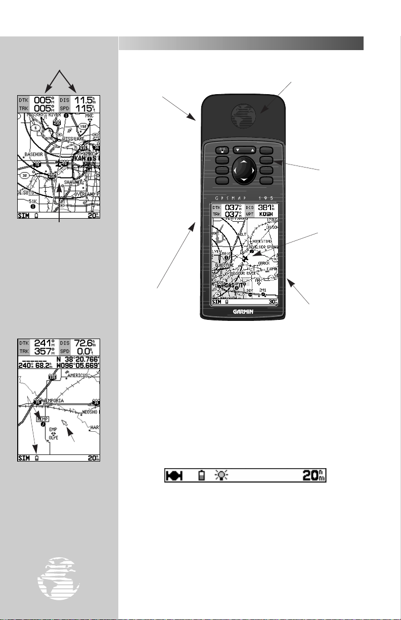
THE GPSMAP 195 FEATURES
MAP DISPLAY
GRAPHIC
The information displayed on your GPSMAP
195’s screen is also referred
to as a “page”. A page can
include graphics, text or
both.
EXTERNAL ANTENNA
BUILT-IN ANTENNA
CONNECTOR
KEYPAD
DISPLAY
SCREEN
POWER/DATA
CONNECTOR
(Back Side)
BATTERY PACK
(Back Side)
The GPSMAP 195 features a 10-key keypad and a 4-level gray
scale LCD display. Both the display and keypad may be illuminated for nighttime operation.
ICONS
Graphics displayed on a
CURSOR
page include detailed map
information, icons and a
cursor.
8
Information which appears on the display is referred to as a
page. A page can include graphics, text or both. The graphic
information may include a detailed map, icons and a cursor.
Icons are symbols which appear on the screen and represent
airports, navaids, user waypoints, etc. For example, your present
position is represented on the map by an airplane icon.
At the bottom of each page is a status bar. Icons appear on the
status bar to indicate valid position, battery level, and backlighting. The status bar is also used to show scale settings and
messages.
Page 11

KEYPAD USAGE
P
J
G
N
W
3-level screen backlighting.
returns display from a submenu page to a
main page.
you to select the destination waypoint.
VORs, NDBs, or intersections, plus nearest
FSS and center frequencies. Provides specialuse airspace detail during an airspace
incursion. Press twice to return automatically
to nearest airport list.
database or user waypoint from memory. Press
twice to capture your present position and
save as a waypoint.
A
R
data. Also controls the movement of the
cursor on the map page.
Turns the unit on and off and controls
Scrolls the main pages in sequence and
Displays the GOTO waypoint page, allowing
Displays a list of nine nearest airports,
Retrieves airport or navaid information from
Adjusts the map and HSI scales up or down.
Used to select (highlight) options and enter
TAKEOFF TOUR
The GPSMAP 195’s
advanced keypad system is
designed to allow for fast,
convenient selection of
navigation options and data
entry.
The Takeoff Tour will
introduce you to the keypad
keys and provide a “hands
on” lesson in using the
GPSMAP 195. We strongly
encourage you to read the
Takeoff Tour before using
your unit for actual
navigation.
The GPSMAP 195 Quick
Reference Card contains
helpful tips on using the
unit and performing
various navigation tasks.
It’s a good idea to keep the
Quick Reference Card
nearby when using this new
navigation tool.
Q
O
T
Returns display to a previous page or
restores a data field’s previous value.
Displays context-sensitive options window.
Press twice to display main menu page.
Activates highlighted fields. Confirms menu
options and data entry.
9
Page 12
TAKEOFF TOUR
Menus are availabe to
reconfigure many GPSMAP
195 screens and change system settings.
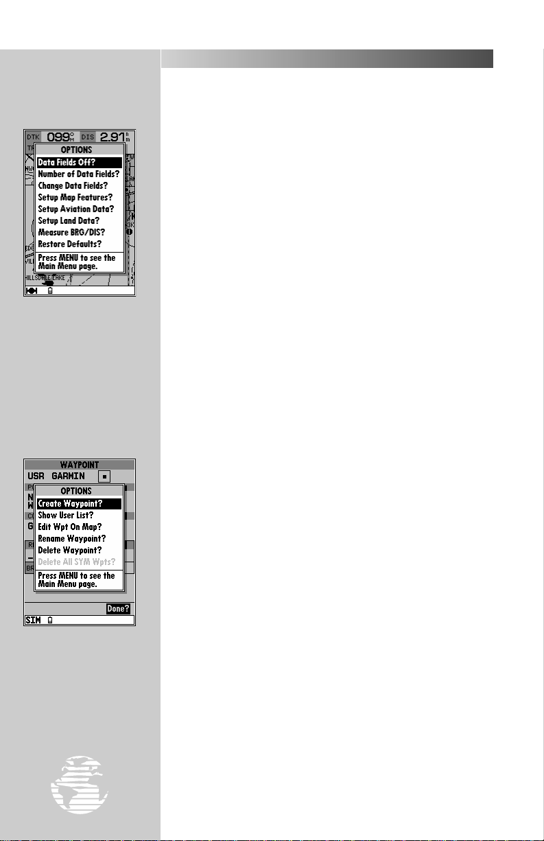
USING MENUS
Many features of the GPSMAP 195 are menu driven. This makes
learning and using your new GPS receiver a simple process. Some
pages can also be custom tailored to your preferences by changing the
information and/or layout of the display.
To reconfigure the page currently displayed:
1. Press
2. Select the desired option using UP/DOWN arrows on the
3. Press
4. In some cases, a list may appear with even more options available.
If this occurs, select the desired option using the
press
For example, the map page can be changed from map & data to
map only (and vice versa) by pressing
(On)?’ and pressing
Some keys can perform a variety of functions. The
used to display the options for the function key you have selected.
to view the options for that page.
O
to confirm your selection.
T
.
T
O
.
T
keypad.
R
keypad and
R
, selecting ‘Data Fields Off
key is also
O
The menu key is also
used to display options for a
given function key. The
key options menu is
∑∑
used to create, edit, delete
and rename user waypoints.
To select additional options for a given function key (G,
or N):
1. Press that key, followed by
For example, by pressing Wfollowed by O, you can easily
select from a number of user waypoint options: create, edit, delete
and rename.
A data field is a location on the page which provides specific
information. Some data fields on certain pages can be changed to
display a variety of data types. These data fields are also part of the
menu process since the available options are listed for you to choose
from.
To select a data field option:
1. Select ‘Change Data Fields?’ from an options menu.
2. Highlight the data field you wish to change using the
3. Press
4. Select the desired option using the
5. Press
to display the available options for that data field.
T
.
T
O
.
R
keypad.
R
W
keypad.
10
Page 13
USING MENUS (cont.)
A main menu is provided to make changes to system settings.
Selecting miles per hour instead of knots, using the built-in simulator mode, creating routes or performing E6-B calculations are all
accomplished from the main menu.
To view the main menu:
1. Press the
ENTERING DATA
You may enter data, such as airport identifiers and user waypoint
coordinates, on certain pages. To enter data, you must first highlight
(using the
A rule-of-thumb to remember: The data entry process begins and ends by
pressing
T
key twice.
O
keypad) the area on the display where it will be placed.
R
. The Rkeypad is then used to enter the actual data.
TAKEOFF TOUR
The rocker keypad is
used to enter an airport
identifier. To start, highlight the data entry field
††
.
and press
For example, to enter “KIXD” as a destination airport:
1. Display the select GOTO destination page by pressing the
2. Highlight the data entry field using the
3. Press
4. Use the UP/DOWN arrows of the
character.
5. Use the RIGHT arrow of the
character. If you make a mistake, back up with the LEFT arrow. To
clear the data field entirely, press the LEFT arrow repeatedly until the
field is blank.
6. Repeat steps 3 and 4 until the identifier is selected (see right).
7. Press
.
T
to accept the identifier.
T
R
keypad.
R
keypad to select the first
R
keypad to move to the next
G
key.
Enter the airport identifier using the
UP/DOWN arrows to
change characters or
RIGHT arrow to move to
the next character, then
press
††
keypad,
RR
when finished.
11
Page 14
TAKEOFF TOUR
The GPSMAP 195’s view
of the sky will determine
how fast you get a position
fix, or if you get a fix at all.
GPS signals do not pass
through large obstructions
made of wood or metal.
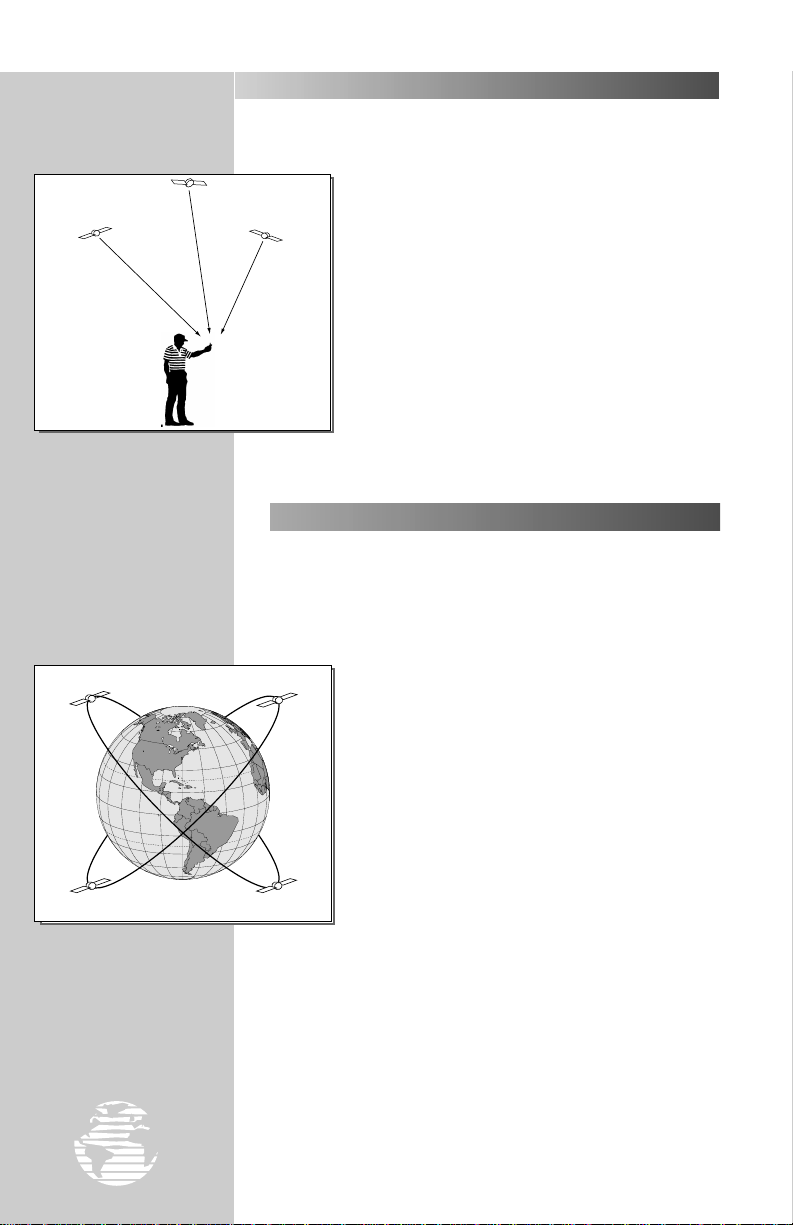
ACQUIRING SATELLITE SIGNALS
Because the GPSMAP 195 relies on satellite signals to
provide you with navigation guidance, the receiver’s antenna needs to
have an unobstructed, clear view of the sky for best performance. What exactly does this mean? In a nutshell,
the antenna’s view of the sky will generally determine
how fast you get a position fix, or if you get a fix at all.
GPS signals are relatively weak and do not travel through
large obstructions made of metal or wood, for example.
Once the GPS has calculated a position fix, you’ll
typically have anywhere from five to nine satellites in
view. Your GPSMAP 195 will continuously use all satellites in view to update your position. If some of the satellites in view are blocked, or “shaded,” the receiver can
use the remaining satellites to maintain the position fix.
Although a GPS receiver needs four satellites to provide
a three-dimensional fix (includes altitude), the GPSMAP
195 may obtain a 2D fix with only three satellites.
INITIALIZING THE RECEIVER
Take your GPSMAP 195 outside and find a large, open area (away
from towers, buildings and hangars) that has a clear view of the sky
from horizon to horizon. Hold the receiver at a comfortable height, at
arm’s length from your body, with the built-in antenna (the top part
above the display) parallel to the ground.
The 24 GPS satellites are
constantly moving, orbiting
the earth twice a day. In
order to calculate your position, the GPS receiver needs
to continuously “see” at
least three satellites.
12
Your GPSMAP 195 calculates your position and
movement by tracking signals sent from GPS satellites.
Each of the 24 GPS satellites circle the earth twice a day
in a very precise orbit and transmit information back to
earth. In order to determine a position fix, your GPS
receiver needs to continuously “see” at least three
satellites.
Because a GPS receiver can only see satellites above
the horizon, it needs to know what satellites to look for
at any given time. By using an almanac (a timetable of
satellite numbers and their orbits) stored in the receiver’s
memory, the GPSMAP 195 can determine the distance
and position of any GPS satellite.
To use this almanac data, your GPSMAP 195 needs to know where
you are, or be given the opportunity to “find itself.” Once you
initialize the unit to this position, thereafter the GPSMAP 195 will
normally compute a fix within a few minutes. Remember, this
process is only necessary under the following conditions:
• First-time use from the factory;
• The receiver has been moved over 500 miles from the last
calculated position with power off; or
• The receiver’s memory has been cleared and all stored data
has been lost.
Page 15
TAKEOFF TOUR
INITIALIZING THE RECEIVER (cont.)
The first time you power up your new GPSMAP 195 is an
important step in getting the best possible GPS performance. The
receiver must be given an opportunity to collect satellite data and
establish its present position. To ensure proper initialization, the
GPSMAP 195 is shipped from the factory in AutoLocate™ mode,
which will allow the receiver to find itself anywhere in the world. To
speed up the initialization process, we recommend using the graphic
initialization procedure described below, which will usually provide a
position fix in about a minute.
To turn the GPSMAP 195 on:
1. Press and hold the
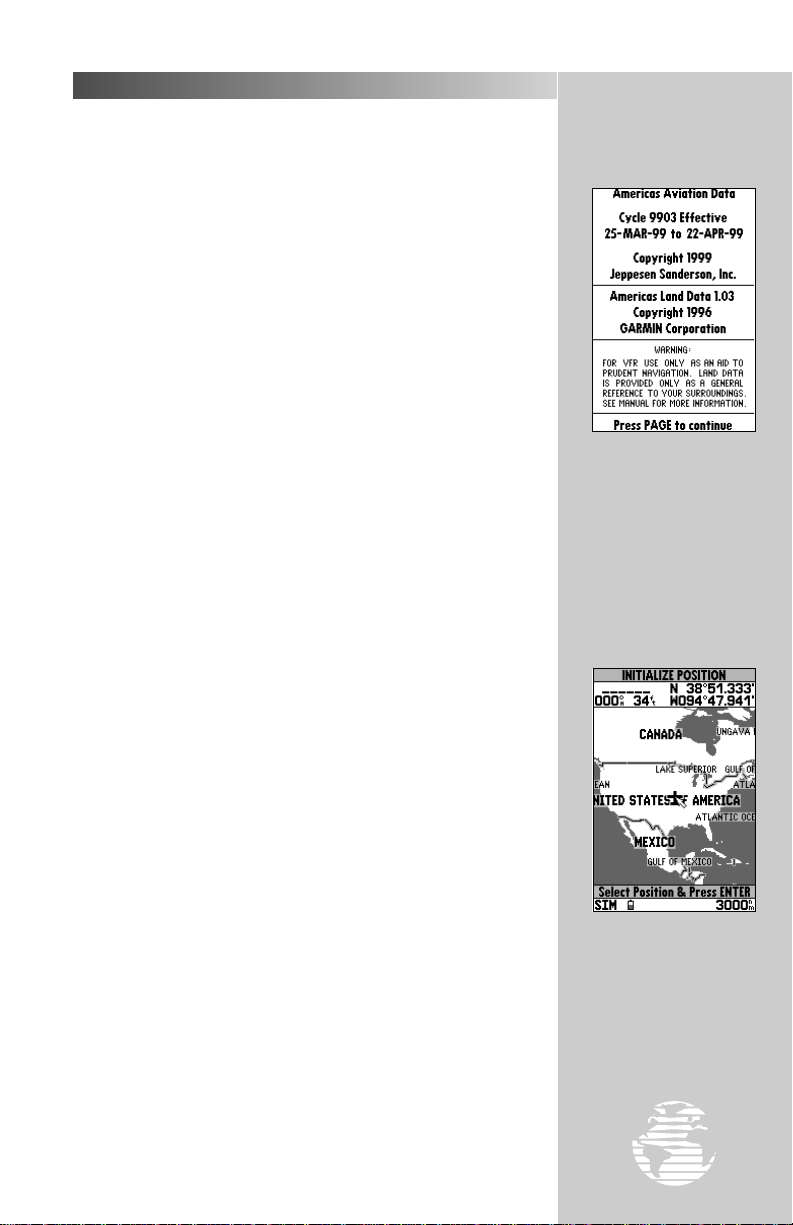
The welcome page will appear while the unit conducts a self test.
Once the internal test is complete, the aviator’s warning will appear,
asking you to read and acknowledge important information regarding
the proper use of electronic charts. The aviator’s warning also
displays the effective date of the internal Jeppesen NavData®.
To acknowledge the aviator’s warning:
1. Press the
A message alert and prompt will now appear to ask you to select an
initialization method.
To view a system message:
1. Press the
2. Press the
The select initialization window will appear, with the ‘select from
map’ option highlighted.
J
J
J
key until the power tone sounds.
P
key.
key.
key again to return to the previous page.
The aviator’s warning
indicates the effective date
of the Jeppesen database.
This warning is also a
reminder that electronic
charts should always be
double-checked for accuracy against your current
paper charts.
To initialize your present position graphically:
1. Press
The map page will appear, prompting you to select your approximate
present position with the map cursor.
2. Use the
your present position. If you have difficulty identifying your approximate position, use the down arrow of the
lower map scale.
3. Press
to initialize the receiver from the built-in worldwide map.
T
keypad to move the map cursor to a location close to
R
key to zoom in to a
A
to confirm your selection.
T
The initialization window offers several options to
speed the process of obtaining your first position fix.
Choose ‘Select from Map’ to
designate your approximate
position from the map page.
13
Page 16
TAKEOFF TOUR
INITIALIZING THE RECEIVER (cont.)
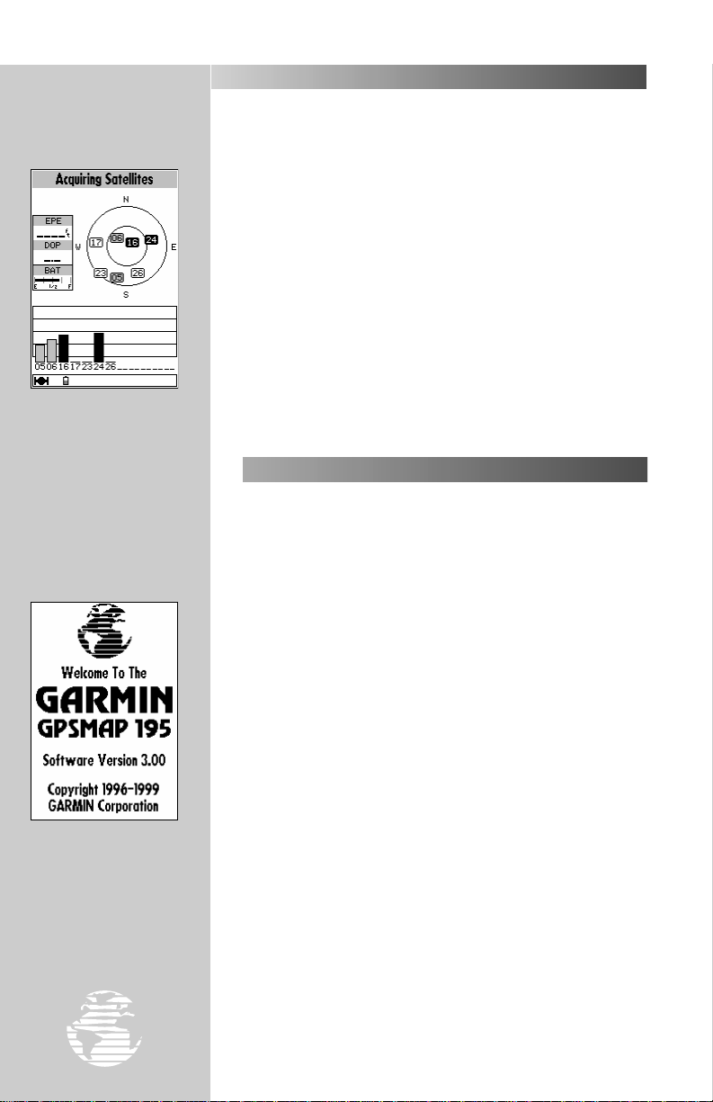
The GPSMAP 195 will now begin searching for the
appropriate satellites at your present position and should acquire a fix
within a minute or so. While the receiver searches for satellites, a
flashing satellite icon will appear at the left-hand side of the status
bar. A signal strength bar will also appear for each satellite received,
with the appropriate satellite number under each bar . The pr ogress of
satellite acquisition is shown in three stages:
• No signal strength bars— the receiver is looking for the satellites
indicated.
• Hollow signal strength bars— the receiver has found the
indicated satellite(s) and is collecting data.
• Solid signal strength bars— the receiver has collected the
necessary data and the satellite(s) is ready for use.
Hollow signal strength
bars will appear on the status page while the receiver
collects satellite data. Once
the data is collected and the
satellite is ready to use, the
signal strength bar changes
to solid.
When the GPSMAP 195
is turned on a welcome
screen appears briefly while
the receiver conducts an
internal self test. The same
key is used to turn the
PP
receiver on or off.
14
Once the receiver has collected information from at least three
satellites, the flashing satellite icon on the status bar will remain on
steadily, and the GPSMAP 195 is ready for use.
TURNING THE GPSMAP 195 ON & OFF
The GARMIN GPSMAP 195 is a powerful electronic charting/
navigating system that provides detailed chart coverage and
convenient control of many advanced features right from the moving
map display. The tour is designed to take you through the basic
pages and functions of the system, first by demonstrating the normal
process of obtaining a position fix, and then by using the simulator
mode. Once you’re familiar with the main pages and functions of the
unit, refer to the reference section for instructions on performing specific tasks and functions.
The Takeoff Tour assumes that the receiver has been properly
installed and initialized, and you have not changed any of the default
unit settings. If you have changed any settings (position formats,
units of measure, etc.), the descriptions and pictures in the tour may
not match your configuration.
Now that you’ve initialized the receiver and obtained a position fix,
let’s look at the normal power on sequence and see how it differs
without the initialization steps. For starters, we’ll need to turn the
GPSMAP 195 off for a moment.
To turn the GPSMAP 195 off:
1. Press and hold the
screen is blank.
Now we can turn the receiver back on again.
To turn the GPSMAP 195 on:
1. Press and hold the
welcome page will appear while the unit conducts a self test.
2. Once the self test is complete, press the
the aviator’s warning.
key for approximately one second, until the
P
key until the power tone sounds. The
P
key to acknowledge
J
Page 17
TAKEOFF TOUR
TURNING THE GPSMAP 195 ON & OFF (cont.)
The satellite status page will appear, and the receiver will begin
to acquire satellites. Notice that when the GPSMAP 195 is properly
initialized, the page sequence is shorter—the select initialization
window no longer appears. The time to obtain a position fix is also
much quicker.
ADJUSTING CONTRAST/BACKLIGHTING
From the satellite status page, you may quickly adjust the screen
contrast.
To adjust the screen contrast:
1. Increase the screen contrast by pressing the right arrow of the
keypad.
2. Decrease the screen contrast by pressing the left arrow of the
keypad.
3. Press the
The GPSMAP 195’s three-level screen backlighting is controlled
with the
P
When backlighting is on, a bulb icon will appear on the status bar.
To turn on and adjust the backlighting:
1. Press the
level (off, low, medium, or high).
key to finish.
T
key, and may be adjusted at any time from any page.
repeatedly until the backlighting is at the desired
P
R
R
The screen contrast may be
adjusted from the status page
by pressing the left/right arrows
on the RRKEYPAD. Press
to confirm changes.
††
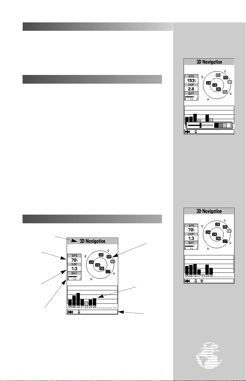
SATELLITE STATUS PAGE
Status Field
Satellite
Horizontal
Accuracy
Dilution of
Precision
Battery Level
Indicator
The GPSMAP 195’s satellite status page provides a visual
reference of satellite acquisition and receiver status, with a signal
strength bar graph and a satellite sky view in the center of the page.
The accuracy of your position reading is indicated on the upper left
hand side of the page.
Sky View
Signal Strength
Indicators
Status Bar
Whenever the screen
backlighting is on, a bulb icon
will appear on the status bar at
the bottom of every GPSMAP
195 page.
15
Page 18
TAKEOFF TOUR
The signal strength bars
indicate how strong the signal is from each satellite
being received. Taller bars
indicate stronger signals.
SATELLITE STATUS PAGE (cont.)
The satellite sky view and signal strength bars give you an
indication of what satellites are visible to the receiver and whether
they are being tracked. Satellites, numbered from 01 through 32, are
placed on the page indicating their position in the sky. The
signal strength bars indicate how strong the signal is from each
satellite being tracked— the taller the bar, the stronger the signal.
(For more information on the satellite status page, turn to page 46.)
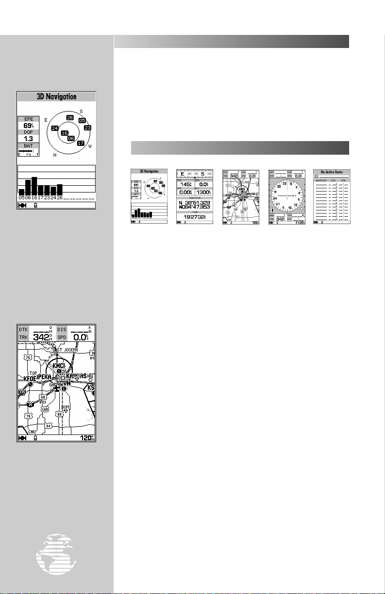
PAGE SEQUENCE
J RRR LLL Q
The satellite status page is one of five main pages displayed on your
GPSMAP 195. All five pages are linked together in a simple chain,
which allows you to scroll through the pages in either
direction using the
move on to the next page, the position page.
or Qkeys. To continue the tour, let’s
J
During normal use the
GPSMAP 195 will automatically sequence to the
map page once enough
satellites are received to
compute a position fix.
16
To scroll to the next page in sequence:
1. Press the
to sequence in reverse order until the position page appears.)
Q
key until the position page is displayed. (Or press
J
?
#
NOTE: During normal use the GPSMAP 195 will automatically sequence
to the map page once enough satellites are received to compute a position fix.
If any keys are pressed during the process of acquiring satellites, it will cancel
this automatic sequence.
Page 19
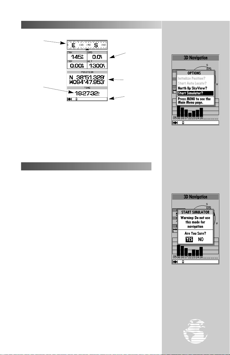
POSITION PAGE
Graphic
Compass
Time
of Day
The GPSMAP 195’s position page shows where you are, what
direction you’re heading and how fast you’re going. The compass at
the top of the page indicates your current ground track (or direction
of travel) while you’re moving. The four user-selectable data fields
below the compass show your current ground track and ground
speed, along with a resettable trip odometer and altitude display
(default settings). Your current latitude and longitude, along with a
12/24-hour clock, appear at the bottom of the page.
SELECTING SIMULATOR MODE
To continue the takeoff tour and explore the rest of the main pages,
you’ll need to put the GPSMAP 195 in simulator mode.
Data
Fields
Position
Coordinates
Status Bar
TAKEOFF TOUR
To place the GPSMAP
195 in simulator mode,
press
lite status page and select
‘Start Simulator?’.
from the satel-
øø
To place the GPSMAP 195 in simulator mode:
1. Press the
page is displayed.
2. Press the
of options and functions for the status page.
3. Use the UP or DOWN arrow of the
Simulator?’ option and press
4. Press the
or Qkey (repeatedly) until the satellite status
J
key. The options page will appear, displaying a menu
O
keypad to highlight the ‘Start
R
.
T
key to confirm the simulator warning.
T
!
WARNING: Keep in mind that the GPSMAP 195 does not track satellites
in simulator mode and should never be used for actual navigation. (The
GPSMAP 195 cannot turn on in simulator mode. If you forget to change back
to normal operation before shutting the receiver off, the next time you use the
receiver it will return to normal operation mode.)
Once the simulator has been started, the status field at the top of
the page will display a ‘Simulating Navigation’ status. Since the
GPSMAP 195 doesn’t receive satellite signals in simulator mode, you
don’t need to be outside anymore. This is a good time to settle into
a comfortable chair, at home or in the office, and continue the rest of
the Takeoff Tour.
#
To start the simulator,
confirm the simulator
warning by pressing
Remember, simulator mode
should never be used for
actual navigation!
††
.
17
Page 20
TAKEOFF TOUR
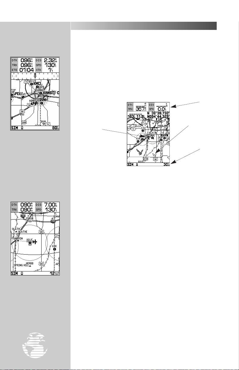
MAP PAGE
The next main page is the map page. To continue the Takeoff
Tour, let’s select this screen now.
To select the map page:
1. Press
The GPSMAP 195’s map page combines digital charts with a userselectable display of navigation data and a built-in Jeppesen database.
Before we take off on our practice flight, let’s take a brief look at its
various features.
or Q(repeatedly) until the map page appears.
J
Data
Window
The map page can also
be configured to display
additional data fields and a
graphic course deviation
indicator (CDI) or ground
track compass.
Use the
zoom in or out, displaying
the desired level of detail.
AA
key to
Aircraft
Icon
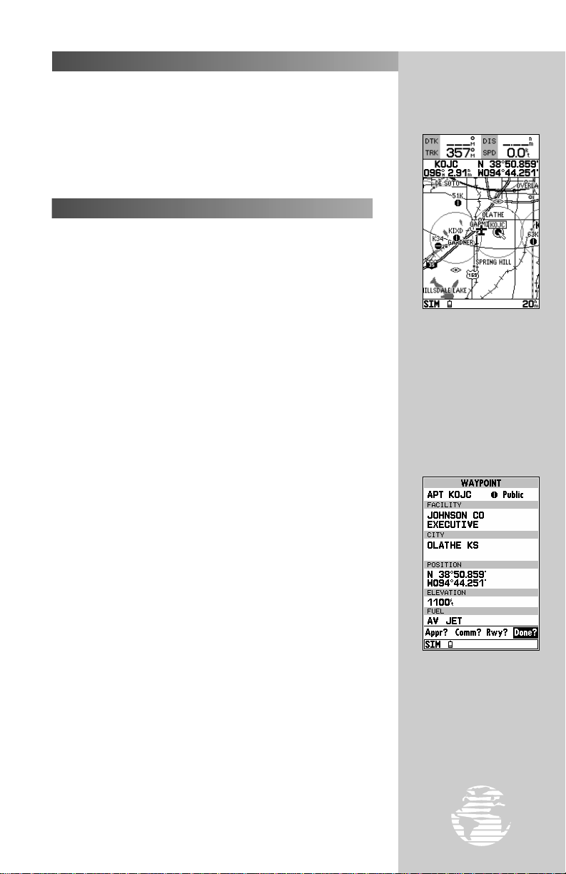
The map display, located in the middle of the page, shows your
aircraft as an airplane icon on an electronically-generated chart,
which includes airports, VORs, NDBs, intersections and airspaces.
The map display on your GPSMAP 195 should show the local area
around your present position. An internal base map adds geographic names, lakes, rivers, coastlines, interstate highways, U.S. highways
and state highways. It also displays your track, routes and nearby
waypoints. An on-screen cursor lets you pan to other map areas,
determine the range and bearing to a position, and perform various
waypoint and route functions. Note the on-screen cursor—as well as
bearing, distance and position information—in the example above.
The data window, located at the top of the page, provides a user-
selectable display of various navigation data, including ground track,
ground speed, and the bearing and distance to the cursor (when panning) or a particular waypoint.
The status bar, located at the bottom of the page, displays the
current map scale setting. The scale setting represents the distance
from the left side of the map display to the right side. To get a
better view of your current surroundings, zoom in or out to provide
the level of detail you desire.
Cursor
Map
Scale
18
To zoom in or out on the map page:
1. Press the down arrow on the
detail for a smaller area.
2. Press the up arrow on the
detail for a larger area.
key to zoom in and display more
A
key to zoom out and display less
A
Page 21
TAKEOFF TOUR
MAP PAGE (cont.)
The built-in base map provides geographic detail at scales down to
1/10 nautical mile. The built-in basemap is designed for best performance at scales down to 20 nautical miles. Keep in mind that whenever you do exceed the usable range of the base map (or a mapping
datacard) the range field will display ‘OVR ZM’ to indicate that you
should exercise caution when using the cartographic data. See page
53 for more information on map scales.
USING THE MAP CURSOR
W orking fr om the map page is a simple pr ocess that centers ar ound
the use of the cursor. Controlled by the
important tool that can be used to pan to other map locations, create
waypoints, edit routes, and review database information for
on-screen airports and navaids.
To get a feel for using the map page and using the cursor, try the
following exercise:
1. Use the
nm setting. The airplane icon should be centered on the map.
2. Using the
near your position. Notice how another data field appears at the
top of the page, showing the bearing and distance from your
aircraft to the cursor, along with the lat/long position of the cursor.
3. Using the Rkeypad, move the cursor to one of the airport icons
appearing on the map display, then press
location page appears showing the database information for that
airport. Press
4. Press the
aircraft on the map display.
key’s DOWN arrow to set the map scale to the 50
A
keypad to move the cursor, try following a highway
R
to return to the map display.
Q
key to remove the cursor and recenter your
Q
keypad, the cursor is an
R
. The airport
T
To select an on-screen
airport, navaid or waypoint; simply move the
cursor over the desired
waypoint. The name and
position, along with the
bearing and distance to that
point, from present position,
will appear.
?
NOTE: As you pan the map display, moving the cursor to a new area, the
GPSMAP 195 must load additional map data before it can be displayed. Short
delays in map redrawing may occur when panning beyond the current area.
The cursor can also be used to select a GOTO destination right
from the map page. With the cursor over a given point on the screen
— even without an icon at that point — you can designate that point
as a GOTO destination by simply pressing the
is not demonstrated in this takeoff tour, but may prove handy on
many occasions. It’s described in more detail on page 52.)
As you become more familiar with the panning cursor, you’ll find
this feature particularly useful—letting you explore areas around the
world, review waypoints, create routes, and view airspace information. Wherever you move the cursor, you’ll always be just one
keystroke away from returning the map to your present position.
#
key. (This feature
G
Q
By selecting an on-screen
airport, navaid or airspace
and pressing
view the database information for that waypoint.
††
, you can
19
Page 22
TAKEOFF TOUR
To display the nine nearest airports, press the
key. If the nearest list shows
navaids, airspaces, etc.;
press
˜˜
to the nearest airport list.
˜˜
again to return
NEAREST WAYPOINTS PAGE
Now that you have a feel for how the cursor works, it’s time to
move on and see how the GPSMAP 195 would look in the air. To help
you practice using the map page and other features, let’s use the
GOTO function to fly to an airport stored in the receiver’s memory.
From this, you’ll learn what to expect when you’re out flying with
your new GPS receiver.
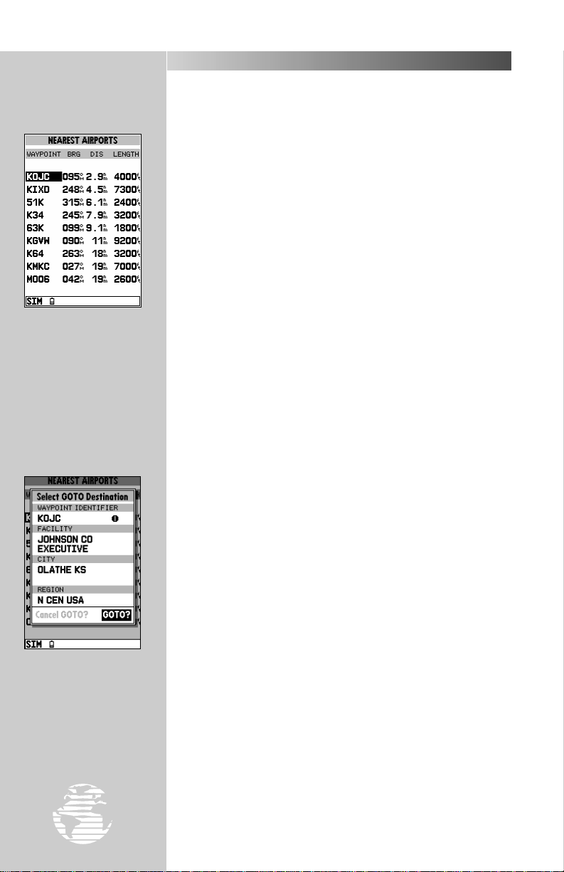
Suppose you experienced an emergency during your trip and needed to find a place to land. Better yet, you just want to stop for a break
at a nearby airport or top off the tanks. A list of the nine nearest airports within 200 miles of your present position is just a keystroke
away! Instantly, you can select an airport from the list and designate
it as your destination waypoint. Or, you can review all the available
Jeppesen data for that particular airport. Let’s take a look at the closest airports in your area.
To view the nine nearest airports:
1. Press the
A list of the nine nearest airports appears, along with the bearing
and distance to each one.
key to display the nearest waypoints page.
N
?
NOTE: If for any reason the near est waypoints page does not show airports,
but instead lists nearest airspaces (which we’ll cover in just a moment), VORs,
NDBs, intersections or user waypoints; just press the
to return to the nearest airport list.
#
key a second time
N
By pressing the ©©key,
followed by
lighted airport instantly
becomes your destination
waypoint.
††
, the high-
20
To GOTO a nearest airport:
1. Use the UP or DOWN arrows on the
desired airport.
2. Press the
your destination waypoint.
Now you can use the map or navigation pages to guide you to your
destination airport. Oftentimes, you may want more information
about an airport, like how long the runways are or if fuel is available.
From the nearest waypoints page you can review the Jeppesen data
for any listed airport or navaid, using the waypoint definition page(s).
To view the Jeppesen data for a nearest airport:
1. Use the UP or DOWN arrows on the
desired airport.
2. Press the
airport.
key, followed by T, to designate the airport as
G
key to view the waypoint definition page(s) for that
T
keypad to highlight the
R
keypad to highlight the
R
Page 23
TAKEOFF TOUR
USING THE GOTO KEY
GPS is all about using positions called waypoints and navigating
to them using the receiver’s navigation guidance and map displays.
Now that you’ve seen how the status page can be used to monitor
satellite acquisition and the position and map pages can be used to
observe your present position, it’s time to explore the navigation features of the GPSMAP 195— starting with the GOTO function. The
key, located on the left side of the keypad below the Pkey,
G
is the primary tool used to select a destination waypoint or a route to
navigate. The
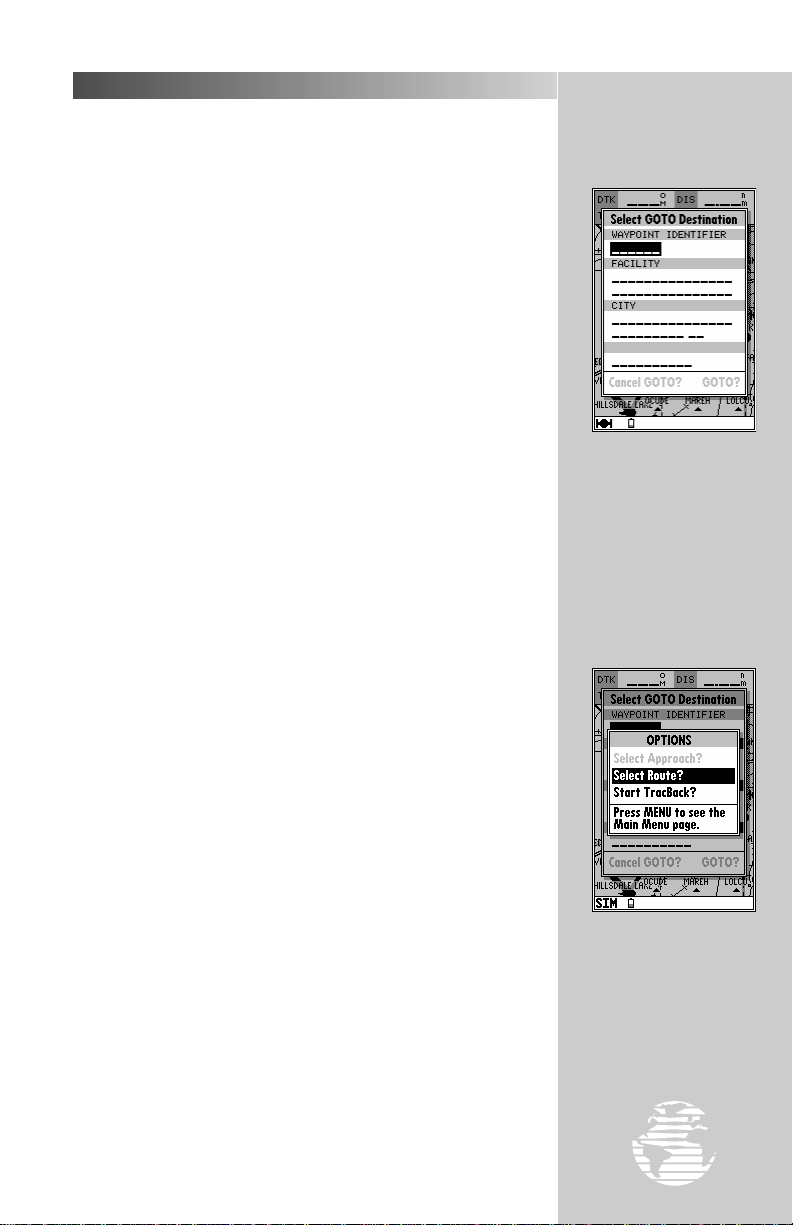
• Pressing
may select any airport or navaid in the database, or any user waypoint in memory. When the destination is an airport, it may be
selected by identifier, facility name or city.
key can be used in three main ways:
G
once displays a GOTO window from which you
G
• Pressing
options that lets you start a TracBack™ route, select a published
approach for an airport, or select a stored route to navigate.
• After panning to a location on the map display, pressing
allows you to graphically select an on-screen waypoint, navaid or
cursor position as your destination.
For this simulated trip, we will select a nearby airport and fly
directly to that location. If you don’t recall the identifiers of any nearby airports, return to the nearest airports page discussed on the preceding page and select your destination directly from the list (by
highlighting the desired waypoint first, then pressing
Otherwise, we’ll enter the identifier using the keypad.
To select the destination airport:
1. Press
2. Highlight the waypoint identifier field by pressing the DOWN arrow
on the
3. Press
4. Use the UP and DOWN arrow on the
character of the airport identifier.
5. Use the RIGHT arrow of the
ter. (If you make a mistake, back up with the LEFT arrow.)
6. Repeat steps 4 and 5 until the airport identifier has been selected.
7. Press
should now indicate the bearing and distance to the selected
airport.
followed by the Okey provides a list of GOTO
G
G
G
. The GOTO window will appear.
G
keypad.
R
to begin entering the airport identifier.
T
keypad to enter the first
R
keypad to move to the next charac-
R
to accept the selected airport. The top of the map page
T
).
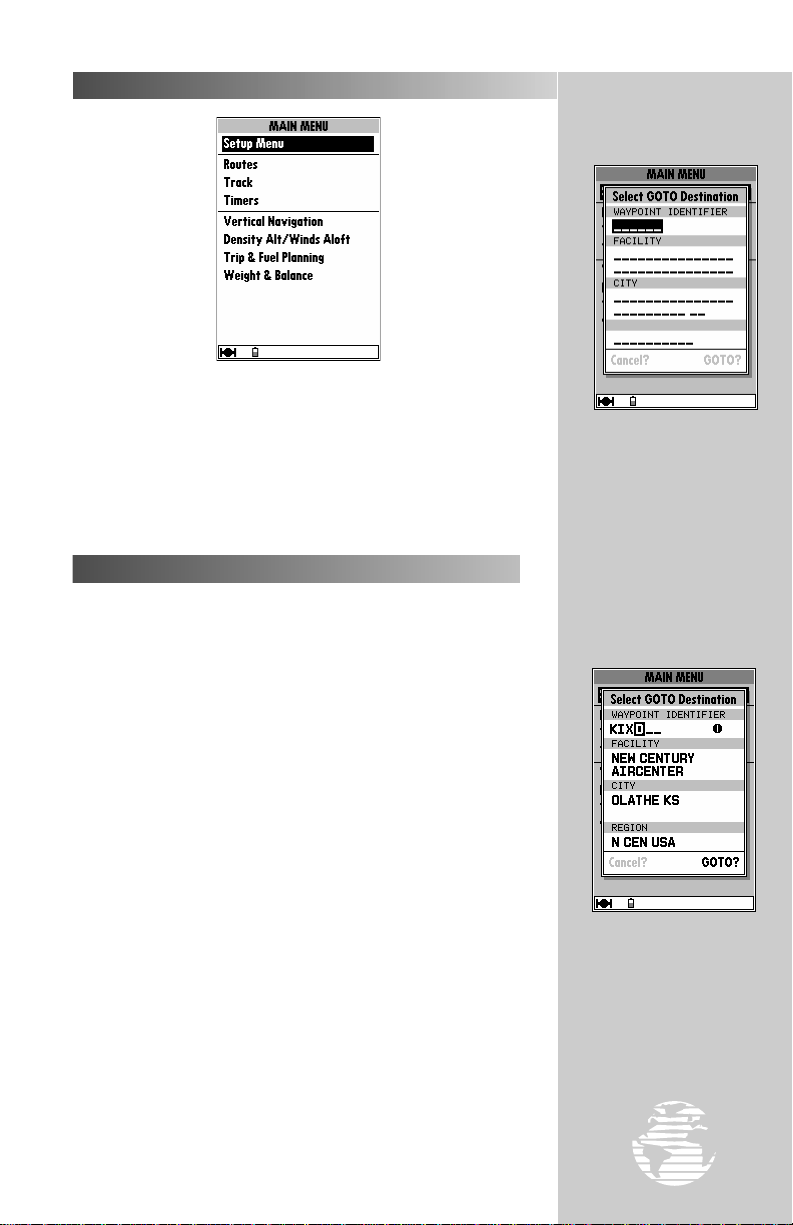
Pressing
the GOTO window, from
which you may select any
airport or navaid in the
Jeppesen database, or any
user waypoint you’ve
entered in memory.
The GOTO options page
lets you start a TracBack™
route or activate a stored
route to navigate.
©©
displays
21
Page 24
TAKEOFF TOUR
HSI PAGE
The next screen following the map page is the HSI (Horizontal
Situation Indicator) page.
To select the HSI page:
1. Press the
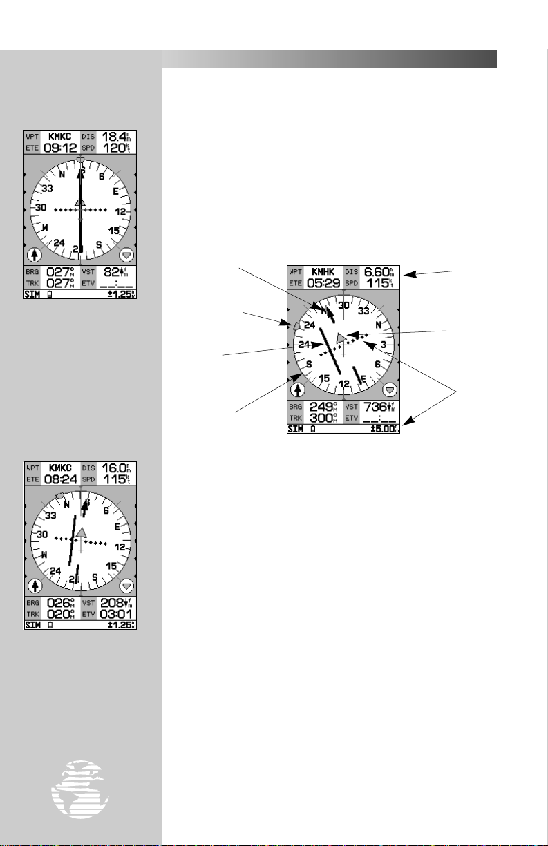
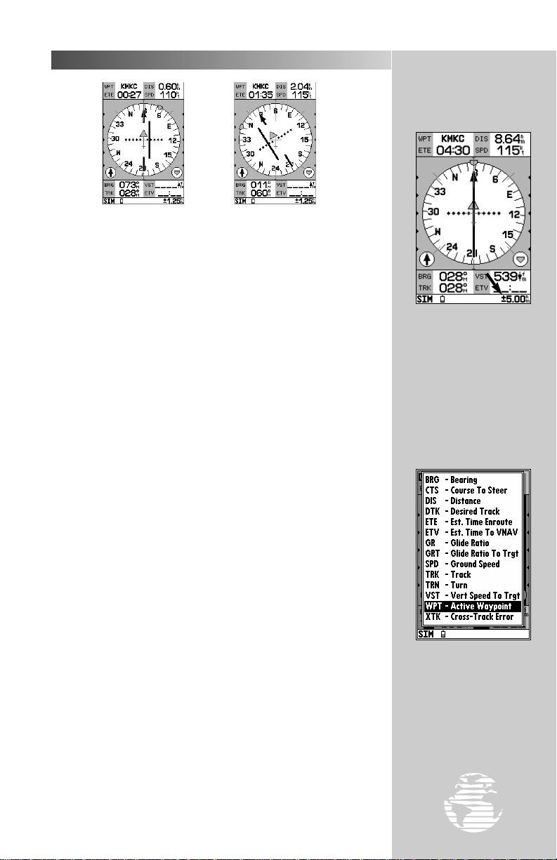
The HSI page is your primary navigation screen and graphically
depicts desired track, ground track, crosstrack error (course
deviation) and a TO/FROM indication. The HSI display also provides
vertical guidance when using the unit’s vertical navigation features.
key (repeatedly, if necessary, until it appears).
J
The HSI page graphically
depicts desired track,
ground track, course deviation and TO/FROM. The
example shown above is on
course and heading toward
the destination waypoint.
Use the RRkeypad to
‘drive’ simulator mode
operations. The UP/
DOWN arrows control
speed. The RIGHT/LEFT
arrows control ground
track.
Desired Track
Pointer
Bug Indicator
D-Bar
(part of CDI)
Compass
Card
User-selectable data fields appear at the top and bottom of the
page, and provide distance to destination waypoint, ground speed
and estimated time en route, among others.
Whenever the GPSMAP 195 is in simulator mode, you can adjust
your speed and course from the HSI page using the
let’s head toward our airport by adjusting the ground speed and track
to get a feel for how the HSI works.
To adjust the simulated aircraft ground speed:
1. Press the UP arrow of the
5-knot increments. Press the DOWN arrow to decrease the
speed in the same increments.
To control the ground track:
1. Press the LEFT or RIGHT arrows of the
To reset the simulator to automatically track the desired course:
1. Press
, followed by T.
G
keypad to increase the speed in
R
keypad.
R
Data
Fields
TO/FROM
Flag
CDI
Scale
keypad. Now
R
22
Page 25
HSI PAGE (cont.)
TAKEOFF TOUR
Off course to the Left
Notice that as you get off course, the compass card, desired track
pointer and D-bar move to give you graphic guidance to get back on
course. The compass card rotates to indicate your current ground
track at the top of the page. (Don’t confuse this with aircraft
heading because it may be different!) The desired track pointer stays
fixed on the desired track (DTK) to your destination waypoint— the
original course line from point of origin to destination waypoint. The
D-bar and CDI (course deviation indicator) show just how far left or
right of the desired course you have drifted.
The scale setting for the CDI is shown at the bottom right of the
page. The scale setting represents the distance from the center of the
CDI to full left or right limits. The default CDI setting is 1.25 nm, but
can also be set for 0.25 or 5.0 nm ranges.
To change the CDI scale:
1. Press the
decrease the scale).
The HSI page data fields may also be configured to display any of
fourteen different navigation values. These navigation values are
defined in Appendix F. To demonstrate how data fields are changed,
let’s change the ETE (estimated time en route) data field so it displays
DTK (desired track).
To change a data field:
1. Press the
2. Highlight the ‘Change Data Fields?’ option and press
highlight will now appear in the top-left data field (starting with the
WPT field).
3. Use the
4. Highlight the ‘DTK’ option and press
5. Press
press
T
at right).
Q
R
key in either direction (up to increase, down to
A
key to display the HSI page options.
O
keypad to move the field highlight to the ETE field and
. A list of available data items will appear (see illustration
to finish.
Off course to the Right
. The field
T
.
T
The scale setting for the
CDI is shown on the status
bar. Use the
change the scale.
The data fields may be
configured to display any of
fourteen different values.
To change a data field,
select the HSI options page
by pressing
AA
øø
key to
.
23
Page 26
TAKEOFF TOUR
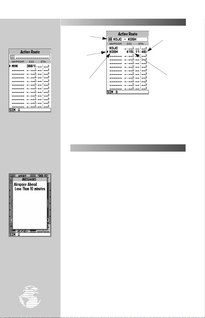
ACTIVE ROUTE PAGE
When using the
key, the active route page
shows the destination
waypoint name, distance
from present position and
estimated time of arrival.
©©
Route # and
Description
Current
Destination
Destination
Waypoint
Name
The last of the five main pages is the active route page. The active
route page shows the GOTO waypoint or each waypoint of a route,
with waypoint name, cumulative distance and ETA fr om your present
position. The current destination waypoint is marked with an arrow
on the left-hand side of the page. If no destination has been specified
using the
As you continue along your route, you may pass in close
proximity to, or enter, an airspace. Whenever you are within 2 nm,
projected to enter, or inside an airspace, the GPSMAP 195 will notify
you with a message and supply detailed information on each airspace
you are being alerted to. Look closely at the map display. If you see
an airspace ahead of your current route of flight, you may be alerted
with a message as you approach it. (You may have to wait a few minutes to get this message, depending on how fast you are going.)
key or a route, no waypoints will be listed on the page.
G
AIRSPACE WARNINGS
Estimated Time
of Arrival
Distance to
Waypoint
When an airspace warning occurs, your first indication will be an audible
tone and ‘Message - Press
Page’ flashing on the status
bar. To view the airspace
alert message, press
∆∆
.
24
?
NOTE: The airspace alert occurs when your current altitude places you
within the floor and ceiling limits of the airspace. If you are several hundred
feet, or more, below or above these limits, the GPSMAP 195 will not bother you
with an alert, but the airspace boundary will still appear on the map display.
To return to the map display and view the airspace boundaries:
1. Press the
appears.
J
#
or
key several times until the map page
Q
Page 27
AIRSPACE WARNINGS (cont.)
When the airspace warning occurs the GPSMAP 195 will beep
several times and ‘Message-Press Page’ will flash on the status bar at
the bottom of the screen.
To view the airspace message:
1. Press the
2. Press
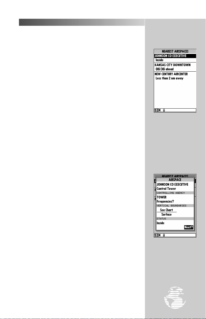
Additional information, including name, class, controlling agency
and altitudes, is also available for each airspace you are alerted to.
To view the additional airspace information:
1. Press the
information for up to 6 airspaces you are being warned about. Each
listing will display the type of warning and your time to intrusion, if
applicable.
2. To view specific information on any listed airspace, highlight the
desired airspace name using the
airspace definition page appears, providing additional information
including floor and ceiling limits for the selected airspace.
3. To return to the nearest airspace page, press the
4. To return to the previous page (the map page), press
key.
J
again to return to the map page.
J
key. The nearest airspace page will appear, listing
N
R
keypad and press T. The
key.
Q
.
Q
TAKEOFF TOUR
A list of any airspace
alerts is available from the
nearest airspace page,
which also shows the type of
warning and time to entry
(if applicable).
?
NOTE: When an airspace alert is provided, expect the
to the nearest airspacepage— not the nearest airport list. However, there may
be rare instances when an airspace alert is provided and pressing
provides a list of airports or navaids instead. This simply means the alert
condition no longer exists. During maneuvers or heading changes, your course
may momentarily be projected into an airspace creating a temporary alert
condition.
Airspace alert messages for class B, class C, MOA, restricted and
other areas may be turned off to avoid nuisance alerts, and may also
be removed from the map display to avoid excess clutter at higher
map scales. For complete information and definitions on airspaces,
see page 67-68.
#
key to default
N
N
The airspace definition
page provides even more
detail regarding an airspace
alert. Consult this page to
find the floor and ceiling
limits, controlling agency
and frequency.
25
Page 28
TAKEOFF TOUR
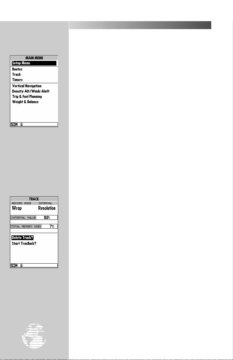
The main menu page is
used to select the setup,
route, track and E6B features of the GPSMAP 195.
To display the main menu
page, press
øø
twice.
MAIN MENU PAGE
As you’ve seen, the GPSMAP 195’s main pages provide vital status,
position, navigation and map information. The last page we’ll cover
in the tour is the main menu page, which provides access to the
GPSMAP 195’s route and planning functions, as well as various operation and navigation setup features. The main menu is available from
any page, and is accessed through the
To access the main menu page:
1. Press the
The main menu page’s 8 submenus are divided into categories by
function. You can select a particular submenu by simply highlighting
the desired option with the
for how the main menu page works, let’s clear out the track log
created during the simulated tour. This will ensure that you have a
clean slate once you start navigating on your own.
To select the track submenu:
1. Highlight the ‘Track’ menu option with the
.
T
The track log page allows you to specify whether to record a track
log and define how it is recorded. A track log is a record of position
samples showing where you have been. This information can be
automatically stored by the GPSMAP 195 and displayed on the map,
leaving a trail behind you as your flight progresses. The track log
page also provides both an indicator of the total track memory used
and the individual functions to clear the track log or start a TracBack
route. (A TracBack route allows you to retrace your flight, following
the track log information back to where you started. See page 81 for
more information on this feature.)
O
key twice.
R
key and pressing T. To get a feel
O
key.
keypad and press
R
To delete the track log
select the ‘Delete Track?’
option and press
††
.
26
To delete the track log:
1. Highlight the ‘Delete Track’ option and press
page will appear.
2. Highlight the ‘Yes’ prompt and press
3. Press
Congratulations! You’ve now gone through the basic operation of
the GARMIN GPSMAP 195. Y our new receiver is a powerful tool with
many advanced features not covered in this takeoff tour. For detailed
instructions on using these features or performing a specific task,
please refer to the quick reference guide or the appropriate reference
section of this manual.
to return to the main page sequence.
J
T
. A confirmation
T
to confirm.
Page 29
WAYPOINT CATEGORIES
The GPSMAP 195 uses an internal Jeppesen database to provide
position and facility information for thousands of airports, VORs,
NDBs and intersections. Each facility in the database is stored as a
waypoint, with its own latitude/longitude, identifier (up to six letters
and/or numbers) and other pertinent information. Up to 250 user
waypoints and 250 symbol waypoints may also be created and stored
in memory.
REFERENCE
WW
KEY
Waypoint information is available through the GPSMAP 195’s
key. Waypoints are divided into five categories for your convenience.
Each category provides different types of detailed information for a
selected facility:
• Airports— Identifier, city/state, country, facility name, position
(lat/lon), elevation, fuel services, runways, approaches and
communications frequencies.
• VORs— Identifier, city/state, country, facility name, position
(lat/lon), frequency and co-located DME or TACAN availability.
• NDBs— Identifier, city/state, country, facility name, position
(lat/lon) and frequency.
• Intersections— Identifier, region/country, position (lat/lon)
and range/bearing to nearest VOR.
• User— Identifier (name), position (lat/lon), user comments and
reference waypoint.
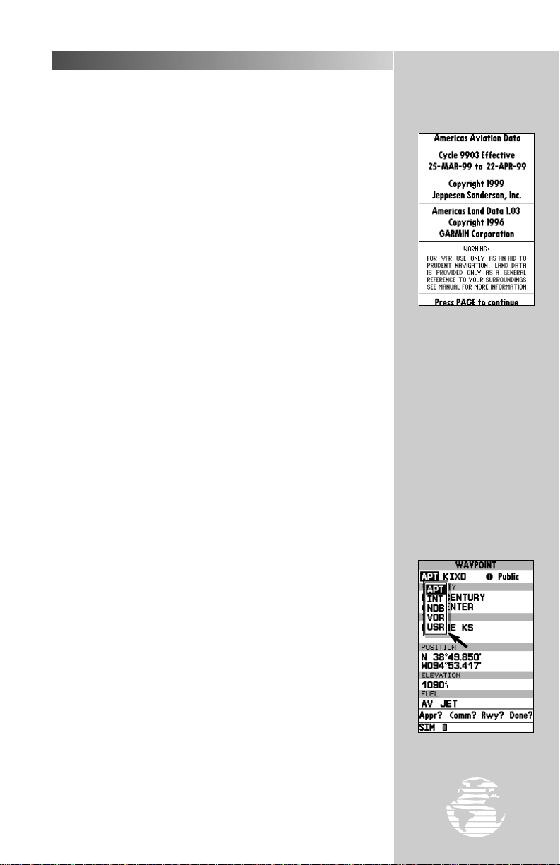
T o view the waypoint information for a desir ed waypoint, select the
waypoint category from the category field, located at the top left of
the waypoint page.
To choose a waypoint category:
1. Press
2. Highlight the waypoint category field using the
3. Press
all five category types will appear.
4. Use the UP or DOWN arrows to select the desired category.
5. Press
After a waypoint category is selected, information for a waypoint
can be viewed by entering the identifier or name of the desired
waypoint. Airports, VORs, and NDBs may be retreived by either the
identifier, facility name, or the location (city). Intersections and user
waypoints must be selected by the identifier.
to display the waypoint definition page.
W
keypad.
R
to begin selection of the waypoint category. A listing of
T
to confirm the category selection.
T
W
The GPSMAP 195 is
available in three database
versions: Americas covers
North, Central and South
America. Atlantic Inter-
national covers Europe,
Africa, Middle East and
northern Asia. Pacific
International covers Asia,
Australia, Middle East and
Eastern Europe. The database cycle is displayed with
the aviator’s warning. A
database update can be
ordered from your dealer or
directly from GARMIN.
Waypoint Categories
27
Page 30
REFERENCE
WW
KEY
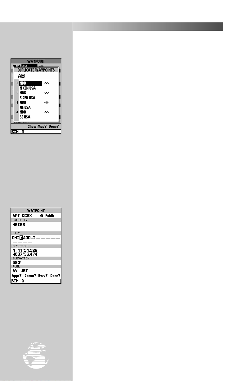
Waypoints are selected
by their identifier (or
name). If more than one
waypoint uses the same
identifier, the duplicate
waypoint page will be displayed, allowing you to
choose the correct waypoint
VIEWING WAYPOINT INFORMATION
To enter a waypoint identifier:
1. Use the
2. Press
3. Use the UP and DOWN arrows to spell out the desired identifier,
using the RIGHT arrow to move to the next character position.
4. As the identifier is entered, the GPSMAP 195’s Spell’N’Find feature
will scroll through the available database, displaying any waypoints
with the same identifier letters you have entered to that point. When
the desired waypoint is displayed, press
keypad to highlight the identifier field.
R
.
T
T
.
?
The GPSMAP 195 uses ICAO (International Civil Aviation Organ-
NOTE:
ization) identifiers to designate airports. In the contiguous United States, the
prefix letter for airports is ‘K’. This applies to airport identifiers that are letters
only. For example, ‘LAX’ becomes ‘KLAX’ and ‘JFK’ becomes ‘KJFK’. Airport
identifiers that use numbers, such as ‘H34’ or ‘7M5’, do not use the ‘K’ prefix.
Some waypoints in the database may have the same identifier.
When you have entered a waypoint name that is not unique, the
duplicate waypoint page will be displayed for you to select the
desired waypoint. A list showing each duplicate by waypoint
category and region makes it easy to identify the correct one.
#
Besides using waypoint
identifiers; airports, VORs
and NDBs may be selected
by facility name or city.
28
To select the desired waypoint from a list of duplicates:
1. With the duplicate waypoint page displayed, highlight the desired
waypoint and press
Once you’ve selected a waypoint category, waypoint information
for airports, VORs or NDBs may be retrieved by entering the facility
name or the city name. (Intersections and user waypoints cannot be
retrieved by facility or city name.)
To select a waypoint by facility or city name:
1. Select the desired waypoint category (Airport, VOR or NDB).
2.
Use theRkeypad to highlight the facility name or city name field. If
the facility and city name fields do not appear on the current airport
page, you must select the airport location page first. Refer to the following page for information on scrolling through airport pages.
3. Press Tto begin entry of the facility or city name.
4.
Enter the name of the facility or city with theRkeypad. The
GPSMAP 195’s Spell’N’Find feature will scroll through the
database, displaying any waypoints with the same letters you have
entered to that point. In some instances there may be more than one
waypoint for the selected facility or city name. To view all waypoints
with the desired name, continue spelling the name with the
pad. Once the name appears on-screen, continue to press the
UP/DOWN portion of the
5. When the desired waypoint appears, press T.
.
T
keypad to view all entries for that name.
R
R
key-
Page 31

AIRPORT INFORMATION
The GPSMAP 195 features four airport pages:
• Airport location— allows entry of desired airport by identifier,
facility name or city; displays latitude, longitude, elevation; and
fuel availability.
• Airport communication— allows entry of desired airport by
identifier and displays radio frequencies/usage.
• Airport runway— allows entry of desired airport by identifier;
displays runway designations, length, surface and lighting
information, and/or pilot-controlled lighting frequencies.
• Airport approach— allows entry of desired airport by identifi-
er; displays final course segment of published ILS, localizer,
RNAV, GPS, VOR, VOR/DME or NDB approaches.
REFERENCE
WW
KEY
The airport runway page
shows runway data and a
map of the area around the
airport. To zoom in/out
and see more detail for the
airport area, use the
key.
AA
To scroll through the airport pages:
1. Select the airport category and enter the desired airport identifier.
The airport page initially displayed will be the same as the last
airport page viewed.
2. Use the LEFT arrow to move the field highlight to the ‘Loc?’, ‘Comm?’,
‘Rwy?’ or ‘Appr?’ prompt and press
prompts are available at any time. The fourth item is the screen
you’re currently viewing.)
To exit the airport pages and return to the previously viewed page:
1. Press the
Waypoint
Category
Airport
Identifier
Airport Position
Coordinates
Other Available
Airport Pages
Q
key.
. (Only three of these
T
Facility Name
City Location
Airport
Elevation
Available Fuels
To scroll through the various airport pages select
‘Loc?’, ‘Comm?’, ‘Rwy?’ or
‘Appr?’, as desired.
29
Page 32

REFERENCE
WW
KEY
The airport location page
shows the facility name,
city, position coordinates,
field elevation and available fuels for the selected
airport.
AIRPORT INFORMATION (cont.)
The GPSMAP 195’s airport location page displays the latitude,
longitude and elevation of the selected airport, as well as fuel
availability. From the airport location page, you can enter a desired
airport by identifier, facility name or city as described on page 28.
The following descriptions and abbreviations are used on the airport
location page:
Elevation— Field elevation in feet or meters
Position— Airport location in the position format you have
currently selected from the setup page (e.g.,
latitude/longitude or UTM/UPS)
Fuel— Lists the types of fuel available on the airport:
• AV— AVGAS: 80-87 octane, 100 LL, 100-130 octane
• JET— Jet A, Jet A-1 or Jet A+
• MO— MOGAS: 87 octane unleaded
Waypoint
Category
Airport
Identifier
Frequency
Scroll Bar
Use the RRkeypad to
scroll through the list of frequencies. As you progress
through the list, the scroll
bar on the right margin
shows which portion of the
list is currently being displayed.
30
Frequency
Type
The airport communication page displays radio frequencies and
their usage for the selected airport, and allows entry of a desired
airport by identifier only (see page 28). The following frequencies are
displayed if available:
• ATIS • Pre-Taxi
• Clearance • Ground
• Tower • Unicom
• Multicom • Other
• Departure • Approach
• Arrival • Class B
• TMA • CTA
• Class C • TRSA
Other Available
Airport Pages
Page 33
AIRPORT INFORMATION (cont.)
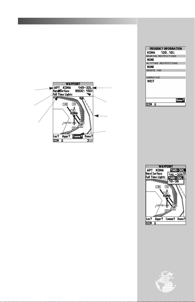
When a frequency type is followed by a question mark (‘?’),
restrictions apply to that frequency. Restrictions based on sector
and/or altitude may apply.
To view frequency restrictions:
1. Highlight the desired frequency type.
2. Press the
additional detail about the selected frequency.
key. The frequency information page appears with
T
REFERENCE
WW
KEY
Waypoint
Category
Airport
Identifier
Surface and
Lighting Conditions
The next airport page is the runway page, which features a diagram
of available runways, along with designations, length, width, surface
and lighting information for the selected airport.
The runway area map provides a north-up graphic of available
runways, with length, width, surface and lighting data listed below
the runway designation. The ‘Surface’ field will display one of the
following surface types: hard, turf, sealed, gravel, dirt, soft, unknown
or water. The ‘Lights’ field will indicate one of five lighting schemes:
part time, full time, pilot controlled (with frequency), no lighting or
unknown.
If the airport has more than one runway, additional runway data
can be viewed by selecting another runway from the runway designation field.
To view additional runway data:
1. Highlight the runway designation field.
2. Press the
3. Use the
4. Press
key.
T
keypad to select the desired runway.
R
to confirm the selection.
T
Runway
Designation
Runway Length
and Width
Runway Area
Map
Other Available
Airport Pages
Some frequencies have
usage restrictions, as denoted by the ‘?’ at the end of the
frequency type. By highlighting these frequency
types and pressing
the restriction information
will appear.
Data for each runway is
available from the runway
designation field. Highlight
this field and press
display a list of available
runways.
††
††
,
to
31
Page 34

REFERENCE
WW
KEY
Use the
zoom in or out to the
desired level of detail.
AA
key to
AIRPORT INFORMATION (cont.)
The runway page also allows you to zoom in, zoom out and pan
the screen to see the level of detail you desire. For larger airports you
may zoom out and/or pan around the runway area map to see
additional detail.
To zoom in or out on the runway page:
1. Press the UP arrow of the
setting will show a larger area, but in less detail.
2. Press the DOWN arrow of the
scale setting will show a smaller area, but in greater detail.
To pan the runway area map:
1. Highlight the runway area map using the
runway area map is highlighted the outline border becomes wider.
2. Press
to pan in the desired direction. A cursor will appear and as it
reaches the edge of the runway area map, the map will scroll under
the cursor.
3. If you zoom in or out while panning, the map will be recentered over
the last cursor position.
to activate the panning function and use the Rkeypad
T
key to zoom out. The higher scale
A
key to zoom in. The lower
A
keypad. When the
R
Select the runway area
map and pan around the
map display using the
keypad.
RR
32
4. To exit the panning function, press the
Waypoint
Category
Approach
Designation Field
Approach
Display
The last airport page is the approach page, which displays the final
course segment and waypoints for each published approach to the
selected airport. The GPSMAP 195’s Jeppesen database includes ILS,
localizer, RNAV, GPS, VOR, VOR/DME and NDB approaches. Only
one approach course is shown at a time. If there are additional
approaches for the selected airport, you may view the additional
approaches from the approach designation field.
Q
key.
Approach
Waypoints
Other Available
Airport Pages
Page 35

AIRPORT INFORMATION (cont.)
To view additional approaches:
1. Highlight the approach designation field.
2. Press the
3. Use the
4. Press
The approach page also allows you to zoom in, zoom out and pan
to see the level of detail you desire. For longer approach segments,
you may wish to pan and zoom in to see the desired map detail.
To zoom in or out on the approach area map:
1. Press the UP arrow of the
setting will show a larger area, but in less detail.
2. Press the DOWN arrow of the
scale setting will show a smaller area, but in greater detail.
To pan the approach area map:
1. Highlight the approach area map using the
approach area map is highlighted the outline border becomes wider.
2. Press
to pan in the desired direction. A cursor will appear and as it
reaches the edge of the approach area map, the map will scroll
under the cursor.
3. If you zoom in or out while panning, the map will be recentered over
the last cursor position.
4. To exit the panning function, press the
key.
T
keypad to select the desired approach.
R
to confirm the selection and display the approach data.
T
key to zoom out. The higher scale
A
key to zoom in. The lower
A
keypad. When the
R
to activate the panning function and use the Rkeypad
T
key.
Q
REFERENCE
WW
KEY
To view additional
approaches highlight the
approach designation field
††
.
and press
VOR INFORMATION
The GPSMAP 195’s VOR waypoint page (shown in the left margin,
next page) allows you to enter a desired VOR by identifier, facility
name, or city name and displays the selected facility’s position, frequency and other information.
To view waypoint information for a VOR:
1. Select the VOR category from the waypoint category field (pg. 27).
2. Enter the identifier, facility name or city of the desired VOR (pg. 28).
3. Press the
The VOR page lists the identifier, type (terminal/low altitude/high
altitude) facility name, city/state and transmitting frequency at the
top of the page. If DME or TACAN equipment is co-located at the
site, it will be indicated next to the transmitting frequency of the
VOR. The latitude and longitude is also displayed, with the region
and country indicated at the bottom of the page. The ‘Show Map?’
option displays a map of the area surrounding the VOR.
T
key.
Select the approach area
map and pan around the
map display using the
keypad.
RR
33
Page 36

REFERENCE
WW
KEY
The VOR waypoint page
provides complete information about the selected
VOR, including facility
name, city, frequency and
designation for a co-located
DME or TACAN.
VOR INFORMATION (cont.)
To view the map area around a designated VOR:
1. With the desired VOR selected, highlight ‘Show Map?’ at the bottom
of the page and press
location and surrounding area.
2. Zoom in or out to see the desired detail using the
3. When finished, highlight ‘Location?’ and press
VOR page.
You may also pan the VOR area map to see the adjacent area
surrounding the VOR waypoint.
To pan the VOR area map:
1. Highlight the VOR area map using the
VOR area map is highlighted the outline border becomes wider.
2. Press
to pan in the desired direction. A cursor will appear and as it
reaches the edge of the VOR area map, the map will scroll under the
cursor.
3. If you zoom in or out while panning, the map will be recentered over
the last cursor position.
4. To exit the panning function, press the
to activate the panning function and use the Rkeypad
T
. A map appears showing the VOR
T
key.
A
to return to the
T
keypad. When the
R
key.
Q
The NDB waypoint page
provides complete information about the selected
NDB, including facility
name, city and frequency.
34
NDB INFORMATION
The next waypoint category in the GPSMAP 195’s internal database
is NDB facilities. The NDB waypoint page allows you to select
a desired NDB by entering the identifier, facility name or city (see
page 28). In addition to displaying the identifier, facility name and
city/state of the NDB, the NDB page will show the latitude and
longitude of the facility, the region/country and the transmitting
frequency.
To view waypoint information for an NDB:
1. Select the NDB category from the waypoint category field (pg. 27).
2. Enter the identifier, facility name (on the second line) or city (on the
third line) of the desired NDB (pg. 28).
3. Press the
A map of the area surrounding the NDB is available using the same
‘Show Map?’ steps described above for VORs. Refer to the VOR section above for additional information.
T
key.
Page 37

INTERSECTION INFORMATION
The GPS 195’s intersection waypoint page allows entry of a desired
intersection by identifier, and displays position and nearest VOR data
for a selected intersection.
To view waypoint information for an intersection:
1. Select the INT category from the waypoint category field (pg. 27).
2. Enter the identifier of the desired intersection (pg. 28) and press the
key.
T
The GPSMAP 195 will display the intersection’s latitude, longitude,
region and country below the identifier field. The display also shows
the bearing and distance to the nearest VOR facility.
REFERENCE
WW
KEY
?
NOTE: The VOR displayed is simply the nearest facility and may not be the
facility used to define the intersection.
A map of the area surrounding the intersection is available using
the same ‘Show Map?’ steps described previously for VORs. Refer to
that section for additional information.
USER WAYPOINT INFORMATION
Waypoint
Category
Waypoint
Name
Reference
Waypoint Name
The last waypoint category available from the GPSMAP 195’s
key is user waypoints. The user waypoint page allows entry of a
desired waypoint by name/identifier and displays the waypoint’s
position, user comments and a reference waypoint field to calculate
the distance and bearing from any other waypoint in the database.
The user waypoint page can also be used to create up to 250
waypoints by manually entering a position or defining a range and
bearing from an existing waypoint.
#
Waypoint
Symbol
Waypoint
Position
Comment
Field
Reference
Waypoint Bearing
and Distance
W
The intersection waypoint page provides complete information about the
selected intersection,
including name, location
and nearest VOR.
The icons used to designate user waypoints on the
map display are user-selectable. Thirty-five different
symbols are provided to
meet any application you
may have.
35
Page 38

REFERENCE
WW
KEY
USER WAYPOINT INFORMATION (cont.)
To view waypoint information for a user waypoint:
1. Select the USRcategory from the waypoint category field (pg. 27).
2. Enter the identifier/name of the desired user waypoint (pg. 28).
3. Press the
The waypoint options page provides a list of additional waypoint
options which let you create, list, edit or delete user waypoints.
To display the waypoint options:
1. With a waypoint definition page displayed, press
T
key.
WAYPOINT OPTIONS MENU
O
.
The waypoint options
menu allows you to create
new waypoints by entering their coordinates or by
referencing another position.
The first step to creating a
waypoint is to give it a
name, up to six characters
long.
36
?
T
#
again.
.
T
. (If the reference
T
T
. The user
T
T
, enter
T
, enter the new
NOTE: If the waypoint options page is selected from an airport or navaid
page, only the ‘Create Waypoint?’ and ‘Show User List?’ options will appear. To
display the additional options, you must start from a user waypoint page.
To select a menu option:
1. Highlight the desired option and press
The following options are available:
• Create Waypoint?— allows you to create a new waypoint
using the user waypoint page.
To create a user waypoint:
1. Highlight the ‘Create Waypoint?’ option and press
waypoint page appears with the waypoint name highlighted.
2. Press
3. Press
4. To create the new waypoint by entering its coordinates, press
and enter the desired coordinates. Press Twhen finished.
5. To create the new waypoint by referencing a bearing and distance
from another location, highlight the ‘Ref Wpt’ field, press
the reference waypoint name and press
waypoint name is not entered, your present position will be used as
the reference position.) Use the same procedure to enter the bearing and distance from the reference waypoint to the new waypoint.
Press
6. When the waypoint is created a two-line comment is added showing the time and date the waypoint was created. You can change to
a custom comment up to 20 characters long. To change the
comment, highlight the comment field, press
comment and press
and select the desired waypoint name.
T
. The waypoint position coordinates are highlighted.
T
when finished.
T
Page 39

WAYPOINT OPTIONS MENU (cont.)
7. The default symbol on the map display for user waypoints is a solid
dot (‘•’). Additional symbols are available for a wide variety of
applications. To change the waypoint symbol, highlight the
waypoint symbol field, press
again.
T
• Show User List?— displays a master list of all user waypoints currently stored in memory. From the list, you may
highlight a waypoint, press
same editing functions described above.
To review the user waypoint list:
1. Highlight the ‘Show User List?’ option and press
point list appears, showing all user waypoints.
2. To edit a waypoint from the list, highlight the desired waypoint, press
, and edit the desired item(s) using the steps outlined above for
T
the ‘Create Waypoint?’ option.
3. To delete a waypoint from the list, highlight the desired waypoint,
press
confirmation box appears. Highlight ‘Yes’ and press
the waypoint.
4. To delete all user waypoints from memory, press
All User Wpts?’ and press
Highlight ‘Yes’ and press
, select ‘Delete Waypoint?’ and press T. A
O
, select the new symbol and press
T
and perform many of the
T
. The user way-
T
T
, select ‘Delete
. A confirmation box appears.
T
to delete all user waypoints.
T
O
to delete
REFERENCE
WW
KEY
The waypoint list shows
the name and icon for
each waypoint stored in
memory, plus the total
number of waypoints
stored (‘used’).
?
NOTE: A waypoint which is part of the active leg of a route or the current
GOTO destination cannot be deleted without first deactivating the route or
canceling the GOTO.
• Edit Wpt on Map?— lets you use the map display to review
or edit the selected waypoint’s location.
To review/edit the selected waypoint from the map display:
1. Highlight the ‘Edit Wpt On Map?’ option and press
display appears showing the area surrounding the selected
waypoint. The waypoint name and coordinates are displayed at the
top of the map, along with the bearing and distance to the waypoint
from your present position.
2. To move the selected waypoint’s position, press
will appear under the cursor arrow.
3. Use the
cursor’s coordinates, along with the distance and bearing from the
waypoint’s original position, will be displayed at the top of the page.
4. Press Tto save the new position for the waypoint.
keypad to move the cursor arrow to the new position. The
R
#
. The map
T
. A ‘Move’ label
T
‘Edit Wpt on Map’ allows
you to view the area
around the waypoint or
update its position with
the cursor.
37
Page 40

REFERENCE
WW
KEY
Enter the new waypoint
name in the ‘Rename
Waypoint’ window.
WAYPOINT OPTIONS MENU (cont.)
• Rename W aypoint?— allows you to specify a new name for
the selected waypoint.
To rename a user waypoint:
1. Highlight the ‘Rename Waypoint?’ option and press
2. Enter the new waypoint name and press
3. Press
• Delete Waypoint?— allows you to remove the selected
To delete a user waypoint:
1. Highlight the ‘Delete Waypoint?’ option and press
2. Press
to confirm the ‘Yes’ prompt.
T
waypoint from memory.
to confirm.
T
T
.
T
T
.
.
?
NOTE: A waypoint which is part of the active leg of a route or the current
GOTO destination cannot be deleted without first deactivating the route or
canceling the GOTO.
#
AUTOSTORE WAYPOINTS
AutoStore allows you to
mark your current position as a user waypoint.
Y ou can give this waypoint
any name you choose.
38
The Wkey is also used to save new waypoints using the
GPSMAP 195’s AutoStore function. AutoStore allows you to quickly
store your present position and add the new waypoint to a selected
route, if desired.
To save your present position using AutoStore:
1. Press the
already on a waypoint definition page, you’ll only need to press
the
W
The AutoStore page will appear, showing the captur ed position and
a default 3-digit waypoint name.
To change the default name:
1. Use the
2. Press
3. Use the
4. Press
The AutoStore feature can also be used to mark a series of
waypoints to create a route. Each time you save an AutoStore
position to a route, the position is added at the end of any existing
waypoints in the route.
R
T
R
T
key twice to capture your position. (If you’re
W
key once.)
keypad to highlight the name field.
to begin entry of your waypoint name.
keypad to enter the name.
. The field highlight will move to the ‘route’ field.
Page 41

AUTOSTORE WAYPOINTS (cont.)
To add the waypoint to a route:
1. Press the
2. Select the desired route with the
3. Press the
To save the AutoStore waypoint:
1. Highlight the ‘done’ field and press
The AutoStore feature may be used to create waypoints at locations
other than your present position. This is accomplished by panning to
the desired location on the map page (see pages 51-52) prior to
selecting AutoStore with the
when navigating to a particular geographic area (such as a lake)
which appears on the map page or when selecting a city as your destination.
To create an AutoStore waypoint from the map page:
1. Pan to the desired location on the map display, using the
2. Press the
tion directly above the position’s coordinates: “MAP PT POSITION”
or “MAP POSITION”. (“MAP PT POSITION” will create a user
waypoint at the location of a designated on-screen feature, such as
a city location. “MAP POSITION” will create a user waypoint at any
location designated by the panning cursor.)
3. To create a waypoint at the panning cursor’s position, press
4. To revert back to your present position and save it as a user waypoint, highlight “Use GPS Posn?” (at the bottom of the page) and
press
T
key.
T
keypad and press T.
R
key to confirm the route number.
T
.
T
key. This is particularly useful
W
keypad.
R
key to display the autostore page. Note the designa-
W
T
twice.
.
REFERENCE
WW
KEY
AutoStore waypoints can
also be added to a route,
allowing you to build a
route as your flight progresses.
SYMBOL WAYPOINTS
In addition to 250 user waypoints, the GPSMAP 195 provides storage capability for 250 symbol waypoints. Symbol waypoints are similar in function to user waypoints—but do not include waypoint
names, comments or reference waypoint information.
To create a symbol waypoint:
1. Pan to the desired location on the map page, using the
and press
2. Select “Symbol Waypoint” and press
Waypoint” window will appear.
3. To change the waypoint’s symbol, use the
symbol field (top right corner of the window) and press
the
R
4. To save the new symbol waypoint, use the
“Done?” (bottom right corner of the window) and press
.
T
. A “Create New
T
keypad to highlight the
R
keypad to select a new symbol and press T.
keypad to highlight
R
R
T
T
keypad,
. Use
.
To create a symbol waypoint, pan to the desired
location on the map page
††
. A window
and press
will appear, asking if you
wish to create a user
waypoint or a symbol
waypoint.
39
Page 42

REFERENCE
WW
KEY
Once “Symbol Waypoint”
is selected from the pop-up
window, a “Create New
Waypoint” window will
appear. From this window,
select the symbol you wish
to appear on the map page
or edit the position of the
symbol waypoint.
SYMBOL WAYPOINTS (cont.)
To delete a symbol waypoint:
1. Highlight the desired symbol waypoint on the map page, using the
keypad, and press T.
R
2. Press
3. Use the
4. A confirmation window will appear. With “Yes” highlighted, press
T
To delete all symbol waypoints:
1. Highlight any symbol waypoint on the map page, using the
pad, and press
2. Press
3. Use the
T
4. A confirmation window will appear. Use the
“Yes” and press
A symbol waypoint may be selected as a destination waypoint by
panning to the waypoint’s location and pressing
To select a symbol waypoint as a GOTO destination:
1. Highlight the desired symbol waypoint on the map page, using the
R
2. Press
3. With “GOTO?” highlighted, press
waypoint.
to display an options window.
O
keypad to highlight “Delete Waypoint?” and press T.
R
to deleted the symbol waypoint.
.
T
to display an options window.
O
keypad to highlight “Delete All SYM Wpts?” and press
R
.
keypad to highlight
.
T
keypad.
to display the “Select GOTO Destination” window.
G
R
.
G
to navigate to the symbol
T
R
key-
The options menu is displayed by first selecting a
symbol waypoint on the
map page, then pressing
, followed by OO.
††
40
Page 43

NEAREST WAYPOINTS
REFERENCE
NN
KEY
Bearing to
Airport
Airport
Identifier
The GPSMAP 195’s Nkey provides detailed information on the
nine nearest airports, VORs, NDBs, intersections and user waypoints
within 200 miles of your present position. The nearest waypoint
feature can locate the nearest facility(s) in the event of an in-flight
emergency. The nearest waypoints of a particular category are selected using the nearest waypoint options page. The nearest waypoint
page lists the nearest waypoints of the selected category, along with
the bearing and distance to each waypoint. With airports selected,
the longest runway for each airport also appears.
To view the nearest waypoints:
1. Press the
2. If an airspace alert was recently provided, the GPSMAP 195 will
default to the airspace alert page. To instantly change to the
nearest airports, press
3. To select a different waypoint category, press
options page appears. Select the desired category using the
keypad and press T.
key to display the nearest waypoint page.
N
a second time.
N
Distance to
Runway
. The nearest
O
Airport
Longest
R
Nearest airspace information is available using
once an airspace
˜˜
alert has been provided.
To quickly return to the
nearest airport information, simply press
again.
˜˜
As mentioned earlier, additional waypoint information is stored in
the GPSMAP 195’s internal database. This information may be
retrieved using the
waypoint page.
To view additional information for a nearest waypoint:
1. Highlight the desired nearest waypoint (airport, VOR, NDB, intersection or user waypoint) using the
2. Press
T
selected waypoint.
3. Press
Q
key, but it is also available from the nearest
W
keypad.
R
to view the waypoint information page(s) for the
to return to the previous page.
From any nearest waypoint page, press
select a different nearest
waypoint category.
OO
to
41
Page 44

REFERENCE
NN
KEY
The nearest waypoint
page can also show the
nearest VORs, NDBs,
intersections or user waypoints...
NEAREST WAYPOINTS (cont.)
You can easily set a GOTO course directly to a nearest waypoint.
In an emergency, a few simple keystrokes can guide you to the
closest point to set down. (We’ll discuss the GOTO features in more
detail on page 44.)
To GOTO a nearest waypoint:
1. Highlight the desired waypoint from the nearest waypoint list.
2. Press
selected waypoint.
The Nkey also provides detailed information for up to five
nearest flight service station (FSS) and air route traffic control
center (ARTCC) points of communication. The nearest FSS/ARTCC
page displays the facility name, bearing and distance from your present position, and the facility’s frequency(s).
To view the nearest FSS and ARTCC frequencies:
1. Press the
2. To select the desired category, press
page appears.
3. Select ‘Nearest Frequencies?’ using the
To view additional communication frequencies:
1. Use the
or FSS name. (When first viewing the page the number will be “1”,
as shown in illustration left, showing the closest point of communication.)
2. Press
3. Select the desired number from the list using the
press
selected item.
4. To review additional nearest frequencies, repeat steps 2 and 3.
, followed by T, to set a course directly to the
G
NEAREST FSS OR ARTCC
key to display a nearest waypoint page.
N
. The nearest options
O
keypad and press T.
R
keypad to highlight the number adjacent to the ARTCC
R
to display a numerical listing.
T
keypad and
. The frequency information will be updated to reflect the
T
R
...and the nearest FSS and
ARTCC communication
frequencies (up to five
each).
42
Page 45

NEAREST AIRSPACE INFORMATION
REFERENCE
NN
KEY
N
When an airspace alert message is provided, the Nkey can
provide additional detail about the airspace. The nearest airspace
page lists the six nearest airspaces for which airspace alerts have been
issued. Normally, only one or two airspace alerts will occur at a time,
but with sectorized controlled-airspace (such as many Class B areas)
you can have more.
The nearest airspace page shows the name of the airspace and time
to entry if your course is projected to enter the airspace. If the airspace is nearby (less than 2 nm), but you are not projected to enter
it, the time to entry is replaced by ‘Near’. If you are already inside the
airspace, ‘Inside’ is displayed.
To view additional airspace information:
1. Press the
2. If an airspace alert was issued, the nearest airspace page will
appear by default. If you’ve selected another category, you can
return to this screen by selecting ‘Nearest Airspaces?’ from the
nearest options page.
3. To view even more detail for a particular airspace, highlight the
airspace name and press
appears showing the airspace type, controlling agency, and
floor/ceiling limits.
The airspace alert messages may be turned on or off by airspace
type at your discretion. Doing so will prevent any nuisance alarms if
you’ve planned ahead and are expecting to enter an airspace(s). The
setting for these messages are on the alarms submenu, described on
page 67.
key to display the nearest waypoint page.
N
T
T
. An airspace information page
The map page depicts airspace boundaries. Place
the cursor inside the airspace boundary (in this
case a Class B sector) and
press
airspace information
page.
The airspace information
page provides additional
airspace information
(such as controlling
agency, floor, and ceiling
limits). Select this page
from the nearest airspace
page or the map display.
to display the
††
43
Page 46

REFERENCE
GG
KEY
When using the GOTO
feature, enter the destination identifier, facility, or
city using the
RR
keypad.
USING THE GOTO KEY
The GPSMAP 195 provides three ways to navigate to a destination:
GOTO, TracBack and route navigation. The simplest method of
selecting a destination is the GOTO function, which lets you select a
waypoint as your destination and quickly sets a direct course from
your present position. The
specifying the destination waypoint’s identifier, graphically from the
map display, by highlighting a waypoint name on any page, and from
the GOTO options page. Pressing the
prompt for you to enter the identifier of the destination waypoint.
To activate a GOTO using a waypoint identifier:
1. Press the
2. Highlight the identifier field on the GOTO window and press
3. Select the waypoint name using the
4. With “GOTO?” highlighted, press
The GOTO window is also used to cancel the current GOTO
destination. When cancelled, the GPSMAP 195 will resume
navigation using any previously selected route. If no route is
currently in use; bearing, distance, etc. will remain blank until a destination waypoint is defined.
To cancel the current GOTO destination:
1. Press the
2. Highlight ‘Cancel GOTO?’ on the GOTO window and press
Pressing the Gkey from the map page allows you to
graphically select an on-screen waypoint, navaid or cursor position as
a destination. This feature is described in more detail on page 52.
G
G
key.
key.
key can be used in four ways: by
G
key once displays a
G
keypad and press T.
R
.
T
T
T
.
.
To cancel the current
GOTO, select ‘CANCEL
GOTO?’ from the GOTO
window.
44
GOTO A HIGHLIGHTED WAYPOINT NAME
R
On many screens that display a waypoint name, or a list of
waypoint names, you can highlight the waypoint name before
pressing the
destination without having to enter the name. You may find this a
very useful timesaving tool. (You may recall from the nearest waypoints section that this method was used to select a nearest airport
and go to that airport.)
key. This allows you to quickly select a GOTO
G
G
Page 47

GOTO A HIGHLIGHTED NAME (cont.)
To GOTO a highlighted waypoint name:
1. Select the desired waypoint by highlighting its name.
2. Press the
3. Press
GOTO OPTIONS PAGE
The GOTO options page lists additional GOTO options that let you
select a published approach for an airport, select a route to navigate
or start a TracBack route.
To display the GOTO options:
1. Press
O
key to designate this waypoint as the destination.
G
to confirm the selection.
T
(After you’ve already pressed G).
REFERENCE
GG
KEY
You may quickly select a
previously stored route
using the GOTO options
page.
To select a menu option:
1. Highlight the desired option and press
The following options are available:
• Select Route?— allows you to quickly select a stored route
(one that you previously entered) for navigation.
To select a route to navigate:
1. Highlight the ‘Select Route’ option and press
2. Select the desired route and press
• Select Approach?— allows you to replace an airport way-
point with the waypoints that comprise the final course segment of a published approach to the airport.
To select an approach to an airport:
1. Select an airport with a published approach as your GOTO destination and press
2. Highlight the ‘Select Approach?’ option and press
3. Select the desired approach from the list and press
port reference waypoint is replaced with the approach waypoints.
. With ‘GOTO?’ highlighted, press O.
T
T
T
.
.
T
.
.
T
. The air-
T
‘Select Approach?’ allows
you to replace the GOTO
destination airport with
the final course waypoints
of a published approach.
This option is also used to
select a different approach
to the same airport.
45
Page 48

REFERENCE
Status Page
GOTO OPTIONS PAGE (cont.)
• Start T racBack?— allows you to create and start navigation
of a TracBack route back to the oldest track log point in
memory. (See pages 80-81 for more on using the TracBack
function.)
STATUSPAGE
When the satellite signals
are first received , the signal strength bars are hollow, indicating the data
from these satellites is still
being processed.
Once the data is
processed, the signal
strength bars are filled in.
At this point, the
GPSMAP 195 can use the
satellites to determine its
position.
Estimated Position
Error
Battery
Indicator
Battery Icon
The GPSMAP 195’s status page provides a visual reference of
various receiver functions, including current satellite coverage,
receiver operating mode, battery strength and current receiver
accuracy. The status information will give you an idea of what the
receiver is doing at any given moment.
The sky view and signal strength bars give you an indication of
what satellites are in view and whether or not they are being received.
The signal strength is shown on a bar graph for each satellite, with
the satellite number below. When a satellite is in view but not
received, the signal strength bar will not be shown and the sky view
indicator will not be highlighted.
The sky view shows a bird’s-eye view of the position of each
satellite relative to the receiver’s last known position. The outer
circle represents the horizon, the inner circle 45º above the horizon,
and the center point a position directly overhead. Use the sky view
to determine if there are obstructions shading your reception of
GPS signals.
Sky View
Signal Strength
Bars
46
Page 49

STATUS PAGE (cont.)
Receiver status is indicated at the top of the page, with the current
estimated position error (EPE), dilution of precision (DOP), and
battery level to the left of the sky view. DOP measures satellite
geometry quality on a scale of one to ten (lowest numbers are best,
highest numbers are worst). EPE uses DOP and other factors to
calculate a horizontal position error in feet or meters. Your GPSMAP
195 shows battery strength in two ways: a battery gauge located
below the DOP measurement and a battery icon located on the status
bar. Both methods show continuous battery level updates. The
battery gauge works like the fuel gauge in your plane or car. As
battery energy is depleted, the highlighted area of the gauge is
reduced, showing the remaining capacity. The battery icon provides
similar information by shading a portion of the icon to show the
remaining capacity. (This icon appears on every page when using
battery power. It’s not necessary to return to the status page to see
battery condition.)
The status field will show one of the following conditions:
• Searching the Sky— the receiver is looking for any satellites. This process can take 10-15 minutes.
• AutoLocate— the receiver is looking for any satellite whose
almanac has been collected. This process can take up to five
minutes.
REFERENCE
Status Page
‘Searching the Sky’ means
no almanac data is stored
in the GPSMAP 195.
Almanac data tells your
unit where to find the
satellites. The receiver
will ‘search’ for satellites
and recollect the data.
• Acquiring Satellites— the receiver is looking for and collecting data from satellites visible at its last known or initialized position in order to calculate a fix.
• 2D Navigation— at least three satellites with good geometry have been acquired and a 2D position fix (latitude and
longitude) is being calculated. ‘2D Differential Navigation’
will appear when you are receiving DGPS corrections in 2D
mode.
• 3D Navigation— at least four satellites have been acquired,
and your position is now being calculated in latitude, longitude and altitude. ‘3D Differential Navigation’ will appear
when you are receiving DGPS corrections in 3D mode.
• Poor GPS Coverage— the receiver isn’t tracking enough
satellites for a 2D or 3D fix.
• Receiver Not Usable— the receiver is unusable, possibly
due to incorrect initialization or abnormal satellite conditions. Tur n the unit off and back on to reset.
• Simulating Navigation— the receiver is operating in simulator mode, and not using actual satellite data.
‘Poor GPS Coverage’
means not enough satellites are being received to
determine a position, possibly because some
obstruction is blocking the
signal.
47
Page 50

REFERENCE
Status Page
STATUS PAGE OPTIONS
The GPSMAP 195’s status page features a context-sensitive options
page that provides access to settings and special features of that page.
When the receiver has
been moved over 500
miles from the last known
position, it can be reinitialized from the map or
by entering coordinates.
This helps the GPSMAP
195 look for the correct
satellites.
For planning, learning, or
just plain fun, the simulator mode can be easily
accessed from the status
page options.
To display the status page options:
1. Press
To select a menu option:
1. Highlight the desired option and press
The following options are available:
• Initialize Position?— allows you to initialize a starting
To initialize your position by text entry:
1. Highlight the ‘Initialize Position?’ option and press
display appears so that you can graphically select your position.
2. Press
3. Highlight ‘Init As Text?’ and press
displayed.
4. Press
5. Press
• Start AutoLocate?— allows the receiver to locate your
• Track Up SkyView? or North Up SkyView?— allows you
(with the status page displayed).
O
.
T
position for the receiver graphically or by text. See
page 13 for instructions on graphic initialization.
. The map
T
to view the initialization options.
O
. The initialization window is
T
, enter the starting position altitude and press T.
T
, enter the starting position coordinates and press T.
T
position automatically. This process may take up to five
minutes, but lets you avoid the initialization steps above.
to select between a north up or track up sky view display. A
north up display means the top of the screen is always north.
A track up display will reorient the top of the display to your
current ground track (direction of travel).
48
Page 51

STATUS PAGE OPTIONS (cont.)
• Start Simulator or Exit Simulator?— allows you to start
the simulator mode or to cancel simulator mode and return
to normal operation. (See page 17 in the TakeOff Tour for
more information on using simulator mode.)
POSITION PAGE
REFERENCE
Position Page
Graphic Compass
(ground track)
Current Time
The GPSMAP 195’s position page shows you where you are, what
direction you are heading and how fast you are going. The top of the
page features a graphic compass to indicate your ground track (or
course over ground) while moving, and four user selectable data
fields: ground track (TRK), ground speed (SPD), distance traveled
(TRP) and altitude (ALT). The bottom half of the page displays
coordinates for your present position, along with the time of day as
calculated using GPS satellites. The status bar at the bottom of the
page indicates position fix status, and is described on page 8.
The units of measure for speed, distance, position and altitude are
all user selectable through the navigation setup option on the main
menu page. The time of day, shown in UTC (Universal Time
Coordinated, Greenwich Mean Time or Zulu Time), may be set to
display in a 12- or 24-hour time format and may also be adjusted to
local time through the setup menu option on the main menu page.
User-selectable
Data Fields
Present Position
Coordinates
To reset the trip (TRP)
odometer, select ‘Reset Trip
Distance?’ from the position
page options.
Other position coordinate
formats, such as the degree/
minute/second format
shown, are r eadily available
from the main menu
(described on page 70).
49
Page 52

REFERENCE
Position Page
To change a user-selectable data field, select
‘Change Data Fields?’ and
highlight the desired field.
(The ‘TRK’ field is highlighted in this example.)
POSITION PAGE OPTIONS
The GPSMAP 195’s position page features a context-sensitive
options page providing access to settings and special features of the
position page.
To display the position page options:
1. Press
To select a menu option:
1. Highlight the desired option and press
The following options are available:
(with the position page displayed).
O
T
.
Press ††to display a
list of available options.
50
• Reset Trip Distance?— resets the trip odometer (TRP) field
to zero.
• Change Data Fields?— allows you to choose the data displayed in the four user-selectable data fields. Five data types
are available:
• SPD— ground speed
• TRK— ground track
• TRP— trip distance (odometer)
• ALT— altitude
• VDC— DC voltage
To change a data field:
1. Highlight the ‘Change Data Fields?’ option and press
2. Highlight to the data field you wish to change and press
3. Select the desired data field option and press
4. To remove the cursor from the position page, press
• Restore Defaults?— resets all data fields to the factory
default settings.
T
T
.
Q
.
T
.
.
Page 53

MAP PAGE
REFERENCE
Map Page
Graphic
Compass or CDI
Airplane Symbol
(present position)
The GPSMAP 195’s map page provides a comprehensive moving
map display showing your aircraft on a digital chart, complete with
geographic names, airports, navaids, lakes, rivers, coastlines and
highways. It also plots your track and displays any routes and
waypoints you create. An on-screen cursor lets you pan and scroll
to other map areas, determine the distance and bearing to a position,
and perform various route and waypoint functions.
The data window, located at the top of the page, provides a userselectable display of your current track and ground speed, along with
the bearing and distance to a destination waypoint. Whenever the
cursor is active, a pop-up window will appear below the data window
to indicate the position, range and bearing to the cursor or a selected
waypoint or navaid. Each data field may be configured to display any
one of fourteen data options. The data window may also be changed
to display additional data fields, a graphic compass, or a CDI scale.
The status bar at the bottom of the page displays the map scale
currently in use.
User-selectable
Data Fields
Map Display
Map Scale
A full screen map, without the data fields, is available from the map page
options.
USING THE CURSOR
The map display uses the
most map display functions. The
keypad, lets you select zoom ranges and move the cursor. Two basic
map operating modes, position mode and cursor mode, determine
what cartography is shown on the map display. Position mode
AUTOMATICALLY pans the map to keep the present position
symbol (represented by an airplane icon) within the display area,
while cursor mode MANUALLY pans the map to keep the cursor
within the display area.
Your GPSMAP 195 will always power up in the position mode, with
your aircraft centered on the map display. Whenever the
is pressed (with the map page displayed), the GPSMAP 195 will enter
cursor mode and the cursor’s position coordinates appear above the
map. To exit cursor mode and return to position mode, press
keypad and
R
A
key, combined with the
A
key to control
R
keypad
R
.
Q
The compass may be
replaced with a graphic
CDI, to provide course
guidance on the map page.
You can also add additional
data fields to the display
(six in this example).
51
Page 54

REFERENCE
Map Page
Use the RRkeypad to
display the cursor and pan
away from your present
position (denoted by the
airplane icon). The position
of the cursor, plus bearing
and distance to cursor position, appear above the map
display.
Place the cursor over an
airport, navaid or user
waypoint to see bearing and
distance to the waypoint,
plus its coordinates.
USING THE CURSOR (cont.)
To move the cursor:
1. The cursor can be moved over the map display using the
2. Whenever the cursor reaches the edge of the display, the map will
scroll forward under the cursor. Keep in mind that the airplane icon
will move with the map scrolling and may go off the display screen.
(You may not be able to see your present position.)
3. When the cursor is stationary, a fixed coordinate position will
appear in the position field. Note that the distance and bearing will
change as your position changes.
4. Whenever you zoom in or out with the
centered on the map display.
5. To return to position mode (and show your present position again),
press the
As you move the cursor, the distance and bearing from your
present position to the cursor will be displayed in the data window,
along with the cursor’s position coordinates. Keep in mind that when
the cursor is stationary, the distance and bearing from your present
position will change as your aircraft moves. The cursor may also be
used to ‘snap to’ on-screen airports and navaids, allowing you to
review a selected position directly from the map display.
To select an on-screen airport or navaid with the cursor:
1. Use the
navaid. (If there are several waypoints grouped closely together,
zoom in closer for a better view.)
2. When an airport or navaid is selected, it becomes highlighted on
screen, with the name and position displayed.
3. To view additional database information about the selected
waypoint, press
4. To exit the waypoint definition page, press
Pressing the Gkey from the map page allows you to graphically select an on-screen waypoint, navaid or cursor position as a
destination. A graphical GOTO may be used to select one of three
items from the map display: an existing waypoint, an on-screen
navaid, or a cursor position. If you select the cursor position as the
GOTO destination, the GPSMAP 195 will automatically create a
waypoint named ‘MAPWPT’ at the cursor’s map position.
key.
Q
keypad to move the cursor to the desired airport or
R
. A waypoint definition page will appear.
T
key, the cursor will be
A
.
Q
R
keypad.
52
Page 55

USING THE CURSOR (cont.)
To activate a GOTO from the map display:
1. To select an existing airport, navaid, user waypoint or symbol
waypoint, highlight the waypoint on screen and press
2. To select a cursor position as your destination, move the cursor
to the desired position and press
appear and display the position as the ‘MAPWPT’ waypoint.
Press
to save the waypoint and begin navigation.
T
. The GOTO window will
G
T
.
?
NOTE: Keep in mind that the ‘MAPWPT’ waypoint will be overwritten each
time a new ‘MAPWPT’ GOTO is initiated. This allows you to navigate to onscreen locations without permanently storing them as waypoints. If you wish
to save the ‘MAPWPT’ waypoint, rename it following the steps on page 38.
The cursor may also be used to create new user waypoints or symbol waypoints directly from the map. Symbol waypoints are locations identified on the map by any one of thirty-five waypoint symbols, but do not have a waypoint name. The GPSMAP 195 stores up
to 250 symbol waypoints (see page 39 for more information).
To create a user or symbol waypoint with the cursor:
1. Use the
2. Press
T
3. For user waypoints, highlight the waypoint name field and enter the
desired name.
4. For both waypoint types highlight the waypoint symbol field, press
T
5. With ‘Done?’ highlighted, press
keypad to move the cursor to the desired map position.
R
, select ‘User Waypoint’ or ‘Symbol Waypoint’ and press
T
again.
, select the desired waypoint symbol and press Tagain.
#
T
to save the waypoint.
REFERENCE
Map Page
By highlighting a waypoint on the map display,
and pressing
won’t have to enter the
identifier for the waypoint.
©©
you
To eliminate the cursor and re-center your position on-screen:
1. Press the
SELECTING MAP SCALES
The map display has 21 available range scales from 1/10th to 3000
miles (nautical or statute; or 1/4 to 5000 km). The map scale is
controlled by the
status bar at the bottom of the page.
To select a map scale:
1. Press the UP arrow of the
setting will show a larger area, but in less detail.
2. Press the DOWN arrow of the
scale setting will show a smaller area, but in greater detail.
Q
key.
key, with the current scale displayed on the
A
key to zoom out. The higher scale
A
key to zoom in. The lower
A
If no waypoint is highlighted at the cursor position, you can still go to the
position. The GPSMAP 195
automatically creates a
waypoint named ‘MAPWPT’.
53
Page 56

REFERENCE
Map Page
Zoom in to see more
detail for a smaller area.
Notice the ‘ovr zm’ warning
in the lower right corner.
Extra caution should be
used when exceeding the
resolution of the map data.
SELECTING MAP SCALES (cont.)
The GPSMAP 195’s system has a built-in base map providing best
map detail at scales down to 20 nautical miles. Worldwide coverage
is available by adding the International Mapping Datacard to an
Americas-version GPSMAP 195, or by adding the Americas Mapping
Datacard to an International-version GPSMAP 195. Datacards are also
available for Canada and Alaska to provide additional detail. Map
detail will conform to the following conditions:
• When the selected zoom range is covered by both the
internal base map and a mapping datacard, map detail
will be displayed using the data with the best resolution.
• When the selected zoom range exceeds the resolution of
the available chart data, overzoom map detail will be
displayed. An ‘Ovr Zm’ warning will appear on the status bar, next to the map scale. Additional caution
should be used while navigating in this mode.
MAP PAGE OPTIONS
Select ‘Restore Defaults?’
to instantly reset the map
options to the factory
default settings.
54
The GPSMAP 195 map page is designed to be a flexible tool that
can be custom-tailored to your navigation needs. The map options
page provides access to many of the features and functions that will
help you configure the map page to your own preferences.
To display the map page options:
1. Press
To select a menu option:
1. Highlight the desired option and press
The following options are available:
• Data Fields Off or Data Fields On?— allows you to select
(with the map page displayed).
O
.
T
between a full-screen map display or the default map display
with data window.
Page 57

MAP PAGE OPTIONS (cont.)
• Number of Data Fields?— allows you to specify the num-
ber of fields displayed in the data window section of the map
page. A graphic track compass or CDI scale may also be displayed. The following options are available:
• 2 Fields • 2 Fields & Compass
• 2 Fields & CDI • 4 Fields
• 4 Fields & Compass • 4 Fields & CDI
• 6 Fields • 6 Fields & Compass
• 6 Fields & CDI • 8 Fields
To change the number of data fields:
1. Highlight the ‘Number of Data Fields?’ option and press
2. Select the desired option and press
• Change Data Fields?— allows you to specify the data
displayed in each data field at the top of the map
page. Definitions for unfamiliar terms may be found in
Appendix F. The following options are available:
• BRG- bearing to active (destination) waypoint
• CTS- course to steer
• DIS- distance to active (destination) waypoint
• DTK- desired track
• ETE- estimated time enroute
• ETV- estimated time to VNAV
• GR- glide ratio
• GRT- glide ratio to target
• SPD- ground speed
• TRK- ground track
• TRN- tur n angle to waypoint
• VST- vertical speed to target
• WPT- active (destination) waypoint name
• XTK- crosstrack error
T
.
T
REFERENCE
Map Page
.
Select from 2, 4, 6, or 8
data fields plus compass or
CDI. As you add more data
fields the area covered by
the map display becomes
smaller.
To change a data field:
1. Highlight the ‘Change Data Fields?’ option and press
2. Highlight the data field you wish to change and press
3. Select the desired data field option and press
4. Press
• Setup Map Features?— allows you to configure the map
to remove the on-screen cursor.
Q
display to your preferences, including the map
orientation, automatic zoom, track and route detail, and
character fonts.
T
T
T
.
.
.
From the ‘Change Data
Fields?’ option, a list of
available data options is
displayed.
55
Page 58

REFERENCE
Map Page
Select the ‘North Up’
option to keep the top of the
map display fixed on North.
‘Track Up’ will cause the
map to rotate so the top of
the map is the direction you
are heading.
MAP PAGE OPTIONS (cont.)
To change the map orientation:
1. Highlight the ‘Setup Map Features?’ option and press
2. Highlight the ‘Orientation’ field and press
3. To keep the top of the map display fixed at North, select ‘North Up’
and press
4. To keep the top of the map display fixed along your desired course,
select ‘DTK Up’ and press
5. To allow the map display to rotate, keeping your current ground
track at the top of the display, select ‘Track Up’ and press
To turn the automatic zoom feature on or off:
1. Highlight the ‘Setup Map Features?’ option and press
2. Highlight the ‘Automatic Zoom’ field and press
3. Select ‘On’ or ‘Off’ and press
on, the map display will automatically adjust from an enroute scale
of 500 through each lower scale, stopping at 2 as you approach your
destination waypoint.
To turn latitude/longitude gridlines on or off:
1. Highlight the ‘Setup Map Features?’ option and press
2. Highlight the ‘Lat/Lon Grid’ field and press
3. Select the maximum scale for this feature or ‘Off’ and press
T
.
.
T
. With the automatic zoom feature
T
T
T
.
T
.
.
T
T
T
.
T
.
.
T
.
.
The scale list allows you
to define the maximum
scale at which the feature
will appear. Once selected,
that feature will appear at
the selected scale and all
lower scale settings.
56
To display track log history on the map:
1. Highlight the ‘Setup Map Features?’ option and press
2. Highlight the ‘Track History’ field and press
3. Select the maximum scale at which the track log data should appear
on screen, or select ‘Off’ to never display, and press
To display a route line to the destination or between route points:
1. Highlight the ‘Setup Map Features?’ option and press
2. Highlight the ‘Active Route Lines’ field and press
3. Select the maximum scale at which the route lines should appear on
screen, or ‘Off’ to never display, and press
To display active route waypoints and change waypoint fonts:
1. Highlight the ‘Setup Map Features?’ option and press
2. Highlight the ‘Active Route’ text field and press
3. Select the waypoint text size, or ‘None’ to not display. Press
4. Highlight the ‘Active Route’ zoom field and press
5. Select the maximum scale at which the route waypoints should
appear on screen, or ‘Off’ to never display, and press
T
T
.
.
T
T
T
.
T
T
T
.
T
.
T
.
.
.
.
.
T
.
Page 59

MAP PAGE OPTIONS (cont.)
To display user/symbol waypoints & change user waypoint fonts:
1. Highlight the ‘Setup Map Features?’ option and press
2. Highlight the ‘User’ text field and press
3. Select the text character size, or ‘None’ to not display. Press
4. Highlight the ‘User’ or ‘Symbol’ zoom field and press
5. Select the maximum scale at which user or symbol waypoints
should appear on screen, or ‘Off’ to never display, and press
• Setup Aviation Data?— allows you to control whether or
not Jeppesen data appears on the map display, plus select
what airports, navaids and airspaces to show.
To enable/disable all Jeppesen aviation data on the map:
1. Highlight the ‘Setup Aviation Data?’ option and press
2. Highlight the ‘Aviation Data’ field and press
3. Select ‘On’ or ‘Off’ and press
To display airports and change their fonts:
1. Highlight the ‘Setup Aviation Data?’ option and press
2. Highlight an ‘Airports’ text field and press
those with a runway longer than 8069’. Medium airports include
airports with a runway longer than 5000’ or with a control tower.
3. Select the text character size, or ‘None’ to not display. Press
4. Highlight an ‘Airports’ zoom field and press
5. Select the maximum scale at which the airports should appear on
screen, or ‘Off’ to never display, and press
T
.
.
T
.
T
. Large airports are
T
.
T
.
T
T
T
T
T
.
.
.
.
T
T
T
.
.
.
REFERENCE
Map Page
Airports, navaids and
airspaces may appear on
the map display or be
disabled based upon the
maximum scale.
To display navaids and change their fonts:
1. Highlight the ‘Setup Aviation Data?’ option and press
2. Highlight a ‘Navaids’ text field and press
3. Select the text character size, or ‘None’ to not display. Press
4. Highlight a ‘Navaids’ zoom field and press
5. Select the maximum scale at which the navaids should appear on
screen, or ‘Off’ to never display, and press
To display airspaces and change their fonts:
1. Highlight the ‘Setup Aviation Data?’ option and press
2. Highlight a zoom field and press
3. Select the maximum scale at which the airspace should appear on
screen, or ‘Off’ to never display, and press
T
.
T
.
T
.
T
.
.
T
T
T
.
.
T
.
The font size for airports
can also be changed or
disabled entirely, which
allows you to display the
airport/navaid icons without the text identifier.
57
Page 60

REFERENCE
Map Page
Geographic detail may
also be enabled/disabled by
defining the maximum scale
at which each feature will
appear.
MAP PAGE OPTIONS (cont.)
• Setup Land Data?— allows you to control whether or not
geographic data appears on the map display, or
individually select what geographic data to show. Controls
for state boundaries, rivers, lakes, railroads, highways and
metro areas are provided. Cities may also be selected based
upon size. (Large cities are those with approximate populations greater than 100,000. Medium cities are those with
approximate populations greater than 5,000.) The setup
procedures for land data options are very similar to the aviation data options described on the preceding page. Refer to
the ‘Setup Aviation Data?’ section for a better understanding
of how these setup features are used.
• Measure BRG/DIS?— allows you to measure the
bearing and distance between any two points on the map
display.
When using the ‘Measure
BRG/DST?’ option the cursor is replaced with an
arrow and an ‘ENT REF’
(enter reference) prompt.
58
To measure the BRG/DIS between two points:
1. Highlight the ‘Measure BRG/DIS?’ option and press T. An
on-screen pointer will appear on the map display at your present
position.
2. Move the cursor to the desired reference point (the point that you
want to measure from) and press T.
3. Move the cursor to the point that you want to measure to. The bearing and distance from the reference point will be displayed at the
bottom left of the data window.
4. Press the Qkey to finish.
• Restore Defaults?— resets all data fields to the factory
default settings.
?
NOTE: This selection does not change map features, aviation data or land
data setups. Separate option windows are provided from the Setup Map
Features, Setup Map Aviation Data, and Setup Map Land Data screens (by
pressing
these screens to factory defaults.
with the appropriate screen displayed) to return the settings on
O
#
Page 61

HSI PAGE
REFERENCE
HSI Page
Bug Indicator
Desired Track
Pointer
CDI & D-bar
Needle
Compass Card
Whenever a GOTO, TracBack or route has been activated, the
GPSMAP 195 will provide digital and graphic guidance to the
destination waypoint with the HSI page. The top and bottom of the
page features eight user-selectable data fields that display
destination waypoint name (WPT), distance to waypoint (DIS), bearing to waypoint (BRG), estimated time enroute (ETE), ground speed
(SPD) and more.
The center of the page is the HSI display. The HSI graphically
depicts the desired track to destination waypoint, ground track, cross
track error (course deviation) and a TO/FROM indication. The compass card will rotate to indicate your current ground track at the top
of the page. The desired track pointer points in the direction of the
desired course to your destination waypoint and will rotate with the
compass card as your ground track changes.
User-selectable
Data Fields
VNAV Indicator
User-selectable
Data Fields
This example shows the
aircraft heading parallel to
the desired course, to the
right more than 0.5 nm.
The CDI (course deviation indicator) across the center of the
display shows your course deviation left or right of the desired
course. To get back on course and center the D-bar needle, steer
toward the D-bar needle. A TO/FROM indicator at the center of the
display indicates waypoint passage. The CDI scale setting is shown
on the status bar at the bottom of the page. The scale setting
represents the distance from the center of the CDI to full left or right
limits. The default CDI setting is 1.25 (nautical mile/statute
mile/kilometer), but can also be set for 0.25 or 5.0 ranges.
To change the CDI scale:
1. Press the
decrease the scale).
key in either direction (up to increase, down to
A
This example shows the
aircraft even further off
course beyond the limits of
the CDI scale. The D-bar
will stay at the edge of the
scale until your cross-track
error is less than the limits
of the scale.
59
Page 62

REFERENCE
HSI Page
HSI PAGE OPTIONS
The HSI options page allows you to define the user-selectable data
fields, set OBS or track bug headings, or capture a VNAV profile.
The ‘Set OBS and Hold?’
function allows you to specify an inbound heading to a
destination waypoint.
When this option is selected,
an OBS heading appears in
the bottom left corner of the
HSI display. Use the
keypad to select the OBS
heading.
To turn the VNAV indicator on or off, select ‘Setup
HSI Features?’ from the HSI
options page. By default,
the VNAV indicator is
turned on.
RR
60
To display the HSI page options:
1. Press
To select a menu option:
1. Highlight the desired option and press
The following options are available:
• Set OBS and Hold?— allows you to manually define the
(with the HSI page displayed).
O
.
T
course to your destination waypoint. Once selected, the
GPSMAP 195 will use the OBS course setting for CDI and
desired track pointer.
?
NOTE: When using the GPSMAP 195’s route features, ‘Set OBS and Hold?’
will prevent the unit from automatically sequencing to the next route waypoint.
To maintain the OBS course and retain automatic sequencing, you must also
select the ‘Release Hold?’ option, described below.
To manually set a course to the destination waypoint:
1. Highlight the ‘Set OBS and Hold?’ option and press
data field (bottom left of HSI display) will present an OBS heading.
2. Select the desired OBS course using the LEFT and RIGHTarrows of
keypad and press T. The D-bar on the CDI will now show
the
R
steering guidance to the selected course.
T o cancel the OBS course and r eset a direct course to the waypoint:
1. Press Gfollowed by T.
• Release Hold?— cancels the ‘hold’ feature enabled when
the ‘Set OBS and Hold?’ option is selected. This option
returns the GPSMAP 195 to automatic sequencing of waypoints along the active route. However, if an OBS course has
been selected, that course will be retained until cancelled (as
described above) or until waypoint passage.
#
T
. The OBS
Page 63

HSI PAGE OPTIONS (cont.)
To release a waypoint hold and return to automatic sequencing of
route waypoints:
1. Highlight the ‘Release Hold?’ option and press T.
• Set Bug Indicator?— allows you to mark a heading
reference on the HSI display, which provides a visual cue of
an important heading for current/future use. To use this
option, the bug indicator should be set to ‘User Selected’ as
described below under ‘Setup HSI Features?’.
To set a TRK bug heading reference:
1. Highlight the ‘Set Bug Indicator?’ option and press
field, bottom right of the HSI display, will present a bug heading.
2. Select the desired heading reference using the LEFT and RIGHT
arrows of the
remain fixed on this heading reference until a new bug is selected.
• Capture VNAV Profile?— is used to center/re-center the
VNAV indicator on the HSI display. To utilize this feature, a
GOTO or route must be in use and a valid VNAV profile
must be entered on the vertical navigation submenu. See
page 84 for more information on VNAV.
• Cancel Capture?— is used to return the VNAV
indicator to the settings originally entered on the
vertical navigation submenu. See page 84 for more information on VNAV.
• Setup HSI Features?—
bug indicator or turn it off and enable/disable the VNAV indicator. By default, the bug indicator shows course to steer
(CTS), but can also show bearing (BRG) to waypoint or be
user selectable (as described above under ‘Set Bug Indicator?’).
keypad and press T. The bug indicator will
R
allows you to redefine the use of the
. The data
T
REFERENCE
HSI Page
To change the data displayed select ‘Change Data
Fields?’ and highlight the
field you wish to change. In
this example, ‘VST’ is
highlighted...
To redefine the bug indicator:
1. Highlight the ‘Setup HSI Features?’ option and press
2. Press
3. Select ‘Off’, ‘User Selected’, ‘Bearing (BRG)’ or ‘Course to Steer
(CTS)’ and press
• Change Data Fields?— allows you to specify the data dis-
To change a data field:
1. Highlight the ‘Change Data Fields?’ option and press
2. Highlight the data field you wish to change and press
3. Select the desired data field option and press
• Restore Defaults?— resets all data fields to the factory
to display the bug indicator options.
T
.
T
played in each data field used on the map display. The available data field items are shown in the illustration at right.
T
default settings.
T
T
.
T
.
.
.
...Press ††to display a
list of available data options
for that field.
61
Page 64

REFERENCE
Active Route Page
ACTIVE ROUTE PAGE
A user-defined comment
up to 16 characters long,
may be assigned to any
stored route.
Route Number
Route Waypoints
Distance to
Waypoint
Whenever you have activated a route, GOTO or TracBack, the
active route page will show each waypoint of the active route, with
the waypoint name, desired track, cumulative distance and ETA or
ETE for each waypoint from your present position. The current destination waypoint, the ‘active to’ waypoint, is marked with an arrow
icon. As you navigate a route, the waypoint list will automatically
update to indicate the next ‘active to’ waypoint using this arrow icon.
From the active route page, you can:
• Change the route comment- see page 76 for instructions.
• Edit the route as text- see page 78 for instructions.
ACTIVE ROUTE PAGE OPTIONS
Route
Comment
Estimated Time
of Arrival
Select ‘Deactivate?’ to
stop navigating the currently selected route. To switch
to another route, simply
activate the new route. You
do not need to deactivate
the old route first.
62
Additional functions for the active route are available from the
active route options page. The active route options page allows
you to define the user-selectable data fields and edit, use or remove
the active route.
To display the active route options page:
1. Press
To select a menu option:
1. Highlight the desired option and press
(with the active route page displayed).
O
T
.
Page 65

ACTIVE ROUTE PAGE OPTIONS (cont.)
The following options are available from the active route page:
• Select Approach?— allows you to select the final course
segment of a published approach, replacing the final destination airport in a GOTO or route with the sequence of waypoints for the selected approach. (Approach features are
described on pages 32 and 78.)
• Remove Approach?— removes the approach waypoints
from a GOTO or route, replacing them with the airport
reference waypoint.
• Reactivate Route?— reactivates the active route and selects
the route leg closest to your current position as the new
active leg. This feature is handy if you stray well off course
and later wish to return to the route.
• Invert Route?— reactivates the active route in r everse or der
and begins navigation.
• Deactivate?— stops navigation of the route you are currently using.
• Edit On Map?— allows you to edit the selected route from
the map display. (See page 77 for specific instructions.)
REFERENCE
Active Route Page
‘Select Approach?’ allows
you to replace a destination
airport with those waypoints which comprise the
final course segment of an
approach for the airport.
• Delete Route?— allows you to clear all waypoints from the
selected route.
• Change Data Fields?— allows you to define the data displayed in the two user-selectable data fields. Four data
options are available:
• DIS– cumulative distance to waypoint(s)
• DTK– desired track
• ETE– estimated time enroute
• ETA– estimated time of arrival
To change a data field:
1. Highlight the ‘Change Data Fields?’ option and press
2. Highlight the data field you wish to change and press
3. Select the desired data field option and press
4. Press
• Restore Defaults?— resets all active route page options to
to remove the on-screen cursor.
Q
the factory default settings.
T
T
T
.
.
.
To remove the approach
waypoints and replace them
with the airport reference
waypoint, select ‘Remove
Approach?’.
63
Page 66

REFERENCE
Main Menu
Select the desired menu
item by highlighting it with
keypad and then
the
RR
††
.
press
MAIN MENU PAGE
The GPSMAP 195’s main menu page provides access to various
system, navigation, planning, interface management and setup
menus. The main menu page is available from any page in the
GPSMAP 195’s system, and is accessed through the
To access the main menu page:
1. Press
The 8 submenus are divided into categories by function: system
setup, route/track/timer features, and navigation planning features.
To select a submenu from the main menu page:
1. Highlight the submenu you want to view and press
O
twice.
O
T
key.
.
A submenu for the selected item will appear with
additional options to choose
from.
64
SETUP MENU
The first main menu item, ‘Setup Menu’, provides another list of
menu choices to perform various system setup functions, including
selection of position format and units of measure, setting various
alarms, and configuring the display and backlighting. The setup submenus are used to configure the GPSMAP 195 to your preferences.
To select a submenu item from the setup menu:
1. Highlight the submenu you want to view and press
T
.
Page 67

SETUP MENU (cont.)
The following options are available from the setup menu:
• Simulator— allows you to enable and configure the
GPSMAP 195’s built-in simulator mode. From this submenu,
you can setup the simulator to a specific location and altitude,
plus enter the simulated speed and track.
• Alarms— offers complete control over the alarm clock,
arrival alarm and course deviation alarm settings. This submenu also is used to enable/disable the various airspace alerts
and set a buffer altitude from the floor/ceiling limits of these
airspaces.
REFERENCE
Main Menu: Setup
• Units / CDI
reference and the CDI scale.
• Position Format / Datum— is used to change the format in
which position readings are offered and the datum reference
used to determine where your position is.
• Nearest Airport Criteria— is used to set minimum surface
conditions and minimum runway lengths when viewing the
nearest airport list.
• Beeper / Display / Battery— lets you select if and when you
want the internal beeper to sound and how long the internal
display backlighting should remain on, and lets you adjust
the display contrast. This submenu is also used to designate
which battery type (alkaline or NiCad) is in use, for proper
battery gauge readings.
• Time— provides control over the format used to display time
and the option to display local time instead of UTC.
• Input/Output— allows you to control the interface settings
used to connect the GPSMAP 195 to external devices, such as
a personal computer or DGPS receiver.
Each setup submenu (with the exception of ‘Simulator’ and
‘Input/Output’) also features an options page which lets you quickly
reset the system setup options for that submenu to the factory default
settings.
To view the options for a setup submenu:
1. Press the
— is used to change the units of measure, heading
key (with one of the submenu pages displayed).
O
The simulator submenu
allows you to enable/disable
simulator mode, define a
starting position/altitude,
and define an initial ground
track and speed.
From a submenu, additional pull-down lists are
available, such as these
runway surface categories,
by highlighting the desired
item and pressing
††
.
To restore the default settings:
1. Highlight the ‘Restore Defaults?’ option, and press
T
.
65
Page 68

REFERENCE
Main Menu: Setup
The ‘Auto Track’ setting
allows the simulator to
automatically “line up” on
the correct bearing to a destination waypoint. ‘User
Track’ allows you to set the
ground track to any direction.
SIMULATOR SETTINGS
The simulator submenu provides complete setup control of the
simulator mode. From this page, you may designate a starting position and altitude, enter a simulated speed and define a ground track.
To turn the simulator mode on or off:
1. Highlight the ‘Mode’ field and press
2. Select ‘Simulator On’ or ‘Simulator Off’ and press
To designate the simulated position and altitude:
1. Highlight the ‘Position’ field and press
2. Enter the latitude/longitude coordinates for the starting position and
T
.
, enter the desired ground track and press
T
press
3. The highlight will move to the ‘Altitude’ field. Press
4. Enter the starting altitude and press
To set the simulated track and speed:
1. Highlight the ‘Track Control’ field and press
2. Select ‘Auto Track’ or ‘User Track’ and press
selected press
again. ‘Auto Trac’ will automatically adjust the ground track based
upon the bearing to an active GOTO or route waypoint.
3. Highlight the ‘Speed’ field and press
4. Enter the desired speed and press
An options menu allows you to designate the simulated position
using the map display, instead of entering position coordinates.
T
T
T
T
.
T
.
.
.
T
.
T
.
T
. If ‘User Track’ is
T
.
.
T
Alarms are provided for
various airspace categories,
arrival, CDI and an alarm
clock. To set the alarm
clock, enter the time when
you wish the alarm to
sound.
66
To designate the simulated position from the map display:
1. Press
2. Select the starting location using the
essary) and press
The alarms submenu provides controls for the alarm clock,
arrival alarm, course deviation alarm and the various airspace alerts.
The alarm clock uses the internal clock to provide an ‘Alarm Clock’
message at the time you set.
To enable/disable the alarm clock:
1. Highlight the ‘Clock Alarm’ field and press
2. Select ‘On’ or ‘Off’ as desired and press
3. If enabling the alarm, highlight the time field and press
the alarm time and press
GPSMAP 195 will alert you with the ‘Alarm Clock’ message. (The
GPSMAP 195 must be powered on when the alarm time is reached.
Otherwise, the message will not occur.)
followed by Tto select ‘Initialize Position?’.
O
keypad (and
when finished.
T
T
R
ALARMS SETTINGS
.
T
.
T
. When the alarm time is reached the
A
T
if nec-
. Enter
Page 69

ALARMS SETTINGS (cont.)
The waypoint arrival alarm will activate an alarm message once
you’ve come within a set distance to a destination waypoint.
To enable/disable the arrival alarm:
1. Highlight the ‘Arrival Alarm’ field and press
2. Select ‘Auto’, ‘On’ or ‘Off’ as desired and press
provides the alarm one minute before reaching your destination,
based upon current ground speed and track.
3. If ‘On’ is selected, highlight the distance field and press
the alarm distance and press
destination waypoint, an ‘Arrival at _____’ message occurs when
you are within the alarm distance you entered.
The course deviation alarm provides a message when you deviate
off course beyond the specified distance.
To enable/disable the course deviation alarm:
1. Highlight the ‘Course Deviation Alarm’ field and press
2. Select ‘On’ or ‘Off’ as desired and press
3. If enabling the alarm, highlight the distance field and press
Enter the alarm distance and press
alarm distance, left or right of course, a ‘CDI Alarm’ message
occurs.
T
T
.
T
. ‘Auto’
T
. Enter
. As you approach the
.
T
. If you deviate beyond the
T
T
.
T
.
REFERENCE
Main Menu: Setup
The arrival alarm ‘Auto’
setting, provides an ‘Arrival
at _____’ message one
minute before reaching the
destination waypoint.
AIRSPACE ALARMS
The last item on the alarms submenu is airspace alarms. The
airspace alarms will inform you of any special use or controlled
airspace near your position or in your flight path, according to the
following conditions:
• ’Airspace Ahead Less Than 10 minutes’— occurs if your
projected course will take you inside an airspace within the next
10 minutes.
• ’Airspace Near and Ahead’— is displayed when you are within two nautical miles of an airspace and your current course will
take you inside the airspace.
• ’Inside Airspace’— is presented when you have entered the
boundaries of the airspace.
• ’Near Airspace Less Than 2 nm’— appears when you are
within two nautical miles of an airspace, but your current course
will not take you inside the airspace.
!
WARNING: If you fly above or below an airspace, then descend or climb to
enter the airspace, the ‘Inside Airspace’ message may be the only alert provided! The ‘Airspace Ahead’ and/or ‘Airspace Near’ messages will not occur if you
are outside the vertical limits defined by the airspace, plus the altitude buffer.
#
The course deviation
alarm provides an alert
when you drift off course
beyond the limits you have
set.
67
Page 70

REFERENCE
Main Menu: Setup
AIRSPACE ALARMS (cont.)
Airspace alerts may be enabled/disabled by airspace type. Alerts
for the following airspace categories may controlled from the alarms
submenu:
• Class B, CTA— ICAO control areas
• Class C, TMA— ICAO terminal control areas
• Towers, Control Zones— In U.S., a 4.3 nm radius from air-
ports with control towers which are not associated with Class B
or Class C airspace; control zones in Europe
• Restricted Areas— Restricted areas
• MOAs & Other SUAs— Includes military operations, alert,
training, caution, danger and warning areas
You may enable/disable
the airspace alerts by the
individual airspace categories shown.
The altitude buffer provides an added margin of
safety beyond the floor and
ceiling limits of the given
airspace.
68
• Mode C Veils— Outer limit of an airspace (usually Class B or C)
where mode C altitude-encoding transponder is required
Alarms for prohibited areas may not be turned off. Keep in mind
that turning a warning off will only prevent you from receiving a
message alert for an airspace. Airspace boundaries will still be
displayed on the map page unless that category is turned off from the
map options page.
To turn an airspace alarm on or off:
1. Highlight the desired airspace category and press
2. Select ‘On’ or ‘Off’, as desired, and press
The airspace altitude buffer field, located at the bottom of the page,
expands the vertical range of an airspace, providing an added margin
of safety. For example, if the buffer is set at 500 feet, and you are
more than 500 feet above or below an airspace, you will not be notified with an alert message. If you are less than 500 feet from the
floor/ceiling limits of the airspace, you will be notified with an alert
message. The default setting for the altitude buffer is 200 feet.
To enter an altitude buffer:
1. Highlight the ‘Altitude Buffer’ field and press
2. Enter the desired buffer distance and press
T
T
T
.
T
.
.
.
?
NOTE: Some airspace altitude limits may be charted in terms of altitude
above ground level (AGL). If the actual lower limit of an airspace is charted in
terms of AGL, the GPSMAP 195 will alert you at any altitude below the upper
limit. However, if the actual upper limit is also charted as an AGL altitude, the
GPSMAP 195 will provide the alert at all altitudes.
#
Page 71

UNITS/CDI SETTINGS
The units/CDI submenuis used to select the desired units of mea-
sure, heading reference and CDI (course deviation indicator) scale.
The heading selection determines what reference is used in
calculating heading information. You can select from the following:
• Auto Mag Var— provides magnetic north heading references
which are automatically determined from your current position.
• True— provides headings based upon a true north reference.
• User Mag Var— lets you specify the magnetic variation at your
current position and provides magnetic north heading references
based upon the variation you enter.
REFERENCE
Main Menu: Setup
The ‘User Mag Var’
option allows you to define
the magnetic variation for
your area. ‘Auto Mag Var’
is the preferred setting in
most cases.
!
WARNING: The ‘User Mag Var’ setting is provided for circumstances where
‘Auto Mag Var’ may not provide the correct magnetic variation. Be advised
that if you select ‘User Mag Var’ and enter a value, this value does not change
as your position changes. If the magnetic variation changes as your flight
progresses, you must go back and periodically update this figure.
• Grid— provides headings based on a grid north reference. This
selection is used in conjunction with the grid position formats
described on page 71.
To change the heading reference:
1. Highlight the ‘Heading’ field and press
2. Select the desired heading reference and press
The desired units of measure for distance, speed, altitude, vertical
speed, pressure and temperature are also selected from the units/CDI
submenu. The following options are available for each units of
measure selection:
• Distance & Speed Units— may be presented in nautical
(nautical miles and knots), statute (statute miles and miles per
hour) or metric (kilometers and kilometers per hour) terms.
#
T
.
.
T
Select nautical, statute or
metric units of measure
from the Unit/CDI submenu.
69
Page 72

REFERENCE
Main Menu: Setup
Barometric pressure figures may be entered/displayed in inches of mercury
or millibars.
UNITS/CDI SETTINGS (cont.)
• Altitude Units— may be presented in feet or meters.
• Vertical Speed Units— may be measured in feet per minute or
meters per minute.
• Pressure Units— may be specified in inches of mercury (Hg) or
in millibars (mb).
• Temperature Units— may be measured in degrees Fahrenheit
or degrees Celsius.
To change a units of measure setting:
1. Highlight the desired field and press
2. Select the desired units and press
The graphic CDI that is part of the HSI page may be configured to
scale distances of ± 0.25, ± 1.25 or ± 5.00 units (nautical miles,
statute miles or kilometers). The scale distance is the distance from
the center of the CDI to full left or right limits.
To change the CDI scale:
1. Highlight the ‘CDI Scale’ field and press
2. Select the desired scale and press
T
T
T
.
.
T
.
.
The CDI Scale may be
set on the HSI page using
AA
key or from the
the
Units/CDI submenu.
70
POSITION FORMAT/DATUM
The position format/datum submenu is used to change the
coordinate system in which a given position reading is displayed and
to select the datum reference used to determine where the position is.
Page 73

POSITION FORMAT/DATUM (cont.)
The default position format is latitude and longitude in degrees and
minutes (hdddºmm.mmm’). The following additional formats are
available:
• hddd.dddddº— latitude and longitude in decimal degrees only
• hdddºmm’ss.s”— latitude and longitude in degrees, minutes
and seconds
• British Grid— British National Grid
• German Grid— German National Grid
• Irish Grid— Irish Transverse Mercator Grid
• Maidenhead— Maidenhead Locator System
REFERENCE
Main Menu: Setup
• Swedish Grid— Swedish Grid
• Swiss Grid— Swiss Grid
• Taiwan Grid— Taiwan Grid
• UTM/UPS— Universal Transverse Mercator and Universal Polar
Stereographic grids
To change the position format:
1. Highlight the ‘Position Format’ field and press
2. Select the desired position format and press
The map datum field is located below the position format field.
The default setting is WGS 84. Although over 100 datums are
available (as listed in Appendix G) for use, you should only change
the datum if you are using a map or chart that specifies a different
datum than WGS 84. If the map/chart does not specify a reference
datum, you may select each datum applicable to your region until
you find the datum that provides the best positioning at a known
point.
T
T
.
.
!
#
WARNING: Selecting the wrong map datum, or a datum that does not
apply to your region, can result in substantial position error. When in doubt,
use the default WGS 84 datum for best overall performance.
To change the map datum reference:
1. Highlight the ‘Map Datum’ field and press
2. Select the desired map datum and press
T
T
.
.
The GPSMAP 195 provides 11 different position
formats to display your
location. All grid formats,
except UTM/UPS and
Maidenhead, cover only a
specific region.
Over 100 different
datum references are provided to allow the GPS position to correspond to various paper charts. Use WGS
84 unless your chart specifies otherwise.
71
Page 74

REFERENCE
Main Menu: Setup
NEAREST AIRPORT CRITERIA
The nearest airport criteria submenu defines the surface type
and minimum length for runways when determining the nearest
airports. Pilots of large, high-performance aircraft may direct the
nearest airport search to ignore those airports at which it would be
difficult, if not impossible, to land. The following runway surface
types are available:
• Any— (Default) any runway, regardless of surface type, including water landing facilities
• Hard Only— Only runways with a concrete, asphalt or similar
sealed surface
• Hard or Soft— All runways except water landing facilities
• Water Only— Only water landing facilities
The minimum runway
length setting is used to
exclude airports whose runways are too short for you
to land or take off from.
These airports will not
appear on the nearest airport list.
The beeper field allows
you to turn off the keypad
beeper or shut off the message tone.
72
To select a runway surface:
1. Highlight the ‘Runway Surface’ field and press
2. Select the desired setting and press
The default setting for minimum runway length is zero.
To enter a minimum runway length:
1. Highlight the ‘Minimum Runway Length’ field and press
2. Enter the desired minimum and press
BEEPER/DISPLAY/BATTERY SETTINGS
The beeper/display/battery submenu provides access to internal
beeper tone, backlight timer, screen contrast and battery type settings. The GPSMAP 195 features an internal beeper to signal message
alerts and keypad operation. The beeper may be set to sound for
messages only, messages and key presses (default), or no sound at all.
To select a beeper setting:
1. Highlight the ‘Beeper’ field and press
2. Select the desired setting and press
The display backlighting features an automatic shutoff to preserve
battery life. Six settings are available: Always On (the backlight will
stay on until it is manually turned off), 15 seconds (default), 30 seconds, 1 minute, 2 minutes or 4 minutes.
To set the backlight timer:
1. Highlight the ‘Backlight Timeout’ field and press
2. Select the desired setting and press
The display contrast is adjustable for optimum viewing in all
lighting conditions. Display contrast is set using an on-screen bar
scale. The display contrast can also be set from the status page as
outlined on page 15.
T
T
T
T
T
.
.
.
.
T
.
T
.
.
.
T
Page 75

BEEPER/DISPLAY/BATTERY SETTINGS (cont.)
To set the screen contrast:
1. Highlight the ‘Display Contrast’ field and press
2. Adjust the bar scale for desired contrast using the LEFT and RIGHT
arrows of the
3. Press
T
The battery setting is used to designate which battery type (alkaline
or NiCad) is in use. This setting ensures accurate readings from the
battery gauge on the satellite status page and the battery icon on the
status bar.
To change the battery setting:
1. Highlight the ‘Battery Type’ field and press
2. Select the desired battery type and press
TIME SETTINGS
The time submenu provides access to the time format and local
time zone functions. The time format field allows you to display
current time using a 12- or 24-hour clock. This field is also used to
select between local or UTC time.
To select the desired time format:
1. Highlight the ‘Time Format’ field and press
2. Select the desired setting and press
The local time zone field is used to define the current local time.
UTC date and time are calculated directly from the satellites’ signals
and cannot be edited. If you prefer to use local time, you may
designate an offset either ‘Behind UTC’ or ‘Ahead of UTC’. The
offset is the difference, in hours and minutes, between local time and
UTC time.
.
R
keypad.
T
T
T
T
.
T
.
.
.
.
REFERENCE
Main Menu: Setup
You can adjust the display contrast from the status page (see page 15) or
from the beeper/display/
battery submenu.
To enter the local time zone:
1. Highlight the ‘Local Time Zone’ field and press
2. Select the desired offset and press
3. The highlight should move to the right. Press
4. Select ‘Behind UTC’ or ‘Ahead of UTC’, as desired, and press
T
.
T
T
.
.
.
T
?
NOTE: If you are unsure of the exact offset, select a ‘Local’ time format
above, then enter offset values until you arrive at the correct local time. Setting
the local time incorrectly will not adversely affect the operation of the GPSMAP
195. However, ETA, sunrise and sunset figures will be incorrect.
#
Enter the offset amount
to adjust the time display to
your local area. In the
United States, all offset
amounts will be ‘Behind
UTC’.
73
Page 76

REFERENCE
Main Menu: Setup
The ‘Data Transfer’
option allows the GPSMAP
195 to exchange track log,
waypoint, almanac, and
route data with a personal
computer or another
GPSMAP 195.
INPUT/OUTPUT SETTINGS
The input/output submenu lets you control interface settings for
connecting to external NMEA devices, a DGPS receiver or a personal
computer. The ‘Input/Output Format’ field, at the top of the page, lets
you specify one of seven interface formats:
• Aviation In/No Out is a proprietary interface for connection to
a GARMIN panel-mounted GPS receiver. With this selection, and
a two-wire connection to the panel-mounted GPS receiver, any
GOTO or route selection is automatically displayed on the
GPSMAP 195. This eliminates the need to enter the data into
both units.
• Data Transfer is the proprietary interface that allows you to
update the Jeppesen database. This format is also used to
exchange data such as waypoints, routes and track logs between
GPSMAP units or with a GARMIN PC Software Kit.
• NMEA In/NMEA Out supports input from an NMEA compatible external device and provides NMEA 0183 output. (See
Appendix B for additional NMEA sentence information.)
• NMEA In/No Out allows input from a NMEA compatible external device, with no output capabilities.
• No In/NMEA Out provides navigation information to a
compatible NMEA 0183 v.2.0 device at 4800 baud.
When transferring data
to/from another GPSMAP
195, select the type of data
and whether to ‘request’ it
from or ‘send’ it to the other
unit.
74
• No In/No Out provides no interfacing capabilities.
• RTCM In/NMEA Out allows Differential GPS (DGPS) input
using a standard RTCM format and also provides selectable
NMEA output.
• RTCM In/No Out allows DGPS input using a standard RTCM
format, without output capabilities.
To select an input/output format:
1. Highlight the ‘Input/Output Format’ field and press
2. Select the desired setting and press
When the ‘Data Transfer’ option is selected, you’ll need to specify
what information to request or send to the remote unit through the
Transfer Mode field. The ‘slave’ setting lets you control all data
transfer from the ‘external’ GPS receiver, or PC, while the other
settings request or send specific data from the primary unit.
Information describing the settings required is provided with each
Database Update diskette and with the PC Software Kit. Generally, for
database updates or PC connections, use the ‘Data Transfer’ format
and select ‘Slave Mode’ (as shown at left).
If you are using the NMEA 0183 v.2.0 interface setting, the baud
rate is automatically set to 4800.
T
.
T
.
Page 77

ROUTES
REFERENCE
Main Menu: Routes
Route Number
The second item on the main menu, ‘Routes’, provides another
means of navigation over the direct GOTO. Unlike the GOTO
function, which provides a course from present position to a single
destination waypoint, the ‘Routes’ selection lets you create and store
up to 20 reversible user-defined routes (numbered 0-19), with up to
30 waypoints in each route.
The GPSMAP 195’s route list page displays all the routes currently stored in memory in numerical order, with the route number and
comment displayed. Route 00 is used for TracBack and GOTO
approach routes, while routes 1-19 serve as storage r outes. The r oute
list page is accessed from the main menu.
To view the route list page:
1. Highlight ‘Routes’ from the main menu and press
Routes can be created and modified from the route edit page,
allowing you to enter the identifier for each waypoint along the route.
Route Comment
.
T
‘Create New Route?’
allows you to create a new
route by entering the
identifier for each route
waypoint.
To create a new route:
1. Highlight ‘Routes’ from the main menu and press
list page will appear, showing all the routes stored in memory.
2. Press the
3. Select ‘Create New Route?’ and press
will appear, with the cursor on the first blank waypoint identifier line.
4. Enter the identifier for the first route waypoint using the
and press
5. Continue adding waypoints to the route using the
, as necessary. When finished select ‘Done?’ and press T.
T
As you add each new waypoint to the route, the desired track and
distance will appear for each leg of the route. The total route distance
is displayed at the bottom of the route edit page.
key to display the route options page.
O
. The route edit page
T
when finished.
T
. The route
T
R
keypad and
R
keypad
Route waypoints are
selected using the
pad and
††
RR
.
75
key-
Page 78

REFERENCE
Main Menu: Routes
ROUTES (cont.)
Once a route has been created, the route list page will reappear
allowing you to activate the route, again from the route options page.
If you make an error while creating the route and wish to change,
remove or insert a waypoint, a pop-up menu is provided to allow you
to make the necessary changes. This menu can also be used to review
the database information about any waypoint in the route.
To edit a route waypoint:
Use the RRkeypad to
enter the identifiers for airports, navaids or waypoints
and add them to the route.
If you make an error
while creating a new route,
use the pop-up menu to
remove, insert, change or
review a waypoint.
76
1. Highlight the desired route waypoint and press
pop-up menu appears with four route editing options:
• Review • Remove
• Insert • Change
To review a route waypoint:
1. Highlight the ‘Review?’ option and press
To remove a route waypoint:
1. Highlight the ‘Remove?’ option and press
To insert a new waypoint before the selected route waypoint:
1. Highlight the ‘Insert?’ option and press
2. Enter the name of the new waypoint using the
to select the new waypoint from the user waypoint list or map
O
display.
3. Press
To change the selected route waypoint:
1. Highlight the ‘Change?’ option and press
2. Enter the name of the new waypoint using the
O
display.
3. Press
From the list, you may enter your own 16-character route
comment and select a specific route for activation, editing or other
management functions.
To enter a custom route comment:
1. Highlight the desired route and press
2. Press the left arrow key of the
field.
3. Use the
when finished.
to finish.
T
to select the new waypoint from the user waypoint list or map
to finish.
T
keypad to enter the new route comment and press
R
T
T
T
T
.
T
keypad to clear the comment
R
. The route edit
T
.
.
.
keypad, or press
R
.
keypad, or press
R
T
Page 79

ROUTE OPTIONS
The route options page provides additional features for creating,
using or deleting routes. These functions may be selected by
highlighting the desired function and pressing
To display the route options page:
1. Press
The following options are available from the route list page:
• Create New Route?— activates the text route
• Activate Route?— activates the highlighted route and
• Invert Route?— activates the highlighted route in reverse
• Deactivate Route?— stops navigation of the route current-
• Edit on Map?— allows you to edit the route directly from
(with the route list page displayed).
O
editing function. Route waypoints are selected using the
keypad, as described on page 75.
begins navigation.
order and begins navigation.
ly selected.
the map display. Waypoints may be added, removed or
changed.
T
.
R
REFERENCE
Main Menu: Routes
Each route may be given
a 16-character comment
from the route list page. The
default route comment is
the starting and ending
waypoints of the route.
To edit a route graphically:
1. Select ‘Edit on Map?’ and press
on the map display, centered on the first route waypoint.
2. Place the cursor on the desired route waypoint and press
pop-up menu appears to review, remove or insert a waypoint.
3. Select ‘Review?’ to review the database information about that waypoint and press
4. Select ‘Remove?’ to delete the waypoint from the route and press
.
T
5. Select ‘Insert?’ to add a new waypoint to the route, immediately
prior to the selected route waypoint. Use the
existing airport, navaid, or user waypoint and press
T
.
. The selected route is shown
T
T
keypad to select an
R
T
to finish.
. A
To edit a route graphically select ‘Edit on Map?’
from the route options page,
place the cursor on the
waypoint you wish to edit
and press
the pop-up menu.
††
to display
77
Page 80

REFERENCE
Main Menu: Routes
New waypoints can be
added to an existing route
by using a “rubber band”.
Point to the route leg you
wish to add to and press
. Drag the “rubber
††
band” to the new waypoint
††
.
and press
ROUTE OPTIONS (cont.)
6. To add a new user waypoint to the route (using the ‘Insert?’ selection), use the
press
T
7. Press
Q
• Edit as Text?— presents a route edit page where you can
add, remove or change the waypoints using the waypoint identifier(s). (Uses the same selections described on
page 76.)
• Delete Route?— deletes all waypoints from the route you
are editing.
To delete the selected route:
1. Highlight the ‘Delete Route?’ option and press
2. Press
T
• Copy Route?— allows you to copy a route to another route
location. This feature is useful when you make changes to
an existing route and want to save the new route and the
original route. It’s also useful to copy a TracBack route (route
0) to another route to prevent losing the route the next time
a TracBack route is activated.
keypad to select the desired map position and
R
. Press Tagain to confirm the new waypoint.
to finish, or Jto return to the main menu page.
.
T
to confirm the clear route warning.
To review, insert, remove
or change a route waypoint
from the text entry window,
highlight the desired waypoint and press
††
.
78
To copy a route:
1. Highlight the ‘Copy Route?’ option and press
route will appear as the ‘copy from’ route, and the first open storage
route will appear as the ‘copy to’ route.
2. Press
is being copied or the open route which is being copied to, highlight
the appropriate field and press
and press
The GPSMAP 195 allows you to monitor, for backup purposes only,
the final course segments of published approaches for thousands of
airports throughout the U.S. and worldwide. The approach information is part of the built-in Jeppesen database.
The approaches provide only the final course segment, usually
from final approach fix (FAF) to missed approach point (MAP), and
are based on existing GPS, RNAV, VOR, NDB, localizer or ILS
approach procedures. Regardless of what type of approach it’s based
upon, the procedure is flown as a sequence of waypoints in the active
route. In order to use the approach features, your final destination
must be an airport with a published approach—selected using
or as the last waypoint in the active route.
to confirm. (If you’d like to change the route number that
T
. Select the new route number
T
USING APPROACHES
T
.)
. The selected
T
G
Page 81

USING APPROACHES (cont.)
To select an approach using the GOTO function:
1. Press the
point (see pg. 21).
2. Press
T
would take us directly to the airport reference waypoint.)
3. Press
O
4. Highlight ‘Select Approach?’ and press
5. Select the desired approach for the destination airport, using the
keypad and pressT.
The GPSMAP 195 will guide you to the first point in the approach
and automatically sequence through each point in the approach to
the missed approach point (MAP).
key and select an airport as your destination way-
G
. The ‘GOTO?’ option is highlighted. (Pressing There
to show the GOTO options (see illustration above).
.
T
R
REFERENCE
Approaches
The ‘copy route?’ option
allows you to copy the
selected route to another
location before making
changes.
If you’re currently navigating a route (instead of using the GOTO
function), selecting an approach will automatically remove the final
destination airport from the route and replace it with the approach
waypoints. Each route can contain up to 30 waypoints. If there is
insufficient empty space to add the approach waypoints to the end of
the route, the GPSMAP 195 will delete waypoints from the beginning
of the route to make space and provide a ‘Route Truncated’ message.
To select an approach for the active route:
1. Press the
2. Press
3. Highlight the ‘Select Approach?’ option and press
4. Select the desired approach for the destination airport, using the
keypad and pressT.
key until the active route page (see pg. 62) appears.
J
to display the active route options (see illustration right).
O
.
T
R
‘Select Approach?’ allows
you to replace the destination airport with the waypoints that comprise the
final course segment of an
approach for the airport.
79
Page 82

REFERENCE
Main Menu: Track
The ‘Wrap’ option allows
the GPSMAP 195 to continue storing track log data
after memory is full. The
oldest track log data is continuously overwritten with
new data in an infinite loop.
TRACK LOG
The track submenu lets you specify whether or not to record a
track log (an electronic recording of your path) and define how it is
recorded. It also provides an indicator of the track memory used and
selects functions to clear the track memory and start a TracBack
route. The following functions are available:
• Record Mode— lets you select one of three track recording
options:
• Off– No track log will be recorded.
?
NOTE: Selecting the ‘Off’ setting will prevent you from using the TracBack
feature.
• Fill– a track log will be recorded until the track memory is full.
• Wrap (default)– A track log will be continuously recorded, wrapping through the available memory and replacing the oldest track data with new data.
• Interval— defines the frequency with which the track plot is
recorded. Three interval settings are available:
#
To utilize the TracBack
feature, you should clear
the track log before leaving
the departure airport.
80
• Time– records track plot based on a user-defined time
interval.
• Resolution (default)– records track plot based upon a
user-defined variance from your course over ground.
The resolution option is recommended for the most
efficient use of memory and TracBack performance. The
distance value (entered in the interval field) is the
maximum left/right deviation allowed from the last
defined ground track before recording a new point.
• Distance– records track based on a user-defined
distance between points.
• Interval Value— defines the distance or time interval used to
record the track log.
• Delete Track?— allows you to clear the track log currently
stored in memory.
• Start TracBack?— converts the current track log into an
inverted route and begins route navigation along the track log.
To reset all track options to the default settings:
1. Press the
key, followed by T.
O
Page 83

TRACBACK NAVIGATION
The third, and final, method of navigating to a destination is by
using the GPSMAP 195’s TracBack feature. The TracBack function
allows you to retrace your path using the track log automatically
stored in the receiver’s memory, which eliminates the need to store
waypoints along the way. TracBack routes are created by reducing
your track log into a route of up to 30 waypoints and activating the
new route in reverse order. Once activated, a TracBack route will lead
you back to the oldest track log point stored in memory, so it’s a good
idea to clear the existing track log at the start of your current trip
(i.e., at the departure airport).
To clear the old track log and begin a new one:
1. Press the
2. Highlight the ‘Track’ option and press
3. Select the ‘Delete Track?’ option and press
4. Highlight the ‘Yes’ field and press
5. Verify that the ‘Record Mode’ field indicates ‘Fill’ or ‘Wrap’. If the
field indicates ‘Off’, highlight the field, press
another option.
To activate a TracBack route:
1. Select ‘Track’ from the main menu and press
2. Highlight the ‘Start TracBack?’ option and press
key twice to display the main menu page.
O
.
T
.
T
.
T
T
T
T
and select
.
.
REFERENCE
Main Menu: Track
To start TracBack navigation, highlight the ‘Start
TracBack?’ option and
press
TracBack? selection is also
available from the GOTO
options page.
. The ‘Start
††
?
NOTE: The ‘Start TracBack?’ selection is also available from the GOTO
options page.
Once a TracBack has been activated, the GPSMAP 195 will take the
track log currently stored in memory and divide it into segments
called ‘legs’. Up to 30 temporary waypoints will be created to mark
the most significant features of the track log in order to duplicate
your exact path as closely as possible. To get the most out of the
TracBack feature, remember the following tips:
• Always clear the track log at the point that you want to go back
to (e.g., airport, etc.).
• The ‘RECORD’ option on the track log setup page must be set to
‘Fill’ or ‘Wrap’.
• There must be at least two track log points stored in memory to
create a TracBack route.
#
To stop the TracBack
function before a route is
created, press the
while the progress window
is displayed.
œœ
key
81
Page 84

REFERENCE
Main Menu: Timers
The TracBack function
will create a series of temporary waypoints along
your track log back to the
oldest track log point in
memory.
TRACBACK NAVIGATION (cont.)
• If there is not enough available memory to add more waypoints
and create a TracBack route, you will be alerted with a ‘waypoint
memory full’ message, and the receiver will use available
waypoints to create a route with an emphasis on the track log
closest to the destination.
• If the track log interval is set to the ‘Time’ option, the route may
not follow your exact path. (Keep the interval set to resolution for
best performance.)
• If the receiver is turned off or satellite coverage is lost during your
trip, the TracBack will draw a straight line between any point
where coverage was lost and where it resumed.
• If the changes in direction and distance in your track log are very
complex, 30 waypoints may not accurately mark your exact path.
The receiver will then assign the 30 waypoints to the most
significant points of your track, and simplify segments with fewer
changes in direction.
TIMERS
The timers submenuprovides count down, count up, battery and
trip timers for the various time management needs you may
encounter in flight. The first timer function will count down from an
entered interval and alert you with a message or keep a running timer
that will count up to 99:59:59 while the unit is powered on.
The general purpose
timer field offers a count up
and count down timer. You
may also select from a variety of other timers to keep
track of trip times, battery
life or elapsed time using
the other timer options.
82
To set the general purpose timer to count down:
1. Highlight the time field, enter the total countdown using the
pad and press
2. Highlight the timer mode field and press
appears with options to:
3. Select the ‘Count Down’ option and press T. The highlight
moves to the time field. The GPSMAP 195 will begin counting down
and a ‘Timer Has Expired’ message will inform you when the count
reaches zero.
Before using the count up timer, you may need to reset it to zero.
To reset the timer to zero:
1. Highlight the timer mode field and press
2. Select the ‘Reset’ option and press
.
T
. A pulldown menu
T
• Count Down • Count Up
• Reset • Off
.
T
.
T
R
key-
Page 85

TIMERS (cont.)
The count up timer measures time from the point at which it was
started. This timer will not generate a message.
To set the general purpose timer to count up:
1. Highlight the timer mode field and press
2. Select the ‘Count Up’ option and press
begin counting up.
You may also stop or pause the timer as desired.
To stop the timer:
1. Highlight the timer mode field and press
2. Select the ‘Off’ option and press
3. To restart the timer, select the ‘Count Down’ or ‘Count Up’ options as
described above.
The battery timer provides a running count of how long your
GPSMAP 195 has been in operation using the batteries. In addition
to the battery gauge, this will provide another indication of how long
a given set of batteries should last. The battery timer is a continuous
count up timer which automatically stops when using external
power. When depleted batteries are replaced with a fresh set, the
GPSMAP 195 will automatically reset the timer to zero. You can also
manually reset the battery timer.
T
.
T
. The GPSMAP 195 will
T
.
T
.
REFERENCE
Main Menu: Timers
To stop the count up or
count down timers, select
the ‘off’ option and press
key.
the
††
To reset the battery timer:
1. Highlight the battery timer mode field and press
2. Select the ‘Reset’ option and press
The GPSMAP 195 features a trip timer which will display the time
enroute. This information can be helpful to maintain your trip
and/or pilot logs.
The trip timer can be configured to run whenever the GPSMAP 195
is powered on, or whenever the ground speed exceeds one knot. The
trip time is cumulative and will not reset automatically when the unit
is powered off and back on. The trip time may be manually reset at
any time during your flight.
To change the trip timer settings:
1. Highlight a trip timer mode field and press
2. Select ‘On’ or ‘Moving’ and press
timer will run only when your ground speed exceeds one knot.
To reset the departure time/trip timer:
1. Highlight a trip timer mode field and press
2. Select ‘Reset’ and press
T
.
.
T
T
. If ‘Moving’ is selected, the
T
T
T
.
.
.
The ‘Moving’ option will
only count the elapsed trip
time when your ground
speed exceeds one knot.
83
Page 86

REFERENCE
V
N
A
V
P
R
O
F
IL
E
G
L
ID
E
R
A
T
IO
T
O
T
A
R
G
E
T
DISTANCE TO TARGET
DISTANCE TO PROFILE
TARGET ALTITUDE
AIRPORT
Main Menu: VNAV
The vertical navigation
submenu allows you to
define a target altitude and
guide you on a descent to it.
The default settings are
intended to guide you to
pattern altitudes.
A VNAV indicator (horizontal bar) will guide you
as you descend to the target
altitude.
84
VERTICAL NAVIGATION
The vertical navigation submenu lets you create a VNAV profile
which guides you from your present position and altitude to a final
altitude at a specified location. Once the descent profile is defined,
message alerts and additional data on the HSI page will keep you
informed of your progress. To use the vertical navigation feature,
your ground speed must be greater than 35 knots and you must be
navigating using the GOTO feature or a route.
To create a VNAV profile:
1. Highlight the ‘Vertical Navigation’ option from the main menu page
and press
2. With the target altitude field highlighted, press
3. Enter the desired target altitude and press
4. With the altitude reference field highlighted, press
5. Select ‘Above Wpt’ or ‘MSL’ as desired and press
T
.
.
T
.
T
.
T
. ‘Above
T
waypoint’ will use the altitude of a destination airport as stored in
the internal Jeppesen database. ‘MSL’ lets you set a specific target
altitude (for any waypoint type).
6. With the waypoint distance field highlighted, press
T
.
7. Enter an offset distance from the destination waypoint where the
target altitude should be reached. If the target altitude occurs at the
destination waypoint, enter zero. Press
8. Press
Press
and select ‘Before’ or ‘After’ for the offset distance.
T
when finished. This setting designates whether the
T
when finished.
T
offset distance defines a point before you reach the destination
waypoint or after you reach the destination waypoint.
9. For routes, press
to display a list of all waypoints along the
T
route. Select the waypoint you wish to use as a VNAV reference and
press
10. The default VNAV profile is a 400 foot-per-minute descent. To
change the VNAV profile, highlight the VNAV profile field, press
T
. (The default VNAV reference is the final destination.)
T
, enter a new descent rate and press Tagain.
Page 87

VERTICAL NAVIGATION (cont.)
VNAV Indicator
With the VNA V pr ofile set, the HSI page will guide you thr ough the
maneuver. Data fields on the HSI page will indicate time to
beginning of maneuver, time to target altitude and vertical speed to
target. A VNA Vindicator on the HSI display will guide you along the
proper descent angle. Expect the following to occur when using the
vertical navigation feature:
• As you approach the initial descent point, the estimated time to
VNAV profile (ETV) field indicates the time to reach the initial
descent point.
REFERENCE
Main Menu: VNAV
Within one minute of the
initial descent point, an
‘Approaching VNAV Profile’
message will appear.
• At one minute before you reach the initial descent point, a
message, ‘Approaching VNAV Profile’, occurs. The estimated
time to VNAV pr ofile (ETV) will sequence fr om indicating time to
initial descent point to indicating time to reach target altitude.
Finally, the descent angle will lock to prevent changes in ground
speed from altering the profile.
• At 500 feet above the target altitude, an ‘Approaching Target
Altitude’ message is provided. The estimated time to target (ETV)
figure will go blank and the VNAV indicator will disappear from
the HSI display.
!
WARNING: GPS accuracy may be degraded by the U.S. Department of
Defense-imposed Selective Availability (SA) program. With SA on, GPS altitude may be in error by several hundred feet or more. Errors of this magnitude
may result in fluctuations in the VNAV indicator on the HSI page. The
GPSMAP 195 is a VFR navigation tool and should not be used to perform
instrument approaches.
#
Once you are within 500
feet of the target altitude,
the ‘Approaching Target’
message will appear, and
the VNAV indicator will be
removed from the HSI
display.
85
Page 88

REFERENCE
Main Menu: Winds
DENSITY ALTITUDE/WINDS ALOFT
The density altitude/winds aloft submenu provides E6-B func-
tions for calculating density altitude, true airspeed and winds aloft.
Density altitude may be
calculated by entering values for indicated altitude,
calibrated airspeed, barometric pressure and total
air temperature.
When calculating density
altitude and winds aloft, be
sure to enter the required
values from the appropriate
aircraft instrument.
86
To calculate density altitude and true airspeed:
1. Highlight the ‘Density Altitude/Winds Aloft’ option from the main
menu page and press
2. Highlight the indicated altitude field and press
3. Enter the altitude from your altimeter and press
4. Press
5. Enter the calibrated airspeed and press
6. Press
(altimeter setting).
7. Enter the barometric pressure and press
8. Press
9. Enter the TATand press the
tude and true airspeed will be displayed at the bottom of the page.
to begin entry of your calibrated airspeed.
T
to begin entry of your current barometric pressure
T
to begin entry of the total air temperature (TAT).
T
T
.
.
T
.
T
.
T
.
T
key. The calculated density alti-
T
?
#
NOTE: TAT is the temperature of the air including the heating effect caused
by speed. The temperature reading on a standard outside air temperature
gauge found in most piston aircraft is TAT.
The winds aloft function will calculate the wind direction, speed
and head/tail wind component for you by entering your true air
speed and current heading. If the true airspeed was calculated from
previously entered density altitude data, the calculated figure may be
used here without re-entering.
To calculate winds aloft:
1. Highlight the true airspeed field (TAS) and press
2. Enter the TAS and press
3. Press
4. Enter your heading and press
head wind component will be displayed at the bottom of the page.
to begin entry of your current heading.
T
T
.
. The wind direction, speed and
T
T
.
Page 89

TRIP & FUEL PLANNING
The GPSMAP 195’s trip and fuel planning submenu lets you
plan and review distance, fuel, and ETE/ETA information between
any two waypoints; your present position and a stored waypoint; or
any part of a stored route. Sunrise and sunset information is also
provided. Two planning modes are available: point-to-point and
route planning.
To use the point-to-point planning mode:
1. Highlight the ‘Trip & Fuel Planning’ option from the main menu page
and press
2. If the plan field is not set to ‘Point-To-Point’, press the
select it from the options page.
3. Highlight the first waypoint field and press
arrow key to clear the field, and use the
name of the starting waypoint. You may leave the waypoint field
blank to use your present position, or press the
the waypoint from the waypoint list or the map display. Press
to confirm the waypoint.
4. Move the field highlight to the second waypoint field and follow the
steps above to select the destination waypoint.
5. Enter a speed for your trip in the speed field, or press
your current SPD for the speed value.
6. Enter an hourly fuel flow (if desired) in the fuel field, and press
7. Enter the date and time of your departure (the default date and time
will be the current date and time in UTC or local time, whichever you
have selected) and press
The bottom of the page will now display the desired track and distance between the two points; the estimated time enroute and fuel
required; the date and time of your arrival; and the sunrise and sunset times at the destination for the date of arrival.
T
.
key and
O
. Press the left
T
keypad to enter the
R
key to select
O
T
to select
O
.
T
.
T
REFERENCE
Main Menu: Planning
Y ou may use your pr esent
position as the starting or
ending waypoint for trip
and fuel planning by leaving the corresponding field
blank.
Once you have entered
the desired waypoints,
speed and other data, the
planning values will be displayed at the bottom of the
trip and fuel planning page.
The route planning mode lets you calculate the same planning
information for any route stored in memory— in leg, cumulative leg
or route totals.
87
Page 90

REFERENCE
Main Menu: Planning
To perform trip and fuel
planning for cumulative
totals for a selected route,
choose the ‘ALL’ option from
the leg field.
TRIP & FUEL PLANNING (cont.)
To use the route planning mode:
1. Highlight the ‘Trip & Fuel Planning’ option from the main menu page
and press
2. If the plan field is not set to ‘Route’, press
options page.
3. Highlight the route number field and press
4. Select the route you want to plan and press
5. The leg field will be highlighted. Press
6. To plan the cumulative totals for all route legs, select the ‘ALL’
option—or use the
Press
7. Enter the planned speed for your trip, or press
current SPD for the speed value.
8. Enter an hourly fuel flow (if desired) in the fuel field, and press
.
T
9. Enter the date and time of your departure (the default date and time
will be the current date and time in UTC or local time, whichever you
have selected) and press
The bottom of the page will now display the planning information
for the route leg selected or the cumulative values for the entire route.
The route planning mode will also let you plan cumulative totals for
multiple route legs by using the ‘Hold First W aypoint?’ selection fr om
the options window.
T
.
T
to confirm.
and select it from the
O
.
T
.
T
.
T
keypad to select a specific route leg to plan.
R
to select your
O
.
T
To calculate trip and fuel
values for a particular route
leg, select the desired route
leg from the leg field.
88
To plan multiple route legs:
1. Follow steps 1-6 above to select the last route leg you want to plan.
For example, select leg 03 if you want to plan cumulative totals for
the first three legs of the route (without including the rest of the
route).
2. Enter the speed, fuel and date/time values as described in steps 7-9
above.
3. Press the
4. Select the ‘Hold First Waypoint?’ option and press
cumulative totals from the first route waypoint to the end of the
selected leg will appear at the bottom of the page.
The fuel and trip planning submenu also allows you to calculate
the sunrise and sunset times for your present position or any
waypoint for a selected date. To use this feature the ‘from’ and ‘to’
waypoints listed at the top of the page must be the same waypoint (or
blank to figure times for present position).
key to display the options page.
O
T
. The
Page 91

TRIP & FUEL PLANNING
To use the sunrise/sunset planner:
1. Highlight the ‘Trip & Fuel Planning’ option from the main menu page
and press
2. Using ‘Point-To-Point’ plannning, highlight the first waypoint field
and press
the
R
leave the waypoint field blank to use your present position, or press
the
O
map display. Enter the same waypoint name or blank field for the
second waypoint field.
3. Press
4. Highlight the date field and press
5. Enter the date you want sunrise/sunset information for (the current
date and year will be used as the default setting) and press
The sunrise and sunset times for the selected location and date will
be displayed at the bottom right of the planning page.
WEIGHT & BALANCE CALCULATIONS
The weight and balance submenu may be used during your preflight preparations to verify the weight and balance conditions for
your aircraft. By entering the weight and arm value on this page, the
GPSMAP 195 can calculate the total weight, moment and center of
gravity (CG) figures, ensuring a safe flight every time.
.
T
. Press the left arrow key to clear the field, and use
T
keypad to enter the name of the desired waypoint. You may
key to select the waypoint from the waypoint list or the
to confirm.
T
.
T
T
.
REFERENCE
Main Menu: W & B
The sunrise/sunset planner will calculate the sunrise and sunset times for
your present position or any
stored waypoint.
Before entering the various figures, you will need to determine the
basic empty weight of the airplane and the arm (or ‘station’) for each
weight entered. These figures should be determined using the pilot’s
operating handbook for your airplane. The pilot’s operating handbook will also note the weight limitations and fore/aft CG limits.
Compare those figures to the values calculated by the GPSMAP 195.
To perform weight & balance calculations:
1. Highlight the ‘Weight & Balance’ option from the main menu page
and press
2. Highlight the desired ‘Weight’ field and press
3. Enter the weight figure and press
4. Highlight the desired ‘Arm’ field and press
5. Enter the arm figure and press
6. Repeat steps 2 through 5 above until all figures are entered. Keep in
mind that the ‘Aircraft’ figures must be entered as a reference to
calculate a valid moment, weight and CG.
T
.
.
T
.
T
.
T
.
T
See the pilot’s guide for
your aircraft for the necessary weight and balance
data and CG limits.
89
Page 92

90
Page 93

ACCESSORIES & INSTALLATION
Universal Yoke Mount
The GPSMAP 195 includes an adjustable yoke mount
that may be attached to the control yoke of an aircraft for
easy access without blocking the view of the instrument
panel. The clamp that comes with the standard yoke mount
is configured to fit the control yoke of more than 90% of general aviation aircraft.
APPENDIX A
91
Page 94

APPENDIX A
ACCESSORIES & INSTALLATION (cont.)
To attach the yoke mount to the control yoke:
1. Loosen the lower knob.
2. Slide the clamp over the control yoke shaft just behind the control
wheel.
3. Tighten the lower knob securely.
4. Make sure that the clamp is as close as possible to the control
wheel and check to make sure that the yoke travel is not limited
or hindered in any way by the yoke mount.
5. If it is necessary to change the direction of the clamp, completely
loosen and remove the upper knob, then mate up the appropriate
sets of teeth so the clamp opens to the left or right (for conventional yokes), or toward the instrument panel (for Baron or
Bonanza yokes or conventional control arms).
6. Tighten the upper knob.
7. Loosen the clamp adjustment knob enough to slide the clamp
over the control yoke shaft or arm.
8. Tighten the clamp over the control yoke shaft or arm using the
clamp adjustment knob.
The yoke mount includes a mounting bracket which is used to
secure the GPSMAP 195 during flight.
92
Using the Mounting Bracket
To secure the GPSMAP 195 using the mounting bracket:
Note: The unit is most easily inserted into the bracket holder by
placing the right side of the unit into the bracket first, then lowering
the left side in until it locks into place..
1. Slightly spread the sides of the bracket holder and insert the unit,
mating the four notches on the sides of the unit with the four tabs
on the bracket holder. Lock the unit in place by pushing in and
turning the lock/unlock knob located on the side of the bracket
holder to the lock position. Note: When removing the unit, push
in and turn the knob to the unlock position and lift the unit out.
2. If it is necessary to change the angle of the bracket for proper
viewing angle, loosen the upper bracket knob and rotate the
GPSMAP 195 up or down, then re-tighten the knob.
Page 95

APPENDIX A
ACCESSORIES & INSTALLATION (cont.)
Remote GPS Antenna
The GARMIN GA 27 remote GPS antenna can be used to enhance
satellite reception. Simply plug the “MCX” male connector on the end
of the GA 27 cable into the socket located on the side of the GPSMAP
195. Place the antenna in view of satellites, and the system is ready
for operation. The GA 27 can be mounted using a suction cup mount
(or, optionally, magnetic mount) which is included with the antenna.
You should ensure that the antenna’s location provides an unobstructed view of much of the sky. This is critical to allow the antenna
to “see” at least the minimum four satellites needed to compute your
position and track your flight.
The GARMIN GA 27
low-profile remote-mount
GA 27
Suction Cup Mount
antenna is designed to be
used with several different
GARMIN GPS units. To use
this antenna with the
GPSMAP 195, simply plug
the right-angle “MCX” male
connector on the end of the
GA 27 cable into the socket
on the left side—near the
top of the unit.
To use the suction cup mount:
1. Attach the suction cup mount to the bottom of the GA 27 antenna
using the two flat head screws (provided). Position the antenna as
low as possible on the windshield to maximize satellite visibility and
not obstruct your view of the sky.
2. The suction cup mount can be adjusted to compensate for aircraft
windshields of varying angles. The adjustment is made by rotating
the large suction cup until the proper angle for mounting is obtained.
93
Page 96

APPENDIX A
PRESS
Powering Your GPSMAP 195
Your unit uses 6 AA batteries that provide up to 10 hours of battery life.
The GPSMAP 195 may also be hard-wired to 5-40 volt DC power using the
cigarette lighter adapter or power/data cable.
To remove and install a battery pack:
1. Push down on the plastic spring tab on the bottom of the battery pack.
2. Slide the battery pack off from underneath the unit.
ACCESSORIES & INSTALLATION (cont.)
Battery Pack
Lid
94
Battery
Pack
To install alkaline batteries:
1. Gently lift the plastic tab at the top of the pack and pull the lid of the
pack off, revealing the batteries inside.
2. Replace the batteries, observing the polarity diagram engraved in the lid.
3. Match the two tabs on the lid with the slots in the base of the pack. The
lid will snap into place.
NiCad Battery Pack
A NiCad Battery Pack Kit is available as an optional accessory for your
GPSMAP 195. This kit consists of a NiCad battery and A/C wall charger.
The NiCad battery will provide up to 10 hours of battery life, per charge.
Please note the following when using the NiCad battery:
• Charge the battery prior to first-time use. Typical charging time is
12-14 hours.
• The NiCad battery should never be left on the charger more than
24 hours. Permanent damage to the NiCad battery may result.
• Select ‘NiCad’ as the battery type on the beeper/display/battery
submenu to ensure proper battery level readings (see page 72).
Size AA Batteries
Page 97

APPENDIX A
INSTALLING/REMOVING DATACARDS
Mapping datacards are available for use with your GPSMAP 195 system
to provide additional geographic detail in selected areas—including Canada
and Alaska. GARMIN data-cards are inserted in the card slot located on the
right side of the unit, and may be installed or removed at any time, whether
the unit is on or off.
Worldwide mapping
coverage is available
by adding the
International Mapping
Datacard to an
Americas-version
GPSMAP 195, or by
adding the Americas
Mapping Datacard to
an Internationalversion GPSMAP 195.
Installing a Datacard Removing a Datacard
To install a datacard:
1. Open the cartridge door.
2. Insert the card into the slot. (Label should face up, toward the unit.)
3. Use your thumb to firmly push the card into place (until the
card will not go any further into the unit). If your GPSMAP 195 is on, a confirmation tone will sound when the card has been properly installed and
accepted.
4. Close the door.
Datacards are also
available for Canada
East, Canada West
and Alaska.
?
NOTE: If you insert a datacard and get a ‘car d format not recognized’ message, try
removing the card and reinserting it. If the card is still not recognized, contact the
dealer you purchased it from for assistance. Datacards are not waterproof, should not
be exposed to moisture or excessive static charges, and should be stored in the package
supplied with the card.
To remove a datacard:
1. Open the cartridge door.
2. Using the cartridge removal tool supplied with the unit, grasp the card
along the groove and pull outward.
3. If your unit is on, a confirmation tone will sound as the card is removed.
4. Close the door.
#
95
Page 98

APPENDIX A
Once a datacard has been inserted, the map coverage and detail will
conform to the following conditions:
USING DATACARDS
• When the selected zoom range is covered by both the internal
base map and a datacard, map detail will be displayed using
the data with the best resolution.
• When the selected zoom range exceeds the resolution of the
available chart data, overzoom map detail will be displayed.
An ‘Ovr Zm’ warning will appear on the status bar, next to the
map scale. Additional caution should be used while navigating in this mode, since at these zoom levels highway, waterway and railway detail may appear slightly displaced from
actual position.
‘OVR ZM’ appears
next to the map scale
when the zoom level
exceeds the resolution
of the map data.
Exercise caution
when using this data.
?
#
NOTE: Whenever you zoom past the usable range of a datacard, the range field
will display ‘Ovr Zm’. This warning indicates that although the information is still
being displayed, you should exercise extreme caution using the data.
When a datacard is installed, the GPSMAP 195’s system will automatically use the best available chart for display. As your position changes and
you zoom in/out, the system will automatically display the appropriate data
for the area you are in. When you exit the area covered by the datacard, the
GPSMAP 195 will revert back to the built-in basemap.
If you are not seeing certain map items (navaids, towns, highways, etc.),
check the map configuration settings available from the map options page,
as described on pages 54-58.
96
Page 99

APPENDIX B
WIRING & INTERFACE
DC Wiring
The GPSMAP 195 may be hard-wired to an aircraft’s 6-40v DC
system using an optional power/data cable. Consult the wiring diagram below for proper connections. The connector end of the cable
attaches to the back of the unit using either the long brass thumb
screws supplied or standard M3 x .5 (6mm) machine screws. The
connector end may also be attached to the yoke mount for convenient attachment to aircraft power.
PIN 2 (red): 6-40 volts DC
PIN 1
PIN 13
Pin assignment
(CABLE VIEW)
PIN 2
PIN 1 (black): Ground
PIN 4 (blue): data out
PIN 5 (brown): data in
PINS 8 (white), 9 (orange), 10 (purple),
11 (pink), 12 (gray), 13 (green): No connect
PIN 6 (yellow): alarm low
(-)
Alarm/
Relay
(+)
(-) (+)
10-40 volts DC
Shield Grounded
Through GPS
Autopilot/
NMEA Device
GBR 21
Beacon
Receiver
To attach the unit to the adapter:
1. Place the connector end over the contact pad located on the bottom of the unit, making sure the connector end is facing the correct
way in order to match the terminals.
2. Match the two small screw holes, and secure the adapter using
either the long thumb screws supplied or standard M3 x .5 (6mm)
machine screws. To use this adapter with the yoke mount, insert the
adapter connector through the slot in the bracket.
!
WARNING: The temperature range for the GPSMAP 195 is -4 to +158ºF
(-20 to 70ºC). Extended exposure to temperatures exceeding this range (in
storage or operating conditions) may cause failure of the LCD scr een. This type
of failure and related consequences is not covered by the manufacturer’s
limited warranty.
#
97
Page 100

APPENDIX B
GARMIN
GBR 21
WIRING & INTERFACE (cont.)
Interfacing
The following formats are supported for connection to up to
three NMEA devices:
• NMEA 0183 version 2.0
Approved sentences—
Proprietary sentences—
PGRME (estimated error), PGRMM (map datum)
PGRMZ (altitude), PSLIB (beacon receiver control
input)
DGPS
GPGGA, GPGSA, GPGSV, GPRMB,
GPRMC, GPRTE, GPWPL, GPBOD
98
GARMIN GBR 21 Beacon Receiver
DGPS corrections are accepted in RTCM-104 v. 2.0 format
through the NMEA In (BROWN) harness lead. The GARMIN GBR 21
is the recommended beacon receiver for use with the GPSMAP system. Other receivers with the correct RTCM format may be used, but
may not correctly display status or allow tuning control from the
GPSMAP 195 unit. When using the GARMIN GBR 21, select the
‘RTCM In/NMEA Out’ interface format (as described on page 74).
Other differential receivers may use this setting or the ‘RTMC In/No
Out’ format.
 Loading...