


Garmin Fusion PS-A302BOD Installation manual

®
FUSION® Panel-Stereo Installation
Instructions
WARNING
See the Important Safety and Product Information guide in the
product box for product warnings and other important
information.
This device must be installed according to these instructions.
Disconnect the vehicle's or vessel's power supply before
beginning to install this product.
CAUTION
Continuous exposure to sound pressure levels over 100 dBA
may cause permanent hearing loss. The volume is typically too
loud if you cannot hear people speaking around you. Limit the
amount of time you listen at high volume. If you experience
ringing in your ears or muffled speech, stop listening and have
your hearing checked.
Always wear safety goggles, ear protection, and a dust mask
when drilling, cutting, or sanding.
NOTICE
When drilling or cutting, always check what is on the opposite
side of the surface.
It is strongly recommended that you have your audio system
installed by a professional installer to ensure optimum
performance.
You must read all installation instructions before beginning the
installation. If you experience difficulty during the installation, go
to www.fusionentertainment.com for product support.
What's in the Box
• FUSION Panel-Stereo
• Stereo trim
• Six 6-gauge, self-tapping stainless steel screws
• Power wiring harness
Tools Needed
• Electric drill
• Drill bit (size varies based on surface material)
• Phillips screwdriver
• Wire strippers
• Crimping tool
• Electrical tape
• Appropriate saw or utility knife to cut surface material
• Marine sealant (optional)
NOTE: For customized installations, additional tools and
materials may be needed.
Mounting Considerations
NOTICE
Selecting the correct mounting location is critical to optimize the
performance of the stereo. FUSION stereos are designed to
perform in the widest possible range of mounting locations, but
the more you plan the installation, the better the stereo's sound
will be.
NOTE: If you install the optional mounting spacer, you must use
the six black screws supplied with the mounting spacer to mount
the stereo to the mounting spacer.
• Using the included screws, this stereo can be flush mounted
in a surface with a depth of at least 50 mm (2 in.)
• Using an optional spacer (sold separately), this stereo can be
mounted directly on a flat surface.
• To ensure water does not enter between the stereo and
mounting surface, you should use marine sealant when
mounting the stereo.
• For the best performance, the stereo should not be mounted
low in the vehicle or vessel. Sound travels in the direction in
which the stereo is facing. When the stereo is mounted low,
the sound quality and volume are not ideal.
• For the best seal, you should select a flat mounting surface.
• The mounting location must avoid potential obstacles, such
as fuel and hydraulic lines and wiring.
• The cable should have a drip loop to allow water to drip down
off the cable and avoid damaging the stereo.
• The Panel-Stereo should be mounted in a location that is not
exposed to direct sunlight for prolonged periods of time. The
Panel-Stereo Outdoor can be mounted in a location that is
exposed to direct sunlight for prolonged periods of time.
• To avoid interference with a magnetic compass, the stereo
should not be installed closer to a compass than the
compass-safe distance value listed in the product
specifications.
• You should protect the stereo wires from sharp objects and
always use rubber grommets when wiring through panels.
• You should protect all terminals and connections from
grounding and from each other. Failure to do so could result
in permanent damage to the audio system and void the
product warranty.
Mounting the Stereo
Before mounting the stereo, you must choose a location where
there is enough clearance behind the mounting surface. Refer to
the side view drawings for clearance information.
If necessary, you can purchase a spacer (not included) to install
the stereo directly onto a flat surface.
Before mounting the stereo, you must choose a location
following the guidelines above.
Trim the template and make sure it fits in the selected
1
location.
Secure the template to the selected location.
2
Using a drill bit appropriate for the mounting surface, drill a
3
hole inside the dashed line on the template to prepare the
mounting surface for cutting.
Using a jigsaw or rotary tool, cut the mounting surface along
4
the inside of the line on the template.
Place the stereo in the cutout to test the fit.
5
If necessary, use a file and sandpaper to refine the size of
6
the cutout.
After the stereo fits correctly in the cutout, ensure the
7
mounting holes on the stereo line up with the pilot holes on
the template.
If the mounting holes on the stereo do not line up, mark the
8
new hole locations.
Using an appropriately sized drill bit for the mounting surface
9
and screw type, drill the holes.
Remove the template from the mounting surface.
10
Make the necessary wiring connections (Connector
11
Identification, page 2).
Place the stereo in the cutout .
12
December 2018
190-02398-91_0B
If there is a concern that water may enter the mounting
13
surface around the edges of the stereo, apply marine sealant
around each of the screw holes and between the stereo and
the mounting surface (optional).
NOTICE
Do not apply grease or lubricant to the screws when
fastening the stereo to the mounting surface. Grease or other
lubricants can cause damage to the stereo housing.
Secure the stereo to the mounting surface using the included
14
screws , or screws appropriate for the depth of the
mounting surface.
NOTE: Do not over tighten the screws, especially if the
mounting surface is not flat.
Press the trim firmly onto the stereo until all of the pins
15
snap into place.
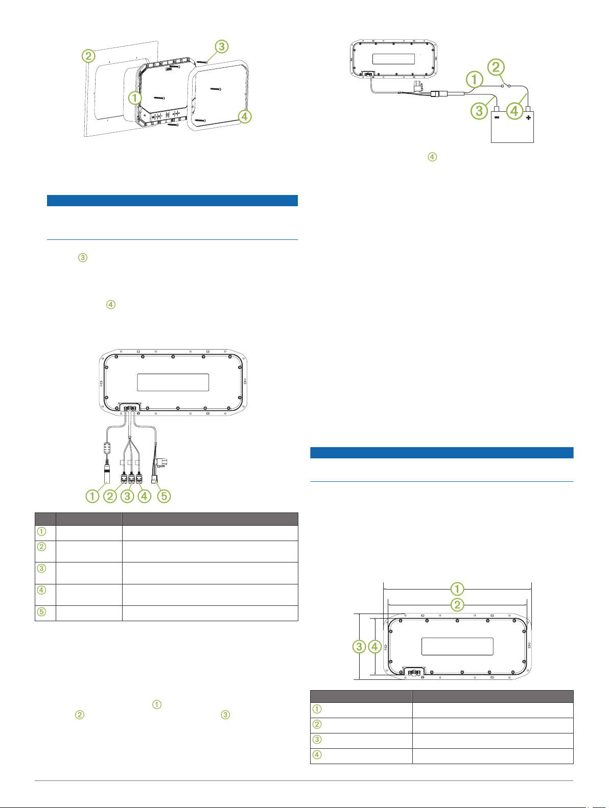
Connector Identification
If necessary, route a wire between the switch and the
2
battery .
Route the wiring-harness plug to the stereo.
3
Do not connect the wiring harness to the stereo until after all
of the bare wire connections have been made.
Connect the black wire to the negative (-) battery terminal.
4
Connect the red power wire to the ignition or another manual
5
switch, and connect the switch to the positive (+) battery
terminal if necessary.
Connect the wiring harness plug to the stereo.
6
Stereo Information
Registering Your FUSION Panel-Stereo
Help us better support you by completing our online registration
today.
• Go to www.fusionentertainment.com.
• Keep the original sales receipt, or a photocopy, in a safe
place.
Cleaning the Stereo
NOTE: This stereo is rated IP65 for protection in harsh
environments. It is not designed to withstand high pressure
water spray, which may occur when you wash down your
vehicle or vessel. Failure to carefully spray-clean the vehicle or
vessel may damage the product and void the warranty.
NOTICE
Do not use harsh or solvent-based cleaners on the stereo. Using
such cleaners may damage the product and void the warranty.
Clean all salt water and salt residue from the stereo grille with
1
a damp cloth soaked in fresh water.
Use a mild detergent to remove a heavy buildup of salt or
Item Connector Connects to
External antenna External AM/FM antenna
AUX IN 1 Audio sources, such as a CD player, TV, or
another FUSION stereo
AUX IN 2 Audio sources, such as a CD player, TV, or
another FUSION stereo
Line out RCA line out, switchable between variable and
fixed output
Power 12 V +, -/ground, and external amplifier on
2
stains.
Dimension Drawings
Rear View
Dimensions are shown without the trim attached.
Connecting to Power
When connecting the stereo to power, you should connect it
through the ignition or another manual switch.
If it is necessary to extend the power and ground wires, use
14 AWG (2.08 mm2) wire. For extensions longer than 1 m (3 ft.),
use 12 AWG (3.31 mm2) wire.
Route the red power wire to the ignition or another manual
1
switch , and route the black ground wire to the battery.
2 Important Safety Information
Dimension Measurement
341 mm (13.43 in.)
320 mm (12.61 in.)
152 mm (6 in.)
132 mm (5.19 in.)