

Garmin FISHFINDER 340C owner’s manual
Fishfinder 340C
full-featured color sonar
owner’s manual

© 2006 Garmin Ltd. or its subsidiaries
Garmin International, Inc.
1200 East 151st Street,
Olathe, Kansas 66062, U.S.A.
Tel. 913/397.8200 or 800/800.1020
Fax 913/397.8282
All rights reserved. Except as expressly provided herein, no part of this manual may be reproduced, copied, transmitted, disseminated,
downloaded or stored in any storage medium, for any purpose without the express prior written consent of Garmin. Garmin hereby grants
permission to download a single copy of this manual onto a hard drive or other electronic storage medium to be viewed and to print one
copy of this manual or of any revision hereto, provided that such electronic or printed copy of this manual must contain the complete text
of this copyright notice and provided further that any unauthorized commercial distribution of this manual or any revision hereto is strictly
prohibited.
Information in this document is subject to change without notice. Garmin reserves the right to change or improve its products and to make changes in the content
without obligation to notify any person or organization of such changes or improvements. Visit the Garmin Web site (www.garmin.com) for current updates and
supplemental information concerning the use and operation of this and other Garmin products.
Garmin®, CANet™, DynaColor™, and Ultrascroll™ are trademarks or registered trademarks of Garmin Ltd. or its subsidiaries and may not be used without the
express permission of Garmin.
Garmin (Europe) Ltd.
Unit 5, The Quadrangle, Abbey Park Industrial Estate,
Romsey, SO51 9DL, U.K.
Tel. 44/0870.8501241
Fax 44/0870.8501251
Garmin Corporation
No. 68, Jangshu 2nd Road, Shijr, Taipei County,
Taiwan
Tel. 886/2.2642.9199
Fax 886/2.2642.9099
January 2006 Part Number 190-00658-00 Rev. A Printed in Taiwan

INTRODUCTION > ABOUT THIS MANUAL
INTRODUCTION
Thank you for choosing the Garmin
Fishfinder 340C is a full-featured, color sonar that offers a choice
of display styles, a dual beam or dual frequency option, and many
®
Fishfinder 340C. The
About This Manual
To get the most out of your Fishfinder 340C, read this manual and
learn the operating procedures. This manual includes the following:
• Introduction—contains the Table of Contents, product
more features, including the following:
• Ultrascroll™, which gives you a much faster update rate on
• Getting Started
your Sonar Pages.
• Auto Gain, which enables you to see more fish and
• Installing the Fishfinder 340C—covers the installation and
structures.
• CANet™ capability, which enables you to connect your unit
• Using the Fishfinder 340C
to CANet-capable Garmin chartplotters, so you can read the
Sonar Pages on chartplotters located elsewhere in the boat.
• Appendix—contains information, such as specifications,
• Round flasher, which gives you an option for how to view
the sonar.
• Whiteline, which helps you to interpret bottom hardness.
• 2x and 4x automatic and manual zoom.
• Adjustable keel offset.
• Index—helps you quickly find information in this manual.
This manual uses the term Warning to indicate a potentially
hazardous situation, which, if not avoided, could result in death or
serious injury.
• Alarms for fish size, shallow water, deep water, and low
battery.
• NMEA sonar data output and navigation data input.
This manual uses the term Caution to indicate a potentially
hazardous situation, which, if not avoided, may result in minor
injury or property damage. It may also be used without the symbol
to alert you to avoid unsafe practices.
registration, contact, and cleaning information.
—provides general information that can
help you before you install and use your Fishfinder 340C.
testing for the Fishfinder 340C.
—provides details about the
features and operations of the Fishfinder 340C.
optional accessories, and messages that might appear. You
can also find warranty information in the Appendix.
Fishfinder 340C Owner’s Manual i

INTRODUCTION > PRODUCT REGISTRATION, CONTACT GARMIN, AND CARING FOR THE FISHFINDER
Product Registration
Help us better support you by completing our online registration
today! Have the serial number of your Fishfinder handy, and
connect to our Web site (http://www.garmin.com). Look for the
Product Registration link on our Home page.
Use this area to record the serial number (8-digit number located
on the back of the box). Be sure to keep your original sales receipt
in a safe place, or attach a photocopy inside the manual.
Serial Number: ___ ___ ___ ___ ___ ___ ___ ___
Contact Garmin
If you encounter any difficulty while using your Fishfinder, or if
you have any questions, in the U.S.A. contact Garmin Product
Support by phone: 913/397.8200 or 800/800.1020, Monday–
Friday, 8 AM–5 PM Central Time; or go to
www.garmin.com/support/ and click on Product Support. In
Europe, contact Garmin (Europe) Ltd. at 44/0870.8501241.
Caring for the Fishfinder
The Fishfinder case is constructed of high-quality materials and
does not require user maintenance except cleaning.
ii Fishfinder 340C Owner’s Manual
Cleaning the Case
Clean the Fishfinder’s outer casing (except for the screen) using
a cloth dampened with a mild detergent solution. Wipe it dry.
Avoid chemical cleaners and solvents that can damage plastic
components.
Cleaning the Screen
Apply eyeglass lens cleaner to a clean, lint-free cloth, and then
gently wipe the screen with the moistened cloth.
WARNING: The Fishfinder 340C lens is coated with a special
anti-reflective coating which is very sensitive to skin oils,
waxes, and abrasive cleaners. CLEANERS CONTAINING
AMMONIA WILL HARM THE ANTI-REFLECTIVE
COATING.
Storage
Do not store the Fishfinder where prolonged exposure to
temperature extremes might occur (such as in the trunk of a car),
because permanent damage can result.
Water Immersion
The Fishfinder is waterproof to IEC Standard 60529 IPX7. It can
withstand immersion in 1 meter of water for 30 minutes. Prolonged
submersion can cause damage to the Fishfinder. After submersion,
wipe and air dry the Fishfinder before reusing.

INTRODUCTION > TABLE OF CONTENTS
TABLE OF CONTENTS
Introduction ...........................................................................i
About This Manual ................................................................... i
Product Registration ............................................................... ii
Contact Garmin ....................................................................... ii
Caring for the Fishfinder ........................................................ ii
Warning ................................................................................... iv
Getting Started .....................................................................1
Packing List ............................................................................. 1
Optional Accessories .............................................................. 1
Understanding the Fishfinder and Sonar .............................. 2
Installing the Fishfinder 340C ............................................5
Selecting a Location for the Fishfinder ................................. 5
Mounting the Fishfinder ......................................................... 6
Mounting the Transducer ....................................................... 9
Installing the Wiring Harness ............................................... 15
Testing the Installation ......................................................... 19
Using the Fishfinder 340C ................................................21
Learning the Basic Functions .............................................. 21
Using Simulator Mode .......................................................... 22
Using the Fishfinder 340C Keypad ...................................... 23
Understanding the Main Pages ............................................ 24
Using the Main Menu ............................................................ 27
Using the Adjustment Menu ................................................. 36
Configuring Advanced Data Fields ...................................... 39
Pausing a Sonar or Flasher Page ........................................ 41
Marking a Waypoint ............................................................... 41
Appendix ............................................................................44
Specifications ........................................................................ 44
Optional Accessories ............................................................ 44
Messages and Alarms ........................................................... 45
Limited Warranty ................................................................... 46
Software License Agreement ............................................... 47
Index ...................................................................................48
Fishfinder 340C Owner’s Manual iii

INTRODUCTION > WARNING
Warning
WARNING: This product, its packaging, and its components contain chemicals known to the State of California to cause cancer, birth defects, or reproductive
harm. This Notice is being provided in accordance with California’s Proposition 65. If you have any questions or would like additional information, please refer
to our Web site at
http://www.garmin.com/prop65.
iv Fishfinder 340C Owner’s Manual

GETTING STARTED > PACKING LIST AND OPTIONAL ACCESSORIES
GETTING STARTED
Before installing and using your Fishfinder 340C, check to see that
your package includes the following items. The package number
is on the outside of the box. If any parts are missing, contact your
Garmin dealer immediately.
Optional Package (010-00505-02)
• Standard package
• Dual frequency (200/50kHz) plastic transom mount
transducer with depth and temperature and an attached
30-foot cable
Optional Package (010-00505-03 with Worldwide
Packing List
Standard Package (010-00505-00)
• Fishfinder 340C unit
• Tilt/swivel mount
• 6-foot data/power cable
• Owner’s manual
• Quick reference guide
• Flush mount template
• Protective cover
• Flush mount hardware kit
Optional Package (010-00505-01)
• Standard package
• Dual beam (14°/45°) plastic trolling motor/transom mount
transducer with depth and temperature and an attached
30-foot cable
Fishfinder 340C Owner’s Manual 1
Language Support)
• Standard package
• Dual frequency (200/50kHz) plastic transom mount
transducer with depth and temperature and an attached
30-foot cable
Optional Accessories
The following optional accessories are available at
www.garmin.com:
• Speed sensors
• Quick-release flush mount kit
• CANet
• Optional transducers and transducer accessories
™ connection kit

GETTING STARTED > UNDERSTANDING THE FISHFINDER AND SONAR
Understanding the Fishfinder and Sonar
The Fishfinder 340C is a fully automatic, color sonar unit that
allows you to go out on the water and find fish without having to
configure a lot of settings; or, if from experience you know exactly
how you want your Fishfinder screen to look and function, you can
customize each setting to your specific needs and wants.
If you have used a Fishfinder before, you might already know how
to interpret the sonar information on the screen, so you can skip
this section. If you have not used a Fishfinder before, you might
want to learn a bit about sonar: what it is, how it works, and what
you might see on the Fishfinder 340C screen. This manual does not
go into technical detail about sonar, but it can give you a general
understanding of those things that you need to know about sonar
that can help you interpret the screen and find the fish.
Understanding Sonar
During installation, you connect your Fishfinder 340C to a
transducer. The transducer uses sound to determine information
about what is in the water beneath your boat. Then the transducer
sends the information to your Fishfinder to be displayed on the
screen for you to view and interpret. How does the transducer do
this?
The transducer sends sound waves down into the water in a cone
shape, similar to a flashlight beam (covering a smaller circular area
at the top and angling out to a larger circular area at the bottom).
These sound waves reflect off of any object that they hit, and then
the waves travel back up to the transducer. These objects could be
fish, branches, the bottom, or any other object that has density that
is different from the water. The transducer receives the sound wave
information, and then sends the information to the Fishfinder. The
Fishfinder displays the information on the screen for you to see
and interpret. The type of transducer and settings that you choose
determine how the information is displayed on the screen.
Using Dual Frequency
Dual frequency works best for deep water (for example, off-shore)
applications. The 200 kHz frequency allows you access to great
detail about what is underneath your boat. The 50 kHz frequency
provides less detailed information, but penetrates to greater depths
with the same power. You can choose either or both frequencies to
get the information that you want. If you choose dual frequency,
the transducer alternates between the 50 kHz and 200 kHz signals.
This capability allows you to see the best picture available at any
depth.
2 Fishfinder 340C Owner’s Manual

GETTING STARTED > UNDERSTANDING THE FISHFINDER AND SONAR
Using Dual Beam
Dual beam works best for shallow water (for example, inland)
applications. A dual beam transducer can transmit a narrow or a
wide beam. The water area covered by the transmitted sound waves
The wide beam is more helpful in shallow water, because it gives
you a much wider view of objects in the water, including areas
beyond the sides of your boat. At a 30-foot depth, the wide beam
covers the area of approximately a 20-foot circle.
is determined by the beam width of the transducer and the water
depth. The narrow beam provides crisp detail of what is under your
boat, and is very helpful if you are fishing in deeper water where
the beam covers more area (for example, at a 30-foot depth, the
narrow beam covers the area of about a 7-foot circle).
Understanding the Fishfinder Screen
Experimentation and experience are the keys to successfully
interpreting your Fishfinder screen. We recommend that you take
your Fishfinder out on familiar water, and spend time learning to
interpret what you see on the Fishfinder 340C screen.
Think of the Fishfinder screen as if you took a picture from the
side of an aquarium in your home. You can see how deep a fish is
in the water (how close it is to the top or bottom), but you cannot
tell where the fish is located horizontally in the water (whether it is
near the front or the back of the aquarium). Remember this when
you are trying to locate exactly where something is in the water.
Narrow
Beam
Wide
Beam
Fishfinder 340C Owner’s Manual 3
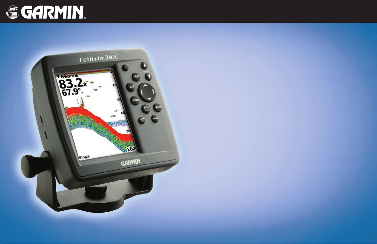
GETTING STARTED > UNDERSTANDING THE FISHFINDER AND SONAR
Water
depth
Bottom
Surface
Clutter
Depth
scale
Fish
Along the top of the screen, you might see a grouping of intense
colors. This area is
or any other sonar interference at the surface of the water. Too
much surface clutter can obscure your view of fish. You can turn
down the Gain setting to reduce this surface clutter.
The strongest sonar returns appear on your screen as the most
intense solid color (depending on your selected color scheme; red
is the default). The weakest returns appear as the less intense, less
solid colors (blue is the default).
Between the bottom and the surface clutter, you see fish in the
previous illustration. Here, the fish appear as arches. Actual fish
returns might not always appear as perfect arches, due to the speed,
fish orientation, or other conditions. You can turn on the Fish
Symbols setting if you want to see on-screen fish in a fish shape.
The bottom of the water is always going to be the strongest
signal, and therefore the most intense color. The bottom is the
continuous, intensely-colored line running across the bottom of
the screen. The Fishfinder 340C includes the latest technology in
The strength of the sonar return can also help you interpret the
hardness of the bottom of the water. The thicker the bottom line,
the harder the bottom.
interpreting bottom signals; it can see through fish, structures, and
thermoclines (shown in the weakest colors). Large schools of fish
or dense structures close to the bottom can affect water depth return
readings.
NOTE: If the Fishfinder is unable to track the bottom for any
reason, the digits in the depth window flashes on and off to
alert you that the Fishfinder is not tracking the bottom.
surface clutter, which can be caused by waves
Hard Structure Soft Structure
4 Fishfinder 340C Owner’s Manual

INSTALLING THE FISHFINDER 340C > SELECTING A LOCATION FOR THE FISHFINDER
INSTALLING THE FISHFINDER 340C
DO NOT mount the unit in an area that is exposed to extreme
temperature conditions.
To ensure the successful operation of your Fishfinder 340C, you
must properly install the Fishfinder and all of its related parts.
To install and use your Fishfinder, you must do the
following:
1. Select a proper location for the Fishfinder.
2. Mount the Fishfinder.
3. Install your transducer.
4. Connect to your power source.
5. Test the installation.
Each of these steps is described in detail in the following sections.
Selecting a Location for the Fishfinder
To get the best possible performance from your Fishfinder 340C:
• Read the instructions first, and then follow the instructions to
• Gather the appropriate fasteners and tools.
• Verify that all cables can reach the unit mounting location
Consider the following when you select an installation location:
• Wear safety goggles and a dust mask when drilling, cutting,
• Provides optimal viewing as you operate your vessel.
• Allows easy access to the unit’s keypad.
• Is strong enough to support the weight of the Fishfinder and
If you experience difficulty installing the unit, contact Garmin
Product Support or contact a professional installer.
protect it from excessive vibration or shock.
• Allows room for the routing and connection of the
power/
data and transducer cables. There should be at least a 3-inch
(8 cm) clearance behind the case.
NOTE: The temperature range for the Fishfinder 340C is 5°F
to 131°F (-15°C to 55°C). Extended exposure to temperatures
exceeding this range (in storage or operating conditions) may
cause failure of the LCD screen. This type of failure and related
consequences are NOT covered by the manufacturer’s limited
warranty.
install the unit.
and the transducer.
or sanding.
Fishfinder 340C Owner’s Manual 5
INSTALLING THE FISHFINDER 340C > MOUNTING THE FISHFINDER
Mounting the Fishfinder
There are two possible installation methods for your Fishfinder:
• You can mount the Fishfinder onto a bracket that attaches to
the console or overhead.
• You can flush mount the Fishfinder into a flat panel.
Surface Mounting the Fishfinder
The Fishfinder 340C’s compact, waterproof case is suitable for
mounting in exposed locations or at the nav station. The Fishfinder
comes with a tilt/swivel mounting bracket that can be used for
console or overhead mounting.
Mounting the Bracket Assembly
Tools (not included)—drill, screwdriver (Phillips or standard), and
one of the following:
• Three #8 (4 mm) pan-head machine bolts with matching nuts
and washers and a 5/32" (5 mm) drill bit.
OR
• Three #8 pan-head self-tapping screws and a 1/16" drill bit
for drilling starter holes.
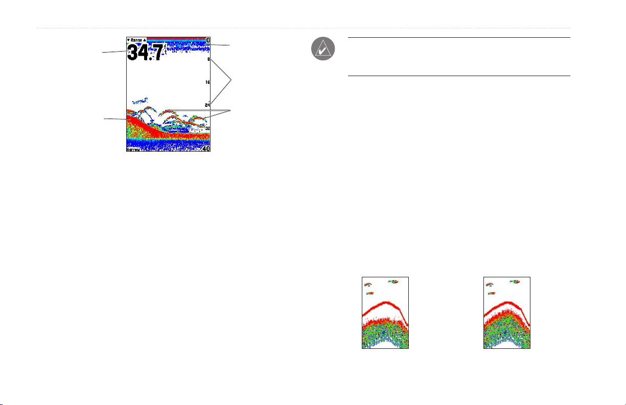
Use a pan-head machine bolt or self-tapping screw to secure the
swivel base. If you use a screw with a countersunk head, you risk
damaging the mounting bracket.
To mount the bracket assembly:
1. Using the swivel base as a template, mark the location of
2. Drill the mounting holes.
3. Secure the swivel base with three bolts or screws. DO NOT
OK
the three holes that secure the bracket to the mounting
surface.
• If you secure the base with machine bolts, drill three
5/32" (5 mm) holes at the locations you marked.
• If you secure the base with self-tapping screws, drill
starter holes at the locations you marked. Do not make
the starter holes deeper than half the screw length.
OVERTIGHTEN.
6 Fishfinder 340C Owner’s Manual
INSTALLING THE FISHFINDER 340C > MOUNTING THE FISHFINDER
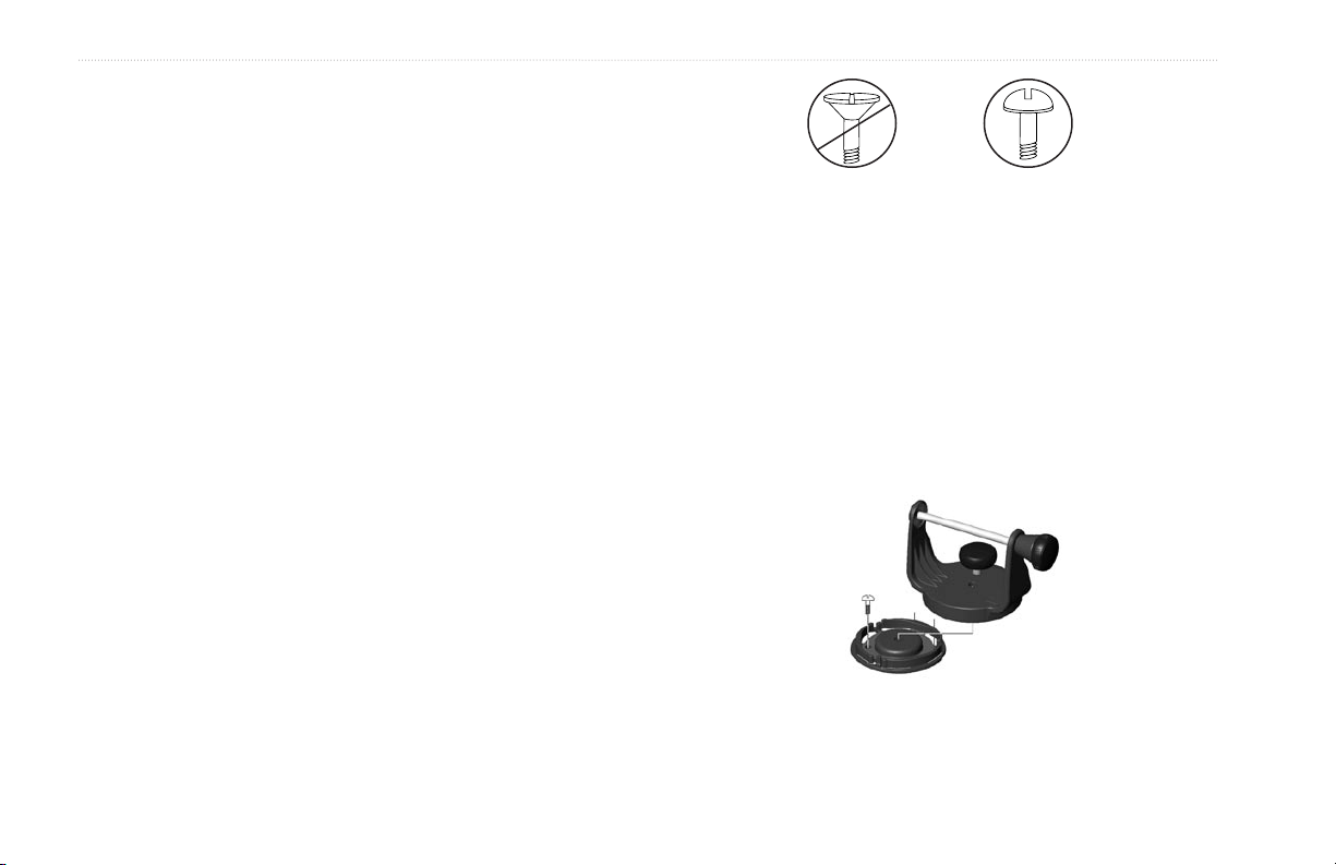
4. Place the swivel mount bracket over the swivel base and
secure it with the short knob.
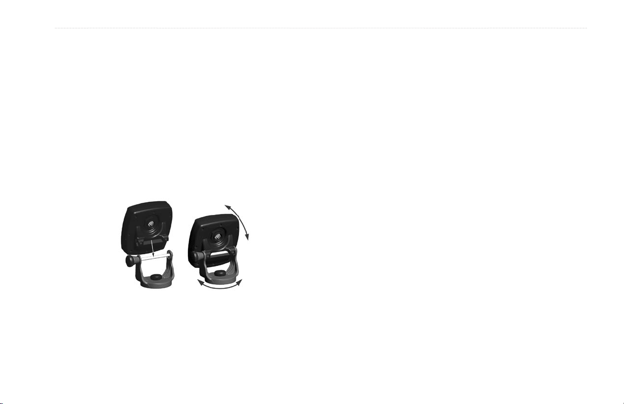
Installing the Unit on the Mounting Bracket
To install the Fishfinder on the mounting bracket:
1. Align the slot on the back of the Fishfinder with the long
mounting knob, and slide the Fishfinder into place. If
necessary, adjust the long knob to spread the bracket arms
apart. (Turn counter-clockwise to widen the bracket arms
and clockwise to tighten.)
2. Adjust the Fishfinder angle, and tighten the long mounting
knob until snug.
3. Rotate the swivel mount bracket by twisting it left or right.
The bracket clicks as you turn it. Select a good viewing
angle, and then tighten all knobs.
4. Connect the power/data and transducer cables to the back
of the Fishfinder, making sure the locking rings are fully
tightened on both connectors.
Flush Mounting the Fishfinder
You can flush mount the Fishfinder 340C into a flat panel.
• Select an appropriately sized location for the unit.
• Use the Flush Mount Template provided in the box to
determine a location.
• Check that all cables reach the unit mounting location.
• Always wear safety goggles and a dust mask when drilling,
cutting, or sanding.
Fishfinder 340C Owner’s Manual 7

INSTALLING THE FISHFINDER 340C > MOUNTING THE FISHFINDER
Included mounting hardware—(4) 3 mm studs, (4) flat washers,
and (8) 3 mm hex nuts.
Tools (not included)
—center punch, drill, 1/8" (3 mm) drill bit,
3/8" (6 mm) drill bit, jig saw, 1/16" (2 mm) Allen wrench, and 9/32"
(7 mm) wrench.
To flush mount the Fishfinder 340C:
1. Trim the Flush Mount Template, and tape it to the chosen
location.
2. Using a center punch, indent the center of each mounting
hole location.
3. Using an 1/8" (3 mm) drill bit, drill the four mounting holes.
4. Using a 3/8" (6 mm) drill bit, drill a hole for a location to
begin cutting the mounting surface.
5. Using the jig saw, cut the mounting surface along the inside
of the dashed line indicated on the template. Be very careful
when cutting this hole, there is only a small amount of
clearance between the Fishfinder and the mounting holes.
You can cut slightly inside the indicated line and then sand
or file the panel, as needed, to obtain the best fit.
6. Install the four mounting studs into the Fishfinder by
screwing the shorter section into the back of the Fishfinder.
Use a 1/16" (2 mm) Allen wrench to tighten the mounting
studs until the stop contacts the case. Be careful not to
overtighten, because this can damage the mounting stud!
The studs have a reusable thread-locking patch pre-applied
from the factory.
7. Place the Fishfinder into the cut out in the mounting surface.
8. Place washers over the mounting studs, and then thread
on one hex nut per mounting stud. Tighten all four until the
Fishfinder is snug against the mounting surface. Install and
tighten the second hex nut on all four mounting studs to lock
the first one into place.
Washer
Hex nut
Mounting Surface (Back View)
Studs
8 Fishfinder 340C Owner’s Manual
INSTALLING THE FISHFINDER 340C > MOUNTING THE TRANSDUCER
Mounting the Transducer
Proper transducer installation is key to getting the best performance
from your new Fishfinder. If the transducer lead is too short,
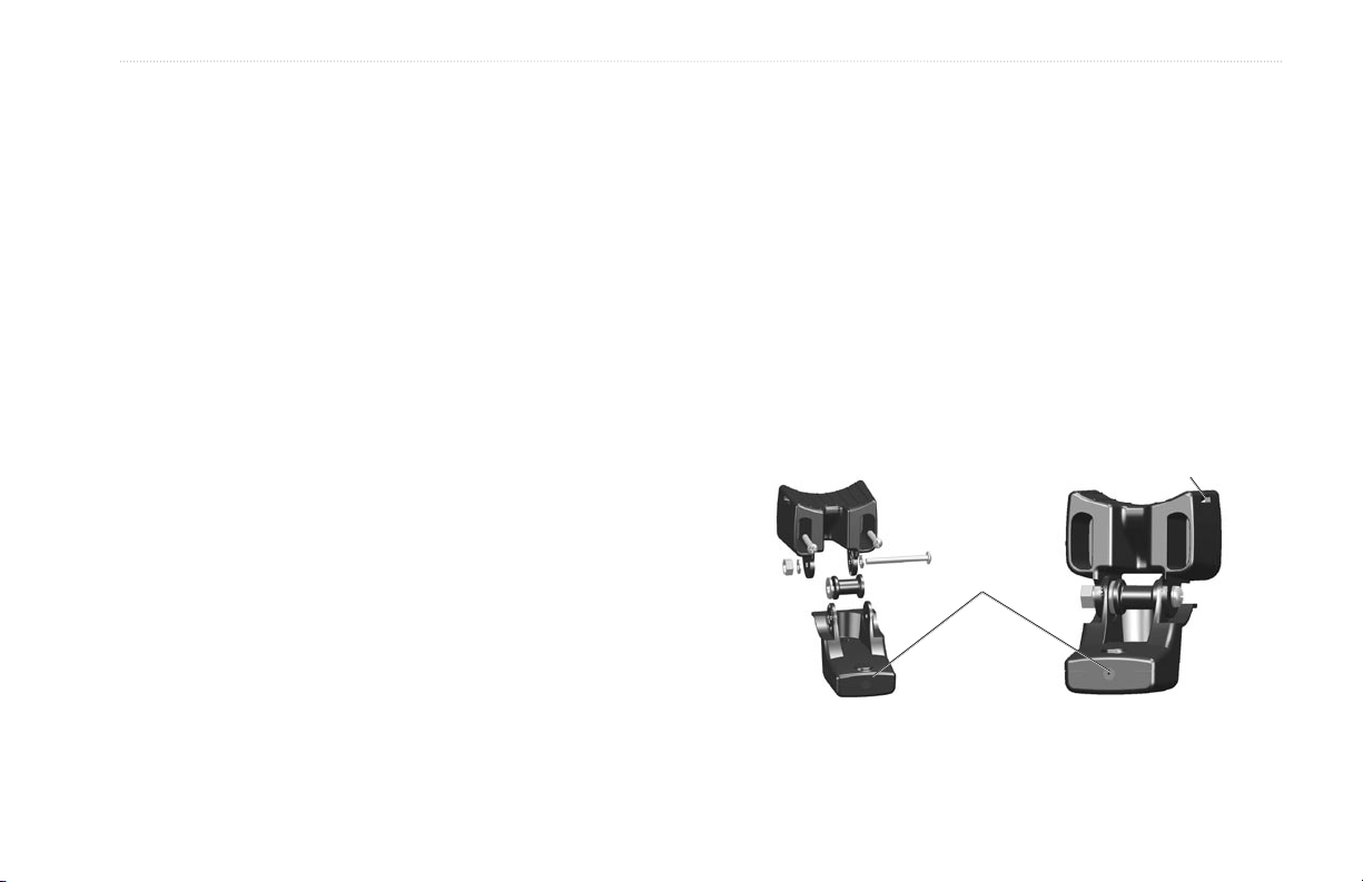
Assembling the Transducer
To assemble the transducer:
1. Insert the rubber washer and plastic spacer into the
extension cables are available from your Garmin dealer. Coil and
secure any excess cable. DO NOT cut the transducer lead or any
part of the transducer cable, because this voids your warranty. The
2. Route the cable toward the back of the transducer. Slide the
cable cannot be spliced and connected to any existing (Garmin or
non-Garmin) transducer cables.
3. Place a 5 mm flat washer on the 10-32 x 1.75" screw, and
Following are some tips and basic installation instructions for some
popular transducers. Detailed installation instructions are provided
in the transducer kits. Some transducers might have to be installed
4. Place the remaining 5 mm flat washer on the exposed
by a professional marine installer.
transducer at the same time. DO NOT lubricate the rubber
washer.
transducer into the transducer mount.
insert the screw through the transducer mount, spacer, and
rubber washer.
end. Install the 10-32 lock nut tight. You can tighten the
transducer further after installation on the boat.
Cable tie slot
Back of the transducer
Fishfinder 340C Owner’s Manual 9
INSTALLING THE FISHFINDER 340C > MOUNTING THE TRANSDUCER
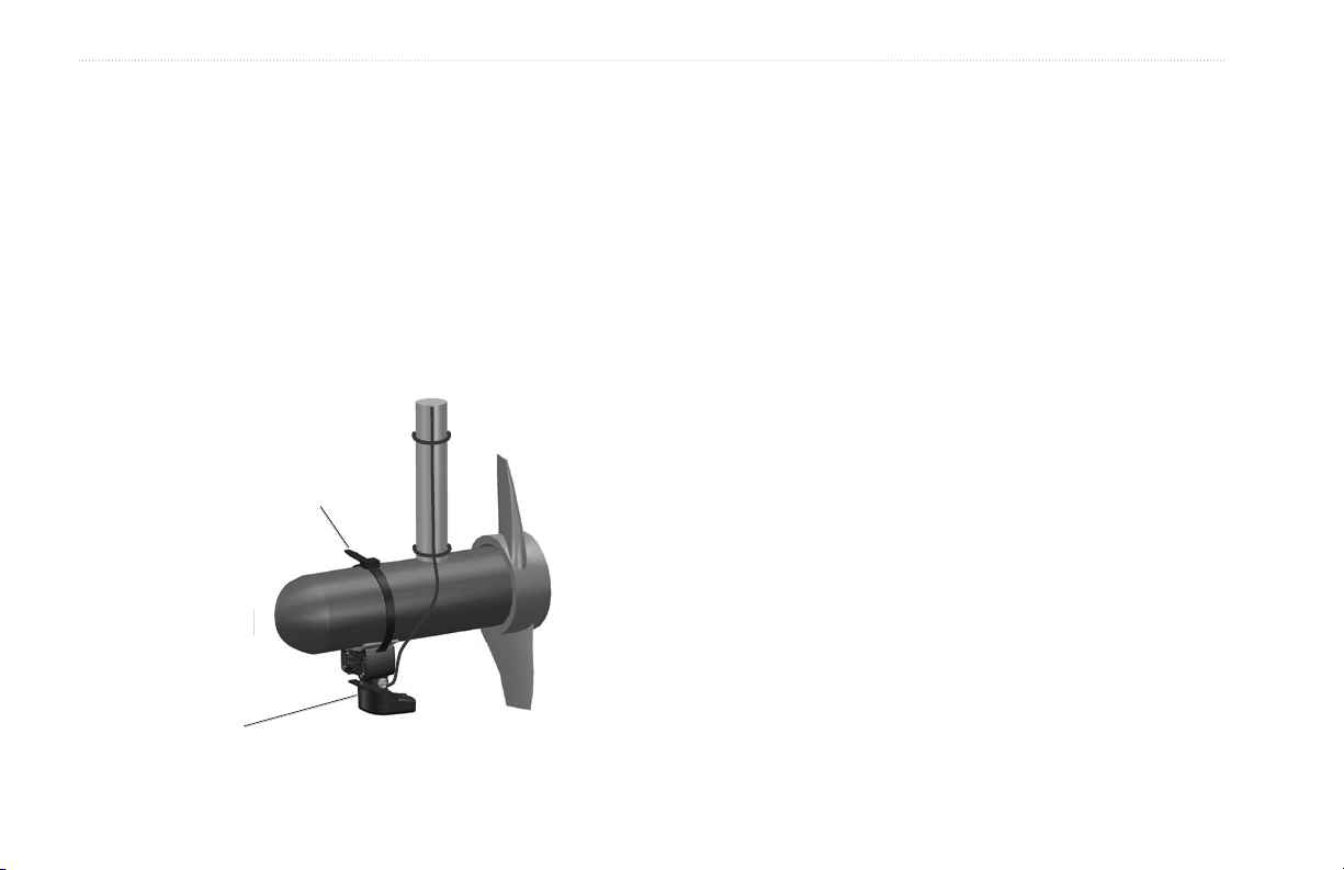
Mounting the Transducer on a Trolling Motor
(Dual Beam Only)
To mount the transducer on a trolling motor:
1. Slide the large cable tie through the slot on the transducer
mount (see the illustration on page 9) with the ridges of the
band facing up until equal lengths extend on both sides of
the mount. (NOTE: For cold water, or heavy timber or debris
areas, a metal 4-5" worm gear clamp is recommended.)
2. Position the mount gasket on the curved top of the
transducer mount.
Cable tie
3. Place the transducer assembly against the motor body of
the trolling motor, with the front of the transducer pointed
away from the trolling motor propeller.
4. Wrap the two ends of the cable tie around the motor body.
Place the pointed end of the cable tie through the fastener
hole on the opposite end and pull it through until it is snug
but not tight. (The cable tie clicks when you pull it.)
5. Position the transducer so that it is parallel with the bottom
when in use, and make sure the gasket is aligned properly.
Pull the cable tie end until tight. Trim off the excess, if
necessary. Tighten the 10-32 locking nut until it touches the
mounting bracket, and then tighten 1/4 turn more. (Do not
overtighten.)
6. Route the 30-foot (9 m) transducer cable using the supplied
cable ties to secure the cable to the motor shaft. You can
fill the forward-facing portion (except the cable tie pocket)
of the transducer mount with sealant to avoid accumulating
debris.
Front of the transducer
10 Fishfinder 340C Owner’s Manual
Mounting the Transducer on a Transom
When selecting a transom mount location, consider the following
for optimal performance:
• For your sonar to operate properly, the transducer must be
located in calm water. DO NOT mount the transducer behind
strakes, rivet lines, struts, fittings, water intake, discharge
ports, eroding paint, or anything that creates turbulence.
• Mount the transducer as close to the center of the boat as
possible.
• DO NOT cut the transducer lead. (This voids your warranty.)
• DO NOT mount the transducer in locations where it might
be jarred when launching, hauling, trailering, or storing.
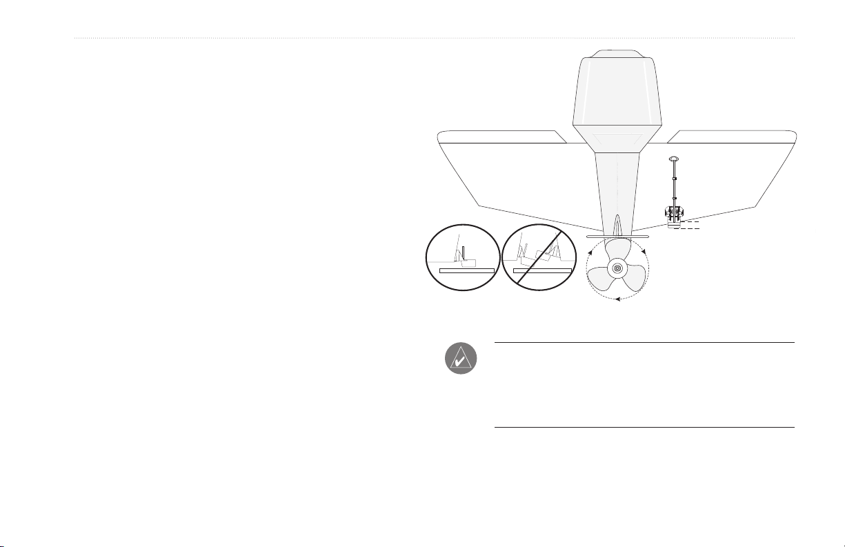
• DO NOT mount the transducer in the path of the prop on
single-drive boats. The transducer can cause cavitation that
can degrade the boat’s performance and damage the prop. On
twin-drive boats, mount the transducer between the drives, if
possible.
INSTALLING THE FISHFINDER 340C > MOUNTING THE TRANSDUCER
NOTE: DO NOT mount the transducer behind strakes, struts,
fittings, water intake or discharge ports, or anything that creates
air bubbles or causes the water to become turbulent. The
transducer must be in clean (non-turbulent) water for optimal
performance.
Fishfinder 340C Owner’s Manual 11

INSTALLING THE FISHFINDER 340C > MOUNTING THE TRANSDUCER
Tool List (not included)—drill, 3/8" wrench or socket, 5/32" and
1/8" drill bits, masking tape, #2 Phillips screwdriver, and marine
sealant.
To mount the transducer on a
1. Position the transducer mount at the selected transom
location. Make sure the transducer is parallel with the
water line. Mark the center locations of each hole on the
transducer mount. (See the figures on the next page.)
2. Using a 5/32" bit, drill the pilot holes approximately 1"
(25 mm) deep at the marked locations. To avoid drilling the
holes too deep, wrap a piece of tape around the bit at 1"
from the point of the bit.
3. Apply marine sealant to the 5 x 30 mm screws. Attach the
transducer assembly to the transom using the 5 x 30 mm
screws. Adjust the transducer assembly to extend beyond
the bottom of the transom approximately 1/8" (3 mm) on
fiberglass hulls or 3/8" (10 mm) on aluminum hulls. Adjust
the transducer assembly to be aligned parallel with the
water.
4. Tighten the 10-32 locking nut until it touches the
mounting bracket, and then tighten 1/4 turn more. (Do not
overtighten.)
transom:
5. Place the first cable clamp on the transducer cable
approximately one third of the distance between the
transducer and the top of the transom. Mark the location.
Using a 1/8" bit, drill a pilot hole approximately 3/8" (10 mm)
deep.
6. Attach the cable clamp using a 4 x 12 mm screw. Coat the
screw with marine sealant before installation. Repeat steps
5 and 6 using the other cable clamp.
7. Route the transducer cable, as needed, to the Fishfinder.
DO NOT CUT THE CABLE. Avoid routing the cable with
electrical wires or other sources of electrical interference.
(See the following illustration.)
12 Fishfinder 340C Owner’s Manual
 Loading...