

Garmin Fishfinder 250C, Fishfinder 250 User Manual
Fishfinder 250/250C
high-resolution sonar
owner’s manual
(Fishfinder 250C shown)

© Copyright 2005 Garmin Ltd. or its subsidiaries
Garmin International, Inc.
1200 East 151st Street
Olathe, Kansas 66062, U.S.A.
Tel. 913/397.8200 or 800/800.1020
Fax 913/397.8282
All rights reserved. Except as expressly provided herein, no part of this manual may be reproduced, copied, transmitted, disseminated, downloaded or stored in any
storage medium, for any purpose without the express prior written consent of Garmin. Garmin hereby grants permission to download a single copy of this manual
onto a hard drive or other electronic storage medium to be viewed and to print one copy of this manual or of any revision hereto, provided that such electronic
or printed copy of this manual must contain the complete text of this copyright notice and provided further that any unauthorized commercial distribution of this
manual or any revision hereto is strictly prohibited.
Information in this document is subject to change without notice. Garmin reserves the right to change or improve its products and to make changes in the content
without obligation to notify any person or organization of such changes or improvements. Visit the Garmin Web site (www.garmin.com) for current updates and
supplemental information concerning the use and operation of this and other Garmin products.
Garmin®, See-Thru®, and DCG (Depth Control Gain)® are registered trademarks of Garmin Ltd. or its subsidiaries and may not be used without the express
permission of Garmin.
Garmin (Europe) Ltd.
Unit 5, The Quadrangle
Abbey Park Industrial Estate
Romsey, SO51 9DL, U.K.
Tel. 44/0870.8501241
Fax 44/0870.8501251
Garmin Corporation
No. 68, Jangshu 2nd Road
Shijr, Taipei County, Taiwan
Tel. 886/2.2642.9199
Fax 886/2.2642.9099
May 2005 Part Number 190-00328-00 Rev. B Printed in Taiwan

INTRODUCTION
INTRODUCTION
Thank you for choosing the Garmin
product is designed for easy operation and to provide years of
reliable service.
Operations for the Fishfinder 250 and Fishfinder 250C are the
same unless othewise noted. To ensure that you get the most from
the Fishfinder 250/250C, take time to read this Owner’s Manual
and learn how to operate your new unit. This manual breaks down
into three main sections. Getting Started covers the installation
and testing for the Fishfinder 250/250C. Basic Operation provides
detailed references to the features and operations of the Fishfinder
250/250C and a basic overview of how sonar works and provides
information on interpreting sonar graphs. The Appendix contains
unit specifications and warranty information.
Product Support
If you encounter a problem or just have a question, our Product
Support Department can be reached Monday-Friday, 8 AM-5 PM
®
Fishfinder 250/250C. This
Enjoy your new Fishfinder 250/250C, and once again thank you for
choosing Garmin!
Product Registration
Help us to better support you by completing our online
registration today! Connect to our Web site (www.garmin.com) and
look for the Product Registration link on the Home page. Your unit’s
serial number is located on the back of the unit.
Use this area to record the serial number in case your Fishfinder
250/250C is lost, stolen, or in need of service. Be sure to keep your
original sales receipt in a safe place or attach a photocopy to these
instructions.
Serial Number: ___ ___ ___ ___ ___ ___ ___ ___
NOTE: If you have previously registered a Garmin product
purchase, we invite you to re-register using our online system.
Many services provided by our product registration system are
now automated and re-registering your purchase ensures you the
best possible support from Garmin.
Central Time.
Phone: 800/800.1020 or 913/397.8200
Online: http://www.garmin.com/contactUs/techSupport.jsp
Check the Garmin Web site (www.garmin.com) for links to Product
Support and Product FAQs.
Fishfinder 250/250C Owner’s Manual iii

TABLE OF CONTENTS
TABLE OF CONTENTS
Introduction .........................................................................iii
Product Support .............................................................................iii
Product Registration ......................................................................iii
Getting Started .....................................................................1
Packing List ............................................................................. 1
Transducers ............................................................................. 2
Optional Transducers ...................................................................... 2
Installation ............................................................................... 3
Selecting a Proper Location ............................................................ 3
Installing the Swivel Mount ........................................................... 3
Flush Mounting the Fishfinder 250/250C Unit ............................... 6
Connecting the Power/Data Cable .................................................. 7
Interfacing ....................................................................................... 8
Installing the Transducer .............................................................. 10
Transom Mount Installation .................................................... 10
Shoot-Thru-Hull Installation ................................................... 11
Testing the Installation .................................................................. 12
Basic Operation .................................................................13
Using the Keypad .................................................................. 13
Using the Sonar Page ........................................................... 14
Using the Adjustment Menu ................................................. 16
Adjustment Options ...................................................................... 17
Pausing the Sonar Page ................................................................. 20
Using the Main Menu ............................................................ 21
Graph Tab ..................................................................................... 21
Tools Tab ....................................................................................... 23
Configuring Advanced Data Fields ......................................... 23
Temp (Temperature) Tab .............................................................. 25
Alarms Tab .................................................................................... 25
System Tab ....................................................................................27
Units Tab ....................................................................................... 28
Sonar Tab ...................................................................................... 28
Time Tab ....................................................................................... 30
Understanding Sonar ............................................................ 31
Transducer Coverage .................................................................... 32
Understanding the Graph .............................................................. 33
Whiteline ...................................................................................... 34
Thermoclines ................................................................................ 35
Appendix ............................................................................36
Physical Specifications ........................................................ 36
Power ...................................................................................... 36
Sonar ...................................................................................... 36
Cleaning and Storage ........................................................... 36
Messages and Alarms ........................................................... 37
Software License Agreement ............................................... 38
Limited Warranty ................................................................... 38
Index ...................................................................................40
iv Fishfinder 250/250C Owner’s Manual

GETTING STARTED > PACKING LIST
GETTING STARTED
Packing List
Before installing and using your Fishfinder 250/250C, check to see
that your package includes the following items. The package part
number can be found on the outside of the box. If any parts are
missing, contact your Garmin dealer immediately.
Fishfinder 250 Standard Package (010-00343-00 w/o
transducer):
• Fishfinder 250 Unit
• Swivel-Mount Bracket and Knobs
• Power/Data Cable
• Owner’s Manual
• Self-Adhesive Quick Reference Guide
• Protective Cover
• Flush Mount Hardware Kit
Fishfinder 250 Optional Package (010-00343-01) includes
Standard Package, plus:
• Dual Frequency (200/50kHz, 10/40°) Plastic Transom Mount
Transducer with Depth and Temp
Fishfinder 250 Optional Package (010-00343-02) includes
Standard Package, plus:
• Single Frequency (200kHz, 14°) Plastic Transom Mount Transducer
with Depth and Temp
Fishfinder 250C Standard Package (010-00341-00 w/o
transducer):
• Fishfinder 250C Unit
• Swivel-Mount Bracket and Knobs
• Power/Data Cable
• Owner’s Manual
• Self-Adhesive Quick Reference Guide
• Protective Cover
• Flush Mount Hardware Kit
Fishfinder 250C Optional Package (010-00341-01) includes
Standard Package, plus:
• Dual Frequency (200/50kHz, 10/40°) Plastic Transom Mount
Transducer with Depth and Temp
• Separate Speed Sensor
Fishfinder 250C Optional Package (010-00341-02) includes
Standard Package, plus:
• Single Frequency (200kHz, 14°) Plastic Transom Mount Transducer
with Depth and Temp
• Separate Speed Sensor
NOTE: For the most recent list of available accessories for your
unit, current user manuals, and software updates, visit our Web
site at www.garmin.com.
Fishfinder 250/250C Owner’s Manual 1

GETTING STARTED > TRANSDUCERS
Transducers
The transducer acts as the eyes and ears of your sonar, transmitting
sound waves toward the bottom in a cone shape. Proper transducer
selection and installation are important to the operation of your unit.
Select a transducer that suits the depth of the water that you are on.
A wide cone angle transducer works best in shallower water,
providing a large coverage or viewing area, but at a decreased
bottom resolution. In deep water this can result in a large area
where fish cannot be seen. A narrow cone angle transducer is better
suited to deep water installations, providing a smaller coverage or
viewing area than a wide cone transducer, but with improved bottom
resolution and a smaller dead zone.
2 Fishfinder 250/250C Owner’s Manual
2 Fishfinder 250/250C Owner’s Manual
Optional Transducers
Included in the Optional Packages (page 1) are transom mount
transducers and separate speed sensors. These transducers provide
good all-around performance. In addition, a variety of optional
transducers are available from your local dealer or direct from
Garmin.
• 200/50kHz, 12/45°, plastic, transom mount, depth, temp
• 200/50kHz, 12/45°, plastic, transom mount, depth, temp, speed
• 200/50kHz, 12/45°, bronze, thru-hull mount, depth
• 200/50kHz, 12/45°, bronze, thru-hull mount, depth, temp, speed
• 200/50kHz, 12/45°, bronze, thru-hull mount/long stem, depth, temp,
speed
• 200/50kHz, 12/45°, plastic, thru-hull mount, depth
• 200/50kHz, 12/45°, plastic, adjustable. in-hull mount
• 200kHz, 14°, plastic, transom mount, depth
• 200kHz, 14°, plastic, transom mount, depth, temp
• 200kHz, 14°, plastic, transom mount, depth, temp, speed
• 200kHz, 8°, plastic, transom mount, depth, temp
• 200kHz, 8°, plastic, transom mount, depth, temp, speed
• 200kHz, 12°, bronze, thru-hull mount, depth
• 200kHz, 12°, bronze, thru-hull mount, depth, temp
• 200kHz, 9°, bronze, thru-hull mount, depth, temp, speed
• 200kHz, 12°, plastic, thru-hull mount, depth
• 200kHz, 12°, plastic, thru-hull mount, depth, temp
• 200kHz, 14°, plastic, in-hull mount, depth
• 200kHz, 14°, plastic, trolling motor mount, depth, temp

GETTING STARTED > INSTALLATION
Installation
The Fishfinder 250/250C must be properly installed according to
the following instructions to get the best possible performance. To
complete the installation, you need the appropriate fasteners and
tools. Verify that all cables can reach the unit mounting location, and
take time to read through these instructions prior to installation. Be
sure to always wear safety goggles and a dust mask when drilling,
cutting, or sanding. If you experience difficulty installing the unit,
contact Garmin Product Support or seek the assistance of a
professional installer.
Selecting a Proper Location
Choose a location that provides optimal viewing as you operate
When choosing a location for the unit, consider the following
conditions:
• There should be at least a 3” (8 cm) clearance behind the case
to allow connection of the transducer and power/data cables.
• The mounting surface should be sturdy enough to support the
unit and protect it from excessive vibration and shock.
NOTE: The temperature range for the Fishfinder 250/250C
is 5°F to 130°F (-15°C to 55°C). Extended exposure to
temperatures outside this range (in storage or operating
conditions) may cause failure of the LCD screen. This type
of failure and related consequences are NOT covered by the
manufacturer’s limited warranty.
the vessel and allows easy access to the unit’s keypad. Select a
mounting surface capable of supporting the weight of the unit and
protecting it from excessive vibration and shock. DO NOT mount
the unit in an area exposed to extreme temperature conditions. When
installing the mounting bracket, allow room for the routing and
connection of the power and transducer cables.
Installing the Swivel Mount
The Fishfinder 250/250C’s compact, waterproof case is suitable
for mounting in exposed locations or at the nav station. The unit
comes with a swivel-mount bracket that can be used for console or
overhead mounting.
Fishfinder 250/250C Owner’s Manual 3
GETTING STARTED > INSTALLATION
To install the swivel-mount bracket:
Tools (not included)—Drill, screwdriver (Phillips or
standard), and either of the following:
• Three #8 (4mm) pan head machine bolts with matching
nuts and washers and a 5/32” (5mm) drill bit.
• Three #8 pan head self-tapping screws and an
appropriately-sized drill bit for drilling starter holes.
1. Using the swivel base as a template, mark the location of
the three holes that are used to secure the bracket to the
mounting surface.
2. Drill the mounting holes.
• If securing the base with machine bolts, drill three 5/32”
(5mm) holes at the locations you marked.
• If securing the base with self-tapping screws, drill starter
holes at the locations you marked. Starter holes should
generally be no deeper than half the screw length.
3. Secure the swivel base with three bolts or screws. DO NOT
OVERTIGHTEN.
4. Place the rest of the mount over the swivel base and secure
with the short knob.
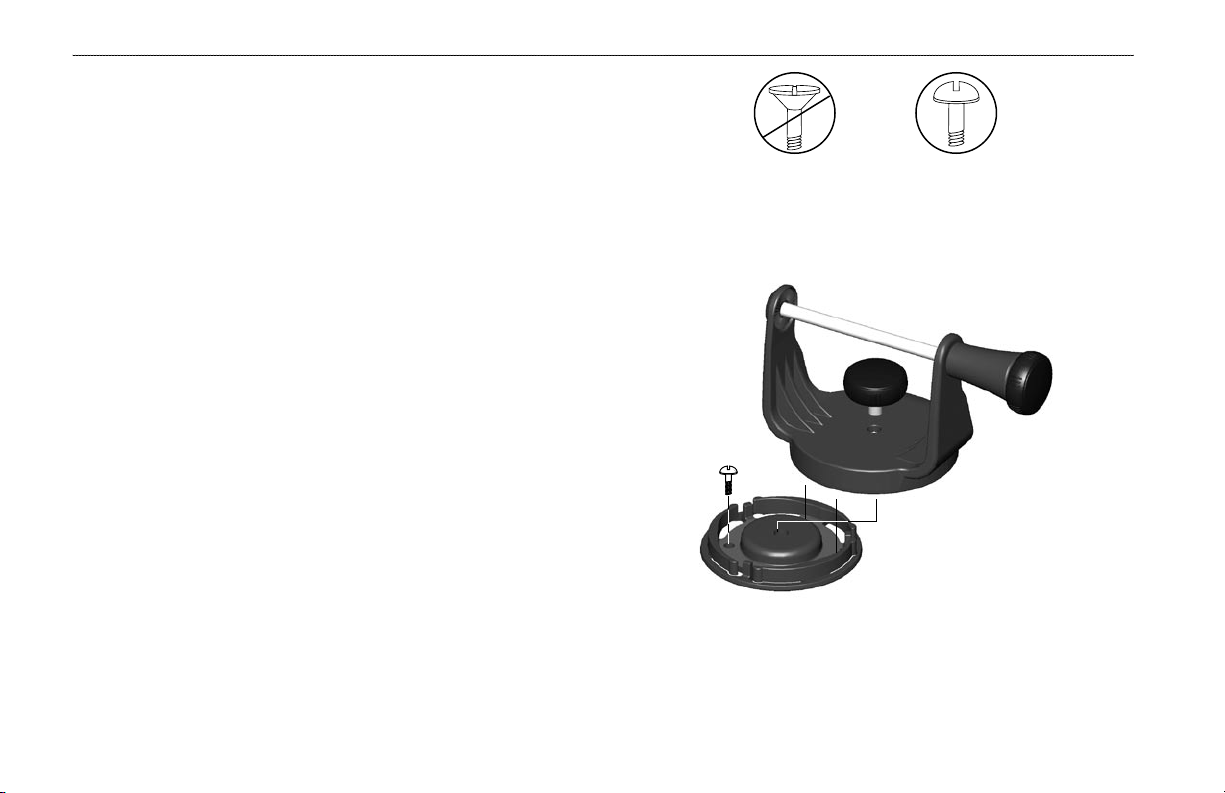
OK
The swivel base is designed to be secured using a pan head screw
or machine bolt. If you use a screw with a countersunk head, you risk
damaging the mounting bracket.
Secure the base and attach the mount.
4 Fishfinder 250/250C Owner’s Manual

To install the unit on the bracket
1. Align the slot on the back of the unit with the long mounting
knob, and slide the unit into place. You may need to adjust
the long mounting knob to spread the bracket arms apart.
(Turn counter-clockwise to widen the bracket arms, clockwise
to tighten.)
2. Adjust the unit angle and tighten the long mounting knob until
snug.
3. To tilt the unit, loosen the long mounting knob on the right
side of the bracket assembly.
4. To rotate the entire bracket, twist it left or right. The bracket
clicks as you turn it.
5. Tighten all knobs once the desired viewing angle is obtained.
GETTING STARTED > INSTALLATION
Slide the unit onto the bracket.
Adjust for optimal viewing.
Fishfinder 250/250C Owner’s Manual 5

GETTING STARTED > INSTALLATION
Flush Mounting the Fishfinder 250/250C Unit
NOTE: Be very careful when cutting this hole; there is only a
The Fishfinder 250/250C can be flush mounted on a flat panel. When
flush mounting the Fishfinder 250/250C, choose an appropriately
sized location for the unit. Use the Flush Mount Template provided
in the box to determine a location. Check that all cables reach the
unit mounting location before beginning installation. Always wear
safety goggles and a dust mask when drilling, cutting, or sanding.
To flush mount the Fishfinder 250/250C:
Included mounting hardware—Four 3mm studs, four flat
washers, and eight 3mm hex nuts.
Tools (not included)—Center punch, drill, 1/8” (3mm) drill bit,
3/8” (6mm) drill bit, jig saw, 1/16” (2mm) Allen wrench, and
9/32” (7mm) wrench.
1. Trim the Flush Mount Template and tape it in the appropriate
location.
2. Using a center punch, indent the center of each mounting
hole location.
3. Using a 1/8” (3mm) drill bit, drill the four mounting holes.
4. Using a 3/8” (6mm) drill bit, drill a hole for a location to begin
cutting the mounting surface.
5. Using the jig saw, cut the mounting surface along the inside
of the dashed line indicated on the template.
small amount of clearance between the unit and the mounting
holes. It may be prudent to cut slightly inside the indicated line
and then sand or file the panel as needed to obtain the best fit.
6. Install the four mounting studs into the unit by screwing the
shorter section into the back of the unit. Use a 1/16” (2mm)
Allen wrench to tighten the mounting studs until the stops
contact the case. Be careful not to overtighten, as this may
damage the mounting stud. The studs have a reusable
thread-locking patch preapplied from the factory.
Hex nuts
Washer
Studs
7. Place the unit in position
inside the cutout area of
the mounting surface.
8. Place washers over the
mounting studs, then
thread on one hex nut per
mounting stud. Tighten
all four hex nuts until the
unit is snug against the
Mounting surface (as seen from back)
mounting surface. Install
and tighten the second hex
nut on all four mounting
studs to lock the first hex nut in place.
6 Fishfinder 250/250C Owner’s Manual

GETTING STARTED > INSTALLATION
2A
-
+
Connecting the Power/Data Cable
The power/data cable connects the Fishfinder 250/250C to a 10-35
Volt DC system and provides interface capabilities for connecting
external devices. The color code in the diagram (page 9) indicates
the appropriate harness connections. If it is necessary to extend
the power/data wires, use a wire of comparable size and keep your
extension as short as possible.
The unit can be wired directly to your boat’s battery or to an unused
holder on your boat’s fuse block. When connecting the unit directly
to the battery, make sure the 2-Amp in-line fuse supplied with the
unit is installed. If needed, use a 2-Amp ACG/3AG replacement
fuse. If you decide to route power through the boat’s fuse block,
remove the in-line fuse holder on the unit’s power/data cable.
To connect the power/data cable to a voltage source:
1. Determine the polarity of the voltage source using a test light
or voltmeter.
2. Connect the Red (+ or positive) wire to the positive voltage
terminal. (If using the boat’s fuse block, route the positive
connection through the fuse, as shown on the diagram.)
3. Connect the Black (- or ground) wire to the negative voltage
terminal.
4. Install or check the 2-Amp fuse (either on the boat’s fuse
block or in the in-line holder).
To 10-35 Volt boat supply
2-Amp
fuse
Boat ground
Black wire
Red wire
To Fishfinder 250/250C
Fishfinder 250/250C Owner’s Manual 7

GETTING STARTED > INSTALLATION
The Fishfinder 250/250C can be connected to another piece of
NMEA compatible electronic equipment, such as a Garmin GPS
(Global Positioning System). If equipped with a capable transducer,
the Fishfinder 250/250C can send depth, temperature, and speed
information to the NMEA device. It can also mark a location (page
20) that could be displayed on another device and can accept
GPS navigational data (page 23), such as position, time, course,
distance, etc. Refer to the wiring diagram on the following page for
interfacing the Fishfinder 250/250C with other devices.
Interfacing
The Fishfinder 250/250C allows for NMEA 0183, Version 2.3
input/output with a compatible GPS or navigation device. NMEA
Input/Output must be set to On to send/receive data (page 27).
For additional information on using your Fishfinder 250/250C with
NMEA devices, see pages 20 and 27.
The following sentences are for NMEA 0183, Version 2.3:
Input—GPBOD, GPBWC (only used if RMB not present),
GPGGA, GPGLL (only used if GGA not present), GPRMB,
To connect the power/data cable to a GPS or other
GPRMC, GPXTE (only used if RMB not present)
NMEA device:
1. Follow steps 1-4 of the voltage source installation (page
7). For Garmin units, the ground (Black) wires serve as
data ground and must be attached together or on the same
terminal. Refer to the wiring diagram of your GPS unit for
wire identification.
2. Connect the Blue (Data OUT) wire from the Fishfinder to the
Data IN wire on the GPS/NMEA harness.
3. Connect the Brown (Data IN) wire from the Fishfinder to the
Data OUT wire on the GPS/NMEA harness.
4. Set the Fishfinder 250/250C NMEA Input/Output to On
(page 27). For Garmin GPS units, set the communications
interface to NMEA/NMEA, NMEA In/NMEA Out, or NMEA.
Output—SDDBT, SDDPT, SDMTW, SDVHW, SDWPL* (only if a
waypoint is “marked” in Pointer mode)
*Garmin GPS units will accept an SDWPL (WPL) NMEA sentence and create a
waypoint (saved location) at that position (page 20). For compatibility with other
brands of GPS or NMEA capable navigation devices, check with those manufacturers
to see if their units accept/store NMEA 0183 SDWPL sentences/waypoints. The
Fishfinder 250/250C does not store the actual waypoint. Only the receiving device, if
capable, will store the waypoint.
8 Fishfinder 250/250C Owner’s Manual
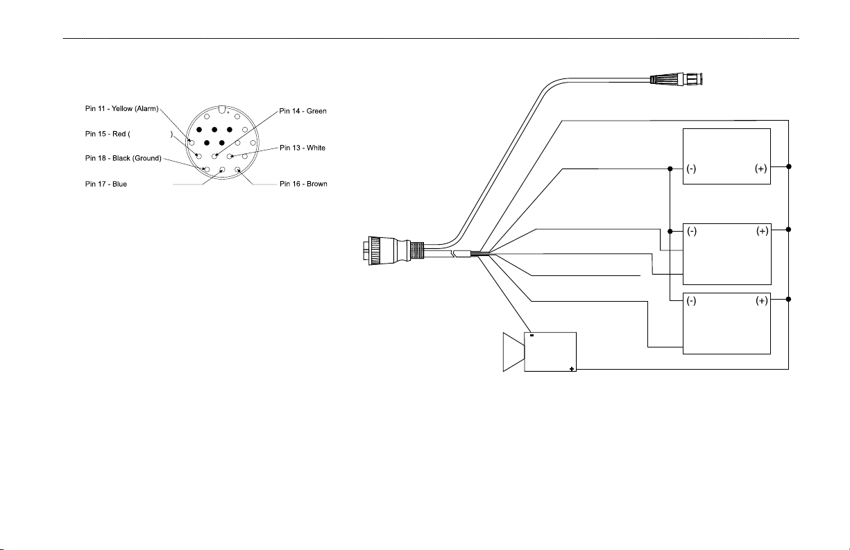
(Red) + 10-35 VDC
(Black) - Ground (Power/Data)
(Blue) Port 1 Data OUT
(Brown) Port 1 Data IN
(White) Port 2 Data IN (N/C)
(Green) Port 2 Data OUT
(Yellow) Alarm Low
GPS/NMEA
Device
RXD +
NMEA Device
10-35 Volts DC
Power
and RXD -
RXD +
TXD +
Alarm Relay
100ma max
coil current
To Transducer
To Unit
DC Positive
(RX COM 1)
(TX COM 1)
(RX COM 2)
(TX COM 2)
GETTING STARTED > INSTALLATION
During a typical installation, only the Red and Black
wires are used. The other wires do not have to be
connected for normal operation of the unit.
Complete information concerning National Marine
Electronics Association (NMEA) format and
sentences is available for purchase from NMEA at:
NMEA
Seven Riggs Avenue
Severna Park, MD 21146 U.S.A.
www.nmea.org
Fishfinder 250/250C Owner’s Manual 9
You can download a copy of Garmin's proprietary
communication protocol document from the Support
section of our Web site at www.garmin.com.
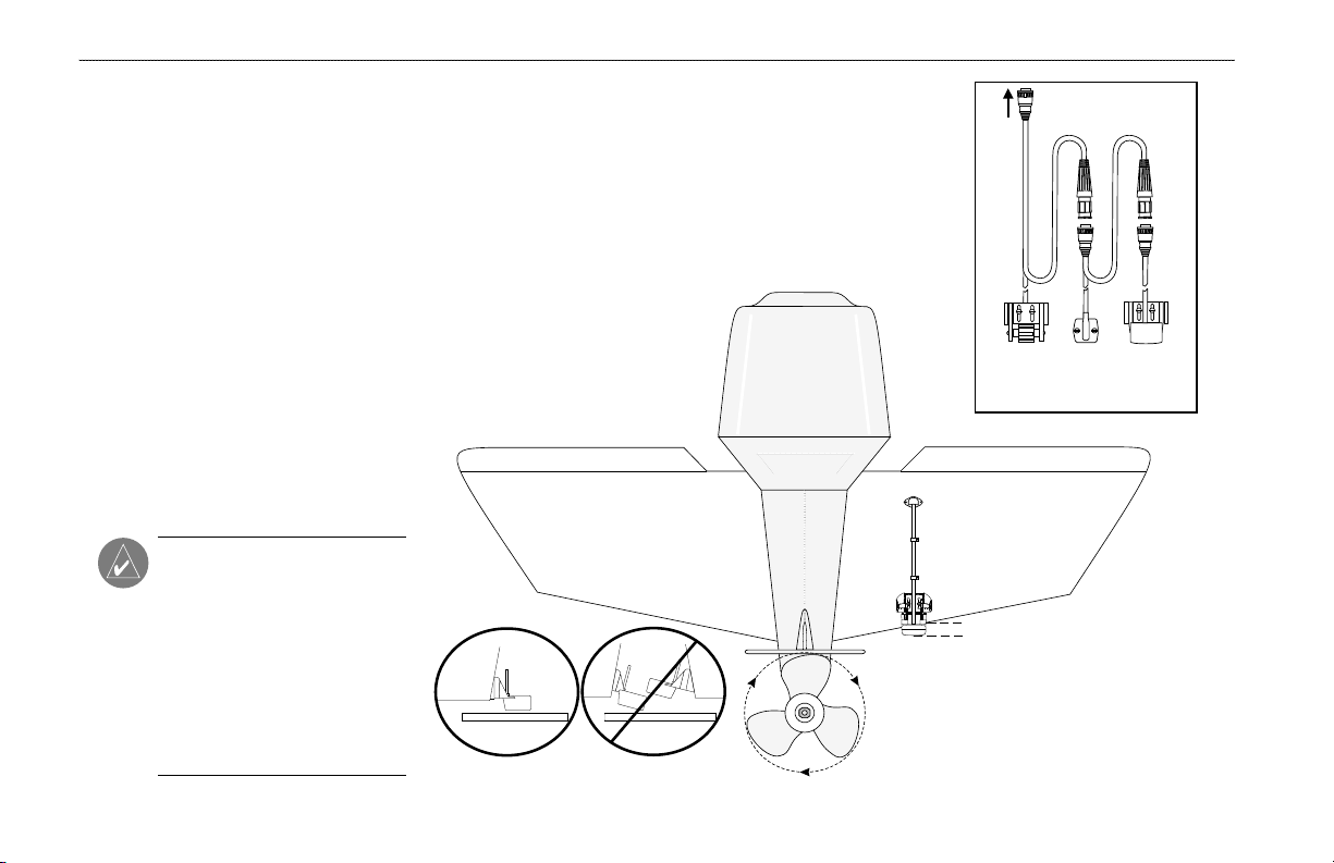
Speed Temp
Transducer
To Unit
GETTING STARTED > INSTALLATION
Installing the Transducer
Proper transducer installation is key to getting the best performance
from your new unit. If the transducer lead is too short, extension
cables are available from your Garmin dealer. Coil and secure any
excess cable. DO NOT cut the transducer lead or any part of the
transducer cable, as this will void your warranty. The cable cannot
be spliced and connected to any existing (Garmin or non-Garmin)
transducer cables.
Following are some tips and basic installation instructions for
some popular transducers. Detailed installation instructions are
provided in the transducer kits. Some transducers may need to be
installed by a professional marine installer.
Transom Mount Installation
Transom Mount Transducer (depth/temp)
Connecting a Transducer
to Multiple Sensors
NOTE: DO NOT mount the
transducer behind strakes,
struts, fittings, water intake or
discharge ports, or anything that
creates air bubbles or causes the
water to become turbulent. It is
important that the transducer be
in clean (non-turbulent) water
10 Fishfinder 250/250C Owner’s Manual
for optimal performance.
 Loading...