


 Loading...
Induction Designer Series
RTCSmp® Built-In Line Dual Cook-Top Models
Installation, Operation and Maintenance Manual
This manual is updated as new information and models are released. Visit our website for the latest manual.
Part Number 4532285 1/15

Safety Notices
Safety Notices
DEFINITIONS
 DANGER
Indicates a hazardous situation that, if not avoided, will result in death or serious injury. This applies to the most extreme situations.
nWarning
Indicates a hazardous situation that, if not avoided, could result in death or serious injury.
,Caution
Indicates a hazardous situation that, if not avoided, could result in minor or moderate injury.
Notic
Indicates information considered important, but not hazard-related (e.g. messages relating to property damage).
NOTE: Indicates useful, extra information about the procedure you are performing.
DESCRIPTIONS OF SAFETY SYMBOLS AND WARNINGS ON UNIT
This symbol alerts you to a hazardous situation that WILL or COULD cause serious bodily harm or death. Be alert and implement relevant safety precautions.
DANGER - HIGH VOLTAGE
This dangerous voltage warning symbol indicates a risk of electric shock and hazards from dangerous voltage.
Electromagnetic Field
 Warning
RISK OF FIRE OR ELECTRIC SHOCK! DO NOT OPEN!
To reduce the risk of fire or electric shock, do not remove or open cover. No user serviceable parts inside.
Refer servicing to qualified personnel.
CAUTION  ATTENTION
DISCONNECT FROM SUPPLY CIRCUIT BEFORE OPENING
DISCLAIMERS
 DANGER
Disregarding any safety instructions may cause harm to people, the surroundings, and the equipment. Garland is not responsible for any damages or personal injury caused by failure to observe any safety requirements. Risks involved when disregarding safety precautions include, but not limiting to:
•Death or injury caused by electric shock.
•Burn injury caused by contacting overheated cooking surface, cookware, or oil and grease.
•Damage to the equipment caused by using unsuitable cookware.
 DANGER
This product has been certified as commercial cooking equipment and must be installed by professional personnel as specified.
 DANGER
Do not install or operate equipment that has been misused, abused, neglected, damaged, or altered/ modified from that of original manufactured specifications.
 DANGER
Contact Manitowoc Foodservice if you intend to make any changes on the equipment. For safety reasons, always use genuine parts and accessories approved by Manitowoc. Refer to the warranty documents for your equipment.
 DANGER
Owners and operators are cautioned that maintenance and repairs must be performed by an authorized service agent using only genuine Garland replacement parts. Garland will have no obligation with respect to any product that has been improperly installed, adjusted, operated or not maintained in accordance with national and local codes and/or installation instructions provided with the product or any product that has its serial number defaced, obliterated or removed, and/or which has been modified or repaired using unauthorized parts or by unauthorized service agents.
3
Safety Notices
 DANGER
Improper installation, adjustment, alteration, service, or maintenance of this appliance or installation of a damaged appliance can result in DEATH, INJURY, EQUIPMENT DAMAGE, and void the warranty. NEVER install damaged appliances, equipment, or accessories.
ALWAYS have installation and service performed by trained and authorized personnel.
 DANGER
All utility connections and fixtures must be maintained in accordance with local and national codes.
nWarning
Do Not Store Or Use Gasoline Or Other Flammable Vapors Or Liquids In The Vicinity Of This Or Any Other Appliance. Never use flammable oil soaked cloths or combustible cleaning solutions, for cleaning.
nWarning
Warning labels mounted directly on the equipment must be observed at all times and kept in a fully legible condition.
nWarning
Read this manual thoroughly before operating, installing or performing maintenance on the equipment. Failure to follow instructions in this manual can cause property damage, injury or death.
This manual must always be available for reference at the place of operation.
nWarning
This product contains chemicals known to the State of California to cause cancer and/or birth defects or other reproductive harm. Operation, installation, and servicing of this product could expose you to airborne particles of glass-wool or ceramic fibers, crystalline silica, and/or carbon monoxide. Inhalation of airborne particles of glass-wool or ceramic fibers is known to the State of California to cause cancer. Inhalation of carbon monoxide is known to the State of California to cause birth defects or other reproductive harm.
Notic
Routine adjustments and maintenance procedures outlined in this manual are not covered by the warranty.
NOTE: Proper installation, care and maintenance are essential for maximum performance and trouble-free operation of your equipment. Visit our website www.mtwkitchencare.com for manual updates, translations, or contact information for service agents in your area.
NOTE: Throughout this manual, the induction unit type indicated on the front cover is referred to as “induction unit” or “unit” or "equipment".
nWarning
This appliance is not intended for use by persons (including children) with reduced physical, sensory or mental capabilities, or lack of experience and knowledge, unless they have been given supervision concerning use of the appliance by a person responsible for their safety. Do not allow children to play with this appliance.
4
Safety Notices
CODE
nWarning
Authorized Service Representatives are obligated to follow industry standard safety procedures, including, but not limited to, local/national regulations for disconnection / lock out / tag out procedures for all utilities including electric, gas, water and steam.
PERSONAL PROTECTION
 DANGER
All utilities (gas, electric, water and steam) must be OFF to all equipment and locked out of operation according to national/regional, as well as company approved practices during servicing. Always allow unit to cool.
 DANGER
Use appropriate safety equipment during installation and servicing.
 DANGER
Never stand on the unit! They are not designed to hold the weight of an adult, and may collapse or tip if misused in this manner.
 DANGER
Keep power cord AWAY from HEATED surfaces. DO NOT immerse power cord or plug in water. DO NOT let power cord hang over edge of table or counter.
 DANGER
To avoid cardiac pacemaker malfunction, consult physician or pacemaker manufacture about effects of electromagnetic field on pacemaker.
nWarning
Use caution when handling metal surface edges of all equipment.
nWarning
Risk of burns from high temperatures. You may get burnt if you touch any of the parts during cooking. Surfaces close to the cooking surface including side panels may get hot enough to burn skin. Use extreme caution to avoid coming in contact with hot surfaces or hot grease. Wear personal protective equipment.
CORRECT DISPOSAL OF THIS PRODUCT
This marking shown on the product indicates that the product should not be disposed as household waste or regular commercial waste. Instead it shall be handed over to the applicable collection
point for the recycling of electrical and electronic equipment. By ensuring this product is disposed correctly, you will help prevent potential harm to the environment or human health, which could otherwise be caused by inappropriate waste handling of this product.
For more detailed information regarding recycling of the product, please contact your local city office or your waste disposal service.
 DANGER
Induction units, sent for disposal, can be brought back into operation and their use must be avoided.
NOTE: The unit is built with common electrical, electromechanical, and electronic parts. No batteries are used.
NOTE: The owner and operator are responsible for the proper and safe disposal of the unit.
5
THIS PAGE INTENTIONALLY LEFT BLANK

Table of Contents
Safety Notices |
|
Definitions................................................................................................................................................. |
3 |
Descriptions of safety symbols and Warnings on Unit.............................................................. |
3 |
Disclaimers................................................................................................................................................ |
3 |
Code............................................................................................................................................................. |
5 |
Personal Protection................................................................................................................................ |
5 |
Correct Disposal of This Product....................................................................................................... |
5 |
Table of Contents |
|
Section 1 |
|
General Information |
|
Nomenclature and Model Numbers.................................................................................. |
9 |
Warranty Information......................................................................................................... |
9 |
Packing Slip......................................................................................................................... |
9 |
Serial Plate Location........................................................................................................... |
9 |
Compliances........................................................................................................................ |
9 |
Section 2 |
|
Installation |
|
Components...................................................................................................................... |
12 |
Overview: Critical Information on Design and Installation........................................... |
12 |
Critical Requirements....................................................................................................... |
13 |
Summary of Operating Conditions............................................................................................... |
13 |
Electrical compartment..................................................................................................................... |
13 |
Installation Clearance......................................................................................................................... |
14 |
Location Requirements...................................................................................................................... |
16 |
Ventilation Requirements................................................................................................................. |
16 |
Built-In SH/DU/IN Generator Installation........................................................................ |
17 |
Weights.................................................................................................................................................... |
17 |
Top-Mount / Flush-Mount And Cut-Out Dimensions............................................................. |
17 |
Dimensions: SH/DU/IN....................................................................................................................... |
17 |
Installation Instructions..................................................................................................................... |
18 |
Control Unit Installation................................................................................................... |
19 |
Front-Mount Method......................................................................................................................... |
19 |
Back-Mount Method........................................................................................................................... |
19 |
Dimensions: Control Unit.................................................................................................................. |
20 |
Air Intake Kit (P/N 95000020).......................................................................................... |
21 |
Components.......................................................................................................................................... |
21 |
installing the air intake kit................................................................................................................ |
21 |
Electrical Installation........................................................................................................ |
22 |
Electrical Specifications..................................................................................................................... |
22 |
Connecting the Components.......................................................................................................... |
23 |
Function Test..................................................................................................................... |
24 |
Part Number 4532285 1/15 |
7 |

Table of Contents (continued) |
|
Section 3 |
|
Operation |
|
Proper Induction Cookware............................................................................................. |
26 |
Condition Of Cookware..................................................................................................................... |
26 |
Material of Cookware......................................................................................................................... |
26 |
BOIL TEST: Performance of Cookware.......................................................................................... |
26 |
Size of Cookware.................................................................................................................................. |
27 |
Proper Placement of Cookware on Dual/Quad Cook-Tops............................................ |
27 |
Power Control.................................................................................................................... |
28 |
Power Diagram..................................................................................................................................... |
28 |
No Pan No Heat................................................................................................................. |
28 |
When Unit Is Idle............................................................................................................... |
28 |
Section 4 |
|
Maintenance |
|
Important Rules on Maintenance.................................................................................... |
30 |
Daily Cleaning and Maintenance..................................................................................... |
30 |
Weekly Cleaning and Maintenance................................................................................. |
31 |
Removing the Air Intake Filter......................................................................................................... |
31 |
Yearly Maintenance.......................................................................................................... |
31 |
Section 5 |
|
Troubleshooting |
|
Common Causes for Induction Unit Failure.................................................................... |
33 |
Symptoms.......................................................................................................................... |
33 |
Boil Test: Performance of Cookware................................................................................ |
33 |
Troubleshooting Chart Without Error Code / Indicator Lamp Flash Code.................... |
34 |
Troubleshooting Chart With Error Code / Indicator Lamp Flash Code......................... |
35 |
Wearable Parts List........................................................................................................... |
36 |
8 |
Part Number 4532285 1/15 |
|
|
|
|
Section 1 |
||
|
|
|
General Information |
|||
|
|
|
|
|
|
|
Nomenclature and Model Numbers |
|
|
|
|||
|
|
|
|
|
|
|
Series |
Style |
Built-In |
Power (Watt) |
|
Model Number** |
|
SH = |
DU = |
IN |
7000 (2x 3500) |
|
SH/DU/IN 3500 |
|
Slim Hob |
Dual |
|
10000 (2x 5000) |
|
SH/DU/IN 5000 |
|
** A “3500” dual unit consists of two 3500Watts coils; a “5000” dual unit consists of two 5000Watts coils.
Warranty Information
Visit www.garland-group.com to view and download a copy of your warranty.
Packing Slip
The packing slip attached to the shipment contains detailed information on all components. Please retain this packing slip for future reference.
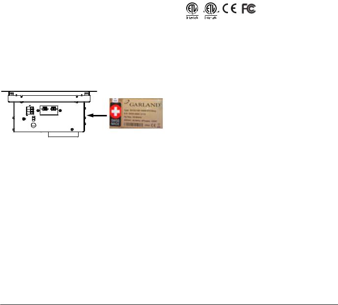
Serial Plate Location
The serial plate is affixed to the side of the housing, near the electrical connectors at the front. Important information such as the unit’s model number, serial number, and electrical specifications can be found on the serial plate.
Compliances
•North American models:
ETL recognized* in compliance with UL 197, CSA C22.2 No.109, NSF-4. Complies with FCC part 18, ICES-001
*see section “Installation” on page 11
•CE models comply with the latest European Norms: EN 60335-1, EN 60335-2-36, EN 62233 (EMC/EMV)
Part Number 4532285 1/15 |
9 |
THIS PAGE INTENTIONALLY LEFT BLANK
Section 2
Installation
nWarning
Safety and Electrical Requirements
This appliance component requires additional features and components to comply with appliance and electrical standards.
It is the responsibility of the customer and installer to interpret and comply with all applicable national and regional health codes, safety and electrical standards in your jurisdiction.
This product requires the addition of:
•A suitable non-flammable electrical enclosure; a means to conceal and protect components and wiring.
•Grounding and bonding to the enclosure.
•An appliance rating plate that includes end manufacturer information.
•Investigation by local electrical authority. Warning, caution labels and other markings required by electrical and safety standards could be provided by local authority.
Depending on the application and configuration of this product(s), consider the addition of:
•Field supply connection terminals (terminal block).
•Branch circuit protection (breakers).
•Fans, ventilation or cooling systems and controls.
nWarning
Installation must be carried out by registered installation contractors only. The contractors are responsible for interpreting all instructions correctly and performing the installation in compliance with national and local regulations. The warning signs and serial plates on the equipment must strictly be followed.
nWarning
The unit is designed for custom built counter or island suite. Customers are responsible to provide proper installation mounting for the components.
Read ALL SECTIONS carefully, comply with all requirements listed and ensure inspection is done by qualified personnel.
nWarning
To avoid instability the installation area must be capable of supporting the combined weight of the equipment and product.
The equipment must be level side to side and front to back.
nWarning
This equipment is intended for indoor use only. Do not install or operate this equipment in outdoor areas.
,Caution
This equipment must only be operated under an approved hood system in accordance with local regulations in force.
,Caution
Consultants and designers must consult their contertop suppliers when designing an appropriate support structure and clearance for the counter-top and installation.
Notic
Induction equipment that is not installed correctly will have warranty voided.
NOTE: Always maintain enough space between and around the equipment in the cabinet for maintenance and service.
Part Number 4532285 1/15 |
11 |
Installation |
Section 2 |
|
|
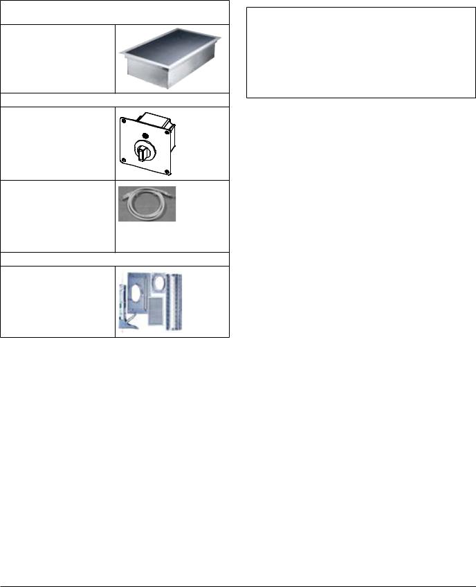
Components
Induction Generator, RTCSmp Built-In Line Dual Cook-Tops (with Built-In Frame and Ceran Glass-Top)
x1 7kW Unit (2x 3500Watts) or
x1 10kW Unit (2x 5000Watts)
Control Unit, Complete Assembly
x2, one for each cook zone
Included, two (2) RJ-45 Cables
Each RJ-45 cable is 914mm or 36 inches long.
Air Intake Kit for Built-In Dual Cook-Tops Unit
Kit Part Number 95000020 x1
Silicone sealant is provided in the kit for installation.
NOTE: Mains power supply cable not included.
Overview: Critical Information on Design and Installation
nWarning
The unit is designed for custom built counter or island suite. Customers are responsible to provide proper installation mounting for the components.
Read ALL SECTIONS carefully, comply with all requirements listed and ensure inspection is done by qualified personnel.
Typical Installation Procedure |
Component to Install |
Refer to the sections below for requirements |
|
|
|
Step |
Generator |
Operating Conditions, Electrical |
1 |
|
Compartment, Location and Ventilation |
|
|
Requirements: “Critical Requirements” on |
|
|
page 13 |
|
|
|
|
|
“Installation Clearance” on page 14 |
|
|
|
|
|
Weights, Dimensions and Installation |
|
|
Instructions: “Built-In SH/DU/IN Generator |
|
|
Installation” on page 17 |
|
|
|
Step |
Control |
“Installation Clearance – Components” on |
2 |
Units |
page 14 |
|
|
|
|
|
“Control Unit Installation” on page 19 |
|
|
|
Step |
Air Intake |
Components and Installation Instructions: |
3 |
Kit |
“Air Intake Kit (P/N 95000020)” on page 21 |
|
|
|
Step |
Electrical |
“Electrical compartment” on page 13 |
4 |
|
|
|
“Electrical Specifications” on page 22 |
|
|
|
|
|
|
|
|
|
“Electrical Installation” on page 22 |
|
|
|
Step |
Test |
“Function Test” on page 24 |
5 |
|
|
|
|
|
12 |
Part Number 4532285 1/15 |
Loading...