


SERVICE MANUAL FOR THE
MODELS: MP-GS/GD-10-S
Users are cautioned that maintenance and repairs must be performed by a Garland authorized service agent
using genuine Garland replacement parts. Garland will have no obligation with respect to any product that has been improperly installed, adjusted, operated or not maintained in accordance with national and local codes or installation instructions provided with the product, or any product that has its serial number defaced, obliterated or removed,
or which has been modified or repaired using unauthorized parts or by unauthorized service agents.
For a list of authorized service agents, please refer to the Garland web site at http://www.garland-group.com. The information contained herein, (including design and parts specifications), may be superseded and is subject to change without notice.
GARLAND COMMERCIAL INDUSTRIES |
GARLAND COMMERCIAL RANGES, LTD. |
Enodis UK LTD. |
185 East South Street |
1177 Kamato Road, Mississauga, Ontario L4W 1X4 |
Swallowfield Way, Hayes, Middlesex UB3 1DQ ENGLAND |
Freeland, Pennsylvania 18224 |
CANADA |
Telephone: 081-561-0433 |
Phone: (570) 636-1000 |
Phone: 905-624-0260 |
Fax: 081-848-0041 |
Fax: (570) 636-3903 |
Fax: 905-624-5669 |
|
Part # MPSM07 (03/24/08) |
© 2007 Garland Commercial Industries, Inc. |
Page |
Part # MPSM07 (03/24/08) |

TABLE OF CONTENTS
Section One – |
|
Section Two – Service . . . . . . . . . . . . . . . . |
39 |
|
Operation & Installation Manual . . . . . . |
.5 |
Component Identification . . . . . . . . . . . . . . . . . . |
.40 |
|
Dimensions And Specifications . . . . . . . . . . . . . . . |
. 7 |
Moisture Control . . . . . . . . . . . . . . . . . . . . . . . . |
. 40 |
|
Preparing The Oven For Installation . . . . . . . . . . |
. 8 |
Cavity Temperature Controls . . . . . . . . . . . . . |
. 41 |
|
Installation . . . . . . . . . . . . . . . . . . . . . . . . . . . . . . . . . . |
11 |
Diagnostic Procedures . . . . . . . . . . . . . . . . . . . . . . |
. 43 |
|
Gas Connections . . . . . . . . . . . . . . . . . . . . . . . . . . . . |
11 |
Diagnostics Mode . . . . . . . . . . . . . . . . . . . . . . . |
. 43 |
|
Electrical Connections . . . . . . . . . . . . . . . . . . . . . . . |
12 |
Keypad Test . . . . . . . . . . . . . . . . . . . . . . . . . . . . . |
. 43 |
|
Water Connections . . . . . . . . . . . . . . . . . . . . . . . . . . |
13 |
Door Switch Test . . . . . . . . . . . . . . . . . . . . . . . . |
. 43 |
|
Ventilation And Air Supply . . . . . . . . . . . . . . . . . . . |
14 |
Fan Speed Test . . . . . . . . . . . . . . . . . . . . . . . . . . |
.44 |
|
Installation Of A Direct Vent . . . . . . . . . . . . . . . . . . |
14 |
Heat Test . . . . . . . . . . . . . . . . . . . . . . . . . . . . . . . . |
.44 |
|
Gas Model Testing & Lighting Instructions . . . . |
15 |
Moisture Test. . . . . . . . . . . . . . . . . . . . . . . . . . . . |
.44 |
|
Explanation Of Controls (Standard Models) . . . |
16 |
Temperature Calibration . . . . . . . . . . . . . . . . . |
.44 |
|
Operating Instructions, (Standard Models) . . . . |
17 |
Control Safety Features . . . . . . . . . . . . . . . . . . |
.44 |
|
Explanation Of Controls, (Deluxe Models) . . . . . |
18 |
Testing & Troubleshooting . . . . . . . . . . . . . . . . . . |
.46 |
|
Operating Instructions, (Deluxe Models) . . . . . . |
20 |
Direct Spark Ignition Detail . . . . . . . . . . . . . . |
. 54 |
|
Cooking With Moisture . . . . . . . . . . . . . . . . . . . . . . |
29 |
Wiring Diagrams . . . . . . . . . . . . . . . . . . . . . . . . . . . |
. 55 |
|
Moisture + Cooking Guide . . . . . . . . . . . . . . . . . . . |
30 |
Service Procedures (Removal/replacement) . . |
. 57 |
|
Performance Recommendations . . . . . . . . . . . . . |
32 |
Section Three – Parts List . . . . . . . . . . . . . |
61 |
|
Temperature Calibration . . . . . . . . . . . . . . . . . . . . . |
33 |
Deluxe Control Panel Moisture Plus (Gas) |
62 |
|
Problems / Solutions |
34 |
|||
Standard Control Panel Moisture Plus (Gas) |
64 |
|||
Cleaning |
35 |
|||
Burners & Gas Components |
66 |
|||
Maintenance |
36 |
|||
Interior Components Moisture Plus (Gas) . . . . . 68 |
||||
Motor Care |
36 |
|||
Door Components - Gas Moisture + |
70 |
|||
Water System |
36 |
|||
Door Components - Gas Moisture + |
72 |
|||
Replacement Parts |
37 |
|||
Exterior Components - Gas Moisture Plus |
74 |
|||
|
|
|||
|
|
Wire Diagrams & Harnesses . . . . . . . . . . . . . . . . . . . . . . |
.76 |
|
Part # MPSM07 (03/24/08) |
Page |
Page |
Part # MPSM07 (03/24/08) |
Section One –
Operation &
Installation Manual
Part # MPSM07 (03/24/08) |
Page 5 |
Congratulations! You have just purchased the latest in cooking technology, the new moisture+™ from Garland.
Garland is an established leader in innovative oven technology, and has manufactured this multifunction oven with the operator in mind. The moisture+™ provides function not previously available in a convection oven. Your moisture+™ will operate as three pieces of equipment: a convection oven, a humidified baking oven, and a humidified cook & hold oven. Additionally, the optional wet-clean water spray attachment allows you to easily spray down the oven interior during cleaning. Garland, long known for offering the “best baking” convection ovens available, adds the moisture+ to its model line to provide you, the user with, a workhorse oven that will provide years of useful service.
Like any other fine, precision built appliance, your moisture+™ oven should be given regular care and maintenance. Periodic inspection by your dealer or a qualified service agency is recommended. When corresponding with the factory or your local authorized factory service center regarding service problems or replacement parts, be sure to refer to the particular oven by the correct model number, (including the prefix/suffix letters and numbers), and the warranty serial number. The rating plate affixed to the oven contains this information.
Page 6 |
Part # MPSM07 (03/24/08) |
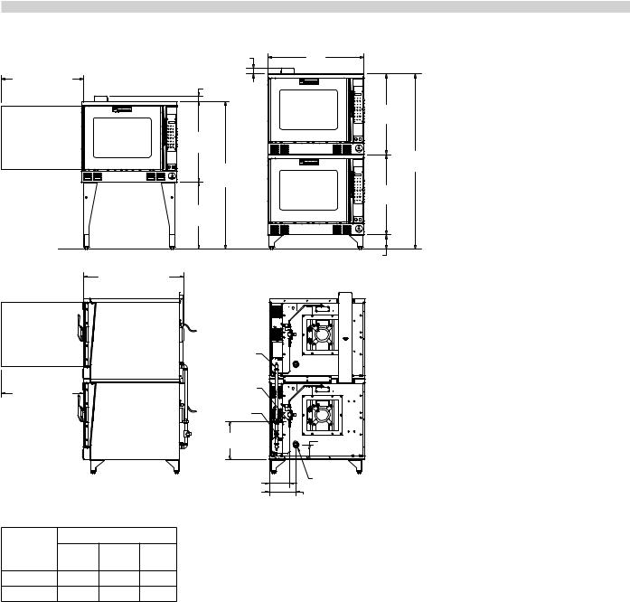
DIMENSIONS AND SPECIFICATIONS
|
|
|
2-1/4" |
|
32-3/4" |
|
|
[57mm] |
|
|
|
|
||
[832mm] |
|
|
2-1/4" |
|
DOOR OPENING |
|
|||
|
[57mm] |
|||
REQUIRED |
|
|
||
|
|
|
||
|
|
|
32" |
|
|
|
|
[813mm] |
|
|
|
|
58.5" |
|
|
|
|
[1486mm] |
|
|
|
|
26-1/2" |
|
|
|
|
[673mm] |
|
FLOOR |
|
|
|
|
LINE |
|
|
|
|
|
|
40" [1015mm] |
||
|
|
ADD 4" [102mm] |
||
|
|
FOR DEEP OVENS |
||
|
|
|
SINGLE DECK |
|
|
|
|
GAS SUPPLY |
|
|
|
|
3/4" NPT |
|
|
|
|
1/8" NPT |
|
32-3/4" |
|
|
WATER SUPPLY |
|
[832mm] |
|
|
DOUBLE STACK |
|
DOOR OPENING |
|
|||
REQUIRED |
|
|
GAS SUPPLY |
|
|
|
|
1" NPT |
|
|
|
|
15" |
|
|
|
|
[381mm] |
|
|
|
|
8-1/4" |
|
|
|
|
[210mm] |
|
Gas |
Input Ratings |
|||
Gas |
BTU |
|
||
Models |
kW |
|||
Inlet |
Hour |
|||
|
|
|||
Natural |
¾” NPT |
80,000 |
23..5 |
|
Propane |
¾” NPT |
60,000 |
17..6 |
|
38"
[965mm]
32"
[813mm]
70-1/4" [1784mm]
32"
[813mm]
6-1/4" [159mm]
5-1/2"  [140mm]
1-1/2" NPT
DRAIN CONNECTION
10-1/2" [267mm]
Notes:
1.Standard electrical specifications include motor requirements
2.All ovens have a ¾ HP, two speed motor; 1140 and 1725 RPM, 60 Hz
3.Garland recommends that a separate 15 Amp circuit be provided for each 120V oven
4.A 6 foot line cord is provided for each 120V oven with a NEMA 5-15P plug..
5.Double stack installations require an individual power supply connection to each oven..
Gas input ratings are for installations up to 2000 feet (610 m) above sea level.. Specify altitudes above 2000 feet..
Commercial cooking equipment requires an adequate ventilation system.. For additional information refer to the National Fire Protection Associations standard NFPA96, “Vapors Removal from Cooking Equipment” (Note: For North America only)
|
|
|
Input Ratings |
|
|
|
|
|
|
|
|
|
Nominal Amperes |
|
|
|
|
|
||||||
Electric |
|
|
|
Total KW/Line |
120V |
208V |
240 V |
460V |
|
208V 3 Ph |
|
240V 3 Ph |
|
460V 3 Ph |
|
|
||||||||
kW |
|
208/240/460 |
|
|
|
|
||||||||||||||||||
Models |
|
|
1Ph |
1 Ph |
1 Ph |
1 ph |
|
|
|
|
|
|
|
|
|
|
|
|||||||
|
|
|
X-Y |
Y-Z |
X-Z |
|
|
X/Y/Z |
|
X/Y/Z |
|
X/Y/Z |
|
|
||||||||||
|
11 |
|
3..33 |
3..33 |
4..33 |
N/A |
53 |
46 |
24 |
|
31..8/27..7/31..8 |
27..6/24..0/27..6 |
10..5/9..5/10..5 |
|
|
|
||||||||
|
|
|
|
|
|
|
|
|
|
|
|
|
|
|
|
|
|
|||||||
Model |
|
|
Description |
|
|
Interior Dimensions: in [mm] |
|
Exterior Dimensions: in [mm] |
|
Weight |
Size |
|||||||||||||
|
|
|
|
|
W |
|
|
H |
D |
|
|
W |
|
H |
|
D |
|
(lbs/kg) |
(Cu ft) |
|||||
|
|
|
|
|
|
|
|
|
|
|
|
|
|
|
|
|||||||||
MP-ES/GS-10-S |
|
Std Depth, |
|
|
|
|
|
|
|
|
|
|
|
|
|
60-3/4 [1543] |
|
|
|
510/232 |
42 |
|||
|
|
Sgl Deck |
|
|
|
|
|
|
|
|
|
|
|
|
|
|
|
|
||||||
|
|
|
|
|
|
|
|
|
|
|
24 [610] |
|
|
|
|
|
40 [1016] |
|
|
|
||||
MP-ES/GS-20-S |
|
Std Depth, |
|
|
|
|
|
|
|
|
|
|
72-1/2 [1842] |
|
|
1024/464 |
84 |
|||||||
|
|
|
|
|
|
|
|
|
|
|
|
|
|
|
|
|
||||||||
|
|
Dbl Deck |
|
|
|
|
|
|
|
|
|
|
|
|
|
|
|
|
||||||
|
|
|
|
|
|
29 [736] |
|
24 [610] |
|
|
|
|
38 [965] |
|
|
|
|
|
|
|
||||
MP-ED/GD-10-S |
|
Deep Depth, |
|
|
|
|
|
|
|
|
60-3/4 [1543] |
|
|
|
510/232 |
42 |
||||||||
|
|
|
|
|
|
|
|
|
|
|
|
|
|
|
|
|
||||||||
|
|
|
|
Sgl Deck |
|
|
|
|
|
|
|
28 [711] |
|
|
|
|
|
44 [1118] |
|
|
|
|||
MP-ED/GD-20-S |
|
Deep Depth, |
|
|
|
|
|
|
|
|
|
|
72-1/2 [1842] |
|
|
1024/464 |
84 |
|||||||
|
|
|
|
|
|
|
|
|
|
|
|
|
|
|
|
|
||||||||
|
|
|
|
Dbl Deck |
|
|
|
|
|
|
|
|
|
|
|
|
|
|
|
|
|
|
|
|
Part # MPSM07 (03/24/08) |
Page |
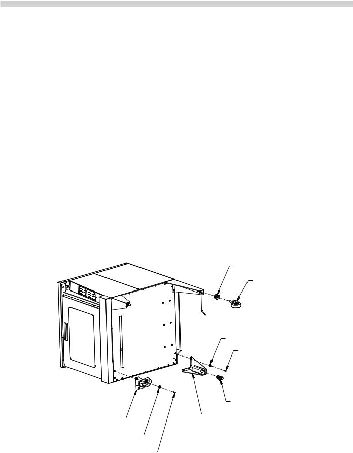
PREPARING THE OVEN FOR INSTALLATION
Legs and Casters
NOTE: If you will be installing an open base kit, please skip to the next page and proceed with the steps listed under “Open Base Assembly..”
1.(See Figure 1..).. At the bottom end of each leg, install the bullet foot insert or caster insert.. The fit of the insert to the leg is intended to be snug, tap them lightly into place with a mallet or rubber hammer..
Install two #5 x 1/4” self-drilling, thread forming screws into each caster insert..
2.Screw a caster into the insert on each of the four legs.. The caster must be inserted at least three full threads to properly support the oven.. A 1” (25mm) open-end wrench may be needed to properly install the casters..
OR
Using your fingers, screw the ends of the bullet feet into the leg clockwise until they are at their shortest length..
3.Carefully tip and lower the oven onto its left side so you can easily reach the bolt mounting locations in the base..
4.The four holes in the top of each leg or in the top plate of double stack casters will match the bolt locations at each corner of the oven base..
You will need four 3/8-16 x 1” hex head bolts and four 3/8” flat washers to mount each leg.. Align the leg to one of the matching bolt holes on the base and insert a bolt with washer..
Install the remaining three bolts and finger-tighten all four before using an 11/16” wrench to fully tighten them all.. Be sure to tighten all four bolts for each leg or caster.. When installing casters, make sure the two casters with brakes are installed at the front of the oven..
5.Carefully return the oven to an upright position.. Ensure the two legs/casters that touch the floor first when you raise the oven are blocked and chocked so they do not slip away..
6.It is very important to use the adjustable bullet foot inserts in leveling the unit.
7.If you have installed casters, be sure to install the restraint bracket on the lower left corner of the rear of the oven using two #10 x 3/4” sheet metal screws..
DOUBLE DECK CASTER (4)
FLAT WASHER (4 EACH CASTER)
BOLT (4 EACH CASTER)
CASTER INSERT (4)
CASTER (4)
 SCREW (2 PER CASTER INSERT)
FLAT WASHER (4 EACH LEG)
BOLT (4 EACH LEG)
FOOT INSERT (4)
LEG ASSEMBLY (4)
Figure 1.
Page |
Part # MPSM07 (03/24/08) |
PREPARING THE OVEN FOR INSTALLATION
Open Base Assembly
Use the following sequence of steps to assemble and install the open base accessory..
1.(See Figure 2..).. Align the rack guide upper support to the corresponding holes in the oven base.. Fasten using three #10 x 3/4” machine screws on each side of the oven..
2.At the lower end of each leg install an “L” shaped support clip using a #10 x 3/4” sheet metal screw.. Do this before fastening the leg to the base..
3.Install legs to the bolt holes at the front and rear of the base on the oven’s left side, (side lying on the floor).. If installing casters, be sure to install a locking caster on the front leg.. Refer to the section, “Legs and Casters,” on the previous page for installation details..
4.Fasten the open base panel in place on the brackets of the two legs already installed, using one #10 x 3/4” sheet metal screw in each corner..
5.While supporting the open base panel, install the rightside legs as in step 2.. Ensure the caster with a brake is at the front of the oven.. Fasten the remaining two corners of the open base panel to the other two legs just installed..
6.Carefully return the oven to an upright position.. Ensure the two legs/casters that touch the floor first when you raise the oven are blocked and chocked so they do not slip away..
7.Install the rack guides in one of the two available positions.. The inner position sets the guides at a width to accommodate oven pans.. The outer position sets the guides at a width to accommodate wire oven racks.. To
attach, insert the longer straight end at the top of the rack guide all the way into the mounting hole, then align the bottom holes and lower the rack guide into position..
8.It is very important to use the adjustable bullet foot inserts in leveling the unit.
9.If you have installed casters, be sure to install the restraint bracket on the lower left corner of the rear of the oven using two #10 x 3/4” sheet metal screws..
RACK GUIDE UPPER SUPPORT
RACK GUIDE (2)
SCRREW (2 EACH CLIP) SCREW (1 EACH CLIP)
OPEN BASE UPPORT CLIP (4)
LEG ASSEMBLY (4)
W/FOOT INSERT
INNER
OUTER
INNER GUIDE POSITION
FOR TRAYS
|
OUTER GUIDE POSITION |
SCREW (6x) |
FOR RACKS |
|
|
|
OPEN BASE PANEL |
Figure 2.
Part # MPSM07 (03/24/08) |
Page |

PREPARING THE OVEN FOR INSTALLATION
Stacking Two Ovens
1.Follow the instructions in the section entitled, “Legs and Casters,” on page 5.. Then resume at step 2 on this page to complete the stacking process..
2.Move the lower oven as close to the final installation point as possible, leaving enough space around the oven to allow access for the remaining installation steps.. If casters have been installed, apply the brakes on the two front wheels..
3.Carefully raise the upper oven and place it on top of the lower oven, aligning the four lower corners of the upper even to the four upper corners of the lower oven..
4.At the rear of the stacked ovens, install the stacking bracket using six 1/4-20 x 1” hex head bolts with lock washers and nuts.. Firmly tighten all six nuts/bolts to secure the ovens together..
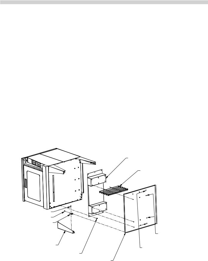
5.Remove the outer flue vent from the right top corner of the rear of each oven, saving the screws..
6.If they are not already fastened together, assemble the two parts of the interconnecting flue channel included in the stacking kit, using six #10 x 3/4” sheet metal screws..
7.Fit the channel assembly over the flue vent area of each oven and fasten using the screws removed in step 5..
8.If you have installed casters, be sure to install the restraint bracket on the lower left corner of the rear of the upper oven using two #10 x3/4” sheet metal screws..
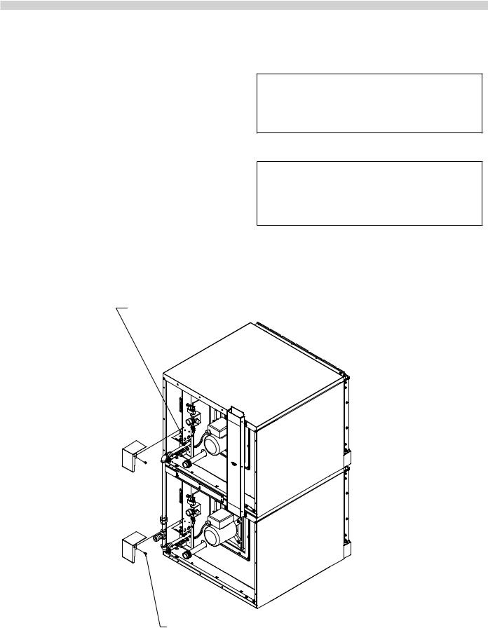
9.If your installation requires one common gas inlet for both ovens, use the piping included with your stacking kit to assemble the interconnecting gas pipe.. Refer to Figure 3..
NOTE: It is recommended, when stacking a Moisture + Oven with a Master Convention Oven, that the Moisture + be located on the bottom..
|
|
|
Item Reference Key For Figure 3 |
|
|
|
|
Item |
Item Description |
|
|
|
No.. |
|
|
|
|
|
|
|
|
|
1 |
MSCR-HH STL 1/4-20x3/4 |
|
|
|
2 |
LKSHR-SPL 1/4x1/2x1/6 |
|
7 |
|
3 |
Nut - Hex 1/4-20 STL ZP |
|
|
4 |
Bell Reducer 1” x 3/4” |
|
|
|
|
||
|
|
|
5 |
3/4 Tee NPT |
|
|
|
7 |
Flue Assembly – Double Stack |
|
|
|
8 |
Pipe Union 3/4 NPT |
9 |
3 |
|
10 |
Close Nipple 3/4 x 1 |
|
|
|||
|
2 |
|
11 |
Pipe 3/4 x 20-1/2” |
13 |
|
1 |
12 |
3/4 x 3-1/2 Nipple |
|
14 |
13 |
Bell Reducer |
|
11 |
|
|||
8 |
|
|
14 |
Stacking Bracket Rear |
|
|
|
|
|
5 |
12 |
|
12 |
||
4 |
||
|
||
13 |
9 |
Figure 3..
Page 10 |
Part # MPSM07 (03/24/08) |
INSTALLATION
It is the responsibility of the purchaser to ensure the oven is installed in a manner to meet all local codes.. In the absence of local codes, applicable national codes are referenced in this booklet.. In the case of discrepancy between the information in this booklet and local codes, it is recommended you consult your local inspector(s).. This appliance meets or exceeds all applicable regulations and standards in effect on its date of manufacture..
Location
The importance of the proper installation of Commercial Gas Cooking Equipment cannot be over stressed.. Proper performance of the equipment is dependent, in great part, on the compliance of the installation with the manufacturer’s specifications.. Installation must conform to local codes or, in the absence of local codes, with the National Fuel Code, ANSI
Z223..1, Natural Gas Installation Code, CAN/CGA-B149..1, or the Propane Installation Code, CAN/CGA-B149..2, as applicable..
Wall Clearance
This oven, single or stacked, must be installed with adequate clearance to combustible and non-combustible walls..
Sides: |
1 inch [25 mm] |
Back: |
3 inches [76 mm] for gas ovens, and |
|
6 inches [152 mm] for electric ovens.. |
Garland recommends that a one inch clearance be maintained between this oven and any other cooking appliance..
Garland recommends that this oven not be installed with a broiler or open burner appliance immediately adjacent to the right side..
Each appliance shall be located with respect to building construction and other equipment so as to permit access to the appliance.. Such access and clearance may be necessary for servicing and cleaning..
GAS CONNECTIONS
The type of gas for which the oven is equipped is stamped on the data rating plate.. It is located inside the lower front trim cover.. Connect an oven stamped “NAT” to natural gas only.. Connect an oven stamped “PRO” to propane gas only..
If the oven is being installed into a new location, have gas authorities check the meter size and piping to assure the supply line has a sufficient amount of gas pressure to operate the oven..
If the oven is a replacement or additional appliance to an existing installation have gas authorities check the pressure to ensure the existing meter and pressure will supply the oven with no more than a 1/2” water column pressure drop..
Note: When checking the gas pressure make sure all other appliances on the same gas line are turned on..
A pressure regulator is supplied with Garland convection ovens.. The regulator pressure is preset to deliver the gas at the pressure shown on the rating plate.. Do not install an additional regulator where the unit connects to the gas supply unless the gas pressure exceeds the maximum recommended pressure..
The oven and its individual shut-off valve must be disconnected from the gas supply piping system during any pressure testing of that system at test pressures in excess of 1/2 PSI (3..45 kPa)..
The oven must be isolated from the gas supply piping system by closing its individual manual shut-off valve during any pressure testing of the supply system at test pressures equal to or less than1/2 PSI (3..45 kPa)..
Part # MPSM07 (03/24/08)
Prior to connecting to the building gas supply the lines should be purged of all metal filings, pipe thread compound or other debris..
The gas connection piping (3/4” for single ovens, 1” for stacked ovens), must be considered when planning the supply line.. Undersized gas supply lines may restrict the gas flow and affect performance.. If other gas appliances are supplied by the same supply line, it must be sized to carry
the combined volume required for all the appliances without causing a more than 1/2” pressure drop at the manifold of each appliance on line at full rate..
Recommended supply pressures are 7” ± 5% WC for natural gas (NAT) and 11” ± 5% WC for propane (PRO).. The inlet pressure for the supply line must not exceed 13..8”WC natural and 15”WC for propane..
Two ovens stacked may be supplied by a single gas line.. The minimum recommended size of a single supply line for two stacked ovens is 1 inch..
Assemble the gas pipes and fittings provided in the stacking kit as shown in the Figure 3 on page 7.. Use a pipe thread compound that is intended for use on propane gas piping..
Be sure to check for leaks before finalizing the installation.. Use appropriate solutions or detection devices..
Installations in which a flexible gas connection hose is used, require the supplied strain relief to be installed at the lower left rear corner of the base.. Install the strain relief in
accordance with applicable codes.. The strain relief must limit the movement of the oven to prevent unnecessary stress on the flexible connector..
Page 11
ELECTRICAL CONNECTIONS
A separate electrical connection must be supplied for each oven.. Connection to the electrical service must be grounded in accordance with local codes, or in the absence of local codes with the National Electrical Code, ANSI/NFPA 70, or the Canadian Electrical Code, CSA C22..2, as applicable..
A strain relief for the power supply cord is required.. The installer must supply a cord bushing that meets local and national codes..
For 120VAC usage a cord and NEMA 5-15P plug is provided.. Garland recommends a separate 15 Amp service for each oven.. Ovens for 120V service are supplied with a three pronged plug for your protection against shock hazard and should be plugged directly into a properly grounded threeprong receptacle..
DO NOT CUT OR REMOVE THE GROUNDING PRONG FROM THE PLUG.
A wiring diagram is affixed to the rear of the oven and included in this booklet..
CAUTION:
DISCONNECT ALL OVENS FROM ELECTRI-
CAL SUPPLY BEFORE
SERVICING..
POWER FAILURE:
IN THE EVENT OF A POWER
FAILURE, NO ATTEMPT SHOULD BE MADE
TO OPERATE THIS OVEN..
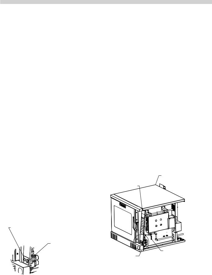
Figure 4..
ELECTRIC OVENS - SHIPPED WITH KNOCKOUT PLATE FOR POWER SUPPLY
REMOVE THIS SCREW TO ALLOW
ACCESS TO THE TERMINAL BLOCK (ELECTRIC OVENS) OR CORD CONNECTIONS (GAS OVENS)
Page 12 |
Part # MPSM07 (03/24/08) |
WATER CONNECTIONS
It is the responsibility of the purchaser to install and maintain the water supply to the moisture+ oven.. Failure to provide satisfactory water quality to operate the oven properly
can cause damage to integral components and void your warranty..
This oven must be installed to comply with the applicable federal, state, or local plumbing codes..
Water supply connection to the moisture+ is made via a 1/8” NPTF fitting at the rear of the oven.. The ability to move the oven for service and cleaning may be a consideration when choosing the type of connection and supply line to be attached at this fitting..
The moisture+ water delivery system includes a water pressure regulator that has been pre-set to operate at 20 psi.. The water supply must maintain at least 20 psi and a flow rate of three gallons per minute for proper operation of the oven’s moisture injection system..
Water Quality Requirements
Garland recommends that the supply water be filtered before it enters the oven’s water delivery system.. This will extend the life of the oven and its water delivery system components by minimizing particles in typical tap water sources that cause scaling and build-up of mineral deposits..
The recommended minimum water quality standards, whether treated or pre-treated, and based on 10 hours of use per day, and daily cleaning../descaleing are as follows:
Total dissolved solids – less than 60 parts per million, total alkalinity – less than 20 parts per million, silica – less than 13 parts per million, chlorine – less than 30 parts per million and a pH Factor greater than 7..5..
Consult a local water treatment specialist for an on-site water analysis for recommendations concerning feed water treatment (if required), in order to remove or reduce harmful concentrations of minerals.. The use of highly mineralized water will cause more frequent cleaning and reduce operating efficiency.. The fact that a water supply is potable is not proof that it will be suitable for moisture mode operation.. Component failure/service related to poor water quality will not be covered under warranty..
Spray/Flex Hose W/Quick Disconnect
Your moisture+ oven may be equipped with the optional spray/flex hose assembly.. The spray/flex hose assembly is intended to assist in cleaning the oven.. The water pressure and velocity may vary, depending on the pressure and velocity of the water supply connected to the oven..
Drain
Your moisture+ oven has a gravity drain in the right rear corner of the oven cavity.. The drain pipe that exits the rear of the oven must be directed downward toward the floor, and should run directly to an open floor drain.. Garland provides an 1-1/2” male pipe adapter for connecting your drain lines.. Avoid using flexible hose that could sag or kink, allowing water to accumulate.. The drain must be vented.. This connection must be at least 1-1/2” (38..1 mm) in diameter and configured in accordance with local codes..
1/8" NPT WATER SUPPLY CONNECTION
A
DETAIL A
|
1-1/2" NPT MALE |
B |
|
DETAIL B |
TRAP ADAPTER |
||
|
|||
|
|
Figure 5.
Part # MPSM07 (03/24/08) |
Page 13 |
VENTILATION AND AIR SUPPLY
Proper ventilation is highly important for effective operation.. There are only two choices for properly venting an oven:
1) canopy hood, or, 2) direct venting.. The ideal method of venting a gas oven is through the use of a properly designed canopy hood.. The hood should extend beyond all sides of the oven 6 inches, (150 mm), and be installed at least 78 inches, (1950mm), from the floor..
A strong exhaust fan will create a vacuum in the room.. For exhaust system vents to work properly, exhaust and make-up air must be balanced.. For proper air balance, contact your local H..V..A..C.. contractor..
All gas burners and pilots need sufficient air to operate and large objects should not be placed in the rear or at the bottom of this oven which would obstruct the airflow
through the front covers.. Do not place objects over the oven vent exit..
Some localities require an electric oven to be installed under an exhaust hood.. Be sure to consult your local code inspector prior to operating any gas or electric oven..
IMPORTANT
ALL GAS BURNERS AND PILOTS NEED SUFFICIENT AIR TO OPERATE AND LARGE OBJECTS SHOULD NOT BE PLACED IN FRONT OF THIS OVEN, WHICH COULD OBSTRUCT THE AIRFLOW THROUGH THE FRONT.. OBJECTS SHOULD NOT BE PLACED ON MAIN TOP REAR OF THE OVEN WHILE IN USE.. THIS COULD OBSTRUCT THE VENTING SYSTEM OF THE OVEN’S FLUE PRODUCTS..
INSTALLATION OF A DIRECT VENT
When the installation of a canopy hood is impossible, the oven may be direct vented.. Before direct venting check you local codes on ventilation, in the absence of local codes refer to the National Fuel Code NFPA 54, ANSI Z223..1 (latest revision)..
If the oven is to be connected to a direct flue vent, it is necessary that a draft diverter be installed to ensure proper ventilation..
The draft diverter should be positioned on the main top of the oven and fastened with sheet metal screws provided.. All parts described above are available from the manufacturer..
Note: Each oven has been factory tested and adjusted prior to shipment.. It may be necessary to further adjust the oven as part of a proper installation.. Such adjustments are the responsibility of the installer.. Adjustments cannot be
considered defects in material or workmanship and they are not covered under the original equipment warranty..
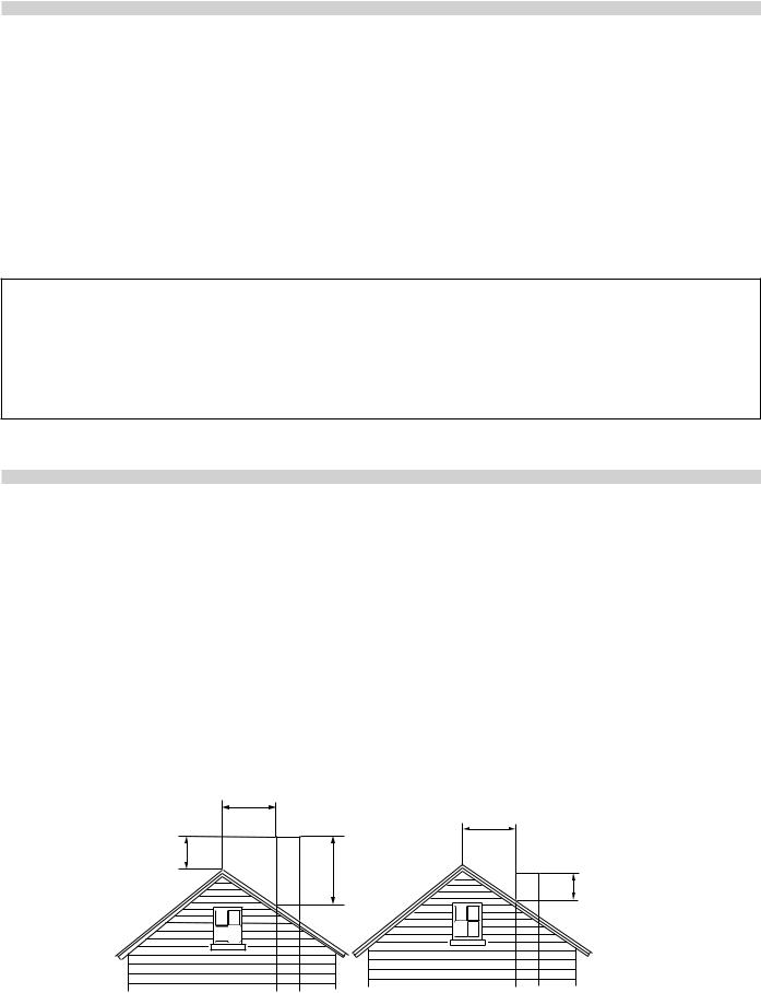
DO NOT UNDERSIZE THE VENT PIPE! This can cause resistance to flow and impede good venting.. We suggest that if a horizontal run must be used it should rise no less than 1/4” (6..25mm) for each linear foot of run, and after a total of 180° of bends you should increase the size of stove pipe by 2”.. The flue should rise 2’ (60 cm) to 3’ (90 cm) above the roofline or 2’ (60cm) to 3’ (90cm) above any portion of a building within a horizontal distance of 10’ (3 m)..
Less than 10 feet (3 meters)
|
More than 10' (3 meters) |
2' (60cm) Min. |
|
3' (90cm) Min. |
|
|
3' (90cm) Min. |
Termination Less than 10 feet (3 meters) from ridge |
Termination More than 10 feet (3 meters) from ridge |
Figure 6 .
Page 14 |
Part # MPSM07 (03/24/08) |
GAS MODEL TESTING & LIGHTING INSTRUCTIONS
Turn on the main gas valve..
Remove the lower front trim cover.. Drop the control panel and leak test all fittings and connections upstream from the service valve located on the redundant combination gas valve.. Should any gas leaks be detected turn OFF the main gas valve, correct the problem and begin the test again..
Remove the blanking plug from the manifold test spigot and connect a pressure test gauge..
Open the manual gas valve located behind the redundant combination gas valve..
Activate the control panel and set the oven to the desired temperature.. The burner will now ignite..
During installation there will be air in the gas line.. This air will have to bleed off before ignition can occur.. Wait five minutes after each attempt to bleed the air from the lines..
Turn on all appliances supplied by the same gas line and verify that the manifold pressure is 4..5”WC for natural gas or 10”WC for propane gas..
After the correct pressure has been verified, turn off the oven and remove the pressure gauge from the manifold pressure test spigot.. Re-install the blanking plug..
Check all fittings again.. Correct any leaks and begin the test again..
Replace all control panels, service panels and covers before operation..
All electronic ignition systems are supplied with a redundant gas valve.. Therefore, the oven is not supplied with an external pressure regulator..
To Conserve Energy:
Do not waste energy by leaving the controls at high temperature settings during idle periods.. Lower settings will keep the oven warm and ready for the next use period..
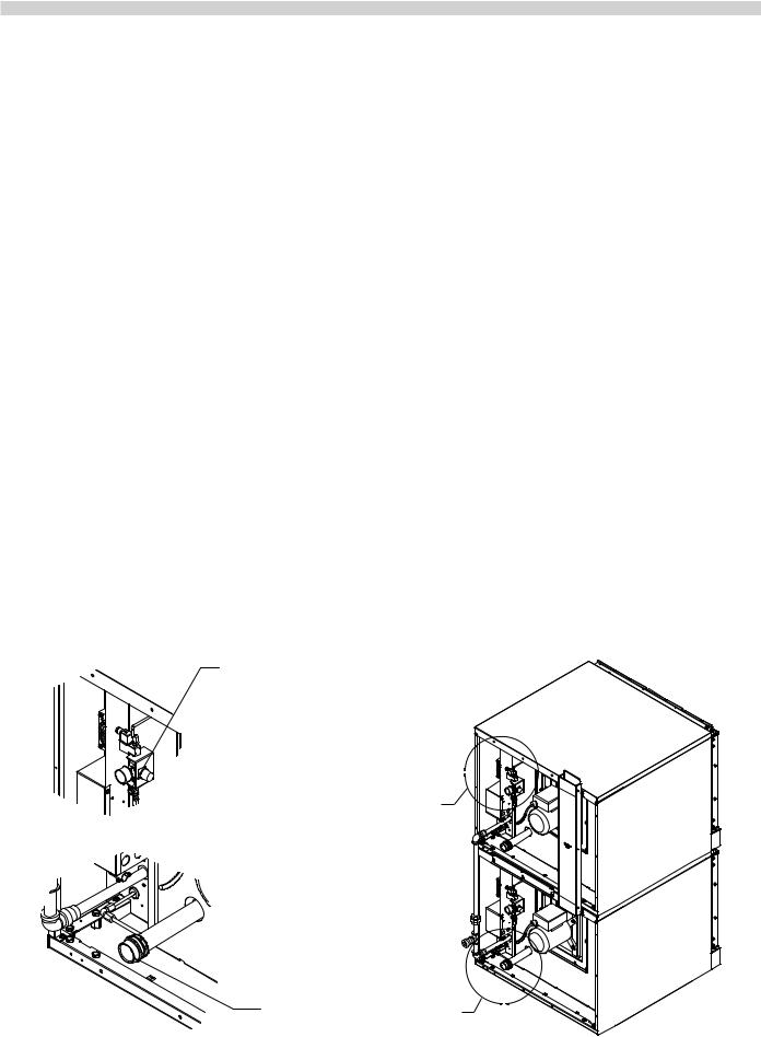
TO ACCESS THE MANUAL SHUTOFF,
REMOVE THE THUMBSCREW FROM
THE CONTROL PANEL, UNPLUG
THE CONTROL FROM THE WIRING HARNESS,
AND REMOVE THE CONTROL PANEL TO
EXPOSE THE MANUAL SHUTOFF VALVE.
REMOVE PLUG BUTTON TO
ACCESS PRESSURE ADJUSTMENT
FOR THE MANIFOLD
A
SAFETY SHUTOFF
SWITCH
FOR GAS VALVE
A
*** VIEW SHOWN WITHOUT THE BODY SIDE
FOR CLARITY***
3/4” MANUAL GAS VALVE
DETAIL A |
Figure 7. |
Part # MPSM07 (03/24/08) |
Page 15 |
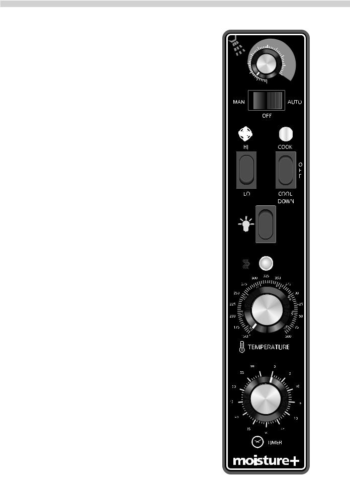
EXPLANATION OF CONTROLS (Standard Models)
Mechanical Control, (Standard Models)
Moisture Control
This controls the duration of the moisture injection into the oven cavity.. This is a rotary dial..
Moisture Switch
This rocker switch has three positions.. The center position is OFF.. This shuts off electrical power to the moisture system.. The AUTO position energizes the system until the switch is turned off.. This activates the injecting timer at the intervals manually set with the moisture control.. The MANUAL position is momentary.. Pressing will cause the moisture injector to inject moisture..
Fan Speed Switch
The left rocker switch, the fan speed switch, has two positions.. The motor and fan can be run at either high speed, (1725 RPM), by pressing the switch upward to HI, or low speed, (1140 RPM), by pressing the switch downward to LO..
Power Switch
The right rocker switch.. This main control switch has three positions.. The center position is OFF.. This shuts off electrical power to all functional components.. The COOK position energizes the timer, thermostat and moisture functions.. The COOL DOWN position energizes the motor and fan only..
Light Switch
This switch activates the oven interior light.. This is a momentary switch.. The light will stay lit as long as this button is held in the on position.. The light will operate in any mode, whenever there is electrical power connected to the oven..
Temperature
The temperature range is from 150°F, (66°C), to 500°F, (260°C).. Temperature is controlled by aligning the indicator to the desired temperature..
Timer
The timer is set by rotating the dial clockwise aligning the indicator to the desired time cycle.. At the end of the timing cycle, a buzzer will sound.. The buzzer is turned off by rotating the dial counterclockwise to the OFF position.. The buzzer will sound continuously until manually turned off..
40
|
35 |
45 |
|
|
|
30 |
|
50 |
|
|
|
25 |
|
55 |
|
|
|
20 |
|
60 |
|
|
|
|
15 |
LOW |
|
|
Page 16 |
Part # MPSM07 (03/24/08) |

OPERATING INSTRUCTIONS, (Standard Models)
In Off Mode
When the oven is off, there are no lights or indicators.. The oven interior light will operate..
Start Up
Press the Cook/Off/Cool Down rocker switch to the COOK position.. The green lamp will light indicating the oven is powered in cook mode..
The oven will begin to heat to the temperature set on the thermostat dial.. The amber lamp will light indicating the heat is active.. As the heat cycles on and off to maintain the set temperature this light will go on and off accordingly..
Garland “safe door” feature will be operational.. The door must be closed tightly for the oven to operate in cook mode..
Fan Speed
The fan speed can be either high, (1725 RPM), or low, (1140 RPM).. The fan speed is controlled by the left rocker switch positions marked HI and LO..
Interior Light
The oven interior light is activated by pressing the light switch.. This is a momentary switch.. The light will stay lit as long as this button is held in the on position.. The light will operate in any mode, whenever there is electrical power connected to the oven..
Cool Down
Pressing the Cook/Off/CoolDown rocker switch to the COOLDOWN position activates the fan and motor to cool the oven cavity.. The door must be open slightly for the fan and motor to start.. Heat is not active in this mode..
Optimal cool down will be achieved with the door open slightly ..If the door is opened too wide the motor and fan will shut off.. This is a safety feature.. When the door is partially closed again the motor and fan will operate..
Cool down will continue to operate until the control is changed.. Pressing the rocker switch to the OFF position cancels Cool Down and turns the oven off..
Temperature
The temperature range is from 150°F, (66°C), to 500°F, (250°C).. Temperature is controlled by aligning the indicator to the desired temperature..
Timer
The timer is set by rotating the dial clockwise, aligning the indicator to the desired time cycle.. The timer will count down from 3 minutes to 1 hour.. At the end of the timing cycle, a buzzer will sound.. The buzzer is turned off by rotating the dial counterclockwise to the OFF position..
Moisture Control
When the Moisture Switch is set to AUTO, moisture will be injected at the rate set by the moisture control.. Rotate the dial counterclockwise to decrease moisture.. Rotate the dial clockwise to increase moisture..
Moisture Switch
This is a three-position switch to control how the moisture is injected into the oven; manually, not at all (off), or
automatically.. The OFF and AUTO settings are fixed.. The MAN, (manual), position is momentary.. This momentary actuator injects water when pressed.. It is strongly recommended that moisture only be injected manually by holding the button for one second at a time..
NOTE: Water can only be injected after the oven has preheated to at least 225°F (107°C)
Part # MPSM07 (03/24/08) |
Page 17 |
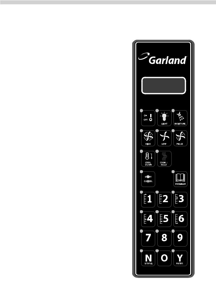
EXPLANATION OF CONTROLS, (Deluxe Models)
Programmable Control, (Deluxe Models)
Display
Five distinct areas of the LED display screen are common to most programming modes and cooking modes:
1. Upper left corner: displays the programmed temperature followed by the word SET..
2. Lower left corner: displays actual temperature currently monitored by the control, (cavity or probe), followed by the letters ACT..
3.Upper right corner: displays time in hours, minutes and seconds; (00:00:00)..
4.Lower right corner: displays the word HEAT to indicate when the burners or the elements are on and heating..
5.Lower center section: displays the operating mode.. While the oven is idling, this area is blank.. During a cooking cycle it will display COOK.. During a hold cycle it will display
HOLD..
Refer to the section entitled DISPLAY MESSAGES on page 23 for additional information regarding display messages and related button sequenced..
On/Off
Pressing this key once switches power modes, (ON or OFF)..
Light
Pressing the light key will activate the oven interior light for a period of 30 seconds..
The light can be programmed to turn on for 30 seconds when the door is opened when the oven is in Cool Down or to come on when the control is counting down..
Moisture
This key is used to manually activate the moisture function.. It is strongly recommended that moisture only be injected manually by holding the button for one second at a time..
During a cook cycle that is programmed for moisture, the LED will light while moisture is injected into the oven cavity..
Moisture can not be manually injected if the fan is running in
Pulse mode..
NOTE: Water can only be injected after the oven has preheated to at least 225°F (107°C)..
Page 18 |
Part # MPSM07 (03/24/08) |
High Fan
Pressing this key once will change the fan mode to high speed.. The LED will light as a visual indicator that the fan is operating at high speed..
Low Fan
Pressing this key once will change the fan mode to low speed.. The LED will light as a visual indicator that the fan is operating at low speed..
Pulse Fan
Pressing this key once will change the fan mode to pulse.. The LED will light as a visual indicator that the fan is operating in pulse mode..
In Pulse mode, the fan operates at low speed and is turned on and off at 30 second intervals after the programmed temperature is reached..
Note: during pulse mode, the fan will be on continuously during initial start-up.. After the oven has reached the programmed temperature, the fan will begin to pulse on and off.. While the fan is pulsing, the heat will only be active while the fan is on.. If the temperature probe calls for heat while the fan is off, the control will not activate the heat output until the fan turns on.. Moisture can not be injected manually during operation in Pulse Mode..
Cool Down
At any time the oven temperature is above 150°F, the oven can be cooled by pressing this button.. The heat will turn off, the fan will switch to high speed and the display will change to indicate that the oven is in Cool Down mode..
When the oven is shut off for the day by pressing the On/Off key, if the cavity temperature is above 200°F, Cool Down will automatically start.. The fan will run at the high speed setting.. The display will indicate “Auto Cool Down..”This cools the oven to 150°F to help extend the motor life..
Cook/Hold
Pressing this key activates the Hold feature.. At the end of the cooking cycle, the oven will continue to idle at the
programmed HOLD temperature, holding the oven’s contents at the desired temperature until serving..
Start/Cancel
Pressing this key begins or ends a cook cycle.. When in the idle mode, pressing the key once will activate the timer to the last programmed time period.. The display timer will count down the time remaining..
At the end of the cook cycle, an audible alarm will sound.. Pressing this key once will cancel the alarm..
To cancel a cooking cycle in progress, press and hold the key for three seconds.. The timer will stop and the oven will return to idle mode..
Program
Pressing this key enters the Program Mode.. In Program Mode, various key/display combinations allow the user to program oven control functions and to input/assign time, temperature and moisture parameters to recipe keys..
1.Press and hold the Program key for 3 seconds.. The display will indicate ENTER CODE.. Here, a pass code must be entered.. This security feature prevents unauthorized persons from changing recipe parameters..
2.Use the number key to enter 4 – 2 – 7 – 5.. Then press the Y/Enter key..
3.Press the N/Scroll key to select a recipe or system programming..
Numeric Keys
Use these keys to enter numeric values when programming the oven functions and/or recipe keys..
“N”/Scroll
During programming, the user will be required to answer yes or no to a question asked.. This key is used to input a “no” answer.. On other occasions, this key will be used to scroll through a list of choices..
“Y”/Enter
During programming, the user will be required to answer yes or no to a question asked.. This key is used to input a “yes” answer.. On other occasions, this key will be used to enter a selection from a list of choices..
Part # MPSM07 (03/24/08) |
Page 19 |
OPERATING INSTRUCTIONS, (Deluxe Models)
Programmable Control (Deluxe Models)
The design of the moisture+ and its controls allow the use of various operational feature sets alone or in combination: traditional (manual), or cook & hold, with or without a core probe, with or without moisture..
Refer to the section entitled DISPLAY MESSAGES on page 23 for additional information regarding display messages and related button sequences..
Start-Up
When beginning daily operation, the oven will typically be in the Off Mode.. The display will be blank..
Press the On/Off key once to turn the oven on.. The oven will automatically begin to operate.. When started, the oven will begin heating to the most recently programmed temperature, (factory default is 300°F).. The ready range is +10°F/-5°F..
The fan will operate at the most recently programmed speed (factory default is Low speed)..
The display will indicate LOW TEMP until the actual oven temperature is within the ready range.. When the oven has reached the programmed temperature, the display will indicate READY..
At the end of the day, press the On/Off key once to turn the oven off.. The word OFF is displayed for 30 seconds.. After 30 seconds the display will go blank.. The oven is in the Off Mode..
If the oven is turned off while the internal temperature is above 200°F, the Auto Cool Down function will begin, (refer to the following section for details).. After the cavity temperature has cooled to 150°F, the fan will stop and the display will indicate OFF as described in the previous paragraph.. This function protects the motor from being left in a heated state, which could shorten its useful life..
Auto Cool Down And Cool Down
When the On/Off key is placed in the OFF position while the oven’s internal temperature is at or above 200°F, the control will automatically enter Cool Down Mode.. With the doors closed, or partially open, the heat will shut off and the fan will run at high speed until the internal temperature drops to 150°F.. The display will indicate AUTO COOL DOWN.. When the temperature is decreased to 150°F, the control enters Off Mode..
Cool Down Mode may be manually activated at any time by pressing the Cool Down key once.. This deactivates heating.. The fan will run at high speed and the display will indicate COOLDOWN..
Cool Down Mode will engage when the door is closed, but it is recommended that Cool Down Mode is operated with the door slightly open as indicated on the display.. If the door is not open enough, the display will indicate
OPEN THE DOOR SLIGHTLY.. If the door is open too far the display will indicate CLOSE THE DOOR SLIGHTLY..
Start/Cancel
Press this key to begin or end a cook cycle.. When in Idle Mode, press the key once to activate the timer to the most recently programmed time period, (factory default is 30 minutes).. The timer will display a countdown of the time remaining..
A cook cycle will not be allowed to start if the oven has not reached the ready band, (+10°F/-5°F), of the programmed temperature..
Note: Ensure that ready band option is on, refer to system programming options..
To cancel a cooking cycle already in progress, press and hold the Start/Cancel key for three seconds.. The timer will stop and the oven will return to Idle Mode..
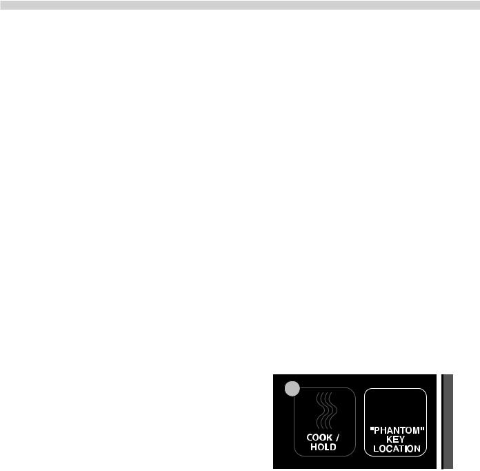
Changing the Temperature Scale, (°F or °C)
The control is capable of displaying temperatures in either Fahrenheit or Celsius, (factory default is Fahrenheit)..
A “phantom” key which functions as a toggle for the two temperature scales is located to the right of the Cook/Hold key as shown..
To change the scale, press and hold the phantom key for 3 seconds.. The current scale, (‘F’ or ‘C’), will be displayed, then changed.. This can be done at any time while power to the oven is turned on..
Basic Cook Cycle
NOTE: Before proceeding ensure that the manaul bake option is on, refer to system program options..
1.Press the On/Off key once..
2.Press the Program key once.. The display will indicate PROGRAM COOK TEMP.. Use the numeric keys to enter the desired cook temperature..
Page 20 |
Part # MPSM07 (03/24/08) |
Enter a number between 150 and 500, (factory default is 300).. If a number outside this range is entered, the control will sound an error tone and reset to the closest allowable number within the range..
3..Press the Program key a second time.. This stores and implements the temperature setting.. The display will indicate PROGRAM COOK TIME.. Use the numeric keys to enter the desired cooking time in hours, minutes and seconds..
Each time a key is pressed, the numbers displayed move one position left.. It may be necessary to enter zeros first to attain the desired result, for instance, to enter a time of 30 minutes, press, 0 - 0, (hours), 3 - 0, (minutes), 0 - 0, (seconds), resulting in a timer display of “00:30:00..”
4..Press the Program key a third time.. This stores and implements the time setting.. The display will indicate PROGRAM MOISTURE..
Press the N/Scroll key repeatedly to step through the available moisture setting choices until the desired setting is displayed.. Moisture setting presets for Meat, Bread, Poultry, Fish and None are included, along with a User setting to allow for custom moisture settings.. See “User Moisture Settings,” on page 26 for more information..
5..Press the Program key a fourth time.. This stores and implements the moisture setting.. This also exits programming mode..
6..Allow the oven to heat to the set temperature.. When the programmed temperature has been reached, the display will indicate READY..
7..Load the oven, close the door, and press the Start/Cancel key once to begin the cooking cycle/timer countdown..
Note: When the door is opened for loading, the internal temperature is likely to drop below the ready range. This is expected. The control allows 3 minutes for a user to load the product, close the door and press the Start/Cancel key to engage the timer. During this time, the control will ignore the drop in temperature. If the door is left open longer than 3 minutes, the cook cycle and timer countdown will not begin until the oven returns to the set temperature ready range and the display again indicates READY. If this happens, unload the oven, close the door, wait for the oven to return to READY, then repeat steps 6 and 7.
8..When time has expired, the display will indicate DONE and an audible alarm will sound continuously for 10 seconds.. Press the Start/Cancel key to cancel the alarm and unload finished product from the oven immediately.. The fan and heat will continue in idle mode..
If the alarm is not canceled after sounding continuously for 10 seconds, it will sound a short tone once every 15 seconds until the Start/Cancel key is pressed..
Using Cook & Hold
1.. Press the Cook/Hold key once to activate the cook & hold function.. The Cook/Hold key LED will light.. Pressing the key a second time will toggle the function off..
2.Press the Program key once.. The display will indicate PROGRAM COOK TEMP.. Use the numeric keys to enter the desired cook temperature..
Enter a number between 150 and 500, (factory default is 300).. If a number outside this range is entered, the control will sound an error tone and reset to the closest allowable number within the range..
3..Press the Program key a second time.. This stores and implements the temperature setting.. The display will indicate PROGRAM COOK TIME.. Use the numeric keys to enter the desired cooking time in hours, minutes and seconds..
Each time a key is pressed, the numbers displayed move one position left.. It may be necessary to enter zeros first to attain the desired result, for instance, to enter a time of 30 minutes, press, 0 - 0, (hours), 3 - 0, (minutes), 0 - 0, (seconds), resulting in a timer display of “00:30:00..”
4..Press the Program key a third time.. This stores and implements the Time setting.. The display will indicate PROGRAM MOISTURE..
Press the N/Scroll key repeatedly to step through the available moisture setting choices until the desired setting is displayed.. Moisture setting presets for Meat, Bread, Poultry, Fish and None are included, along with a User setting to allow for custom moisture settings.. See “User Moisture Settings,” on page 26 for more information..
5..Press the Program key a fourth time.. This stores and implements the moisture setting.. The display will indicate PROGRAM HOLD TEMP.. Use the numeric keys to enter the desired Hold temperature..
Enter a number between 140 and 210, (factory default is 160).. If a number outside this range is entered, the control will sound an error tone and reset to the closest allowable number within the range.. If a new Hold temperature
is not entered, the control will use the most recently programmed Hold temperature..
6..Press the Program key a fifth time.. This stores and implements the Hold temperature.. This also exits programming mode..
7..Allow the oven to heat to the programmed temperature.. When the programmed temperature has been reached, the display will indicate READY..
8..Load the oven, close the door, and press the Start/Cancel key once to begin the cooking cycle/timer countdown..
Part # MPSM07 (03/24/08) |
Page 21 |
Note: When the door is opened for loading, the internal temperature is likely to drop below the ready range. This is expected. The control allows 3 minutes for a user to load the product, close the door and press the Start/Cancel key to engage the timer. During this time, the control will ignore the drop in temperature. If the door is left open longer than 3 minutes, the cook cycle and timer countdown will not begin until the oven returns to the set temperature ready range and the display again indicates READY. If this happens, unload the oven, close the door, wait for the oven to return to READY, then repeat steps 7 and 8.
9..When time has expired the display will indicate DONE and an audible alarm will sound continuously for 3 seconds..
The fan will engage at low speed and the timer display will begin counting up from 00:00:00, indicating the amount of time the product has been held.. The Cook/Hold key LED will flash..
The oven will continue to idle at the programmed HOLD temperature until the function is canceled.. If there was a moisture setting active during the Cook cycle, moisture will remain active during the Hold cycle.. Press the Start/ Cancel key once to cancel the Hold and clear the timer..
Unload the finished-then-held product from the oven immediately.. The fan and heat will continue in Idle Mode, (at the programmed COOK temperature)..
Cooking With a Core Probe
1..Press the Cook/Hold key once to activate the cook & hold function.. The Cook/Hold key LED will light..
2..Press the Program key once.. The display will indicate PROGRAM COOK TEMP.. Use the numeric keys to enter the desired cook temperature..
Enter a number between 150 and 500, (factory default is 300).. If a number outside this range is entered, the control will sound an error tone and reset to the closest allowable number within the range..
3..Press the Program key a second time.. This stores and implements the temperature setting.. The display will indicate PROGRAM COOK TIME.. When cooking with a core probe, the COOK TIME setting is ignored.. The controller will override the time setting and monitor the probe temperature..
4..Press the Program key a third time.. The display will indicate PROGRAM MOISTURE..
Press the N/Scroll key repeatedly to step through the available moisture setting choices until the desired setting is displayed.. Moisture setting presets for Meat, Bread, Poultry, Fish and None are included, along with a User setting to allow for custom settings..
5..Press the Program key a fourth time.. This stores and implements the moisture setting.. The display will indicate PROGRAM HOLD TEMP.. Use the numeric keys to enter the desired Hold temperature..
Page 22
Enter a number between 140 and 300, (factory default is 160).. If a number outside this range is entered, the control will sound an error tone and reset to the closest allowable number within the range.. If a new Hold temperature
is not entered, the control will use the most recently programmed Hold temperature..
6..Press the Program key a fifth time.. This stores and implements the Hold temperature.. This also exits programming mode..
7..Allow the oven to heat to the set temperature.. When the programmed temperature has been reached, the display will indicate READY..
8..Insert the core probe into the food product to be monitored.. Load the oven, close the door, keeping the plug-end of the probe cable outside the oven..
Note: When the door is opened for loading, the internal temperature is likely to drop below the ready range. This is expected. The control allows 3 minutes for a user to load the product, close the door and press the Start/Cancel key to engage the timer. During this time, the control will ignore the drop in temperature. If the door is left open longer than 3 minutes, the cook cycle and timer countdown will not begin until the oven returns to the set temperature ready range and the display again indicates READY. If this happens, unload the oven, close the door, wait for the oven to return to READY, then repeat steps 7 and 8.
9..Plug the probe cable into the connector on the underside of the top cover above the control panel.. The display will indicate PROGRAM PROB TEMP.. Use the numeric keys to enter the desired internal product temperature at which the probe will signal that the product is done..
Enter a number between 120 and 300, (factory default is 150).. If a number outside this range is entered, the control will sound an error tone and reset to the closest allowable number within the range..
10.Press the Program key.. This stores and implements the probe temperature setting.. This also exits programming mode and begins the cooking cycle.. During the cooking cycle, the display will flash at two second intervals, alternately showing the programmed cook temperature and the programmed probe temperature..
11.When the probe senses that the programmed internal product temperature has been reached, the display will indicate DONE and an audible alarm will sound continuously for 3 seconds..
The fan will engage at low speed and the timer display will begin counting up from 00:00:00, indicating the amount of time the product has been held.. The Cook/Hold key LED will flash..
The oven will continue to idle at the programmed HOLD temperature until the function is canceled.. Press the Start/ Cancel key once to cancel the Hold and clear the timer.. Unload the finished-then-held product from the oven immediately.. The fan and heat will continue in Idle Mode, (at the programmed COOK temperature)..
Part # MPSM07 (03/24/08)
Programming Recipe Keys
For “one touch” cooking, each of the numeric keys, (1 through 9), on the keypad can be programmed to contain a product recipe consisting of 1 to 6 “profiles..” Each profile consists of
a set of cooking parameters which control that profile’s fan speed, cook temperature, cook time and moisture settings..
To program a recipe key:
1.Press and hold the Program key for 3 seconds.. The display will indicate ENTER CODE.. Here, a pass code must be entered.. This security feature prevents unauthorized persons from changing recipe parameters..
2.Use the numeric keys to enter 4 - 2 - 7 - 5.. Then press the Y/Enter key..
3. Press the N/Scroll key to select recipe or system programming..
4.The display will indicate PRESS KEY TO PROGRAM.. Choose the desired numeric key to which the new recipe will be assigned, and press that key..
Press the Y/Enter key.. The display will indicate PROGRAM SHELF.. Press the N/Scroll key..
5.The display will indicate PROGRAM FAN PROF1 SPEED..
Press the N/Scroll key repeatedly to step through the available fan speed choices, (HIGH, LOW, PULSE), until the desired speed for Profile 1 is displayed..
6.Press the Y/Enter key.. The fan setting will be stored and the display will indicate PROGRAM PROF1 COOK TEMP.. Use the numeric keys to enter the desired cook temperature..
Enter a number between 150 and 500, (factory default is 350).. If a number outside this range is entered, the control will sound an error tone and reset to the closest allowable number within the range..
7.Press the Y/Enter key.. This stores and implements the Profile 1 temperature setting.. The display will indicate PROGRAM PROF1 COOK TIME.. Use the numeric keys to enter the desired cooking time in hours, minutes and seconds..
Each time a key is pressed, the numbers displayed move one position left.. It may be necessary to enter zeros first to attain the desired result, for instance, to enter a time of 30 minutes, press, 0 - 0, (hours), 3 - 0, (minutes), 0 - 0, (seconds), resulting in a timer display of “00:30:00..”
8.Press the Y/Enter key.. This stores and implements the Profile 1 Cook time setting.. The display will indicate PROGRAM PROF1 MOISTURE..
Press the N/Scroll key repeatedly to step through the available moisture setting choices until the desired setting is displayed.. Moisture setting presets for Meat, Bread, Poultry, Fish and None are included, along with a User setting to allow for custom moisture settings.. See “User Moisture Settings,” on page 26 for more information..
9.Press the Y/Enter key.. This stores and implements the Profile 1 moisture setting.. The display will indicate CONTINUE Y/N..
10.To continue on to Profile 2 of the recipe, press the Y/Enter key and enter cooking parameters for Profile 2 as done for profile 1 in steps 4 through 9.. Up to 6 full profiles may be entered in this way for a single recipe..
To end cook cycle programming of a recipe after any of profiles 1 through 6 has been entered, choose NO at the CONTINUE prompt by pressing the N/Scroll key..
11.The display will indicate PROGRAM HOLD Y/N.. Press the Y/Enter key if a Hold cycle is desired for the recipe, or N/Scroll if a Hold cycle is not desired..
12.If NO was chosen in step 10, skip directly to step 12..
If YES was chosen in step 11, the display will indicate PROGRAM HOLD TEMP.. Use the numeric keys to enter the desired Hold temperature..
Enter a number between 140 and 210, (factory default is 160).. If a number outside this range is entered, the control will sound an error tone and reset to the closest allowable number within the range.. If a new Hold temperature
is not entered, the control will use the most recently programmed Hold temperature..
Press the Y/Enter key.. This stores and implements the Hold temperature setting..
13..The display will indicate CONTINUE Y/N.. To end recipe key programming, press the N/Scroll key..
To program another recipe key, press the Y/Enter key and repeat the procedure, beginning with step 3..
System Program Options
To change the system setting, follow steps 1 & 2 above, use the
N/Scroll key to select system programing and press Y/Enter to begin..
Program options are:
Manual Bake |
ON/OFF |
Light Mode |
ON/OFF |
Ready Band |
ON/OFF |
Flexible or Straight Time Select
Part # MPSM07 (03/24/08) |
Page 23 |
Cooking With a Recipe Key
1..If the oven is in Off Mode, press the On/Off key once..
2..Press the numeric key that has been assigned to the desired recipe.. This will begin the heating cycle..
3..Allow the oven to heat to the set temperature programmed in Profile 1 of the recipe.. When the programmed temperature has been reached, the display will indicate READY..
4..Load the oven and close the door.. Press the numeric key that has been assigned to the desired recipe.. That key’s LED will light.. Press the Start/Cancel key to begin the cook cycle..
Note: When the door is opened for loading, the internal temperature is likely to drop below the ready range. This is expected. The control allows 3 minutes for a user to load the product, close the door and press the recipe key to engage the timer. During this time, the control will ignore the drop in temperature. If the door is left open longer than 3 minutes, the cook cycle and timer countdown will not begin until the oven returns to the set temperature ready range and the display again indicates READY. If this happens, unload the oven, close the door, wait for the oven to return to READY, then repeat steps 3 and 4.
The display will indicate PROF1 and the timer will display a countdown of the total time left in the recipe..
When the time programmed for Profile 1 of the recipe has expired, the display will indicate PROF2, (if a second profile was programmed for the active recipe), and the timer will continue to display a countdown of the time left in of the recipe.. (The fan speed, cook temperature and moisture settings programmed for Profile 2 will also take effect..) The control will continue executing the profiles programmed for the active recipe in succession unless the recipe is cancelled by the user.. To cancel a recipe during cooking, press and hold the Start/Cancel key for three (3) seconds..
5..If a Hold cycle was programmed, when the time programmed for the final profile of the active recipe has expired, the display will indicate DONE and an audible alarm will sound continuously for 3 seconds..
The fan will engage at low speed and the timer display will begin counting up from 00:00:00, indicating the amount of time the product has been held.. The Cook/Hold key LED will flash..
The oven will continue to idle at the programmed HOLD temperature until the function is canceled.. Press the Start/ Cancel key once to cancel the Hold and clear the timer.. Unload the finished-then-held product from the oven immediately.. The fan and heat will continue in Idle Mode..
If a Hold cycle was not programmed, when the time programmed for the final profile of the active recipe has expired, the display will indicate DONE and an audible alarm will sound continuously for 10 seconds.. Press the Start/Cancel key to cancel the alarm and unload finished
Page 24
product from the oven immediately.. The fan and heat will continue in Idle Mode..
If the alarm is not canceled after sounding continuously for 10 seconds, it will sound a short tone once every 15 seconds until the active recipe key is pressed..
Using the Shelf Timer Feature
It may be beneficial to cook different items in the oven at the same time on different oven racks, (shelves) and load at different intervals.. Though the product must have the same temperature and fan speed, each shelf can be timed separately..
To program shelf timers:
1.Press and hold the Program key for 3 seconds.. The display will indicate ENTER CODE.. Here, a pass code must be entered.. This security feature prevents unauthorized persons from changing recipe parameters..
2.Use the numeric keys to enter 4 - 2 - 7 - 5.. Then press the Y/Enter key..
3. Press the N/Scroll key to select recipe or system programming..
4..The display will indicate PRESS KEY TO PROGRAM.. Choose the desired numeric key to which the shelf timer will be assigned, and press that key..
Press the Y/Enter key.. The display will indicate PROGRAM SHELF Y/N.. Press the Y/Enter key..
5..The display will indicate PROGRAM PROF1 FAN SPEED..
Press the N/Scroll key repeatedly to step through the available fan speed choices, (HIGH, LOW, PULSE), until the desired fan speed setting of all the products to be loaded is displayed..
6..Press the Y/Enter key.. This stores and implements the fan speed setting.. The display will indicate PROGRAM PROF1 COOK TEMP.. Use the numeric keys to enter the desired cook temperature for all the products to be loaded..
Enter a number between 150 and 500, (factory default is 350).. If a number outside this range is entered, the control will sound an error tone and reset to the closest allowable number within the range..
7..Press the Y/Enter key.. This stores and implements the temperature setting.. The display will indicate PROGRAM PROF1 COOK TIME.. Use the numeric keys to enter the desired cooking time in hours, minutes and seconds for the shelf to be timed..
Each time a key is pressed, the numbers displayed move one position left.. It may be necessary to enter zeros first to attain the desired result, for instance, to enter a time of 30 minutes, press, 0 - 0, (hours), 3 - 0, (minutes), 0 - 0, (seconds), resulting in a timer display of “00:30:00..”
8..Press the Y/Enter key.. This stores and implements the time setting.. The display will indicate PRESS KEY TO PROGRAM.. Choose the desired numeric key to which the next shelf timer will be assigned, and press that key..
Part # MPSM07 (03/24/08)
 Loading...