


INSTALLATION AND OPERATION MANUAL
"THE MASTER"
GAS CONVECTION OVEN
FOR YOUR SAFETY:
DO NOT STORE OR USE GASOLINE OR OTHER FLAMMABLE VAPORS OR LIQUIDS IN THE VICINITY OF
THIS OR ANY OTHER
APPLIANCE
WARNING:
IMPROPER INSTALLATION, ADJUSTMENT, ALTERATION, SERVICE OR MAINTENANCE CAN CAUSE PROPERTY DAMAGE, INJURY, OR DEATH. READ THE INSTALLATION, OPERATING AND MAINTENANCE INSTRUCTIONS THOROUGHLY
BEFORE INSTALLING OR
SERVICING THIS EQUIPMENT
PLEASE READ ALL SECTIONS OF THIS MANUAL AND RETAIN FOR FUTURE REFERENCE.
THIS PRODUCT HAS BEEN CERTIFIED AS COMMERCIAL COOKING EQUIPMENT AND MUST BE INSTALLED BY PROFESSIONAL PERSONNEL AS SPECIFIED.
IN THE COMMONWEALTH OF MASSACHUSETTS THIS PRODUCT MUST BE INSTALLED BY A LICENSED PLUMBER OR GAS FITTER. APPROVAL NUMBER: G-1-07-05-28
For Your Safety:
Post in a prominent location, instructions to be followed in the event the user smells gas. This information shall be obtained by consulting your local gas supplier.
Users are cautioned that maintenance and repairs must be performed by a Garland authorized service agent
using genuine Garland replacement parts. Garland will have no obligation with respect to any product that has been improperly installed, adjusted, operated or not maintained in accordance with national and local codes or installation instructions provided with the product, or any product that has its serial number defaced, obliterated or removed,
or which has been modified or repaired using unauthorized parts or by unauthorized service agents.
For a list of authorized service agents, please refer to the Garland web site at http://www.garland-group.com. The information contained herein, (including design and parts specifications), may be superseded and is subject to change without notice.
GARLAND COMMERCIAL INDUSTRIES, LLC |
GARLAND COMMERCIAL RANGES, LTD. |
U |
185 East South Street |
1177 Kamato Road, Mississauga, Ontario L4W 1X4 |
Swallowfie |
Freeland, Pennsylvania 18224 |
CANADA |
Telephone: |
Phone: (570) 636-1000 |
Phone: 905-624-0260 |
Fax: 081-84 |
Fax: (570) 636-3903 |
Fax: 905-624-5669 |
|
Part # 1955200 Rev 5 (03/19/10) |
© 2005 Garland Commercial Industries, LLC |
IMPORTANT INFORMATION
WARNING:
This product contains chemicals known to the state of California to cause cancer and/or birth defects or other reproductive harm. Installation and servicing of this product could expose you to airborne particles of glass wool/ceramic fibers. Inhalation of airborne particles of glass wool/ceramic fibers is known to the state of California to cause cancer. Operation of this product could expose you to carbon monoxide if not adjusted properly. Inhalation of carbon monoxide is known to the state of California to cause birth defects or other reproductive harm.
Keep appliance area free and clear of combustibles.
Page 2 |
Part # 1955200 Rev.5 (03/19/10) |

CONTENTS
IMPORTANT INFORMATION. . . . . . . . . . . . . 2 DIMENSIONS & SPECIFICATIONS . . . . . . . . 4 INTRODUCTION. . . . . . . . . . . . . . . . . . . . . . . . 5 INSTALLATION . . . . . . . . . . . . . . . . . . . . . . . . . 5
Installation Notes:. . . . . . . . . . . . . . . . . . . . . . . . . . . . 5
Installation Of Ovens Equipped With Casters . . 5
Installation Of Double Deck Models. . . . . . . . . . . 6
Gas Connection. . . . . . . . . . . . . . . . . . . . . . . . . . . . . . 7
Electrical Connection . . . . . . . . . . . . . . . . . . . . . . . . 7
Ventilation & Air Supply . . . . . . . . . . . . . . . . . . . . . . 7
Testing & Lighting Instructions . . . . . . . . . . . . . . . 8
OPERATION. . . . . . . . . . . . . . . . . . . . . . . . . . . . 9
Master 200 Solid State Control With
Electromechanical Timer . . . . . . . . . . . . . . . . . . . . . 9
In Of f Mode . . . . . . . . . . . . . . . . . . . . . . . . . . . . . . 9
Start Up. . . . . . . . . . . . . . . . . . . . . . . . . . . . . . . . . . 9
Fan Speed . . . . . . . . . . . . . . . . . . . . . . . . . . . . . . . 9
Lights. . . . . . . . . . . . . . . . . . . . . . . . . . . . . . . . . . . . 9
Cool Down. . . . . . . . . . . . . . . . . . . . . . . . . . . . . . . 9
Temperature . . . . . . . . . . . . . . . . . . . . . . . . . . . . . 9
Timer: . . . . . . . . . . . . . . . . . . . . . . . . . . . . . . . . . . 10
Master 450 Electronic Control With Cook-N-Hold And Master 455 Electronic Control With Cook-N-Hold & Core Probe . . . . . 10
In Of f Mode . . . . . . . . . . . . . . . . . . . . . . . . . . . . . 10
On Start Up . . . . . . . . . . . . . . . . . . . . . . . . . . . . . 10
Controller Keys . . . . . . . . . . . . . . . . . . . . . . . . . . 10
Fahrenheit/Celsius. . . . . . . . . . . . . . . . . . . . . . . 11
Operating the Controls . . . . . . . . . . . . . . . . . . 11
Cook-N-Hold Operation . . . . . . . . . . . . . . . . . 12
Core Probe Operation . . . . . . . . . . . . . . . . . . . 12
Setting Setback Feature . . . . . . . . . . . . . . . . . 12
Master 475 Electronic Programmable Control 12
Manual cooking . . . . . . . . . . . . . . . . . . . . . . . . . 12
Manual cooking using Cook-N-Hold. . . . . . 12
Programming Product Keys (Master 475) . 13
Cooking using the product keys
(Master 475) . . . . . . . . . . . . . . . . . . . . . . . . . . . . . 14 Verifying hold time (Master 475). . . . . . . . . . 14
Cooking with the Shelf Timer
(Master 475) . . . . . . . . . . . . . . . . . . . . . . . . . . . . . 14
PERFORMANCE RECOMMENDATIONS . . 15 COOKING GUIDE . . . . . . . . . . . . . . . . . . . . . . 16 COOK AND HOLD . . . . . . . . . . . . . . . . . . . . . 17 PROBLEMS / SOLUTIONS . . . . . . . . . . . . . . 18 CLEANING & MAINTENANCE . . . . . . . . . . . 19
Break-In Period . . . . . . . . . . . . . . . . . . . . . . . . . . 19
Exterior Cleaning . . . . . . . . . . . . . . . . . . . . . . . . 19
Interior Cleaning . . . . . . . . . . . . . . . . . . . . . . . . 19
Fan Area Maintenance . . . . . . . . . . . . . . . . . . . 19
MOTOR CARE . . . . . . . . . . . . . . . . . . . . . . . . .20
Part # 1955200 Rev.5 03/19/10) |
Page 3 |
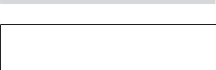
DIMENSIONS & SPECIFICATIONS
|
Single-Deck |
Int. Dimensions :In (mm) |
Ext. Dimensions: In (mm) |
Ship Wt |
|
Ship Dim. |
|
||||
|
Models |
W |
H |
D |
W |
H * |
D |
Lbs/kg |
|
Cubic Ft. |
|
|
Standard Depth |
29 (736) |
24 (610) |
24 (610) |
38 (965) |
57-1/2 (1461) |
41-1/4(1048) |
515/230 |
64 |
|
|
|
Deep Depth |
29 (736) |
24 (610) |
28 (711) |
38 (965) |
57-1/2 (1461) |
44-1/2(1130) |
545/245 |
64 |
|
|
|
|
|
|
|
|
|
|
|
|
|
|
|
|
|
|
|
|
|
|
|
|
|
|
|
Double-Deck |
Int. Dimensions: In (mm) |
Ext. Dimensions: In (mm) |
Ship Wt. |
|
Ship Dim. |
|
||||
|
Models |
W |
H |
D |
W |
H * |
D |
2@Lbs/kg |
|
Cubic Ft. |
|
|
|
|
|
|
|
|
|
|
|
|
|
|
Standard Depth |
29 (736) |
24 (610) |
24 (610) |
38 (965) |
70-1/2 (1791) |
41-1/4(1048) |
1030/465 |
|
128 |
|
|
Deep Depth |
29 (736) |
24 (610) |
28 (711) |
38 (965) |
70-1/2 (1791) |
44-1/2(1130) |
1090/490 |
|
128 |
|
|
|
|
|
|
|
|
|
|
|
|
|
*Height with or without standard casters. Height with low profile casters (double deck) is 68-1/2" (1740mm).
Models |
|
Input Ratings, Nat & Pro |
Electrical Specifications |
|
||||
BTU/hr |
|
kW Equiv. |
Gas Inlet |
120V/1Ph. |
240V/1Ph. |
|
||
|
|
|
||||||
|
|
|
|
|
|
|
|
|
Single Deck |
60,000 |
|
17. 6 |
(1 )@ 3/4" NPT |
(1)@9.8A |
(1)@ 5.2A |
|
|
|
|
|
|
|
|
|
|
|
Double Deck |
120,000 |
|
35.2 |
(1 )@1" NPT |
(2)@9.8A |
(2)@ 5.2A |
|
|
|
|
|
|
|
|
|
|
|
3/4" N.PT. |
|
|
1-1/4" |
|
|
1" REAR |
||
GAS INLET |
|
|
|
|
GAS INLET |
|||
|
|
|
|
|||||
|
|
|
|
[32mm] |
|
|
|
|
|
|
|
|
|
|
|
|
|
7-3/4" |
2" |
|
|
|
[197mm] |
[51mm] |
|
|
|
|
|
32-1/8" |
|
32-1/8" |
3/4" |
|
[816mm] |
|
|
|
|
|
[816mm] |
|
[19mm] |
|
|
|
|
|
|
|
|
|
FLUE: 2-3/8"x5" |
|
|
|
|
[60mmx127mm] |
|
|
|
|
D |
38-1/4" |
H |
|
|
(includes |
[972mm] |
|
32-1/8" |
|
fan motor) |
|
|
|
|
|
|
|
[816mm] |
|
|
|
|
|
|
|
|
32-1/8" |
|
|
|
|
[816mm] |
|
35-7/16” |
|
|
|
|
|
|
11-1/2" |
|
|
[900mm] |
|
|
|
|
|
17-3/4" |
[292mm] |
|
|
14-3/4" |
[451mm] |
|
|
|
|
|
6-1/4" |
DOUBLE DECK |
[375mm] |
|
|
|
|||
TOPVIEW |
|
[159mm] |
FR ONTVIEW |
|
|
|
|
|
|
|
|
38" |
|
|
|
|
|
|
|
|
||||
|
|
|
|
|
|
|
|
|
|
|
|
|
|
||||||
1-1/4" |
|
|
|
|
|
|
|
|
[965mm |
] |
|
|
|
|
3/4" REAR |
||||
|
|
|
|
|
|
|
|
|
|
|
|
|
|
|
|
|
|
GAS INLET |
|
[32mm] |
|
|
|
|
|
|
|
|
|
|
|
|
|
|
|
|
|
||
|
|
|
|
|
|
|
|
|
|
|
|
|
|
|
|
|
|
|
|
|
|
|
|
|
|
|
|
|
|
|
|
|
|
|
|
|
|
|
|
|
|
|
|
|
|
|
|
|
|
|
|
|
|
|
|
|
|
|
|
|
|
|
|
|
|
|
|
|
|
|
|
|
|
|
|
|
|
|
|
32-1/8" [816mm]
H 54-9/16"
[1386mm]
34"
25-3/8" [864mm] [645mm]
SINGLE DECK
FR ONTVIEW
Installation Notes:
Combustable Wall Clearances:
Sides: 1" (25mm)
Back: 3" (76mm)
Entry Clearance:
Crated: 47" (1194mm)
Uncrated: 32-1/2" (826mm)
Operating Pressure:
Natural: 4.5" WC (11 mbar) Propane: 10" WC (25 mbar) Max 13.8" WC @ 70°F (21°C)
NOTE: Data applies only to North America
Notes:
1.Standard electrical specifications include motor requirements.
2.(120V units) 115V 3/4 HP, 2-speed motor; 1140 and 1725 rpm 60Hz
3.(240V units) 200-240V, 3/4 HP, 2-speed motor; 1140 and 1725 rpm, 60Hz
4.A 6 ft. line cord is provided for each 120V deck with a (NEMA #5-15P) plug.
5.Garland recommends a separate 15 AMP circuit for each 120V unit.
Gas Input ratings shown here are for installations up to 2,000-ft. (610m) above sea level. Specify altitudes over 2,000 ft. Commercial cooking equipment requires an adequate ventilation system. For additional information, refer to the National Fire Protection Association’s standard NFPA96, “Vapor Removal from Cooking Equipment.” (NOTE: For North America only)
Please specify gas type when ordering.
Page 4 |
Part # 1955200 Rev.5 (03/19/10) |

INTRODUCTION
CONGRATULATIONS! You have just purchased the finest commercial cooking equipment available anywhere.
Like any other fine, precision built appliance, it should be given regular care and maintenance. Periodic inspections by your dealer or a qualified service agency is recommended. When corresponding with the factory or your local authorized
factory service center regarding service problems or replacement parts, be sure to refer to the particular unit by the correct model number (including the prefix and suffix letters and numbers) and the warranty serial number. The rating plate located behind the lower front panel (below the oven doors) contains this information.
INSTALLATION
Installation Notes:
Combustible and Non-Combustible Wall Clearance: Side: 1.0" (25 mm)
Rear: 3.0" (76 mm).
NOTE: Adequate clearance must be provided for servicing and proper operation.
The importance of the proper installation of Commercial Gas Cooking Equipment cannot be over stressed. Proper performance of the equipment is dependent, in great part, on the compliance of the installation with the manufacturer's specifications. Installation must conform to local codes or, in the absence of local codes, with the National Fuel Code, ANSI
Z223.1, Natural Gas Installation Code, CAN/CGA-B149.1, or the Propane Installation Code, CAN/CGA-B149.2, as applicable.
Before assembly and connection, check gas supply.
A.The type of gas for which the unit is equipped is stamped on the data plate located behind lower front panel. Connect a unit stamped "NAT" only to natural gas; connect a unit stamped "PRO" only to propane.
B.If it is a new installation, have gas authorities check meter size and piping to assure that the unit is supplied with sufficient amount of gas pressure required to operate the unit.
C.If it is additional or replacement equipment, have gas authorities check pressure to make certain that existing meter and piping will supply fuel at the unit with not more that 1/2" water column pressure drop.
NOTE: When checking pressure be sure that all other equipment on the same gas line is on. An internal pressure regulator is supplied with GARLAND Convection Ovens. Regulator is preset to deliver gas at pressure shown on the rating plate.
Part # 1955200 Rev.5 03/19/10)
The appliance and its individual shut-off valve must be disconnected from the gas supply piping system during any pressure testing of that system at test pressures in excess of 1/2 PSI (3.45 kPa).
The appliance must be isolated from the gas supply piping system by closing its individual manual shut-off valve during any pressure testing of the gas supply piping system at test pressures equal to or less than 1/2 PSI (3.45 kPa).
Installation Of Ovens Equipped With Casters
A.For an appliance equipped with casters, the installation shall be made with a connector that complies with the Standard for Connectors for Movable Gas Appliances, ANSI Z21.69 /CSA 6.16, and a quick-disconnect device that complies with the Standard for Quick-Disconnect Devices for Use With Gas Fuel, ANSI Z21.41 / CSA 6.9, and adequate means must be provided to limit the movement of the appliance without depending on the connector and the quick-disconnect device or its associated piping to limit the appliance movement and the location(s) where the restraining means may be attached to the appliance shall be specified.
B.The front casters of the unit are equipped with brakes to limit the movement of the oven without depending on the connector and any quick-disconnect device or its associated piping to limit the appliance movement.
C.The restraint can be attached to the unit near the gas inlet. If the restraint is disconnected, be sure to reconnect the restraint after the oven has been returned to its originally installed position.
Page 5
INSTALLATION Continued
Installation Of Double Deck Models
A.Position insert in bottom leg opening and tap insert up into leg till it seats at collar. Attach six inch (6") legs to lower oven section. Raise unit or lay on its left side. Place the front legs on the oven so as to line up with four (4) attaching bolt holes. Secure leg to oven frame using (4) 3/8-16 x 3/4 bolts and washers provided. Repeat at rear of unit.
B.Remove lower front cover of top deck (located under oven doors). Raise top deck into place and line up body sides and back of the unit. Fasten the rear of the units together, with the stacking bracket, using (6) 1/4-20 machine screws, lock washers and nuts, (provided).
C.Install the interconnecting flue parts, carefully following the instructions contained in the stacking kit. Pay particular attention to the type of ovens you are stacking and be sure to follow the corresponding instructions.
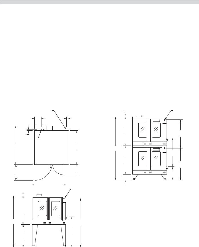
D.Assemble the stacking pipes provided in the stacking kit as shown in the diagram at the top of this page. This allows both ovens to be supplied by a single gas line. The minimum recommended size of a single supply line for
two stacked ovens is 1 inch. Use a pipe thread compound that is intended for use on propane gas piping and be sure to check for leaks before finalizing the installation.
E.Check leveling of unit four (4) ways (using a common carpenter's level on the rack inside the oven).
F.Plug the cord set of each unit into a 115-Volt power supply outlet.
G.Maintain clearance from combustibles.
Each gas appliance shall be located with respect to building construction and other equipment so as to permit access to the appliance. Such access and clearance may be necessary for servicing and cleaning.

 90 Degrees Street Elbow
 20 1/2" Nipple
3/4" to 1" Bell Reducer
 3" Nipple
3/4" Union |
3" Nipple |
 90 Degrees Street Elbow
CAUTION:
DISCONNECT BOTH UNITS FROM ELECTRICAL SUPPLY BEFORE SERVICING.
POWER FAILURE
In the event of a power failure, no attempt should be made to operate this oven.
IMPORTANT
All gas burners and pilots need sufficient air to operate and large objects should not be placed in front of this oven, which would obstruct the airflow through the front. Objects should not be placed on main top rear of oven while in use. This could obstruct the venting system of the unit's flue products.
Page 6 |
Part # 1955200 Rev.5 (03/19/10) |
INSTALLATION Continued
Gas Connection
The 1" NPT inlet at the rear must be considered in piping the gas supply for double stack units or ¾" NPT for individual (or single deck) connections. Undersized gas supply line(s) may restrict the gas supply and affect performance. If other gas appliances are supplied by the same supply line, the supply line must be sized to carry the combined volume without causing more than 1/2" pressure drop at the manifold of each appliance on the line at full rate.
Recommended supply pressures are 7" WC, (NAT), and 11" WC, (PRO); ± 5%. (Must not exceed 13.8" WC [NAT], and 15" WC [PRO]).
Electrical Connection
A 15 AMP service must be provided for each oven. For 115 VAC usage, a cord and plug (NEMA #5-15P) is provided but connection to the electrical service must be electrically grounded in accordance with local codes, or in the absence of local codes, with the National Electrical Code, ANSI/NFPA 70, or the Canadian Electrical Code, CSA C22.2, as applicable.
This appliance is equipped with a three-prong (grounding) plug for your protection against shock hazard and should be plugged directly into a properly grounded three-prong receptacle.
DO NOT CUT OR REMOVE THE
GROUNDING PRONG FROM THIS PLUG.
A wire diagram is affixed to the rear of the unit.
Ventilation & Air Supply
Proper ventilation is highly important for good operation. There are only two choices for properly venting an oven: 1) canopy hood style or 2) direct venting. The ideal method of venting a GAS Convection Oven is through the use of a
properly designed canopy, which should extend 6" (150 mm), beyond all sides of the appliance and 6'6" (1950 mm) from the floor.
A strong exhaust fan will create a vacuum in the room. For an exhaust system vent to work properly, exhaust and make-up air must be balanced properly. For proper air balance contact your local H.V.A.C. contractor.
All gas burners and pilots need sufficient air to operate and large objects should not be placed in front of this oven, which would obstruct the airflow through the front. Installation Of A Direct Flue
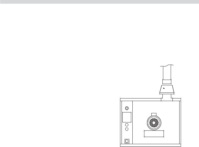
When the installation of a canopy type exhaust hood is impossible the oven may be direct vented. Before direct venting check your local codes on ventilation, in the absence of local codes, refer to the National Fuel Code NFPA 54, ANSI Z223.1 (latest revision).
If the unit is to be connected directly to a direct flue, it is necessary that draft diverter be installed to insure proper ventilation.
DRAFT DIVERTER 

Direct venting, should be positioned on the main top and fastened with sheet metal screws provided.
NOTE: Each oven has been factory tested and adjusted prior to shipment. It may be necessary to further adjust the oven as part of a proper installation. Such adjustments are the responsibility of the installer. Adjustments are not considered defects in material and workmanship, and they are not covered under the original equipment warranty.
DO NOT UNDER SIZE VENT PIPE!
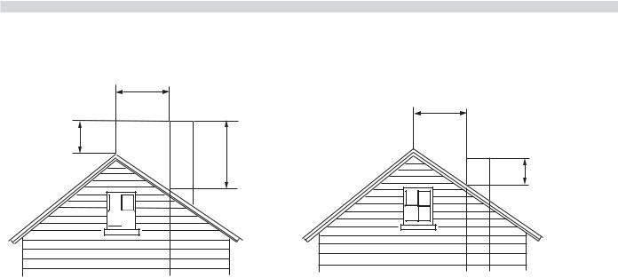
This can cause resistance to flow and impede good venting. We suggest that if a horizontal run must be used it should rise no less than 1/4" (6.25mm) for each linear foot of run, and after a total of 180° of bends you should increase the size of stove pipe by two (2") inches. The flue should rise 2' (60cm) to 3' (90cm) above the roofline or 2' (60cm) to 3' (90cm) above any portion of a building within a horizontal distance of 10 (3 meters) feet.
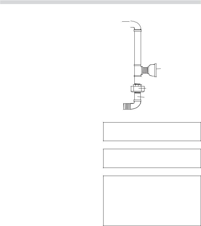
The following diagram is only one example from the National Fuel Gas Code Book NFPA 54, ANSI Z223.1, 7.5.3:
Part # 1955200 Rev.5 03/19/10) |
Page 7 |
INSTALLATION continued
Less than 10 feet (3 meters)
More than 10' (3 meters)
2' (60cm)
Min.
3' (90cm) Min.
3' (90cm) Min.
Termination Less than 10 feet (3 meters) from ridge
Testing & Lighting Instructions
1.Turn on main gas valve. Remove the lower front cover and the service panel above the control panel. Drop the control panel and leak test all fittings and connections upstream from the service valve located on the redundant combination gas valve. Should any gas leaks be detected, turn OFF main gas valve, correct the problem and retest.
2.Open shutoff valve located on the redundant combination gas valve. Activate control panel and set to desired temperature. The pilot burner is ignited by direct spark, main burners are then ignited by the pilot. Check all fittings again and correct any leaks and recheck.
Replace all service panels and covers before operation.
NOTE: All electronic ignition systems are supplied with a redundant gas valve. Therefore, the unit is not supplied with an external pressure regulator.
Termination More than 10 feet (3 meters) from ridge
NOTE: During installation there will be air in the gas line. This air will have to bleed off before ignition can be established. The electronic ignition system has a ninety second lock-out as a safety device on all units. Therefore, several attempts may be required before pilot ignition is established, wait five minutes after each attempt.
FOR YOUR SAFETY: KEEP YOUR APPLIANCE AREA FREE FROM
COMBUSTIBLES.
TO CONSERVE ENERGY:
Do not waste energy by leaving controls at high temperature settings during idle periods. Lower settings will keep
oven warm and ready for next use period. Master 400 Series controls have an auto setback feature that is user programmable to help with these applications.
Page 8 |
Part # 1955200 Rev.5 (03/19/10) |

OPERATION
Master 200 Solid State Control With
Electromechanical Timer
In Off Mode
When the oven is off, there are no lights or indicators.
Start Up
Press the Cook/Off/Cool Down rocker switch to the “Cook” position. The green lamp will light indicating the oven is powered in cook mode.
The oven will begin to heat to the temperature set on the thermostat dial. The amber lamp will light indicating the heat is active. As the heat cycles on and off to maintain the set temperature this light will go on and off accordingly.
The door must be closed for the oven to operate in cook mode. Opening the door will cause the heat to stop. The motor and fan will shut off. This is a safety feature.
Fan Speed
The fan speed can be either high (1725RPM) or (1150 RPM). The fan speed is controlled by the left rocker switch marked high and low.
Lights
The oven lights are activated by pressing the light switch on the control panel. This is a momentary switch and the lights will stay lit as long as this button is held in the on position.
Lights will work whenever there is electrical power connected to the oven.
Cool Down
Pressing the Cook/Off/Cool Down rocker switch to the Cool Down position activates the fan and motor to cool the oven cavity. The door must be open slightly for the fan and motor to start. The heat is not active in this mode.
Optimal cool down will be achieved with the door open slightly. Opening the door too far will shut the fan and motor off. This is a patented safety feature.
Pressing the button to the OFF position cancels the cool down and turns the oven off.
Temperature
The temperature range is from 150°F to 500°F (66°C to 250°C) is controlled by rotating the temperature dial and aligning the indicator to the desired temperature.
Part # 1955200 Rev.5 03/19/10) |
Page 9 |
OPERATION Continued
Timer
The timer is set by rotating the dial clockwise aligning the indicator to the desired time cycle. The timer will count down from 2 minutes to 60 minutes. At the end of the timing cycle the buzzer will sound. The buzzer is turned off by rotating the dial counter-clockwise to the off position as shown on the control panel.
NOTE: The timer does not control heating.
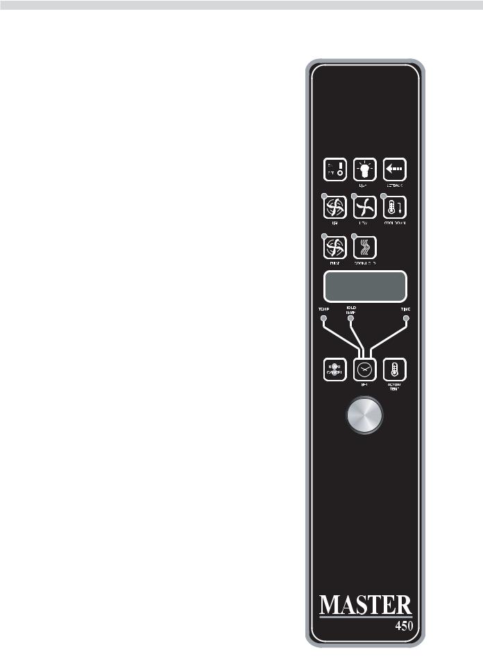
Master 450 Electronic Control With Cook-N-Hold And Master 455 Electronic Control With Cook-N-Hold & Core Probe
In Off Mode
When the controller is off, the display will show "OFF". Pressing the ON/OFF key will activate the controller into Start Up mode.
On Start Up
In Start Up mode, the controller will heat to the last set temperature, time and fan speed. The factory defaults are 350°F (177°C), 30 minutes and low fan speed. The display will indicate "LO" when the oven is below the set temperature. When the oven cavity reaches the set temperature and is ready for operation the display will indicate "LOAD".
NOTE: If the oven temperature goes above the requested temperature the display will indicate "HI". If the oven temperature goes above 575°F (302°C) the display will indicate "HELP" and an audible signal will sound. This is a safety feature.
If the door is opened during a Cooking mode, the fan and heat will stop, and the display will indicate "DOOR" until the door is closed. This is a patented safety feature.
Pressing the ACTUAL TEMP key will display the actual oven temperature in 5° increments.
Controller Keys
Pressing the ON/OFF key will activate the oven.
Pressing the LIGHT key will turn the lights on for 30 seconds. The lights will work if the controller is in the Off mode. When the door is opened, the light will come on and stay on for 30 seconds.
Pressing the FAN HIGH key will activate the higher fan speed and light its LED.
Pressing the FAN LOW key will activate the lower fan speed and light its LED.
Page 10 |
Part # 1955200 Rev.5 (03/19/10) |
OPERATION continued
Pressing the FAN PULSE key will activate the lower fan speed and light its LED. The fan will be active for 30 seconds then off for 30 seconds, and continues this cycle.
Pressing the SETBACK key will cool the oven cavity to a preprogrammed temperature, see: Setting "Set-Back" Feature. The oven will automatically go into Setback mode after the pre-programmed non-usage time. The display will indicate "SETB". This is an energy-saving feature.
Pressing the COOL DOWN key will deactivate the heat, turn the fan on high and light its LED. The display will indicate "OPEN DOOR" if the door is closed, prompting the user to open the door slightly. With the door open slightly the display will indicate "COOL". The Cool Down will operate when the door is closed or opened slightly. Optimal cool-down will be achieved with the door open slightly. When the door opens wider, the Cool Down mode will deactivate and the display will indicate "DOOR". This is a patented safety feature. Pressing the COOL DOWN key again will turn the LED off and stop this mode. Pressing the ON/OFF key will also cancel Cool Down. Cool Down is not active during a cook.
When the ON/OFF switch is pressed to turn the oven off and the oven was above 200°F (93°C), the oven will go into an Auto Cool Down mode. In Auto Cool Down, the oven will run the fan on high until the oven cavity drops below 150°F (66°C). During this time the display will indicate "AUTO". When the oven temperature drops below 150°F (66°C) the oven turns off. This feature protects the oven motor from premature failure. Optimal cool-down will be achieved with the door open slightly.
Fahrenheit/Celsius
Factory default is Fahrenheit (F). To change to
Celsius (C), press and hold in the "Phantom Key" located to the right of "Cook/Hold" key. "F" appears in the display. Continue to hold until "C" is displayed and then release the "Phantom key".
Operating the Controls
Setting the cook temperature and time are done in the same manner. Pressing the SET key will light the TEMP LED. The operator then sets the temperature by rotating the dial on the controller until the desired temperature is shown on the display. Pressing the SET key a second time lights the TIME LED and allows the operator to select the desired cook time as shown on the display. Pressing the SET key a third time ends the programming.
Part # 1955200 Rev.5 03/19/10) |
Page 11 |

OPERATION Continued
Pressing the START/CANCEL key will start the timing cycle. The display will count down from the Set time in minutes and seconds (solid colon) or hours and minutes (blinking
colon) the minutes and seconds. When the cycle is completed, pressing this key will also cancel the "DONE”prompt. To cancel a timing cycle in progress, press and hold the START/CANCEL key for 3 seconds.
Cook-N-Hold Operation
Pressing the COOK/HOLD (450 and 455 Controllers Only) key activates the Cook-N-Hold mode and lights its LED. To verify the proper hold temperature has been selected, press the SET key twice. The display will show the hold temperature. At the end of the cook cycle, an audible alarm will sound, the display will flash “DONE” and change to count "UP" the hold time. The oven will switch to the programmed hold temperature.
Setting the cook temperature, hold temperature and time are done in the same manner. Pressing the SET key will light the TEMP LED. The operator then sets the temperature by rotating the dial on the controller until the desired temperature is shown on the display. Pressing the SET key a second time
will light the HOLD LED and allows the operator to select the desired hold temperature as shown on the display. Pressing the SET key a third time lights the TIME LED and allows the operator to select the desired cook time as shown on the display. Pressing the SET key a fourth time ends the programming.
Pressing the START/CANCEL key will start the timing cycle. When the cycle is completed, pressing this key will also cancel the "DONE" prompt. To cancel a timing cycle in progress press and hold the START/CANCEL key for 3 seconds.
Core Probe Operation
The Core Probe option (455 Controller Only) is only active when the core probe is plugged into its connector. To set the core temperature, first plug the core probe into its connector. The display will indicate "100" and the CORE TEMP LED will be on. The operator then sets the temperature by rotating the dial on the controller until the desired temperature is shown on the display. Pressing the SET key stores the core temperature and starts the cooking process.
To set the oven temperature, press the SET key again. The TEMP LED will light and the oven temperature can be set by rotating the dial on the controller until the desired temperature is displayed. Pressing the SET key again will light the HOLD LED allowing the operator to set the hold temperature in the same manner.
NOTE: If the hold temperature is not set, the default hold temperature is 150°F (66°C) or the last programmed temperature. (Hold temperature range is 140°F (60°C) to 210°F (99°C).
Page 12
When the core temperature is reached, the display will sound and flash "DONE" for 3 seconds. Automatically, the display will switch to count "UP” the time the oven is on hold.
Setting Setback Feature
To set or change the setback settings, press and hold the SETBACK key for two seconds. The TEMP LED will light and a temperature will be displayed. Set the temperature using the dial, then press the SET key. The TEMP LED will go out and the TIME LED will light ("Time" is factory set at 0). Set the time using the dial, then press the SET key. Press the SET key one more time to exit programming.
Note: To disable the setback function, set the temperature to 250º F (121ºC) and the time to zero.
Master 475 Electronic Programmable Control
Manual cooking
1.Press SET key - TEMP LED will light.
2.Set temperature using the dial (factory preset at 350°F).
3.Press SET key - FAN LED will light.
4.Select fan mode using one of the three (3) fan keys (HIGH, LOW, PULSE) - the selected fan LED will light
5.Press SET key - TIME LED will light
6.Set cook time using the dial (factory preset at 30:00).
7.Press SET key - ready to cook.
8.Press START/CANCEL to begin manual cooking.
Manual cooking using Cook-N-Hold
1.Press the COOK/HOLD key, that key's LED will light.
2.Press SET key - TEMP LED will light.
3.Set cook temperature using the dial (factory preset at 350°F)
4.Press SET key - HOLD LED will light.
5Set hold temperature using the dial (factory preset at 200°F).
6.Press SET key - FAN LED will light.
7.Select fan mode using one of the three (3) fan keys ( HIGH, LOW, PULSE ) - the selected fan LED will light.
8.Press SET key - TIME LED will light.
9.Set cook time using the dial (factory preset at 30:00).
Part # 1955200 Rev.5 (03/19/10)

OPERATION Continued
10.Press SET key - ready to cook
11.Press START/CANCEL to begin manual cooking
Programming Product Keys (Master 475)
NOTE: Cooking time(s) is the element of the program that tells the controller that other information (temperature, fan speed, etc.) will be inputted into the controller. The first step is to enter all the time periods required, followed by the addition of the other cooking elements.
1.Press and hold PROG key for three (3) seconds - all the product key LEDs light.
2.CODE will be displayed. The controller is asking for the access code. Press 4-2-7-5 and the START/CANCEL key.
PROD will be displayed indicating you have gained access to Product Programming.
3.Press the product key (1 - 9) into which you want to store a cooking program. SHLF will be displayed. The control is asking if you want to program the key as a shelf timer or with a cooking profile. Select your answer by pressing the START/CANCEL key. When the correct answer is displayed, press the SET key. The TIME LED will light. 30:00 will be displayed.
4.Set first cook time using dial. If more than one cooking profile is desired:
•press the product key where the program is to be stored (1 - 9) - PR-2 will be displayed.
•set the second cook time using the dial (factory presets for PR-2 through PR-5 are :00).
•press the same product key (1 - 9) again - PR-3 will be displayed.
•Repeat this process for all profiles. When the last profile time has been entered, press the SET key, OR
If less than five (5) profiles are desired press the SET key after the last required profile - PRE will be displayed, followed by :00. The controller is asking if you would like a reminder alarm (pre-alarm) to sound during the cooking process. (factory preset is :00)
5.If a pre-alarm signal is desired - dial in the time that the alarm is to sound. (Ex. If the product is to be turned halfway through the 60 minute cooking cycle, set the
pre-alarm to 30 minutes). If pre-alarm is not desired verify that ":00" is displayed. Press the SET key - TEMP Led will light, and the display will show the first profile cooking temperature. (factory preset at 350°F)
6.Set the first cooking temperature using the dial.
Part # 1955200 Rev.5 03/19/10) |
Page 13 |

OPERATION Continued
Press the product key - PR-2 will be displayed followed by the second temperature.
Set the second cooking time using the dial.
Repeat as you did for cooking time, for all the profiles desired.
NOTE: The controller will only accept cooking temperatures for the number of profiles for which a cooking time has been set. If the product key is pressed after the last programmed profile, the first temperature will be displayed.
Press SET after the last cooking temperatures has been entered, HOLD will be displayed.
7.Use the START/CANCEL key to select yes or no. Press the SET key.
8.If yes was selected, the HOLD LED will light. Enter the hold temperature using the dial. (factory preset at 200°F) Press the SET key. FAN will be displayed and the FAN LED will light.
•Set the fan speed desired for the first cooking profile using the individual fan keys (HIGH, LOW or PULSE), press the product key and set the fan speed for the second cooking profile. Continue until all the profiles have been assigned a fan speed. Press the SET key when complete. As with the temperature, if the product key is pressed after the last programmed profile, the first fan speed will be displayed.
9.FL or St will be displayed (for flex time or straight time) (factory preset for flex time). Select flex or straight time using the START/CANCEL key for the first profile. Press the product key and select straight time or flex time for the second profile. Continue until all the profiles have been assigned straight or flex time. Press the SET key when complete. If the product key is pressed after the last programmed profile, the first profile will be displayed.
10.Programming for that product key is complete.
Cooking using the product keys (Master 475)
1.On initial start-up, press the product key for the menu item to be cooked. Wait until LOAD is displayed.
2.Load the oven.
3.Press the product key for the loaded menu item.
4.Press the START/CANCEL key.
5.To cancel the alarm or the hold, press the START/CANCEL key followed by the product key.
Verifying hold time (Master 475):
While a product is being held, press and hold the product key. The actual hold time will be displayed.
Selecting Fahrenheit or Celsius (Master 475):
Press PROG and ACTUAL TEMP keys at the same time, F or C will be displayed. (factory preset for F)
Press the START/CANCEL key to switch between F and C.
When the desired setting is displayed press the PROG and ACTUAL TEMP keys at the same time.
Cooking with the Shelf Timer (Master 475)
The shelf timer option is used to independently time each of the up to six different shelves or racks within the oven.
NOTE: To use the shelf timer option, at least one product key must be programmed with a cooking profile (temperature, time, fan speed, flex or straight time). The program key must be limited to a single cooking profile to be used with the shelf timing option. If more than one product key is to be used,
all product keys to be used must feature the same cooking temperature and fan speed. Flex or straight time and cooking time can de different. The Cook-N-Hold option can not be used with the shelf timer operation.
Pressing the desired product key will bring the oven to the desired cooking temperature, once the oven has reached the proper cooking temperature as indicated by LOAD in the display,
1.Press the shelf key for the shelf location to be timed (1 - 6). NOTE: product keys and shelf keys are the same keys.
2.Press the START/CANCEL key to begin the cooking/timing process.
3.When the cooking/timing process is complete for each shelf, an audible "done" signal will sound and the display will indicate which shelf is finished. Example: SH-1
4.To turn off the alarm press the product key with the flashing LED.
Example: Two product profiles contain the same cooking temperature, fan speed and are both programmed for flex time - keys 1 and 6.
Page 14 |
Part # 1955200 Rev.5 (03/19/10) |
 Loading...