


Electric Dual Side Clamshell Broiler
Model: CXBE12-1
Service Manual
This manual is updated as new information and models are released. Visit our website for the latest manual.
Document Number: G_EB_SM_CFABROILER (11/14)

Safety Notices
 DANGER
KEEP APPLIANCE AREA FREE AND CLEAR OF COMBUSTIBLES.
nWarning
Do not store or use gasoline or other flammable vapors or liquids in the vicinity of this or any other appliance.
nWarning
Improper installation, adjustment, alteration, service or maintenance can cause property damage damage, injury, or death. read the installation, operating and maintenance instructions thoroughly before installing or servicing this equipment..
nWarning
Accessible parts may become hot during use. Young children should be kept away. This appliance is not intended for use by persons (including children) with reduced physical, sensory or mental capabilities, or lack of experience
and knowledge, unless they have been given supervision or instruction concerning use of the appliance by a person responsible for their safety.
nWarning
This product contains chemicals known to the state of california to cause cancer and/or birth defects or other reproductive harm. Installation and servicing of this product could expose you to airborne particles of glass wool/ceramic fibers. Inhalation of airborne particles of glass wool/ ceramic fibers is known to the state of california to cause cancer. Operation of this product could expose you to carbon monoxide if not adjusted properly. Inhalation of carbon monoxide is known to the state of california to cause birth defects or other reproductive harm.
nWarning
The broiler grates will get extremely hot. Even close up it may not appear to be hot but can cause burn if touched.
,Caution
This equipment must be installed and commissioned by a professional, factory-trained technician.
,Caution
This equipment must be operated under an approved hood system in accordance with local regulations in force. This unit is intended for indoor use only.
,Caution
Use care when moving this unit. This unit cannot be dropped as it will impact the performance of the electronics
,Caution
Do not sit or stand on the appliance under any circumstances. Serious injury and damage to the appliance and/or property could result.
Notice
For Your Safety:
Post in a prominent location, instructions to be followed in the event the user smells gas. This information shall be obtained by consulting your local gas supplier.
Notice
This appliance is intended for commercial use only and should only be operated by fully trained and qualified personnel.
Notice
Scrape the grease trough and chute, directing any grease/debris into the grease drawer. Once cool enough to handle, empty grease drawer, scraping out stubborn grease/debris and wash drawer in a hot soapy solution.
Notice |
• Take care not to expose the power cord to heat (i.e. |
|
near the flue, etc.) and be careful not to damage the |
||
Do not operate the broiler unless it has been commis- |
||
cord by pinching or rubbing on sharp edges |
||
ioned (Start-Up) by a Factory Authorized Service Center. |
• This appliance is for professional use and shall be |
|
|
||
Do not operate the broiler without reading this opera- |
used only by qualified personnel. |
|
tion manual. |
• This product has been certified as commercial |
|
Do not operate the broiler unless it has been properly |
cooking equipment and must be installed by |
|
professional personnel as specified. |
||
installed and grounded. |
||
• Ensure that he unit does not contain food debris or |
||
Do not operate the broiler unless all service and access |
||
is obstructed in any way. A clean cooking surface is |
||
panels are in place and fastened properly. |
||
imperative for proper operation |
||
|
||
Do not use an extension cord to connect this appliance |
• Ensure electrical supply conforms with electrical |
|
to a power supply. |
characteristics shown on the rating plate. |
|
Do not use this appliance if the power cord is |
• Installation and electical connection must comply |
|
with current codes. |
||
damaged. Do not attempt to repair a damaged power |
||
In Canada - The Canadian Electrical Code Part 1 and |
||
cord. |
||
Local Codes. |
||
Do not clean the broiler with a power washer. This ap- |
||
In USA – The National Electrical Code ANSI / NFPA – |
||
pliance is not approved for power washing. |
||
Do not operate the appliance unless all panels and |
Current Edition. |
|
• The electrical power supply must be disconnected |
||
covers are installed. |
||
prior to cleaning or any maintenance or service work |
||
Do not allow overfill grease box, should be emptied as |
being done on the appliance. |
|
required. |
• The appliance generates significant amounts of heat |
|
Use only stainless steel, wood or plastic tools to scrape off |
and the operator should take care when touching |
|
accessible surfaces that are likely to get hot. Surfaces |
||
heavy deposits or oil. Do not use ordinary steel scrapers |
close to the cooking surface including side panels |
|
or knives, as iron particles may become embedded and |
may get hot enough to burn skin. |
|
rust. NEVER USE STEEL WOOL. |
• Do not cool off a hot broiler with ice. The use of |
|
|
ice may damage the castings, crack the welds, |
|
NOTE: |
or warp the broiler grate castings which will |
|
• Please read all sections of this manual and retain for |
void the warranty. |
|
• Once the unit has cooled, external stainless |
||
future reference. |
||
|
steel panels should be cleaned using a mild |
• This product is not authorized for home or |
|
|
Safety Notices (continued) |
||
residential use Garland will not provide service, |
detergent and/or a food-safe liquid cleaner |
|
designed to clean stainless steel. If necessary |
||
warranty, maintenance, or support of any kind |
||
to use a nonmetallic scouring pad, always rub |
||
other than in commercial applications. |
||
in the direction of the grain in the metal to |
||
• Do not attempt to service this appiance unless you |
||
prevent scratching. |
||
are a qualified service technician (as it will void your |
||
• It is recommended to clean the control screen |
||
warranty). |
||
only with a damp soft cloth. |
||
|
||
|
|
|
Shipping Damage Claim Procedure |
|
|
Please note that the Garland equipment was carefully inspected and packed by skilled personnel before leaving the factory. The transportation company assumes full responsibility for safe delivery upon acceptance of the equipment. What to do if the equipment arrives damaged:
1.File a claim immediately regardless of the extent of damage.
2.Be sure to note, “visible loss or damage,” on the freight bill or express receipt and have the person
making the delivery sign it.
3.Concealed loss or damage: if damage is unnoticed until the equipment is unpacked, notify the freight company immediately, (within 15 days), and file a concealed damage claim.

Table of Contents
Safety Notices..................................................................................................................... |
2 |
Shipping Damage Claim Procedure.................................................................................. |
3 |
Section 1
General Information
Dimension Specificationh ................................................................................................. |
6 |
Shipping Dimensions and Weight..................................................................................... |
7 |
Electrical Input Specifications........................................................................................... |
7 |
Introduction........................................................................................................................ |
8 |
Packing....................................................................................................................................................... |
8 |
Unpacking................................................................................................................................................. |
8 |
Temporary Storage ................................................................................................................................ |
8 |
Safety .......................................................................................................................................................... |
8 |
Section 2
Installation
Install Requirements.......................................................................................................... |
9 |
General....................................................................................................................................................... |
9 |
Rating Plate .............................................................................................................................................. |
9 |
Positioning and Setup .......................................................................................................................... |
9 |
Appliances Equipped with Casters .................................................................................................. |
9 |
Air Supply and Ventilation ............................................................................................................... |
10 |
Remove Clamshell Broiler from Wood Crate.................................................................. |
11 |
Front Caster Adjustment ................................................................................................. |
12 |
Remove stainless steel plastic film cover.................................................................................... |
13 |
Temperature Verification ................................................................................................ |
13 |
Thermocouple Locations Diagram ................................................................................. |
14 |
Thermocouple Locations Diagram ................................................................................. |
15 |
Section 3
Operation
easyToUCH™ Home & Recipes Selector Pages................................................................ |
16 |
START UP COOKING:......................................................................................................... |
19 |
Cooking a Recipe.............................................................................................................. |
20 |
Change to a Recipe Cook Cycle ....................................................................................... |
21 |
Sleep Mode ....................................................................................................................... |
21 |
Section 4
Maintenance
Daily, Cleaning (at the end of the day) ........................................................................... |
26 |
Section 5
Troubleshooting
Cooking Issues.................................................................................................................. |
31 |
Temperature Issues .......................................................................................................... |
33 |
UI issues ............................................................................................................................ |
35 |
4 |
Document Number: G_EB_SM_CFABROILER (11/14) |

Table of Contents (continued) |
|
Section 6 |
|
Controls |
|
Instructions for Software Update ................................................................................... |
43 |
SETTINGS MODE:.............................................................................................................. |
47 |
Change the date .................................................................................................................................. |
47 |
Change the time.................................................................................................................................. |
47 |
Change the language ........................................................................................................................ |
47 |
Change password................................................................................................................................ |
48 |
Change brightness.............................................................................................................................. |
48 |
Change volume.................................................................................................................................... |
48 |
Change time and gap ........................................................................................................................ |
48 |
Section 7 |
|
Component Check Procedures |
|
Reading the LEDs - SIB .................................................................................................... |
49 |
Reading the LEDs - SIB - Diagnose Platen Errors........................................................... |
50 |
Reading the LEDs - SIB - Platen Homing ........................................................................ |
51 |
Reading the LEDs - SSRB.................................................................................................. |
52 |
Latch System Internal Operation - A, Unlatching .......................................................... |
53 |
Latch System Internal Operation - B, Latching .............................................................. |
54 |
Lower Grate Adjustment Procedure ............................................................................... |
55 |
Gap Calibration & Upper Platen Assembly Levelling .................................................... |
57 |
Upper Platen Levelling .................................................................................................... |
58 |
Exhaust Motor Fuse Replacement .................................................................................. |
60 |
Exhaust Motor Assembly Replacement.......................................................................... |
61 |
Reinstall blower wheel to the motor .............................................................................. |
61 |
Lower Grate Replacement Procedure............................................................................. |
62 |
Lower Infrared Element Replacement Procedure.......................................................... |
63 |
Upper Grate Element Replacement Procedure.............................................................. |
64 |
To Remove The Exhaust Fan Assembly........................................................................... |
65 |
To Install the IR Tent ......................................................................................................... |
67 |
To Install the brush holder............................................................................................... |
68 |
To Install the tool holder.................................................................................................. |
68 |
Section 9 |
|
Diagrams |
|
Wiring Diagram ................................................................................................................ |
69 |
Section 10 |
|
Tools & Cleaning Supplies |
|
Grill Accesories ................................................................................................................. |
70 |
Document Number: G_EB_SM_CFABROILER (11/14) |
5 |

Section 1
General Information
Dimension Specificationh
 12.5 [318]
23.8 |
[606] |
37.8 |
[960] |
3.6 [91]
8.2 [207]
|
|
|
COOKING SURFACE |
|
|
|
|
|
49 |
[1245] |
|
|
|
|
|
31.6 |
[801] |
APPROXIMATE |
|
|
|
|
|
|
|
|
|
|
|
33.0 |
[839] |
|
|
|
|
|
|
|
|
|
|
|
6.0 |
[152] |
|
|
|
|
±0.5[12.7] |
FOR LEVEL |
|
|
|
|
|
|
|
ADJUSTMENT(FRONT CASTERS ONLY) |
|
|
|
|
|
|
12.7 |
[323] |
23.3 |
[591] |
7.8 |
[198] |
|
|
|
|
|
|
||||
|
10.2 |
[259] |
|
|
|
|
|
|
MODEL |
HEIGHT* |
WIDTH |
|
DEPTH |
|
|||
|
|
|
|
|
|
|
|
|
|
Inches |
mm |
Inches |
|
mm |
Inches |
|
mm |
CXBE12-1 |
49 |
1245 |
12.5 |
|
318 |
37.8 |
|
960 |
* Height shown to top of the flexible conduit and therefore indicated as approximate.
6 |
Document Number: G_EB_SM_CFABROILER (11/14) |

Section 1 |
General Information |
|
|
Shipping Dimensions and Weight
|
SHIPPING DIMENSIONS |
|
||
MODEL |
|
inches (mm) |
|
|
|
Length |
Width |
Height * |
|
|
43 1/2” |
27 3/8” |
49 5/8” |
Shipping Weight |
|
(1105mm) |
(695mm) |
(1260mm) |
545 lbs/247 Kg |
|
UNCRATED DIMENSIONS |
|
||
CXBE12-1 |
|
inches (mm) |
|
|
|
Length |
Width |
Height |
|
|
37 13/16” |
12 1/2” |
49” |
Unit Weight |
|
(960mm) |
(960mm) |
(1245mm) |
480 lbs/218 Kg |
* 44”(118mm) without exhaust fan
Electrical Input Specifications
|
|
|
ELECTRICAL REQUIREMENTS** |
|
|
|
||
|
|
|
|
|
Unbalance 3 phase |
|||
MODEL |
OPTIONS |
Voltage (V) |
Total kW |
Frequency |
|
|
Amps |
|
|
|
|
per line |
|
||||
|
|
|
|
(Hz) |
|
|
||
|
|
|
|
|
L1 |
|
L2 |
L3 |
CXBE12-1 |
with fan |
208 / 3phase |
16.05 |
60 |
43.4 |
|
43.4 |
47.0 |
without fan |
208 / 3phase |
16.00 |
60 |
43.2 |
|
43.2 |
47.0 |
|
|
|
|||||||
A 5-foot (1.5m) long power supply cord with an integral (NEMA 15-50) plug is provided with each model.
Note: Wiring diagram is supplied with each unit.
Document Number: G_EB_SM_CFABROILER (11/14)

General Information |
Section 1 |
|
|
Introduction
GARLAND RECOMMENDS THAT INSTALLATION, MAINTENANCE AND REPAIRS BE DONE BY AN AUTHORIZED SERVICE AGENCY, OTHERWISE THE WARRANTY WILL BE DEEMED NULL AND VOID. FOR A LIST OF AUTHORIZED SERVICE AGENTS, REFER TO THE GARLAND WEB SITE AT http://www.garland-group.com.
This appliance should be given regular care and maintenance to operate at peak performance and maximum energy efficiency. It is recommended that the unit be inspected every 6 months
by a certified service technician for proper operation and performance. Remember “regular maintenance ensures peak performance.”
Every broiler is inspected and tested at the factory prior to shipment.
PACKING
The product is shipped in a substantial crate with the broiler in vertical position. Casters are factory installed on the broiler. Garland places the unit/ accessories in the crate in a neat and organized manner and in such a way as to eliminate damage from movement, rubbing etc.
Check crate for any visible damage sustained during transit.
It is recommended to remove crate when the clamshell broiler is inside the kitchen.
UNPACKING
CAUTION
Heavy load
Use of lifting aids and proper lifting technique required
Carefully remove unit from crate and thoroughly inspect it for any visible or concealed damage. Report any damage immediately to your carrier to file the appropriate freight claims. For more information, see page 4. Push or pull broiler must be taken care to see that the broiler does not tip over.
Do not remove any permanently affixed labels, warnings or data plates from the appliance as this may invalidate the Garland warranty.
TEMPORARY STORAGE
Garland provides adequate protection under normal conditions. The broiler may need additional protection if it is stored near salt water, a tropical area, or other unfavorable conditions. You must contact Garland immediately if these conditions occur.
SAFETY
It is essential that the instructions in this manual be strictly followed for the safe and economical operation of the equipment. Should it be known or suspected that a fault exists with the appliance, then it must not be used until the fault is rectified by a authorized or certified service person.
This appliance provides a sleep mode which ensures the unit avoids overheating when idle.
8 |
Document Number: G_EB_SM_CFABROILER (11/14) |
Section 2
Installation
Install Requirements
THIS PRODUCT IS NOT AUTHORIZED FOR HOME OR RESIDENTIAL USE. GARLAND WILL NOT PROVIDE SERVICE, WARRANTY, MAINTENANCE, OR SUPPORT OF ANY KIND OTHER THAN IN COMMERCIAL APPLICATIONS.
GENERAL
In the United States the installation must comply with the latest edition of the National Electrical Code ANSI/NFPA 70 – latest edition and/or local Codes to assure safe and efficient operation.
POSITIONING AND SETUP
CAUTION
Heavy load
Use of lifting aids and proper lifting technique required
In other countries installation must be carried out by a factory authorized service representative according to the relevant regulations, codes of practice and the related requirements of the country of destination.
Adequate clearance must be provided for servicing and proper operation.
If you have any questions regarding the installation of this unit, contact the Manitowoc KitchenCare at (855)-586-1542 or Garland Regional Service Managers.
RATING PLATE
Two (2) rating plates will be installed on each unit, and they can be found:
a.Inside the front panel under the electronic touch control.
b.The lower edge of the right exterior body side near the front of the unit.
|
|
If service or replacement |
|
|
parts are needed, refer to |
|
|
the model number |
|
|
(including prefix & suffix |
|
|
letters/numbers) and serial |
|
|
number on the rating plate |
|
|
when in contact with the |
|
b |
factory or authorized service |
a |
agency. These numbers |
|
|
ensure proper unit |
|
|
|
identification, faster and more accurate service.
The unit is very heavy (500 Lbs) so some form of mechanical assistance is recommended to lift and position the broiler.
The unit is designed to be placed on a smooth and level floor built to withstand the weight of the fully laden appliance. To comply with NSF Sanitation Standards the unit must stand on casters for ease of mobility during cleaning procedures.
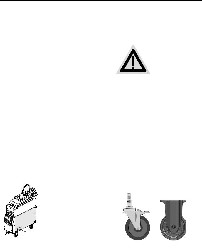
APPLIANCES EQUIPPED WITH CASTERS
All broilers are shipped with casters installed in place, however some adjustment may be required to level the unit. The front casters are adjustable swivel casters with brakes. The rear casters are fixed. Garland recommends installing restraining chains/cables from the floor/wall to the rear of the unit. These restraints limit the mobility of the appliance.
FRONT CASTER WITH BRAKE |
REAR CASTER WITHOUT BRAKE |
Document Number: GAR-SM-CXBE12-1 (11/14) |
9 |

Installation |
Section 2 |
|
|
AIR SUPPLY AND VENTILATION
VENTILATION REQUIREMENTS MAY BE SUBJECT TO LOCAL BUILDING AND FIRE CODES. CONSULT LOCAL AUTHORITIES HAVING JURISDICTION.
This broiler appliance must be vented properly to operate correctly and safely. Due to the extremely high temperature a fire safety system should be installed. In addition, frequent cleaning of the vent hood and the appliance greatly reduces any fire risk.
For any commercial cooking appliance, means must be provided to exhaust combustion waste products, steam, etc. to the outside of the building. Proper ventilation is essential for optimum performance.
Air movement should be checked during installation. There must be adequate air intake into the building to compensate for the amount of air removed by the ventilation system. Without a proper balance, abnormal atmospheric pressure will occur, affecting burner and appliance performance. If air movement is a concern, adjustments should be made to correct the problem by Factory authorized service technician.
HAVING DIFFICULTY OPENING DOORS THAT EXIT THE BUILDING IS AN INDICATION THAT THE
BUILDING HAS A PROBLEM WITH AIR MOVEMENT.
Do not use fans to blow air directly at the appliance. This can create air cross-currents and/or excessive drafts that interfere with the operation of the unit.
|
HIGH |
DISCONNECT THE POWER SUPPLY BEFORE SERVICING. |
VOLTAGE |
IMPORTANT: The appliance must be electrically grounded in accordance with local codes, or in the absence of local codes, with the National Electrical Code ANSI/NFPA70, or the Canadian Electrical Code CSA C22.2, as applicable.
Electrical Grounding Instructions
The appliance is equipped with a standard Nema 15-50 plug with appropriate strain relief for your protection against shock hazard and should be plugged directly into a properly grounded three prong receptacle. Do not cut or remove the grounding prong from this plug.
Important Electrical Precautions
Never touch anything that is powered by electricity when your hands are wet.
It is recommended to allow enough slack on the electrical cord to allow the appliance to be pulled out for proper regular cleaning and maintenance.
DO NOT USE AN EXTENSION CORD TO CONNECT THIS UNIT TO A POWER SUPPLY.
DO NOT USE THIS APPLIANCE IF THE POWER CORD IS DAMAGED.
DO NOT ATEMPT TO REPAIR A DAMAGED POWER CORD.
DO NOT EXPOSE THE POWER CORD TO HEAT OR SHARP EDGES.
DO NOT OPERATE BROILER IF THE CORD HAS BEEN PINCHED OR HAS BEEN DAMAGED AS A RESULT OF RUBBING ON SHARP EDGES.
10 |
Document Number: G_EB_SM_CFABROILER (11/14) |
Section 2 |
Installation |
Remove Clamshell Broiler from Wood Crate
CAUTION
Heavy load
Use of lifting aids and proper lifting technique required
The unit is very heavy (500Lbs) so some form of mechanical assistance may be required to lift and position the broiler.
Personal Protective Equipment (PPE) required.
STOP! - FOLLOW THE INSTRUCTIONS BELOW TO SAFELY AND EASILY REMOVE UNIT FROM PACKAGING SKID
Tools required.
1.REMOVE AND DISCARD FRONT STOP BOARD (ITEM “A”) NAILED TO FRONT OF SKID.
2.REMOVE AND DISCARD TWO (2) #10-24 X 2 1/2” LONG TRUSS HEAD PHILLIPS DRIVE MACHINE SCREWS AND FLAT WASHERS FROM THE LOWER SUPPORT BRACE (“ITEM B”) ON EACH SIDE OF UNIT.
3.REMOVE AND DISCARD TWO (2) # 10-24X1/2” HEX HEAD SCREWS (BROILER SIDE) FROM THE BACK LOWER SUPPORT ANGLE (“ITEM C”) ON BACK OF UNIT.
NOTE: ENSURE FRONT CASTER BRAKES ARE OFF.
4.PUSH UNIT FORWARD OFF OF THE SKID. THE LOWER SIDE SUPPORT BRACES WILL SERVE AS GUIDES AND ENSURE THAT THE UNIT ROLLS STRAIGHT AS IT IS BEING MOVED.
5.REPLACE THE FASTENERS REMOVED FROM EACH SIDE OF THE UNIT IN STEP 2 WITH TWO (2) #10-24 X ½” LONG PAN HEAD PHILLIPS DRIVE MACHINE SCREWS INCLUDED WITH UNIT ACCESSORIES.
WARNING
|
|
|
|
|
|
|
|
|
|
|
|
|
|
|
|
|
|
|
|
|
|
|
|
|
|
|
|
|
|
|
GENTLY PUSH THE BROILER |
||||
DO NOT MOVE THE BROILER |
||||||||
USING THE FRONT PANEL |
OUT OF THE CRATE. |
|||||||
GUARDS. |
|
|
|
|
|
|||
Document Number: G_EB_SM_CFABROILER (11/14)

Installation |
Section 2 |
|
|
Front Caster Adjustment
1. Turn the clamshell |
|
broiler Green Power Main |
ON |
Switch OFF. ( “0”position) |
|
|
OFF |
2. Rear Casters are fixed - DO NOT ATTEMPT TO ADJUST THEM.
3. Adjust the two (2) front casters only.
4. Lock the caster using the caster brake (Note: applying the caster brake system will lock the wheel and the swivel of the caster assembly).
5. Carefully raise front of unit slightly so that front wheels are off the ground and no longer bearing unit weight.
6.Loosen caster jam nut by turning it clockwise with a wrench.
7.Adjust the caster assembly by turning the caster (brake on) clockwise to increase the height or counterclockwise to decrease the height.
8.After the broiler is completely level, tighten caster jam nut to secure the caster assembly.
IMPORTANT NOTE
DO NOT TOUCH CASTER NUT
On the caster assembly shown above there is a nut used to assemble the swivel system - do not use wrench on this nut. This nut is intended for the caster swiveling system only.
12 |
Document Number: G_EB_SM_CFABROILER (11/14) |

Section 2 |
Installation |
|
|
IMPORTANT NOTE:
Prior to installation, check the electrical supply to ensure input voltage and phase match the equipment - voltage rating and phase. Many local codes exist and it is the responsibility of the owner/installer to comply with these codes.
Certified
Installer
Ensure power supply is connected to the appliance.
Remove all factory applied protective material by washing with hot water, mild detergent, or a soap solution.
NOTE: Each clamshell broiler has been factory tested and adjusted prior to shipment. It may be necessary to further adjust the unit as part of a proper installation. Such adjustments are the responsibility of the installer. Adjustments are not considered to be defects in material and workmanship and are not covered under the original equipment warranty.
REMOVE STAINLESS STEEL PLASTIC FILM COVER
Removing this film is one of the things that must be done once the broiler is in place. The film covers both internal and external components (e.g. Side panels, crumb tray, grease shield) and must be removed before turning the broiler on.
1.Using a plastic scraper wedge the film away from the stainless steel.
2.Grasp and pull the film very gently away from the stainless steel.
Temperature Verification
HOT SURFACE
Grill Temperatures
Will Cause Severe
Burns
The upper and lower clamshell broiler cooking surfaces must be cleaned.
The broiler is designed and rated for operating conditions where the temperature is above 32F.
1.The upper and lower clamshell broiler should be at operating temperatures to perform this calibration verification (approximately 30 minutes).
2.Place temperature probe over the thermocouple A as per figure #1 (under: thermocouple locations diagram). Allow about 10 seconds for the pyrometer to respond and stabilize temperature.
3.Temperature delta between pyrometer and controller must be +/- 200F. If temperature delta between pyrometer and controller is greater than +/- 200F, call Manitowoc KitchenCare at 1- 855-586-1542.
4.Repeat for thermocouples located at positions B, C, & D.
PEEL |
OFF |
PLASTIC |
FILM |
|
|||
|
|
||
|
|
|
Document Number: G_EB_SM_CFABROILER (11/14)
Installation |
Section 2 |
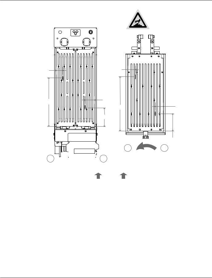
Thermocouple Locations Diagram
THERMOCOUPLE LOCATION
HOT SURFACE
Grill Temperatures
Will Cause Severe
Burns
2.72” |
2.35” |
|
|
A |
|
C |
|
|
|
||
14.92” |
2.72” |
2.35 |
|
|
|||
B |
14.73” |
||
|
|||
|
7.68” |
D |
|
|
|
||
|
|
7.23 |
|
|
R |
L |
|
|
|
|
|
|
|
|
|
|
|
|
|
|
|
|
L |
|
|
|
R |
COOKING AREA |
||
|
|
|
|||||
|
|
COOKING AREA |
|
||||
|
|
|
-TOP- |
||||
|
|
|
-BOTTOM- |
|
|||
|
|
|
|
|
|||
|
|
|
|
|
|
GRILL FRONT |
|
|
|
|
|
|
|
||
A = Bottom Left Rear |
|
C = Top Right Rear |
|||||
B = Bottom Right Front |
|
D = Top Left Front |
|||||
Figure #1
Startup Form Procedure
A factory startup is a comprehensive clamshell broiler check in which a factory certified technician will document all final settings programmed in the controller once various other performance checks are complete. The estimated time to complete a startup is approximately 1.5
– 2 hours. Please keep in mind this estimated time when scheduling the startup. After hours or overtime is not covered under warranty and will be billed at a charge which is the difference
between the Garland Reimbursement rate and the Factory Authorized Service Centers overtime charges. A factory startup is necessary to start the warranty period. The Authorized Service Center is required to complete the paperwork during the startup process, and send it to Garland Commercial Ranges for reimbursement. At the time of receipt, Garland will start the warranty as mentioned in the Warranty section.
14 |
Document Number: G_EB_SM_CFABROILER (11/14) |

Section 2 |
|
|
|
|
|
|
|
|
|
|
|
|
|
|
|
|
|
|
|
|
|
|
|
|
|
|
|
|
|
|
|
|
|
|
|
|
|
|
|
|
|
|
|
|
|
|
|
|
|
Installation |
|
|
|
|
|
|
|
|
|
|
|
|
|
|
|
|
|
|
|
|
|
|
|
|
|
|
|
|
|
|
|
|
|
|
|
|
|
|
|
|
|
|
|
|
|
|
|
|
|
|
|
|
|
Thermocouple Locations Diagram |
|
|
|
|
|
|
|
|
|
|
|
|
|
|
|
|
|
|
|
|
|
|
|
|
|
|
|
|
|
|
|
|
|
|
|
|
|
|
|
|
|
|
|
|
|
|
|||||
|
|
|
|
|
|
|
|
|
|
|
|
START UP CHECKLIST |
|
|
|
|
|
|
|
|
|
|
|
|
|
|
|||||||||||||||||||||||||
|
|
|
|
|
|
|
|
|
|
|
|
|
|
|
|
|
|
|
|
|
|
|
|
|
|
|
|
|
|
|
|
|
|
|
|
|
|
|
|
|
|
|
|
|
|
|
|
|
|
||
|
Serial #: |
|
|
|
|
|
|
|
|
|
|
|
|
|
|
|
|
|
|
|
|
|
|
Date: |
|
|
|
|
|
|
|
|
|
|
|
|
|
|
|||||||||||||
|
|
|
|
|
|
|
|
|
|
|
|
|
|
|
|
|
|
|
|
|
|
|
|
|
|
|
|
|
|
|
|
|
|
|
|
|
|
|
|
|
|
|
|
|
|
|
|
|
|
||
|
CFA Store #: |
|
|
|
|
|
|
|
|
|
|
|
|
|
|
|
|
|
|
|
|
|
|
Phone #: |
|
|
|
|
|
|
|
|
|
|
|
|
|
|
|||||||||||||
|
|
|
|
|
|
|
|
|
|
|
|
|
|
|
|
|
|
|
|
|
|
|
|
|
|
|
|
|
|
|
|
|
|
|
|
|
|
|
|
|
|
|
|
|
|
|
|
|
|
|
|
|
Address: |
|
|
|
|
|
|
|
|
|
|
|
|
|
|
|
|
|
|
|
|
|
|
|
|
|
|
|
|
|
|
|
|
|
|
|
|
|
|
|
|
|
|
|
|
|
|
|
|
||
|
|
|
|
|
|
|
|
|
|
|
|
|
|
|
|
|
|
|
|
|
|
|
|
|
|
|
|
|
|
|
|
|
|
|
|
|
|
|
|
|
|
|
|
|
|
|
|||||
|
City: |
|
|
|
|
|
|
|
State: |
|
|
|
|
|
|
|
|
|
|
|
|
|
|
|
|
Zip Code: |
|
|
|
|
|
||||||||||||||||||||
|
|
|
|
|
|
|
|
|
|
|
|
|
|
|
|
|
|
|
|
|
|
|
|
|
|
|
|
|
|
|
|
|
|
|
|
|
|
|
|
|
|
|
|
|
|
|
|
|
|
|
|
|
|
|
|
|
|
|
|
|
|
|
|
|
|
|
|
|
|
|
|
|
|
|
|
|
|
|
|
|
|
|
|
|
|
|
|
|
|
|
|
|
|
|
|
|
|
|
|
|
|
|
|
|
ELECTRIC / 3 PHASE |
INPUT SPECIFICATION: 208V |
|
MEASURE VOLTAGE FROM OUTLET: L1 L2 |
L2 L3 |
|
L3 L1 |
|
|
|
|||||||||||||||||||||||||||||||||||||||||
|
|
|
|
|
|
|
|
|
|
|
|
|
|
|
|
|
|
|
|
|
|
|
|
|
|
|
|
|
|
|
|
|
|
|
|
|
|
|
|
|
|
|
|
|
|
|
|
|
|
|
|
1 |
Confirm if the outlet in the store is NEMA15 50R by checking the box on the side. If the outlet is other than NEMA15 50R, DO NOT INSTALL the |
OK |
|||||||||||||||||||||||||||||||||||||||||||||||||
clamshell broiler until this issue is resolved. Call Garland Service at 1 855 586 1542. |
|
|
|
|
|
|
|
|
|
|
|
|
|
|
|
|
|
|
|||||||||||||||||||||||||||||||||
|
2 Remove unit from package. Inspect for any obvious shipping damage. Shipping material under the platen will be removed at a later step. |
|
|
|
|||||||||||||||||||||||||||||||||||||||||||||||
|
3 |
Remove side panel and ensure line cord is secured to the contactor. Check all wiring at the terminal block for tightness. Check all pin connectors |
|||||||||||||||||||||||||||||||||||||||||||||||||
to ensure they are secure. |
|
|
|
|
|
|
|
|
|
|
|
|
|
|
|
|
|
|
|
|
|
|
|
|
|
|
|
|
|
|
|
|
|
|
|
|
|
|
|
|
|
|
|
|
|
|
|||||
|
4 Remove existing unit (if applicable) and place new Chick fil A Clamshell Broiler in place under the hood and plug in with the available outlet. |
|
|||||||||||||||||||||||||||||||||||||||||||||||||
5 |
Ensure clamshell broiler is leveled side to side, front to back and diagonally in location under the hood. Provide details if unable to level: |
||||||||||||||||||||||||||||||||||||||||||||||||||
………………………………………………………………………………………………………………….………Check box to confirm best possible level was achieved. |
|
|
|
||||||||||||||||||||||||||||||||||||||||||||||||
|
6 Turn on power switch. Note the SW version, SW # ................................................................................ (update if required). |
|
|
|
|||||||||||||||||||||||||||||||||||||||||||||||
|
7 Ensure control initiates, the platen completes the HOMING sequence, and the display goes to the HOME screen. |
|
|
|
|
|
|||||||||||||||||||||||||||||||||||||||||||||
|
8 Remove all packaging materials underneath the platen. |
|
|
|
|
|
|
|
|
|
|
|
|
|
|
|
|
|
|
|
|
|
|
|
|
|
|
|
|
|
|
||||||||||||||||||||
9 |
Spray Kay Release Agent provided by location to both the upper and lower grates. |
|
|
|
|
|
|
|
|
|
|
|
|
|
|
|
|
|
|
||||||||||||||||||||||||||||||||
|
|
Press the PRESS&GO icon. Ensure the clamshell broiler goes to preheat. |
|
|
|
|
|
|
|
|
|
|
|
|
|
|
|
|
|
|
|||||||||||||||||||||||||||||||
10 |
RECORD VOLTAGE |
L1 L2: |
|
|
|
|
|
|
|
|
|
|
|
|
|
|
|
|
|
L2 L3: |
|
|
|
|
|
|
|
|
|
|
|
|
L1 L3: |
|
|
|
|
|
|||||||||||||
FROM CONTACTOR |
|
|
|
|
|
|
|
|
|
|
|
|
|
|
|
|
|
|
|
|
|
|
|
|
|
|
|
|
|
|
|
|
|
||||||||||||||||||
|
|
TLF (Top Left Front) |
|
|
|
|
|
|
|
|
|
|
|
|
BLR (BottomONLYLeft Rear) |
|
|
|
|
|
|||||||||||||||||||||||||||||||
11 |
Ensure the clamshell broiler pre heats, reaches set points, soaks and that platen raises and goes |
to |
|
ready |
state. |
|
|
|
|
|
|||||||||||||||||||||||||||||||||||||||||
|
|
Fill in the following table: |
|
|
|
|
|
|
|
|
|
|
|
|
|
|
|
|
|
|
|
|
|
|
|
|
|
|
|
|
|
|
|
|
|
|
|
|
|
|
|
|
|
|
|
|
|
|
|||
|
|
ZONE |
Set Point |
|
|
|
|
|
|
Max Actual |
|
|
|
|
|
|
|
|
ZO |
NE |
|
|
|
|
|
|
|
|
|
Set Point |
|
Max Actual |
|||||||||||||||||||
12 |
TRR (Top Right Rear) |
|
|
|
|
|
|
|
|
|
|
|
|
|
BRF |
|
|
|
|
|
|
|
Front) |
|
|
|
|
|
|
|
|
|
|
|
|
|
|||||||||||||||
|
|
|
(Bottom |
|
|
|
|
|
|
|
|
|
|
||||||||||||||||||||||||||||||||||||||
|
|
|
Right |
|
|
|
|
|
|
|
|
|
|
||||||||||||||||||||||||||||||||||||||
|
|
|
|
|
|
|
|
|
|
|
|
|
|
||||||||||||||||||||||||||||||||||||||
|
|
|
|
|
|
|
|
|
|
|
|
|
|
|
|
|
|
|
|
|
|
|
|
|
|
|
|
|
|
|
|
|
|
|
|
|
|
|
|
|
|
|
|
|
|
|
|
|
|
|
|
|
|
|
|
|
|
|
|
|
|
|
|
|
|
|
|
|
|
|
|
|
|
|
|
|
|
|
|
|
|
|
|
|
|
|
|
|
|
|
|
|
|
|
|
|
|
|
|
|
|
|
|
|
|
|
|
|
|
|
|
|
|
|
|
|
|
|
|
|
|
|
|
|
|
|
|
|
|
|
|
|
|
|
|
|
|
|
|
|
|
|
|
|
|
|
|
|
|
|
|
|
|
|
|
|
|
|
|
|
|
|
|
|
|
|
|
|
|
|
|
|
|
|
|
|
|
|
|
|
|
|
|
|
|
|
|
|
|
|
|
|
|
|
|
|
|
|
|
|
|
|
|
|
|
|
|
|
|
|
|
REFEREN |
CE |
|
|
|
|
|
|
|
|
|
|
|
|
|
|
|
|
|
|
||||||||||||||||||||||||||||
|
|
TIR (Top Infrared) |
|
|
|
|
|
|
|
|
|
|
|
|
|
BIR |
(Bottom Infrared) |
|
|
|
|
|
|
|
|
|
|
|
|
||||||||||||||||||||||
13 |
Flip each of the bottom grates individually to ensure that each |
|
will |
|
properly cut off the supply of the high voltage when opened. Verify that |
|
|
|
|||||||||||||||||||||||||||||||||||||||||||
|
|
switch mounts are tight. Adjust micro switch bracket if necessary. |
C |
heck the box to confirm that the switches were both properly set. |
|
|
|
||||||||||||||||||||||||||||||||||||||||||||
|
14 Ensure customer confirms the Hood Height is practical. |
Adjust |
|
the |
hood height as required. |
|
|
|
|
|
|
|
|
|
|
|
|
|
|
||||||||||||||||||||||||||||||||
|
|
Verification of the factory TEMP BIAS: Probe |
the |
|
broiler’s |
|
|
thermocouples immediately after a simulated cook cycle and compare them to the |
|||||||||||||||||||||||||||||||||||||||||||
|
|
control outputs. |
|
|
|
|
|
|
|
|
|
|
|
|
|
|
|
|
|
|
|
|
|
|
|
|
|
|
|
|
|
|
|
|
|
|
|
|
|
|
|
|
|
|
|
|
|
|
|
|
|
15 |
ZONE |
|
OFFSET |
(0 F) |
|
|
|
|
|
|
|
|
|
|
|
|
ZONE |
|
|
|
|
|
|
|
|
|
OFFSET (0F) |
|
|
|
|||||||||||||||||||||
|
|
|
|
|
|
|
|
|
|
|
|
|
|
|
|
|
|
|
|
|
|
|
|
|
|||||||||||||||||||||||||||
|
|
TRR (Top Right Rear) |
|
|
|
|
|
|
|
|
|
|
|
|
|
|
|
|
|
|
|
|
BRF (Bottom Right Front) |
|
|
|
|
|
|
|
|
|
|||||||||||||||||||
|
|
TLF (Top Left Front) |
|
|
|
|
|
|
|
|
|
|
|
|
|
|
|
|
|
|
|
|
|
BLR (Bottom Left Rear) |
|
|
|
|
|
|
|
|
|
|
|||||||||||||||||
|
|
Run the clamshell broiler without product on the grates and confirm normal functioning of the following: |
|
|
|
|
|
|
|||||||||||||||||||||||||||||||||||||||||||
|
|
Ability to put the clamshell broiler into SLEEP MODE. |
|
|
|
|
|
|
|
|
|
|
|
|
|
|
|
|
|
|
|
|
|
|
|
|
|
|
|
|
|
|
|||||||||||||||||||
|
16 Proper functioning of green button to start, stop and acknowledge. |
|
|
|
|
|
|
|
|
|
|
|
|
|
|
|
|
|
|
||||||||||||||||||||||||||||||||
|
|
Proper and noise free operation of the Exhaust Fan. |
|
|
|
|
|
|
|
|
|
|
|
|
|
|
|
|
|
|
|
|
|
|
|
|
|
|
|
|
|
|
|||||||||||||||||||
|
|
Proper functioning of the speaker. Confirm volume level with store operator and adjust as required. |
|
|
|
|
|
|
|
|
|
||||||||||||||||||||||||||||||||||||||||
|
17 Ensure all panels are tightly secured and attach any tool storage bins provided. |
|
|
|
|
|
|
|
|
|
|
|
|
|
|
|
|
|
|
||||||||||||||||||||||||||||||||
|
|
If possible, assist or obtain assistance from store personal to perform product integrity testing on chicken ensuring they fall within the accepted |
|||||||||||||||||||||||||||||||||||||||||||||||||
|
|
parameters. Record temperature below: |
|
|
|
|
|
|
|
|
|
|
|
|
|
|
|
|
|
|
|
|
|
|
|
|
|
|
|
|
|
|
|
|
|
|
|
|
|
|
|
|
|
|
|
|
|
|
|||
18 |
RIGHT SIDE (0F) |
1 |
|
|
3 |
|
|
|
|
|
|
|
|
|
|
5 |
|
|
|
|
|
|
|
|
|
7 |
|
|
|
|
|
9 |
|
|
|
||||||||||||||||
LEFT SIDE (0F) |
2 |
|
|
|
4 |
|
|
|
|
|
|
|
|
|
|
|
6 |
|
|
|
|
|
|
|
|
|
8 |
|
|
|
|
|
10 |
|
|
||||||||||||||||
|
|
|
|
|
|
|
|
|
|
|
|
|
|
|
|
|
|
|
|
|
|
|
|
|
|
|
|
||||||||||||||||||||||||
|
|
Verify satisfactory exhaust fan smoke capture thru complete cook cycle. Adjust the exhaust shutter as necessary and check box to acknowledge |
|||||||||||||||||||||||||||||||||||||||||||||||||
|
|
adequate smoke capture. |
|
|
|
|
|
|
|
|
|
|
|
|
|
|
|
|
|
|
|
|
|
|
|
|
|
|
|
|
|
|
|
|
|
|
|
|
|
|
|
|
|
|
|
|
|
|
|||
DO NOT level or calibrate platen unless product integrity test has failed. If calibration is required, call Garland Service for assistance.
19 Level and Calibrate the platen. Ensure that the jam nuts are tightened and that all caps are in place. Record current platen position number:
………………………. and confirm that the clamshell broiler was leveled and calibrated. Power cycle the broiler after calibration. Go back to 18.
20 Confirm Taylor Grill has been removed from restaurant. Taylor Serial # . . . . . . . . . . . . . . . . . . . . . . . . . . . . .
21 Problems / Special Circumstances / Damage:
SUBMITTED BY:
Name:
Signature / Print name
SERVICE AGENCY:
SUB AGENT(if applicable):
Have you trained the store on the operation of the |
Y |
N |
|
|
clamshell broiler? (30 minutes) |
||||
|
|
|
||
Are you a factory certified technician? |
Y |
N |
|
|
Date of certification: |
|
|
|
ACCEPTED BY MANAGER:
Name:
Signature / Print name
I have been adequately informed on the operation of the Y N clamshell broiler, its use and general operation?
I have been adequately informed on the maintenance of
Y N
the clamshell broiler?
COMMENTS:
Note: See Installation Operation Manual for detailed instructions on the clamshell broiler and control functionality.
This form is to be faxed to the RISE Call Center (727 569 1247) or by email via Rise.callcenter@manitowoc.com immediately upon completion from the Chick fil A site.
Document Number: G_EB_SM_CFABROILER (11/14)

Section 3
Operation
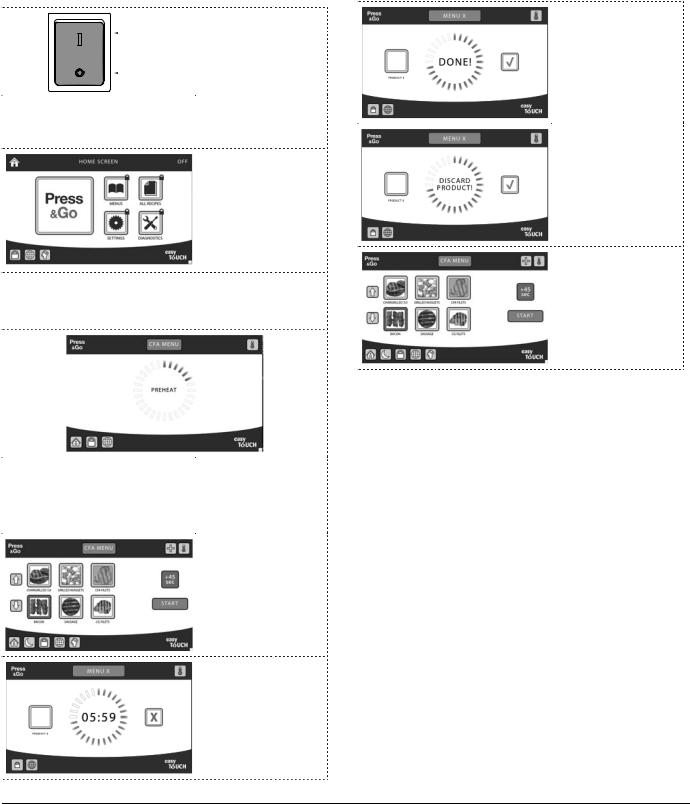
easyToUCH™ Home & Recipes Selector Pages
PRESS & GO - Used to access the preheat and cooking modes of the broiler.
SETTING - Used to change certain settings, such as date, time, and volume. Password protected.
DIAGNOSTICS - Select to view diagnostics screens. Password protected.
COOK CYCLE CHANGE - Used to adjust a recipe’s cook time or platen gap, if required to achieve
food safety and quality standards
LANGUAGE - Used to change the language of on-screen prompts. Only available if other languages have been pre-loaded on the broiler.
TEMPERATURE - Used to view the temperature settings and actual temperature in each zone.
MENUS - Used to add, edit, and delete Menus from the library. A Menu is a collection of cook recipes. Password protected.
RECIPES - Used to add, edit, and delete Recipes from the library. A Recipe consists of the cooking times, temperatures, and platen gaps for preparing a food item.
Password protected.
CLEAN MODE - Used to put the broiler into Clean mode. When the broiler is set to enforce the cleaning schedule, using the Clean Mode resets the cleaning counter
LOCK - Used to temporarily lock the touch screen. Locks the touch screen for six (6) seconds
to prevent accidental key presses when wiping the screen
HOME - Returns to the Home screen, the launching point for Cooking and programming modes. When the home screen is showing, the heaters are off.
SLEEP - Used to enter sleep mode. In Sleep mode, the platen lowers to conserve energy while the broiler is inactive
16 |
Document Number: G_EB_SM_CFABROILER (11/14) |
Section 3 |
Operation |
|
|
Clamshell Broiler Operating Modes:
The Clamshell Broiler operates in several modes accessible using the easyToUCH™ screen. All modes except for Sleep are selected from the Home screen. Clean mode may be selected from the Home screen or from Press & Go (cook) mode.
Press & Go mode is used to select menus, preheat the broiler, and cook recipes. The broiler will not preheat unless Press & Go has been selected. If multiple menus have been set up, select the appropriate menu to ensure the broiler preheats to the correct temperature.
The recipes stored by the broiler contain the cooking profiles (times, temperatures, and platen gaps) for various products.
If multiple menus have been set up, each may contain different recipes. To change the menu, select the “Menu”button at the top of the easyToUCH™ screen.
Sleep mode lowers the platen to conserve energy while the broiler is not in use while keeping it ready to start a cook cycle. The broiler may be configured to enter Sleep mode automatically after a period of inactivity, depending on the set up.
To enter Sleep mode manually, press the Sleep icon. The upper grate will lower, and the broiler will maintain the set temperatures.
To exit Sleep mode, select WAKE on the easyToUCH™ screen or press the GREEN push-button. The upper grate will rise and the broiler is ready to cook.
To stop the broiler from automatically entering Sleep mode, elect the red ‘X’on the easyToUCH™ screen or press the GREEN push-button. The upper grate will rise and the broiler is ready to cook.
Clean mode has two functions: it resets the cleaning counter and brings the broiler to the appropriate temperature for cleaning.
Note: check with the Chick-fil-A store manager to establish whether or not clean mode should be used.
By putting the broiler into Clean mode before cleaning the broiler, the cleaning reminder is reset to zero and the “Cleaning Reminder”prompts are suppressed. If the cleaning schedule is enforced, at some point the broiler must enter Clean mode before cooking may resume.
If a cleaning temperature has been set, Clean mode will bring the broiler to the set temperature prior to
starting the cycle. (A cleaning temperature may be specified if required by the cleaning procedure or cleaning chemicals.)
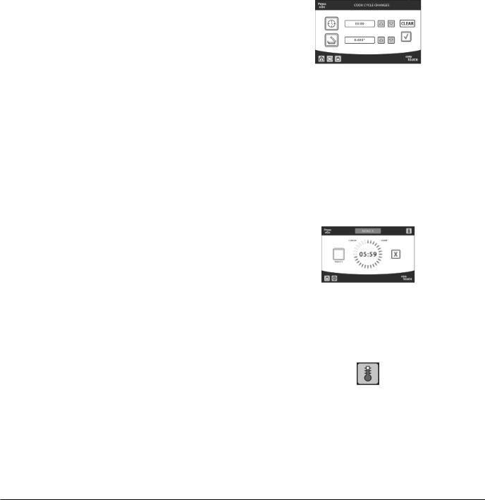
Cook Cycle Changes:
To ensure a quality product, the cook time and platen gap of a recipe may be changed prior to starting the cook cycle. Using the Cook Cycle Change screen, time can be added or subtracted from the end of a recipe and the platen gap can be opened or closed.
To change the cook cycle, select a recipe then press the “+”icon. The Cook Cycle Change screen appears. Using the up and down arrows, the time and the cook gap can be adjusted within certain limits. The changes made will stay in effect until they are changed again or cleared altogether. Changes to a recipe can also be cleared by pressing the “CLEAR”button on the Cook Cycle Change screen.
When a recipe has been changed, the recipe will have a “+”indicator on the Recipe Selector screen, and the cooking progress screen will show the adjustments to the recipe.
Temperatures:
The temperature screen shows the actual and the set point temperatures at each thermocouple, and whether that zone is heating or at temperature.
The temperature screen can be displayed by pressing the icon in the top right corner when cooking, cleaning, sleeping, or preheating. Press the Back arrow or Check mark to return to the previous screen.
Document Number: G_EB_SM_CFABROILER (11/14) |
17 |
Operation |
Section 3 |
|
|
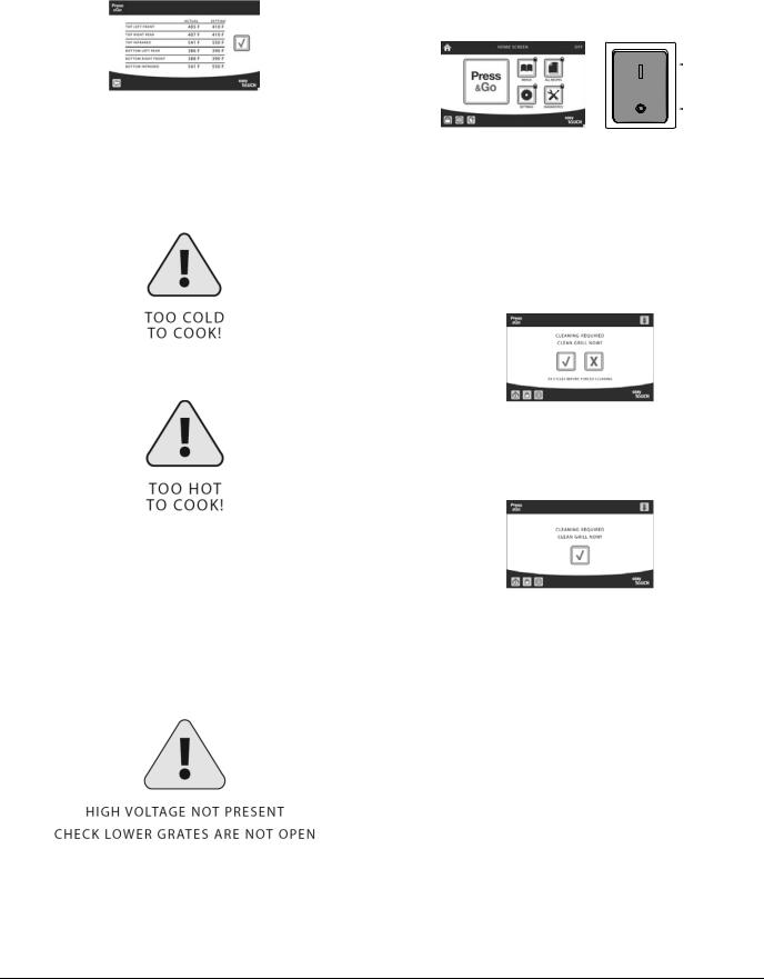
Warnings and Alerts:
Too Cool/Too Hot - If the broiler temperature is too cool to properly cook a recipe, a Too Cool to Cook message appears. The broiler will not allow the cook cycle to start until it has heated to the minimum required starting temperature.
Similarly, if the broiler is too hot, a Too Hot to Cook message is displayed while the broiler cools.
In either case, another recipe can be selected while waiting. If the broiler is at the right temperature to cook the newly selected recipe, cooking can start immediately.
Grates Open:
- For safety, an interlock switch cuts power to the heaters when the grates are open for ’routine cleaning. A warning message is displayed until the grates are returned to the operating position.
Note - if the main power is switched off, the power is already cut to the heater and easyToUCH™ screen, and the message does not appear.
Shutdown:
Press the Home icon to exit Press & Go mode and turn off the heaters.
|
ON |
+ |
OFF |
|
Fully power off the broiler and the easyToUCH™ screen using the main power switch.
Cleaning Reminders:
If a cleaning schedule has been set, a message will appear on the screen when cleaning is required based on the number of cook cycles. Select the tick mark
if the broiler will be cleaned immediately, or “X” to continue cooking.
If the broiler is set to enforce cleaning schedule and the cleaning reminder has been bypassed too many times, easyToUCH™ eventually displays the Cleaning Required screen (p. 32 from the wireframes).
18 |
Document Number: G_EB_SM_CFABROILER (11/14) |
Section 3 |
Operation |
|
|
START UP COOKING:
The easyToUCH™ screen display, layout and icons shown herein are for guidance purposes only and are not intended to be an exact representation of those displayed on the broiler.
ON |
1. Switch the broiler |
|
on using the main |
OFF |
power switch. |
2. The easyToUCH™ screen illuminates with the display briefly showing the software version (white text on black background).
3. When the Home screen appears, select Press & Go (Do not hit Press & Go until platen completes its homing sequence).
8.Cooking Done.
9. Discard product.
4. The broiler will start preheating using the |
10. Back to product |
temperatures from the selected menu and the preheat |
|
progress will be displayed. |
selection. |
5. Following preheat the broiler enters a soak period, allowing the temperature to stabilize throughout the upper and lower grates.
6. The broiler is ready to use when the Recipe Selector/ Ready to Cook screen is displayed..
7.Cooking time.
Document Number: G_EB_SM_CFABROILER (11/14) |
19 |

Operation |
Section 3 |
Cooking a Recipe
1. If the broiler has entered Sleep mode, select WAKE to raise the platen.
2. Select the recipe to cook.
3. If the broiler is at the wrong
temperature for the item selected, a “Too Hot”or “Too Cool” warning will appear.
|
Wait for the broiler to reach |
|
temperature or select a |
PLEASE |
different recipe. |
WAIT |
|
4. Lay product on the grates using the appropriate placement guidelines. For more detail see “CHICKEN / NUGGETS PRODUCT PLACEMENT”on page <?>
5. Press START or the GREEN push button to close the platen. Start the cycle. A progress ring and
countdown timer is displayed.
6. Start the cycle. A progress ring and countdown timer is displayed.
Note: Touching the red “ ”or pushing the green button during cooking stops the cook cycle, raises the platen, and displays a warning.
7. When the cook cycle has finished a “DONE” message is displayed, usually with an audible alarm. Remove the product and touch the green tick mark or press
the green button to acknowledge the “DONE”message.
Note: If the wrong recipe was selected, the recipe can be changed by stopping the cook cycle, acknowledging the warning, selecting the correct recipe, and pressing START or the GREEN push button again. Changes should be made within thirty (30)
seconds to avoid overcooking the product.
SAUSAGE or BACON: After a cook cycle has ended, if the cooked product fails to match the color requirements in the Test Quality Photos, cook the batch for an additional 45 seconds, by pressing the (+45 sec) icon. The platen will close and the product
will cook for the additional time.
20 |
Document Number: G_EB_SM_CFABROILER (11/14) |

Section 3 |
Operation |
|
|
Change to a Recipe Cook Cycle
1. Follow step from
1 to 6 from previous Press & Go.
2. Select recipe
3. Press  icon
icon
4. Make the necessary adjustments and save.
5. Clamshell broiler will make the necessary adjustments.
6. Ready to cook product.
Note: Modified recipe will show a plus (+) sign at the bottom right corner
Sleep Mode
1. Press & Go, (press)
2. Press  icon.
icon.
3. Press touch check mark  to continue or X
  to cancel.
4.Top platen will close, make sure no utensils on broiler.
5.Monitor will show sleeping time. Press touch the wake
option to start.
Document Number: G_EB_SM_CFABROILER (11/14) |
21 |
Operation |
Section 3 |
|
|
This procedure is used to cook marinated chargrilled filets, unmarinated Chick-fil-A filets and Grilled Nuggets on the Garland clamshell broiler.
Before you begin loading chicken, be sure to…
≠Verify that chicken has been thawed (35°-40°F / 1.7° - 4.4°C). Chicken that is not completely
thawed will not cook properly and may not reach the internal product temperature required to kill bacteria (165°F / 74°C).
≠Verify that enough chicken for current batch has been filleted.
≠Verify remaining shelf life and quality of chicken. Notify your Supervisor or Operator if any chicken has passed its expiration date.
≠Keep chicken refrigerated until immediately before grilling so it will maintain an internal product temperature of 40°F / 4.4°C or lower.
≠To avoid flavor transfer, use separate yellow trays for transferring chargrilled filets and Nuggets/ Chick-fil-A filets to broiler.
≠Store yellow tray (and yellow-handed tongs, if used) in refrigerator when not in use to help prevent bacterial growth.
Ingredients |
Quantities |
|
|
|
|
Raw filets (chargrilled |
Up to 10 per batch |
|
or Chick-fil-A filets) |
||
|
||
|
|
|
Raw Nuggets |
Up to 50 per batch |
Equipment/Items |
Used For |
|
Yellow food service |
Handling raw chicken |
|
gloves |
||
|
||
|
|
|
Yellow apron |
Working with raw chicken |
|
|
|
|
|
Transferring raw |
|
Designated yellow |
chargrilled filets to broiler |
|
trays |
Transferring raw Nuggets/ |
|
|
Chick-fil-A filets to broiler |
1.Remove chicken from refrigerator and place it on designated yellow tray.
2.Notify Boards person that filets are ready for cooking. This will alert Boards person to prepare broiler.
3.Load raw chicken onto broiler.
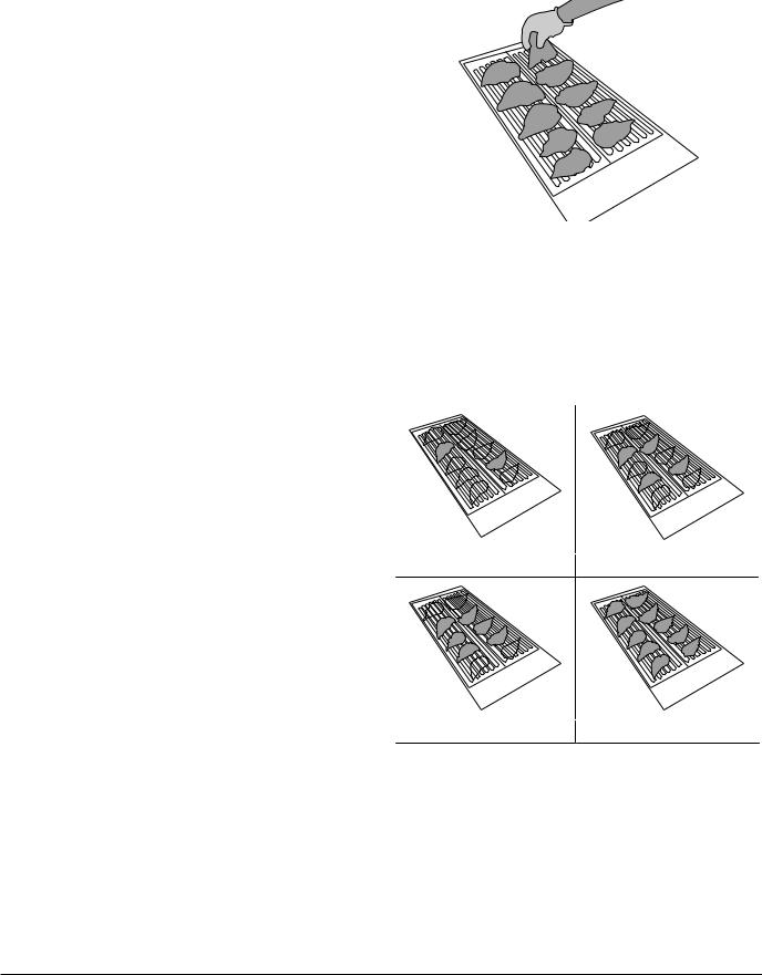
•Fillet:
—Ensure that oil has been applied to lower and upper broiler grates.
—Load up to 10 filets on broiler (5 rows of 2 filets), working from front to back.
—Position filets so they are centered on left half or right half of lower broiler grate (not overlapping outer or inner edges of broiler grate).
2 |
|
4 |
|
3 |
|
|
1 |
|
|
2 |
|
|
|
|
|
|
1 |
Load of 2 filets |
Load of 4 filets |
||
|
|
10 |
|
|
|
9 |
|
|
6 |
8 |
|
5 |
4 |
7 |
6 |
|
|||
3 |
2 |
5 |
4 |
|
1 |
3 |
2 |
|
|
|
1 |
Load of 6 filets |
Load of 10 filets |
—Place filets with smooth side down because best broiler marks will show on smooth side.
—Point tips of filets to outside of broiler, so that thickest portion of filet is in center of broiler.
—Make sure filets do not touch.
•Nuggets:
—Ensure that Nugget rack screen are in place, on lower broiler grate and that oil has been applied to screen and upper broiler grate.
22 |
Document Number: G_EB_SM_CFABROILER (11/14) |
 Loading...