


Gas/Electric Dual Side Grill
M(E/G)-1P, M(E/G)-2P, M(E/G)-3PX
Installation, Operation and Maintenance Manual
Please read all sections of this manual and retain for future reference.
For your safety:
Post in a prominent location, instructions to be followed in the event the user smell gas. This information shall be obtained by consulting your local gas supplier.
Original Instructions
Part #: GAR_IOM_4600921_Rev5
THIS PAGE INTENTIONALLY LEFT BLANK

Safety Notices
DEFINITIONS
 DANGER
Indicates a hazardous situation that, if not avoided, will result in death or serious injury. This applies to the most extreme situations.
Warning
Indicates a hazardous situation that, if not avoided, could result in death or serious injury.
Caution
Indicates a hazardous situation that, if not avoided, could result in minor or moderate injury.
Notice
Indicates information considered important, but not hazard-related (e.g. messages relating to property damage).
NOTE: Indicates useful, extra information about the procedure you are performing.
DISCLAIMERS
Warning
Only trained and authorized service personnel or store manager should access the service screens. If changes to these settings are made incorrectly they will cause the unit to malfunction.
Caution
Maintenance and servicing work other than cleaning as described in this manual must be done by an authorized service personnel.
 DANGER
Do not install or operate equipment that has been misused, abused, neglected, damaged, or altered/ modified from that of original manufactured specifications.
 DANGER
All utility connections and fixtures must be maintained in accordance with local and national codes.
 DANGER
It is the responsibility of the equipment owner to perform a Personal Protective Equipment Hazard Assessment to ensure adequate protection during maintenance procedures.
 DANGER
The on-site supervisor is responsible for ensuring that operators are made aware of the inherent dangers of operating this equipment.
NOTE: Proper installation, care and maintenance are essential for maximum performance and trouble-free operation of your equipment. Visit our website https://clamshell.garland-group.com for manual updates, translations, or contact information for service agents in your area.
Warning
Do Not Store Or Use Gasoline Or Other Flammable Vapors Or Liquids In The Vicinity Of This Or Any Other Appliance. Never use flammable oil soaked cloths or combustible cleaning solutions, for cleaning.
Warning
Do not store combustible materials on the appliance.
Warning
Warning labels mounted directly on the equipment must be observed at all times and kept in a fully legible condition.
Warning
Read this manual thoroughly before operating, installing or performing maintenance on the equipment. Failure to follow instructions in this manual can cause property damage, injury or death.
Warning
This appliance is not intended for use by persons (including children) with reduced physical, sensory or mental capabilities, or lack of experience and knowledge, unless they have been given supervision concerning use of the appliance by a person responsible for their safety. Do not allow children to play with this appliance.
Notice
Routine adjustments and maintenance procedures outlined in this manual are not covered by the warranty.
Warning
This product contains chemicals known to the State of California to cause cancer and/or birth defects or other reproductive harm. Operation, installation, and servicing of this product could expose you to airborne particles of glass-wool or ceramic fibers, crystalline silica, and/or carbon monoxide. Inhalation of airborne particles of glass-wool or ceramic fibers is known to the State of California to cause cancer. Inhalation of carbon monoxide is known to the State of California to cause birth defects or other reproductive harm.
LOCATION
Warning
Two or more people or a lifting device are required to lift this appliance.
Warning
To avoid instability the installation area must be capable of supporting the combined weight of the equipment and product. Additionally the equipment must be level side to side and front to back.
Warning
No structural material on the appliance should be altered or removed to accommodate placement of the appliance under a hood.
Warning
Be aware of the red mark in the threaded steem caster to indicated the maximum adjustment. Adjusting above the red mark could cause the caster to fail & the unit to tip. For more information see installation section 2.
Warning
The appliance must be isolated from the gas supply piping system by closing its individual manual shutoff valve during any pressure testing of the gas supply piping system at test pressures equal to or less than ½ psi (3.5 kPa).
Caution
This equipment must only be operated under an approved hood system in accordance with local regulations in force. This unit is intended for indoor use only.
ELECTRICAL
 DANGER
Check all wiring connections, including factory terminals, before operation. Connections can become loose during shipment and installation.
 DANGER
Do not operate any appliance with a damaged/pinched cord or plug. All repairs must be performed by a qualified service company.
 DANGER
Failure to disconnect the power at the main power supply could result in serious injury or death. The power switch DOES NOT disconnect all incoming power.
 DANGER
Copper wire suitable for at least 75°C (167°F) must be used for power connections.
Warning
This appliance must be grounded and all field wiring must conform to all applicable local and national codes. Refer to rating plate for proper voltage. It is the responsibility of the end user to provide the disconnect means to satisfy the authority having jurisdiction.
Warning
Do not use electrical appliances or accessories other than those supplied by the manufacturer.
Warning
This equipment must be positioned so that the plug is accessible unless other means for disconnection from the power supply (e.g., circuit breaker or disconnect switch) is provided.
Warning
Disconnect electric power at the main power disconnect for all equipment being serviced. Observe correct polarity of incoming line voltage. Incorrect polarity can lead to erratic operation.
Warning
Never touch anything that runs on electricity when your hands are wet.

CODE
Warning
Authorized Service Representatives are obligated to follow industry standard safety procedures, including, but not limited to, local/national regulations for disconnection / lock out / tag out procedures for all utilities including electric, gas, water and steam.
Warning
Foranapplianceequippedwithcasters,(1)theinstallation shall be made with a connector that complies with the Standard for Connectors for Movable Gas Appliances ANSI Z21.69 • CSA 6.16, and a quick-disconnect device that complies with the Standard for Quick-Disconnect Devices for Use With Gas Fuel, ANSI Z21.41 • CSA 6.9, (2) adequate means must be provided to limit the movement of the appliance without depending on the connector and the quick-disconnect device or its associated piping to limit the appliance movement and (3) the location(s) where the restraining means may be attached to the appliance shall be specified.
DAMAGE
 DANGER
Improper installation, adjustment, alteration, service, or maintenance of this appliance or installation of a damaged appliance can result in DEATH, INJURY, EQUIPMENT DAMAGE, and void the warranty. NEVER install damaged appliances, equipment, or accessories.
ALWAYS have installation and service performed by trained and authorized personnel.
Caution
Pouring water or ice on a hot heating elements/heated surfaces will cause damage..
Warning
Pinch Hazard. Keep hands and tools clear from the area above the platens when platens are in motion towards the exhaust hood. Be aware that adjacent platens may unexpectedly move at any time. “Turn Grill Off” at main switch when cleaning platens as there can be an unexpected movement of the platens
CLEARANCE
Caution
Do not block the supply and return air vents or the air space around the air vents. Keep plastic wrappings, paper, labels, etc. from being airborne and lodging in the vents. Failure to keep the air vents clear will result in unsatisfactory operation of the system.
Caution
Do not position the air intake vent near steam or heat exhaust of another appliance.
Warning
Slipping Hazard: Grease from food products will splatter. The areas surrounding the grill are a slipping hazard due to the splatter zone. Clean the area surrounding the grill regularly. The grill may be slippery. Ensure floor area is clean. Care needs to be taken as equipment may be hot.
Warning
Failure to maintain required clearances and additional distances as needed can result in INJURY and EQUIPMENT DAMAGE.
Consult manufacturers’ literature, and sales and service agencies as needed.
 DANGER
To reduce the risk of fire, the equipment is to be installed in non-combustible surroundings only, with no combustible material within 18” (457 mm) of the sides, front or rear of the appliance or within 40 “ (1 m) above the appliance. The appliance is to be mounted on floors of noncombustible construction with noncombustible flooring and surface finish and with no combustible material against the underside or on noncombustible slabs or arches and have no combustible material against the underside. Such construction shall in all cases extend not less than 12” (305 mm) beyond the equipment on all sides.
 DANGER
Risk of fire/shock. All minimum clearances must be maintained. Do not obstruct vents or openings.
Warning
Pinch Hazard. Ensure a minimum of 1" clearance between the hood and the uppermost position of the platen arm. To reduce the risk of chrushing injuries between platen & hood.

CLEANING
Caution
Ensure platens are down, in closed position, when moving grill. Follow the procedure to avoid potential damage, loss of calibration on the platen, and error messages.
Caution
Never use an acid based cleaning solution on exterior panels! Many food products have an acidic content, which can deteriorate the finish. Be sure to clean the stainless steel surfaces of ALL food products.
Caution
Do not use caustic cleaners on any part of the equipment or equipment cavity . Use mild, non abrasive soaps or detergents, applied with a sponge or soft cloth. Never use sharp implements or harsh abrasives on any part of the equipment.
Warning
When cleaning interior and exterior of unit, care should be taken to avoid front power switch and the power cord(s). Keep water and/or cleaning solutions away from these parts.
Warning
Turn grill off and unplug the unit before cleaning the side/back panels. Do not remove any panel during cleaning.
Warning
Interior cleaning must be performed by a qualified service technician only.
Warning
Never use a high-pressure water jet for cleaning or hose down or flood interior or exterior of units with water. Do not use power cleaning equipment, steel wool, scrapers or wire brushes on stainless steel or painted surfaces.
Caution
Use a commercial-grade cleaner formulated to effectively clean and sanitize food contact surfaces. Read the directions for use and precautionary statements before use. Particular attention must be paid to the concentration of cleaner and the length of time the cleaner remains on the food-contact surfaces.
Warning
Be aware that adjacent platens may unexpectedly move at any time.“Turn Grill Off”at main switch when cleaning platens as there can be an unexpected movement of the platens.
PERSONAL PROTECTION
 DANGER
All utilities (gas, electric, water and steam) must be OFF to all equipment and locked out of operation according to OSHA approved practices during servicing. Always allow unit to cool.
 DANGER
Use appropriate safety equipment during installation and servicing.
 DANGER
Never stand on the unit! They are not designed to hold the weight of an adult, and may collapse or tip if misused in this manner.
 DANGER
Keep power cord AWAY from HEATED surfaces. DO NOT immerse power cord or plug in water. DO NOT let power cord hang over edge of table or counter.
Warning
DO NOT use the unit for storage. DO NOT leave paper products, cooking utensils, or food in the unit when not in use.
Warning
Allow heated equipment to cool down before attempting to clean, service or move. Unit must be cool to touch and disconnected from power source.
Warning
Always wear some type of protective covering on your hands and arms when opening the unit.
Warning
Steam can cause serious burns. Always wear some type of protective covering on your hands and arms when opening the unit. When platen is Lifting, move away face and body from the escaping steam.

Warning
Remove all removable panels before lifting and installing.
Warning
Do not contact moving parts.
Warning
When using cleaning fluids or chemicals, rubber gloves and eye protection (and/or face shield) must be worn.
Warning
Use caution when handling all metal surface edges of the equipment.
Warning
This equipment is intended for indoor use only. Do not install or operate this equipment in outdoor areas.
Warning
All covers and access panels must be in place and properly secured, before operating this equipment.
Warning
Do not spray aerosols in the vicinity of this appliance while it is in operation.
Warning
Risk of burns from high temperatures. You may get burnt if you touch any of the parts during cooking. Surfaces close to the cooking surface including side panels may get hot enough to burn skin. Use extreme caution to avoid coming in contact with hot surfaces or hot grease. Wear personal protective equipment.
Warning
When checking for burner ignition or performance, do not get too close to the burners. Slow ignition can cause possible flashback, increasing the potential for facial and body burns.
Warning
This appliance must be installed with sufficient ventilation to prevent the occurrence of unacceptable concentrations of substances harmful to the health of personnel in the room in which it is installed.
Warning
Hazard. Keep hands and tools clear from the area above the platens when platens are in motion towards the exhaust hood. Be aware that adjacent platens may unexpectedly move at any time. “Turn Grill Off” at main switch when cleaning platens as there can be an unexpected movement of the platens.
Warning
Slipping Hazard: Grease cans must be properly installed before use. Improper installation will result in grease on the floor which will create a slipping hazard. Ensure grease cans are emptied and cleaned as needed to prevent grease from overflowing onto the floor. The grill may be slippery. Ensure floor area is clean. Care needs to be taken as equipment may be hot
Warning
Pinch Hazard. Keep hands and toolsclear of area between platen and grill plate when platens are in motion. Be aware that adjacent platens may unexpectedly move at any time. “Turn Grill Off” at main switch when cleaning platens as there can be an unexpected movement of the platens.
Warning
Post in a prominent location, instructions to be followed in the event the user smell gas. This information shall be obtained by consulting your local gas supplier.

Table of Contents
Safety Notices
Definitions................................................................................................................................................. |
3 |
Disclaimers................................................................................................................................................ |
3 |
Location ..................................................................................................................................................... |
4 |
Electrical .................................................................................................................................................... |
4 |
Damage...................................................................................................................................................... |
5 |
Clearance................................................................................................................................................... |
5 |
Section 1
General Information
Read This Manual ............................................................................................................. |
10 |
Unit Inspection ................................................................................................................. |
10 |
Model Numbers................................................................................................................ |
10 |
Serial Plate Numbers........................................................................................................ |
10 |
Warranty Statement......................................................................................................... |
11 |
Shipping Damage Claim Procedure................................................................................ |
11 |
Items included with the purchase of your new grill from manufacturer:.................... |
13 |
3 Platen Dimensions Specification ................................................................................. |
14 |
2 + 1 Platen Single Chassis Dimensions Specification .................................................. |
15 |
2 Platen Dimensions Specification ................................................................................. |
16 |
1 Platen Dimensions Specification ................................................................................. |
17 |
Electrical Input Specification - WYE, (CE - gas models) ................................................. |
18 |
Electrical Input Specification - Delta (gas models)........................................................ |
18 |
Electrical Input Specification - WYE (CE - electric models)............................................ |
19 |
Electrical Input Specification - Delta (electic models)................................................... |
20 |
Gas Input Specification.................................................................................................... |
21 |
Section 2
Installation
Removing Grill From Wood Crate.................................................................................... |
21 |
Transporting Grill To Location......................................................................................... |
22 |
Location. ........................................................................................................................... |
22 |
Clearance Requirements.................................................................................................. |
22 |
Leveling............................................................................................................................. |
22 |
Exhaust Hood Requirements........................................................................................... |
22 |
Appliances Equipped with Casters. ................................................................................ |
23 |
Casters Adjustment Procedure. ...................................................................................... |
23 |
Temporary Storage .......................................................................................................... |
24 |
Gas Connector Requirements.......................................................................................... |
24 |
National Codes Requirements......................................................................................... |
25 |
Installation store responsibilities. .................................................................................. |
25 |
Restraining device installation Procedure. .................................................................... |
25 |
“Desi Pak” bags from the grill. ........................................................................................ |
26 |
Removing “Desi Pak” bags from the grill. ...................................................................... |
26 |
Gas Connections, and Pipe Sizing. ................................................................................. |
26 |
Mennekes 7 Pins Option. ................................................................................................. |
28 |
Flue Upper Rear Panel Install Instruction....................................................................... |
29 |
One & Two Platen Connections Procedure. ................................................................... |
30 |
Startup Procedure............................................................................................................ |
33 |
Section 3
Operation
Sequence of Operation .................................................................................................... |
34 |
easyToUCH™ Controller ................................................................................................... |
35 |
8 |
Part #: GAR_IOM_4600921_Rev5 |

Table of Contents (continued) |
|
Home Screen, Recipe Selector Screen & Icons ......................................................................... |
35 |
On Screen Warnings and Alerts Messages................................................................................. |
36 |
Operations Overview......................................................................................................................... |
36 |
easyTOUCH™ Procedures................................................................................................. |
37 |
Start Up & Insert Installation Date................................................................................................. |
37 |
Preheat.................................................................................................................................................... |
37 |
Cook A Recipe....................................................................................................................................... |
38 |
Check Temperatures........................................................................................................................... |
38 |
Canceling a Cook Cycle ..................................................................................................................... |
38 |
Create New Recipe.............................................................................................................................. |
39 |
setting up for 2 stage cooking, “add cheese”............................................................................. |
41 |
Create a New Menu ............................................................................................................................ |
42 |
Turn Menus OFF or ON...................................................................................................................... |
42 |
Change Cook Time/Gap.................................................................................................................... |
43 |
Time & Gap Adjustment Limits....................................................................................................... |
43 |
Activate Sleep Mode Manually....................................................................................................... |
44 |
Volume Adjustment ........................................................................................................................... |
44 |
Hood Height Adjustment................................................................................................................. |
45 |
Language Selection............................................................................................................................ |
45 |
Clean Settings....................................................................................................................................... |
46 |
Cleaning Reminders ........................................................................................................................... |
47 |
Shutdown .............................................................................................................................................. |
47 |
Auto Level Settings Calibration...................................................................................................... |
47 |
Patty Placement................................................................................................................................... |
50 |
Factory default setting - product menu, World........................................................................ |
53 |
Factory default setting - product menu, Canada, Australia & UK. ..................................... |
54 |
Factory default setting - product menu, Japan & Hong Kong. .......................................... |
55 |
Section 4 |
|
Maintenance |
|
Cleaning the easyToUCH™ controller.............................................................................. |
56 |
Cleaning the Stainless Steel Panels ................................................................................ |
56 |
Cleaning During Operation ............................................................................................. |
56 |
Daily Cleaning .................................................................................................................. |
57 |
Moving the Grill................................................................................................................ |
60 |
Section 5 |
|
Troubleshooting |
|
Cooking Issues.................................................................................................................. |
61 |
Undercooked product....................................................................................................................... |
61 |
Undercooked product only at front of grill................................................................................ |
61 |
Overcooked product.......................................................................................................................... |
61 |
Temperature Issues .......................................................................................................... |
62 |
Grill or platen too hot ........................................................................................................................ |
62 |
Grill or platen too cool....................................................................................................................... |
62 |
Unable to reach or maintain temperature ................................................................................. |
62 |
User Interface Issues ........................................................................................................ |
62 |
No sound................................................................................................................................................ |
62 |
Screen locked out, frozen, non-responsive to touch.............................................................. |
62 |
Touch screen rebooting.................................................................................................................... |
62 |
Unable to read USB............................................................................................................................. |
62 |
Unable to load USB files.................................................................................................................... |
62 |
Section 6 |
|
Tools & Cleaning Supplies |
|
Cleaning Supplies............................................................................................................. |
63 |
Part #: GAR_IOM_4600921_Rev5 |
9 |

Section 1
General Information
Read This Manual
Garland Commercial Equipment (GCE) developed this manual as a reference guide for the owner/operator and installer of this equipment. Please read this manual before installation or operation of the machine. A qualified service technician must perform installation and start-up of this equipment, consult Section 5 within this manual for service assistance.
If you cannot correct the service problem, call your Service Agent or Distributor. Always have your model and serial number available when you call.
Your Service Agent ____________________________
Service Agent Telephone Number _________________
Your Local GCE Distributor ______________________
Distributor Telephone Number ____________________
Model Number _______________________________
Serial Number ________________________________
Installation Date ______________________________
Unit Inspection
Thoroughly inspect the unit upon delivery. Immediately report any damage that occurred during transportation to the delivery carrier. Request a written inspection report from a claims inspector to document any necessary claim
Model Numbers
This manual covers the following models:
a.M(G/E)-1P (1Platen)
b.M(G/E)-2P (2 Platen)
c.M(G/E)-3PX (2+1single chassis).
Type |
|
|
|
|
|
|
|
|
|
|
Model Size |
|||||
|
|
|
|
|
|
|
|
|
|
|||||||
Model Prefix |
|
|
|
|
|
|
|
|
|
|
|
|
|
|||
|
|
|
|
|
|
|
|
|
|
|
|
|
|
|
||
|
|
|
|
|
|
|
|
|
|
|
|
|
|
|
|
|
McDonad’s |
|
M |
|
|
|
G |
|
- |
|
2P |
|
1P:12” width |
||||
|
|
|
|
|
|
|||||||||||
|
|
|
|
|
|
|
|
|
|
|
|
|
|
|
||
|
|
|
|
|
|
|
|
|
|
|
|
|||||
|
|
|
|
|
|
|
|
|
|
|
|
|||||
|
|
|
|
|
|
|
|
|
|
|
|
|
|
|
|
|
G: Gas |
|
|
|
|
|
|
2P:24” width |
|||||||||
E: Electric |
|
|
|
|
|
|
|
|
|
3PX:38” width |
||||||
|
|
|
|
|
|
|
|
|
|
|
|
|
|
|
|
|
Serial Plate Numbers
The serial plate is affixed to the lower left corner of the right panel and a serial sticker on front edge of the chassis. Important information such as the unit’s model number, serial number, and electrical/gas specifications can be found on the serial plate.
10 |
Part #: GAR_IOM_4600921_Rev5 |
Section 1 |
General Information |
|
|
Warranty Statement
This warranty covers defects in material and workmanship under normal use providing that:
a.the equipment has not been accidentally or intentionally damaged, altered or misused.
b.the equipment is properly installed, adjusted, operated and maintained in accordance with national and local codes and in accordance with the installation instructions provided with this product.
c.the warranty serial number affixed to the appliance by us has not been defaced, obliterated or removed.
d.can acceptable report for any claim under this warranty is supplied to us.
The equipment warranty coverage remains in force for two (2) years, (parts and labor), from the date the equipment is put into operation.
The Garland Group agrees to repair or replace, at it’s option, any part that proves to be defective in material or workmanship at no charge for the part or normal labor.
We assume no responsibility for installation, adjustments, diagnosis, or normal maintenance such as: lubrication of springs or valves. We exclude failures caused by erratic voltage or gas supplies.
We assume no responsibility for travel costs beyond 100 miles round trip, travel other than overland, and overtime costs of repair.
We exclude broken glass, paint and porcelain finish, surface rust, gasket material, ceramic material, light bulbs and fuses from normal coverage.
We exclude damage or dysfunction caused by fire, flood, and like “Acts of God” that are beyond the control of The Garland Group.
The Garland Group’s liability on a claim of warranty shall not exceed the price of the material and/or service, which caused the claim.
This warranty is limited and is in lieu of all other warranties, expressed or implied. The Garland Group, our employees, or our agents shall not be held liable for any claims of personal injury or consequential damage or loss.
This warranty gives you specific legal rights, and you may have other rights which vary from state to state.
Shipping Damage Claim Procedure
Please note that the Garland equipment was carefully inspected and packed by skilled personnel before leaving the factory. The transportation company assumes full responsibility for safe delivery upon acceptance of the equipment. What to do if the equipment arrives damaged:
1.File a claim immediately regardless of the extent of damage.
2.Be sure to note, “visible loss or damage,” on the freight bill or express receipt and have the person making the delivery sign it.
3.Concealed loss or damage: if damage is unnoticed until the equipment is unpacked, notify the freight company immediately, (within 15 days), and file a concealed damage claim.
Part #: GAR_IOM_4600921_Rev5 |
11 |
General Information |
Section 1 |
|
|
|
|
4 |
|
10 |
|
|
|
|
|
|
2 |
3 |
|
14 |
|
|
or |
|
11 |
|
|
4 |
|
|
|
|
|
|
15 |
|
|
5 |
|
16 |
|
|
|
|
|
1 |
|
|
|
|
|
|
17 |
|
|
6 |
7 |
9 |
12 |
13 |
|
|
|
|
8
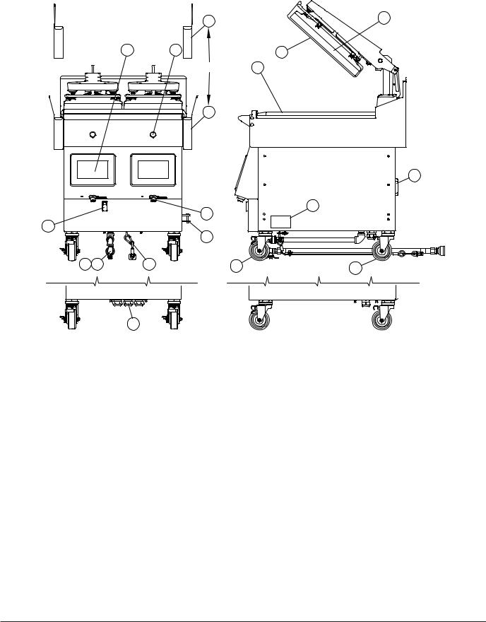
1.On/Off Power Switch.
2.easyToUCH™ Touch sensitive controls for easy operation.
3.Green Push Button.
•press to start cook.
•press and hold to abort.
4.Grease Buckets.
•with straight sides to save space.
•with flared sides to accommodate optional tool holders.
5.USB Ports - for easyToUCH.
6.Incoming gas manifold (gas models only).
7.Main gas shut off (gas models only). Supply with optional flexible hose connection assembly.
8.Main Electric Power Cables and Plugs.
9.Restraining device assembly (gas models only)
10.Platen - providing double-side cooking. Each platen can be controlled separately.
11.Grill Plate - cooking surface with three (3) Independently controlled heaters per cook zones.
12.Front Casters - height adjustable swivel casters, with brakes and swivel lock pins.
13.Rear Casters - height adjustable swivel casters and swivel lock pins (without brakes).
14.Release Material Sheet - non-stick surface for ease of operation and cleaning.
15.Circuit Breaker(s)
16.Rating Plate location. - Important information such as the unit’s model number, serial number, and electrical specifications can be found on the serial plate.
Note: Serial number also can be found in the control in the “Diagnostic Menu” in the “Revision” screen.
17.Platen connection brackets (optional)
12 |
Part #: GAR_IOM_4600921_Rev5 |

Section 1 |
General Information |
|
|
Items included with the purchase of your new grill from manufacturer:
1.One Grill 1 platen (gas & electric) includes the following list;
1 PLATEN
Part # |
Description |
Qty |
|
|
|
4527294 |
Release Material Sheet Clips |
3 |
|
|
|
4600722 |
Release Material Sheet Hanger |
1 |
|
|
|
4600866 |
Release Material Sheet (box) |
1 |
|
|
|
4600415 |
Grease Drawer Slide LT |
1 |
|
|
|
4600416 |
Grease Drawer Slide RT |
1 |
|
|
|
4600411 |
Grease Drawer Buckets - right side |
1 |
|
|
|
4600418 |
Grease Drawer Buckets - left side |
1 |
|
|
|
1838701 |
Platen Levelling Tool |
1 |
|
|
|
4532089 |
Service Wrench |
1 |
|
|
|
4602107 |
Garland Grill Start Up Form |
1 |
|
|
|
4600921 |
Installation Operation Manual |
1 |
|
|
|
NOTE: Quantity may vary according to the model.
2.One Grill 2 platen (gas & electric) includes the following list;
2 PLATEN
Part # |
Description |
Qty |
|
|
|
4527294 |
Release Material Sheet Clips |
6 |
|
|
|
4600722 |
Release Material Sheet Hanger |
2 |
|
|
|
4600866 |
Release Material Sheet (box) |
1 |
|
|
|
4600415 |
Grease Drawer Slide LT |
1 |
|
|
|
4600416 |
Grease Drawer Slide RT |
1 |
|
|
|
4600411 |
Grease Drawer Buckets - right side |
1 |
|
|
|
4600418 |
Grease Drawer Buckets - left side |
1 |
|
|
|
1838701 |
Platen Levelling Tool |
1 |
|
|
|
4532089 |
Service Wrench |
1 |
|
|
|
4602107 |
Garland Grill Start Up Form |
1 |
|
|
|
4600921 |
Installation Operation Manual |
1 |
|
|
|
NOTE: Quantity may vary according to the model.
3.One Grill 2+1 platen (gas & electric) included the following list, except countries mentioned
2+1 PLATEN
Part # |
Description |
Qty |
|
|
|
4527294 |
Release Material Sheet Clips |
9 |
|
|
|
4600722 |
Release Material Sheet Hanger |
3 |
|
|
|
4600866 |
Release Material Sheet (box) |
1 |
|
|
|
4600415 |
Grease Drawer Slide LT |
1 |
|
|
|
4600416 |
Grease Drawer Slide RT |
1 |
|
|
|
4600417 |
Grease Drawer Slide Mid |
1 |
|
|
|
4600411 |
Grease Drawer Buckets - right side |
1 |
|
|
|
4600427 |
Grease Drawer Buckets - Middle side |
1 |
|
|
|
4600418 |
Grease Drawer Buckets - left side |
1 |
|
|
|
4601744 |
One & Two Hdwe Pkg |
1 |
|
|
|
1838701 |
Platen Levelling Tool |
1 |
|
|
|
4532089 |
Service Wrench |
1 |
|
|
|
4602107 |
Garland Grill Start Up Form |
1 |
|
|
|
4600921 |
Installation Operation Manual |
1 |
|
|
|
NOTE: Quantity may vary according to the model.
4.One Grill 2+1 platen (gas & electric) single chassis included the following list, except countries mentioned
2+1 PLATEN SINGLE CHASSIS
Part # |
Description |
Qty |
|
|
|
4527294 |
Release Material Sheet Clips |
9 |
|
|
|
4600722 |
Release Material Sheet Hanger |
3 |
|
|
|
4600866 |
Release Material Sheet (box) |
1 |
|
|
|
4600415 |
Grease Drawer Slide LT |
1 |
|
|
|
4600416 |
Grease Drawer Slide RT |
1 |
|
|
|
4600417 |
Grease Drawer Slide Middle |
1 |
|
|
|
4600411 |
Grease Drawer Buckets - right side |
1 |
|
|
|
4600418 |
Grease Drawer Buckets - left side |
1 |
|
|
|
1838701 |
Platen Levelling Tool |
1 |
|
|
|
4532089 |
Service Wrench |
1 |
|
|
|
4602107 |
Garland Grill Start Up Form |
1 |
|
|
|
4600921 |
Installation Operation Manual |
1 |
|
|
|
NOTE: Quantity may vary according to the model.
Items NOT INCLUDED from the manufacturer:
1.Any electrical cords needed for application.
2.Any flue box needed for application.
3.Any extra grease buckets or grease rails needed for application.
THE FOLLOWING INSTALLATION PROCEDURE CAN BE PERFORMED BY A:
•Factory authorized service center
•An approved installation person approved by Garland.
•Licensed installer contracted by purchaser of grill.
•Contact local Garland Factory Authorized Service Center for more details.
Part #: GAR_IOM_4600921_Rev5 |
13 |

General Information |
Section 1 |
|
|
3 Platen Dimensions Specification
Model: M(E/G)-3P |
|
TOP HEATER |
|
1.255in |
11.500in |
||
|
|
292.1mm |
|
|
|
31.9mm |
|
|
|
FOR GAS UNITS ONLY |
|
|
|
|
TOP HEATER |
|
|
34.505in |
17.500in |
|
|
444.5mm |
|
|
|
876.4mm |
|
|
|
GRILL PLATE |
|
|
|
|
22.000in |
|
|
|
558.8mm |
|
540.4mm |
|
|
|
MIN |
|
GRILL PLATE |
|
|
|
35.750in |
2.170in |
|
908.1mm |
|
|
|
||
55.1mm |
|
|
|
|
19.250in |
|
TOP VIEW |
|
489mm |
|
|
|
|
|
|
|
|
42° |
36.979in |
|
|
MAX |
939.3mm |
|
|
19.005in |
|
|
|
482.7mm |
|
|
|
MAX |
|
|
|
45.528in |
|
|
|
1156.4mm |
|
|
|
MAX |
|
|
|
|
32.941in |
35.574 MAX TO 29.887 MIN |
903.6 MAX TO 759.1 MIN |
|
836.7mm |
23.978in |
|
||
609mm |
|
||
|
|
||
|
1.726in |
|
43.8mm |
GAS CONNECTION |
FOR GAS UNITS ONLY |
|
Model |
|
Height* |
|
Width** |
Depth |
|||
|
|
|
|
|
|
|
|
|
|
|
|
|
|
|
|
34.5 in - without flue |
876 mm - without flue |
M(E/G)-3P |
32 in |
|
812 mm |
36 in |
|
914 mm |
35.8in - with flue |
909mm - with flue |
|
|
|
|
|
|
|
(gas models) |
(gas models) |
* Height not including caster ** Without grease buckets.
14 |
Part #: GAR_IOM_4600921_Rev5 |
Section 1 |
General Information |
|
|
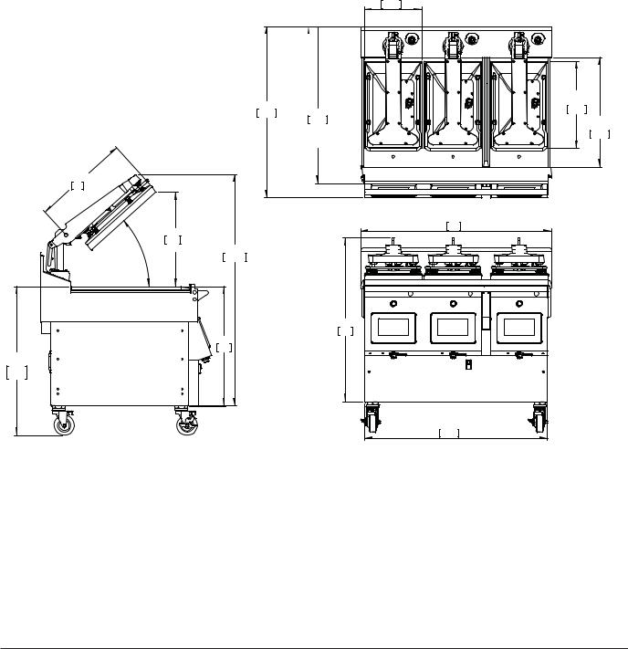
2 + 1 Platen Single Chassis Dimensions Specification
Model: M(E/G)-3PX
|
|
|
|
TOP HEATER |
|
|
|
|
11.50 |
|
|
|
|
292.1 |
|
|
|
|
TOP HEATER |
|
|
34.27 |
|
17.50 |
|
|
31.51 |
444.5 |
|
|
|
870.5 |
||
|
|
800.4 |
GRILL PLATE |
|
|
|
|
||
|
|
|
WITH TOWEL BAR |
22.00 |
|
|
|
558.8 |
|
|
|
|
& |
|
|
|
|
FRONT PANEL REMOVED |
|
19.25 |
|
|
|
|
489 |
|
|
|
|
|
|
|
|
38.23 |
|
18.96 |
|
|
971 |
|
|
|
|
|
42° |
481.5 |
|
|
|
MAX |
MAX. |
46.40 |
|
|
|
1178.6 |
|
|
|
. |
|
|
|
|
|
|
|
32.91 |
|
|
|
23.98 |
836 |
|
|
|
|
|
|
35.50 |
|
609 |
|
|
|
|
|
|
|
29.88 |
|
|
|
|
901.7 |
|
|
|
|
758.8 |
|
|
|
|
|
|
|
|
36.66 |
|
|
|
|
931.1 |
Model |
|
Height* |
|
Width** |
Depth |
|||
|
|
|
|
|
|
|
|
|
|
|
|
|
|
|
|
34.5 in - without flue |
876 mm - without flue |
M(E/G)-3PX |
32 in |
|
812 mm |
38 in |
|
965.2 mm |
35.8in - with flue |
909mm - with flue |
|
|
|
|
|
|
|
(gas models) |
(gas models) |
* Height not including caster ** Without grease buckets.
Part #: GAR_IOM_4600921_Rev5 |
15 |

General Information |
Section 1 |
|
|
2 Platen Dimensions Specification |
|
|
|
|
Model: M(E/G)-2P |
|
|
|
|
|
|
|
TOP HEATER |
|
|
|
1.255in |
11.500in |
|
|
|
292.1mm |
|
|
|
|
31.9mm |
|
|
|
|
FOR GAS UNITS ONLY |
|
|
|
|
34.505in |
TOP HEATER |
|
|
|
17.500in |
|
|
|
|
876.4mm |
|
|
|
|
444.5mm |
|
|
|
|
|
|
|
|
|
|
GRILL PLATE |
|
|
|
|
22.000in |
|
|
|
|
558.8mm |
|
21.276 in |
|
|
|
|
540.4mm |
|
|
|
|
MIN |
|
|
|
|
|
|
|
GRILL PLATE |
|
2.170 in |
|
|
11.750in |
|
|
|
298.5mm |
|
|
55.1 mm |
|
|
|
|
19.250 in |
|
|
TOP VIEW |
|
489mm |
|
|
|
|
|
|
42° |
24.979in |
|
|
|
MAX |
634.5mm |
|
|
|
|
|
|
|
|
19.005 in |
|
|
|
|
482.7mm |
|
|
|
|
MAX |
|
|
|
|
45.528 in |
|
|
|
|
1156.4mm |
|
|
|
|
MAX |
|
|
|
|
|
32.941in |
|
29.887MIN 759.1MIN] |
|
|
836.7mm |
ONLY |
|
23.978 in |
|
||
|
|
609mm |
|
|
35.574 MAX TO [903.6 MAX TO |
|
|
1.726 in |
43.8 mm FOR GAS UNITS |
|
Admission en gaz |
GAS CONNECTION |
9.219 in |
|
|
|
10.324 in |
234.2 mm |
|
|
|
262.2 mm |
|
|
|
|
GAS CONNECTION |
|
|
|
|
FOR GAS UNITS ONLY |
FOR GAS UNITS ONLY |
|
2.551 in |
LEFT SIDE VIEW |
23.413 in |
|
|
64.8 mm |
WITHOUT GREASE BUCKETS |
594.7mm |
|
|
FOR GAS UNITS ONLY |
|
|
||
FRONT VIEW
Model |
|
Height* |
|
Width** |
Depth |
|||
|
|
|
|
|
|
|
|
|
|
|
|
|
|
|
|
34.5 in - without flue |
876 mm - without flue |
M(E/G)-2P |
32 in |
|
812 mm |
24 in |
|
610 mm |
35.8in - with flue |
909mm - with flue |
|
|
|
|
|
|
|
(gas models) |
(gas models) |
* Height not including caster ** Without grease buckets.
16 |
Part #: GAR_IOM_4600921_Rev5 |

Section 1 |
General Information |
|
|
1 Platen Dimensions Specification
Model: M(E/G)-1P
|
|
|
|
TOP HEATER |
|
|
|
|
11.500in |
|
|
1.255in |
|
292.1mm |
|
|
31.9mm |
|
|
|
|
FOR GAS UNITS ONLY |
|
|
|
|
|
|
TOP HEATER |
|
|
34.505in |
|
17.500in |
|
|
|
444.5mm |
|
|
|
876.4mm |
|
|
|
|
GRILL PLATE |
|
|
|
|
|
|
|
|
|
|
22.000in |
|
|
|
|
558.8mm |
|
|
|
21.276in |
|
|
|
|
540.4mm |
|
|
|
|
MIN |
|
|
2.170in |
|
|
GRILL PLATE |
|
55.1mm |
|
|
||
19.250in |
|
11.750in |
||
|
|
|
298.5mm |
|
|
|
489mm |
|
|
|
|
|
|
|
|
|
|
|
TOP VIEW |
|
|
42° |
|
|
|
|
MAX |
|
12.979in |
|
|
19.005in |
|
|
|
|
|
329.7mm |
|
|
|
482.7mm |
|
|
|
|
MAX |
|
|
|
|
45.528in |
|
|
|
|
1156.4mm |
|
|
|
|
|
MAX |
|
|
|
|
|
32.941in |
29.887MIN |
759.1MIN] |
|
|
836.7mm |
23.978in |
|
|
||
|
|
609mm |
|
|
35.574 MAX TO [903.6 MAX TO |
|
|
|
|
GAS CONNECTION |
|
LEFT SIDE VIEW |
11.413in |
289.9mm |
|
WITHOUT GREASE BUCKETS |
FRONT VIEW |
|
Model |
|
Height* |
|
Width** |
Depth*** |
|||
|
|
|
|
|
|
|
|
|
|
|
|
|
|
|
|
34.5 in - without flue |
876 mm - without flue |
M(E/G)-1P |
32 in |
|
812 mm |
13.7 in |
|
305 mm |
35.8in - with flue |
909mm - with flue |
|
|
|
|
|
|
|
(gas models) |
(gas models) |
* Height not including caster ** Without grease buckets
Part #: GAR_IOM_4600921_Rev5 |
17 |

General Information |
Section 1 |
|
|
Electrical Input Specification - WYE, (CE - gas models)
MG-1P CE Models (gas)
Model |
Volts |
Total Current (A) |
|
|||
3NɎ(WYE) |
|
|
|
Power(kW) |
||
L1 |
L2 |
L3 |
||||
|
50/60Hz |
|
||||
1 |
220V/380V |
12.1 |
4.7 |
0.0 |
3.3 |
|
|
|
|
|
|
||
230V/400V |
11.3 |
4.7 |
0.0 |
3.4 |
||
Platen |
||||||
240V/415V |
11.3 |
4.7 |
0.0 |
3.4 |
||
|
||||||
|
|
|
|
|
|
|
MG-2P CE Models (gas)
Model |
Volts |
Total Current (A) |
|
|||
3NɎ(WYE) |
|
|
|
Power(kW) |
||
L1 |
L2 |
L3 |
||||
|
50/60Hz |
|
||||
2 |
220V/380V |
4.7 |
12.1 |
15.9 |
6.7 |
|
|
|
|
|
|
||
230V/400V |
4.7 |
11.3 |
15.0 |
6.7 |
||
Platen |
||||||
240V/415V |
4.7 |
11.3 |
14.8 |
6.7 |
||
|
||||||
|
|
|
|
|
|
|
MG-3P CE Models (gas)
Model |
Volts |
Total Current (A) |
|
|||
3NɎ(WYE) |
|
|
|
Power(kW) |
||
L1 |
L2 |
L3 |
||||
|
50/60Hz |
|
||||
3 |
220V/380V |
15.9 |
15.9 |
15.9 |
10.0 |
|
|
|
|
|
|
||
230V/400V |
15.0 |
15.0 |
15.0 |
10.1 |
||
Platen |
||||||
240V/415V |
14.8 |
14.8 |
14.8 |
10.1 |
||
|
||||||
|
|
|
|
|
|
|
Electrical Input Specification - Delta (gas models)
MG-1P Models (gas)
Model |
Volts |
Total Current (A) |
|
|||
3Ɏ(DELTA) |
|
|
|
Power(kW) |
||
L1 |
L2 |
L3 |
||||
|
50/60Hz |
|
||||
|
200V |
13.6 |
16.0 |
4.0 |
3.4 |
|
|
|
|
|
|
|
|
1 |
208V |
13.3 |
15.6 |
3.9 |
3.4 |
|
|
|
|
|
|
||
220V |
12.2 |
14.3 |
3.6 |
3.3 |
||
Platen |
||||||
|
|
|
|
|
||
230V |
11.8 |
13.8 |
3.5 |
3.4 |
||
|
||||||
|
|
|
|
|
|
|
|
240V |
11.2 |
13.2 |
3.3 |
3.4 |
|
|
|
|
|
|
|
|
MG-2P Models (gas)
Model |
Volts |
Total Current (A) |
|
|||
3Ɏ(DELTA) |
|
|
|
Power(kW) |
||
L1 |
L2 |
L3 |
||||
|
50/60Hz |
|
||||
|
200V |
19.9 |
16.0 |
27.1 |
6.8 |
|
|
|
|
|
|
|
|
2 |
208V |
19.4 |
15.6 |
26.5 |
6.9 |
|
|
|
|
|
|
||
220V |
17.8 |
14.3 |
24.3 |
6.7 |
||
Platen |
||||||
|
|
|
|
|
||
230V |
17.2 |
13.8 |
23.4 |
6.7 |
||
|
||||||
|
|
|
|
|
|
|
|
240V |
16.5 |
13.2 |
22.4 |
6.7 |
|
|
|
|
|
|
|
|
MG-3P Models (gas)
Model |
Volts |
Total Current (A) |
|
|||
3Ɏ(DELTA) |
|
|
|
Power(kW) |
||
L1 |
L2 |
L3 |
||||
|
50/60Hz |
|
||||
|
200V |
30.5 |
30.5 |
30.5 |
10.2 |
|
|
|
|
|
|
|
|
3 |
208V |
29.8 |
29.8 |
29.8 |
10.3 |
|
|
|
|
|
|
||
220V |
27.3 |
27.3 |
27.3 |
10.0 |
||
Platen |
||||||
|
|
|
|
|
||
230V |
26.3 |
26.3 |
26.3 |
10.1 |
||
|
||||||
|
|
|
|
|
|
|
|
240V |
25.2 |
25.2 |
25.2 |
10.1 |
|
|
|
|
|
|
|
|
18 |
Part #: GAR_IOM_4600921_Rev5 |

Section 1 |
General Information |
|
|
Electrical Input Specification - WYE (CE - electric models)
ME-1P CE Models (electric)
Model |
Volts |
Total Current (A) |
|
|||
3NɎ(WYE) |
|
|
|
Power(kW) |
||
L1 |
L2 |
L3 |
||||
|
50/60Hz |
|
||||
|
|
|
|
|
|
|
|
220V/380V |
12.1 |
15.3 |
13.6 |
7.6 |
|
1 |
|
|
|
|
|
|
230V/400V |
11.3 |
13.8 |
13.9 |
7.6 |
||
Platen |
||||||
|
240V/415V |
11.3 |
14.7 |
13.9 |
7.6 |
|
|
|
|
|
|
|
|
|
|
|
|
|
|
|
|
ME-2P CE Models (electric) |
|
||||
Model |
Volts |
Total Current (A) |
|
|||
3NɎ(WYE) |
|
|
|
Power(kW) |
||
L1 |
L2 |
L3 |
||||
|
50/60Hz |
|
||||
|
|
|
|
|
|
|
|
220V/380V |
23.7 |
24.3 |
25.7 |
15.1 |
|
2P |
|
|
|
|
|
|
230V/400V |
22.0 |
23.2 |
25.2 |
15.2 |
||
1 Input |
||||||
|
240V/415V |
21.3 |
22.3 |
25.0 |
15.1 |
|
|
|
|
|
|
|
|
2P |
220V/380V |
15.3 |
13.8 |
12.2 |
7.6 |
|
|
|
|
|
|
||
230V/400V |
15.1 |
13.8 |
11.3 |
7.6 |
||
2 Input |
||||||
Cord 1 |
|
|
|
|
|
|
240V/415V |
14.7 |
13.8 |
11.3 |
7.6 |
||
|
||||||
|
|
|
|
|
|
|
2 |
220V/380V |
13.8 |
12.1 |
15.5 |
7.6 |
|
|
|
|
|
|
||
Platen |
230V/400V |
13.8 |
11.3 |
15.3 |
7.6 |
|
2 Input |
|
|
|
|
|
|
Cord 2 |
240V/415V |
13.8 |
11.3 |
14.9 |
7.6 |
|
|
|
|
|
|
|
|
ME-3PX CE Models (electric)
Model |
Volts |
Total Current (A) |
|
|||
3NɎ(WYE) |
|
|
|
Power(kW) |
||
L1 |
L2 |
L3 |
||||
|
50/60Hz |
|
||||
|
|
|
|
|
|
|
|
220V/380V |
35.1 |
35.1 |
35.4 |
22.7 |
|
3PX |
|
|
|
|
|
|
230V/400V |
33.2 |
33.2 |
33.5 |
22.8 |
||
1 Input |
||||||
|
240V/415V |
32.1 |
32.1 |
32.4 |
22.7 |
|
|
|
|
|
|
|
|
3PX |
220V/380V |
15.3 |
13.8 |
12.1 |
7.6 |
|
|
|
|
|
|
||
230V/400V |
15.1 |
13.8 |
11.3 |
7.6 |
||
2 Input |
||||||
Cord 1 |
|
|
|
|
|
|
240V/415V |
14.7 |
13.8 |
11.3 |
7.6 |
||
|
||||||
|
|
|
|
|
|
|
3PX |
220V/380V |
24.3 |
25.5 |
24.0 |
15.1 |
|
|
|
|
|
|
||
230V/400V |
23.2 |
25.0 |
22.3 |
15.2 |
||
2 Input |
||||||
Cord 2 |
|
|
|
|
|
|
240V/415V |
22.3 |
24.8 |
21.6 |
15.1 |
||
|
||||||
|
|
|
|
|
|
|
3PX |
220V/380V |
15.3 |
13.8 |
12.1 |
7.6 |
|
|
|
|
|
|
||
230V/400V |
15.1 |
13.8 |
11.3 |
7.6 |
||
3 Input |
||||||
Cord 1 |
|
|
|
|
|
|
240V/415V |
14.7 |
13.8 |
11.3 |
7.6 |
||
|
||||||
|
|
|
|
|
|
|
3PX |
220V/380V |
12.1 |
15.3 |
13.8 |
7.6 |
|
|
|
|
|
|
||
230V/400V |
11.3 |
15.1 |
13.8 |
7.6 |
||
3 Input |
||||||
Cord 2 |
|
|
|
|
|
|
240V/415V |
11.3 |
14.7 |
13.8 |
7.6 |
||
|
||||||
|
|
|
|
|
|
|
3PX |
220V/380V |
13.8 |
12.1 |
15.6 |
7.6 |
|
|
|
|
|
|
||
230V/400V |
13.8 |
11.3 |
15.4 |
7.6 |
||
3 Input |
||||||
Cord 3 |
|
|
|
|
|
|
240V/415V |
13.8 |
11.3 |
15.0 |
7.6 |
||
|
||||||
|
|
|
|
|
|
|
Part #: GAR_IOM_4600921_Rev5 |
19 |

General Information |
Section 1 |
|
|
Electrical Input Specification - Delta (electic models)
ME-1P Models (electric)
Model |
Volts |
Total Current (A) |
|
|||
3L (DELTA) |
|
|
|
Power(kW) |
||
L1 |
L2 |
L3 |
||||
|
50/60Hz |
|
||||
|
|
|
|
|
|
|
|
200V |
23.5 |
24.6 |
24.4 |
7.7 |
|
|
|
|
|
|
|
|
|
208V |
23.2 |
24.3 |
24.1 |
7.8 |
|
1 |
|
|
|
|
|
|
220V |
21.5 |
22.8 |
22.3 |
7.6 |
||
Platen |
||||||
|
|
|
|
|
||
|
230V |
20.7 |
22.3 |
21.4 |
7.6 |
|
|
|
|
|
|
|
|
|
240V |
20.6 |
22.0 |
20.9 |
7.6 |
|
|
|
|
|
|
|
|
|
|
|
|
|
|
|
|
ME-2P Models (electric) |
|
||||
Model |
Volts |
Total Current (A) |
|
|||
3L (DELTA) |
|
|
|
Power(kW) |
||
L1 |
L2 |
L3 |
||||
|
50/60Hz |
|
||||
|
|
|
|
|
|
|
|
200V |
46.9 |
46.5 |
46.5 |
15.6 |
|
|
|
|
|
|
|
|
|
208V |
45.7 |
45.3 |
45.3 |
15.6 |
|
2P |
|
|
|
|
|
|
220V |
41.1 |
41.1 |
41.1 |
15.1 |
||
1 Input |
||||||
|
|
|
|
|
||
|
230V |
38.1 |
38.8 |
38.8 |
15.2 |
|
|
|
|
|
|
|
|
|
240V |
37.0 |
37.8 |
37.8 |
15.1 |
|
|
|
|
|
|
|
|
ME-3PX Models (electric)
Model |
Volts |
Total Current (A) |
|
|||
3L (DELTA) |
|
|
|
Power(kW) |
||
L1 |
L2 |
L3 |
||||
|
50/60Hz |
|
||||
|
|
|
|
|
|
|
|
200V |
24.5 |
24.3 |
23.5 |
7.7 |
|
|
|
|
|
|
|
|
3PX |
208V |
24.2 |
24.0 |
23.2 |
7.8 |
|
|
|
|
|
|
||
220V |
22.7 |
22.2 |
21.5 |
7.6 |
||
2 Input |
||||||
Cord 1 |
|
|
|
|
|
|
230V |
22.2 |
21.3 |
20.7 |
7.6 |
||
|
||||||
|
|
|
|
|
|
|
|
240V |
21.9 |
20.8 |
20.2 |
7.6 |
|
|
|
|
|
|
|
|
|
200V |
46.9 |
46.6 |
46.6 |
15.6 |
|
|
|
|
|
|
|
|
3PX |
208V |
45.7 |
45.4 |
45.4 |
15.6 |
|
|
|
|
|
|
||
220V |
41.1 |
41.2 |
41.2 |
15.1 |
||
2 Input |
||||||
Cord 2 |
|
|
|
|
|
|
230V |
38.1 |
38.9 |
38.9 |
15.2 |
||
|
||||||
|
|
|
|
|
|
|
|
240V |
37.0 |
37.9 |
37.9 |
15.1 |
|
|
|
|
|
|
|
|
20 |
Part #: GAR_IOM_4600921_Rev5 |
 Loading...