

Page 1
Contents
1 Introduction . . . . . . . . . . . . . . . . . . . . . . . . . . . . . . . . . . . . . . . . . . . . . .3
2 About This Manual . . . . . . . . . . . . . . . . . . . . . . . . . . . . . . . . . . . . . . . .4
3 What’s New in TRS2006? . . . . . . . . . . . . . . . . . . . . . . . . . . . . . . . . . .5
4 Conventions . . . . . . . . . . . . . . . . . . . . . . . . . . . . . . . . . . . . . . . . . . . . .6
5 Installation . . . . . . . . . . . . . . . . . . . . . . . . . . . . . . . . . . . . . . . . . . . . . .8
6 TRS2006 Launcher . . . . . . . . . . . . . . . . . . . . . . . . . . . . . . . . . . . . . .10
7 Configure TRS2006 . . . . . . . . . . . . . . . . . . . . . . . . . . . . . . . . . . . . . .12
8 Launching TRS2006 . . . . . . . . . . . . . . . . . . . . . . . . . . . . . . . . . . . . . .26
9 Driver . . . . . . . . . . . . . . . . . . . . . . . . . . . . . . . . . . . . . . . . . . . . . . . . .27
10 Surveyor . . . . . . . . . . . . . . . . . . . . . . . . . . . . . . . . . . . . . . . . . . . . . . .44
11 Surveyor in Depth . . . . . . . . . . . . . . . . . . . . . . . . . . . . . . . . . . . . . . . .62
12 Engineer’s Guide . . . . . . . . . . . . . . . . . . . . . . . . . . . . . . . . . . . . . . .154
13 Railyard . . . . . . . . . . . . . . . . . . . . . . . . . . . . . . . . . . . . . . . . . . . . . .226
14 Trainz Exchange . . . . . . . . . . . . . . . . . . . . . . . . . . . . . . . . . . . . . . . .231
15 iTrainz Chat & Portal . . . . . . . . . . . . . . . . . . . . . . . . . . . . . . . . . . . .232
16 Content & Assets . . . . . . . . . . . . . . . . . . . . . . . . . . . . . . . . . . . . . . .243
17 Content Manager Plus . . . . . . . . . . . . . . . . . . . . . . . . . . . . . . . . . . .244
18 PaintShed . . . . . . . . . . . . . . . . . . . . . . . . . . . . . . . . . . . . . . . . . . . . .264
19 Content Creator Plus . . . . . . . . . . . . . . . . . . . . . . . . . . . . . . . . . . . .280
1
Page 2
3
1 - Introduction
Welcome to the next generation of Railroad Simulation and the fourth in the
current Trainz series.
With this, the 2005 Edition of Trainz Railroad Simulator (TRS2006), we have
created an open-ended, interactive, living, breathing world that lets you
customize the experience to suit your own personal tastes. Whether you want
to drive trains, manage the movements of passengers and goods, control
industry outputs or create your very own unique railroad route or layouts,
TRS2006 is the platform that helps your dreams come true.
The team at Auran wish to thank you for purchasing this evolutionary product
and we trust you will not only enjoy what’s in the box, but that you will also join
the rapidly growing online Trainz community to expand and enhance your
experience. Here you are able to download new content for free, share your
creations and ideas. Discover more about the world of Trainz at
www.railroadsimulator.com.
20 Track IR . . . . . . . . . . . . . . . . . . . . . . . . . . . . . . . . . . . . . . . . . . . . . .298
21 gMax . . . . . . . . . . . . . . . . . . . . . . . . . . . . . . . . . . . . . . . . . . . . . . . . .300
22 Keyboard Controls Summary . . . . . . . . . . . . . . . . . . . . . . . . . . . . . .302
23 Credits . . . . . . . . . . . . . . . . . . . . . . . . . . . . . . . . . . . . . . . . . . . . . . .312
24 Beta Testers . . . . . . . . . . . . . . . . . . . . . . . . . . . . . . . . . . . . . . . . . . .313
25 Third Party Group . . . . . . . . . . . . . . . . . . . . . . . . . . . . . . . . . . . . . . .315
2
Page 3

5
3 - What’s New In TRS2006?
If you have enjoyed previous versions of the Trainz product, we’d like to
bring you up to date with a list of the major new features you will find in
TRS2006.
• All new localized content appeals to regional markets.
• Deeper and more complex routes take advantage of the many
new features added since the release of TRS2004.
• Cab Control Graphical Interface available when in Cab Control.
• Wheelslip and Coupler breakage enhancements made to the
physics engine.
• New Animated Turnouts give trackwork a more realistic
appearance.
• iTrainz in game chat allows users to talk to other users while
playing.
• Backdrops: a new object type that is rendered regardless of the
view distance settings.
• View camera can now be placed within passenger cars.
• New Content Manager Plus makes it easier to access and
organise content.
• Improved tutorials help first time users into the game.
• Hint and Tips added to Loading Screens.
• Added functionality on the Mini-map screen; query industry and
consist information.
• Re-styled Driver and Session menu screens allow for easier
navigation of installed routes and sessions.
• New PaintShed with more flexible interface that is included as part
of the installation.
• Over 50 rules, more than double the amount included with
TRS2004.
• Bogey and bridge sounds supported.
4
2 - About This Manual
The manual you are reading is designed to show you how to install TRS2006,
configure it to suit your PC and then get started with each of the major
components.
To gain a deeper understanding of each module and component, and to make
the most out of your Trainz experience, there are a number of other Guides
included in this manual.
As Trainz is constantly evolving, you should also visit the online community
section of the Trainz website to discover more about the latest updates and
improvements.
The website also contains additional documentation which provides more
information for those users who want to have a go at creating their own custom
content.
Page 4

7
Product Any commodity produced or required by industries
that can be transported by a capable vehicle.
Passengers A special type of Product associated with passenger
stations and passenger cars.
Railroad Equivalent to the term "railway" in Australia and
Britain.
Bogey British/Australian term for a truck (wheelset) on a
piece of rolling stock.
Industry Interactive scenery component placed on a route.
BR British Rail
QR Queensland Rail
SAR South Australian Railways
Tip: Train terminology varies greatly throughout the world (even
between English speaking nations), so please take note of any
unfamiliar terms in this section.
6
4 - Conventions
Throughout this manual we use abbreviations and terminology that are
explained here.
TRS2006 Trainz Railroad Simulator 2006
CMP Content Manager Plus
CCP Content Creator Plus
DS Download Station
Click LMB Click on the left mouse button
Click RMB Click on the right mouse button
Click LMB+H Click on the left mouse button and hold it down
Click RMB+H Click on the right mouse button and hold it down
Zoom Zooming in or out using the mouse wheel or
PageUp/PageDown keys
Compass The three-dimensional compass cursor in Surveyor.
Red Lights Red LED-like buttons
Green Lights Green LED-like buttons
KUID/KUID2 Unique identifier for an object
Turnout To simplify things this refers to a point or a
junction, so as not to confuse it with a switch lever,
which is used to control a turnout.
Switch Lever used to control a turnout
Driver An artificial intelligence (AI) avatar that can be given
commands in a Driver session (also the name of
the driving simulation module).
Consist Any mixture of rolling stock and/or locomotives
Loco Short term for Locomotive. Normally refers to the
powered unit of any consist.
Vehicle Refers to a piece of railroad rolling stock. Can be a
loco, passenger car or freight wagon.
Route A map defining world objects, (rails, industries,
scenery, etc.) textures and terrain.
Session A Driver session associated with a Route capable of
being run as a self-contained activity.
Page 5
9
Install Shield
The Install Shield will now guide you through the steps of the installation
process. When prompted, enter your CD Key in upper case.
For further help in installing TRS2006, please refer to the Readme file found
in the install directory of Trainz or on the TRS2006 Disk.
Tip: Once you have installed TRS2006, be sure to register with Planet
Auran to get all the benefits that come with being a registered user
such as new content and the forums. See section 7.1 for further
details.
8
5 - Installation
Before installing, ensure that you have sufficient disk space (of at least 4GB)
and that you have no other programs running.
WARNING: Please turn off any virus scanning programs for the
installation! Don’t forget to turn your virus scanner back on once
the installation is over.
Begin the installation process by inserting the TRS2006 DVD Disk or CD Disk
1 into your CD/DVD drive.
CD Users
Begin the process by inserting disc #1 into your CDROM drive. If you have
auto play enabled you will be presented with the install shield program that will
guide you through the installation process. If the install shield does not appear
try double clicking on your CDROM drive through My Computer or manually
browse the contents of the CD and double click on the SETUP.EXE file found
in the root directory of the CD to start the installation process.
DVD Users
Begin the process by inserting the DVD into your computers DVD drive. If
you have auto run enabled on your computer you will be presented with the
Trainz2006 DVD menu. If you don't have auto run enabled and no menu
appears try double clicking on your DVD drive through My Computer or
manually browse the contents of the DVD and double click on the
AUTORUN.EXE file found on the root directory of the DVD.
Once you are presented with the DVD menu you can choose to either install
TRS2006 or view the bonus movie that has been included.
When you choose to install TRS2006 the DVD menu will close and the Install
Shield will now begin to guide you through the installation process.
Page 6

11
Manual
Opens up the .PDF version of the Trainz manual (i.e. what you are reading
now). The Adobe® Reader® application must be installed for you to view this
manual.
Website
This will open up your browser to the TRS2006 community website where tens
of thousands of Trainz fans are ready to help you with your questions and
share experiences.
Extras
A number of extra documents from Auran and the 3rd Party Content Creators.
Read Me
Opens the readme text file which details last minute information about this
release of Trainz.
Quit
Closes the TRS2006 Launcher menu.
We strongly suggest that you check out these other menu items and
familiarize yourself with the Options, Read Me and Trainz Website.
10
6 - TRS2006 Launcher
Once you have successfully installed TRS2006, Double Click on the TRS2006
icon on your Desktop (or at Auran > on the Start menu) to access the Trainz
Launcher menu.
The Trainz Launcher menu has a number of items:
Start
This will launch Trainz.
Options
Enables you to customize your settings for Trainz, including your Planet Auran
settings, display settings and advanced graphics features such as shadows.
Chapter 7 of this manual examines these settings in detail.
Manage Content
This will start Content Manager Plus, a utility to help you manage your Trainz
content and to download additional content. Chapter 17 of this document
examines the CMP utility.
Page 7
13
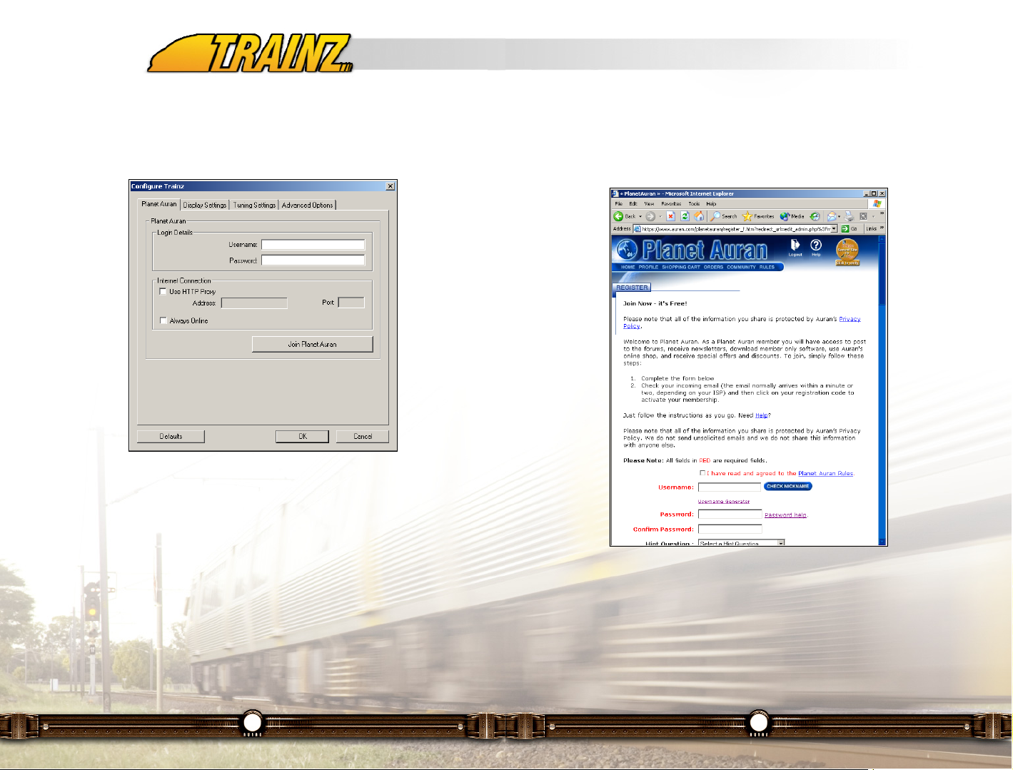
If you have not already joined, click on the "Sign up for a new account"
button to register. This will launch your default browser with the Planet Auran
registration page that will guide you through the registration process. You will
need to have an Internet access and be online to do this.
Once you’ve registered, by using Content Manager Plus you’ll have access to
over 40,000 different items such as routes, engines, rolling stock, buildings,
bridges, track, etc so that you can build exactly the rail empire you want to.
Once you have joined Planet Auran, you can enter your Username and
Password and check the "Always Online" box.
12
7 - Configure TRS2006
This is where you can customize various options to maximize your enjoyment
of Trainz Railroad Simulator 2006.
7.1 Planet Auran
Planet Auran is the rapidly growing online community that is free for all
TRS2006 users to join.
Why join? Because there is an incredible wealth of additional information and
content available that will enormously expand your enjoyment of TRS2006.
Highlights include:
• Additional files and utilities that help you get the most out of
TRS2006;
• Online forums (message boards) where you can ask questions
you have about using TRS2006 and learn from others; and
• Interactive online features like iTrainz Chat and iPortal.
Page 8
15
scene, it is possible to make the latest hardware struggle. Quite simply, the
better your hardware, the better the performance.
To balance scene density and frame rate, your challenge is to decide whether
to decrease the sliders, thereby lowering the quality or upgrade your hardware
to improve performance.
Note: These settings are also accessible in the Driver and Surveyor
modules under the main menu. See sections 9.14 and 11.13.8 for
further details.
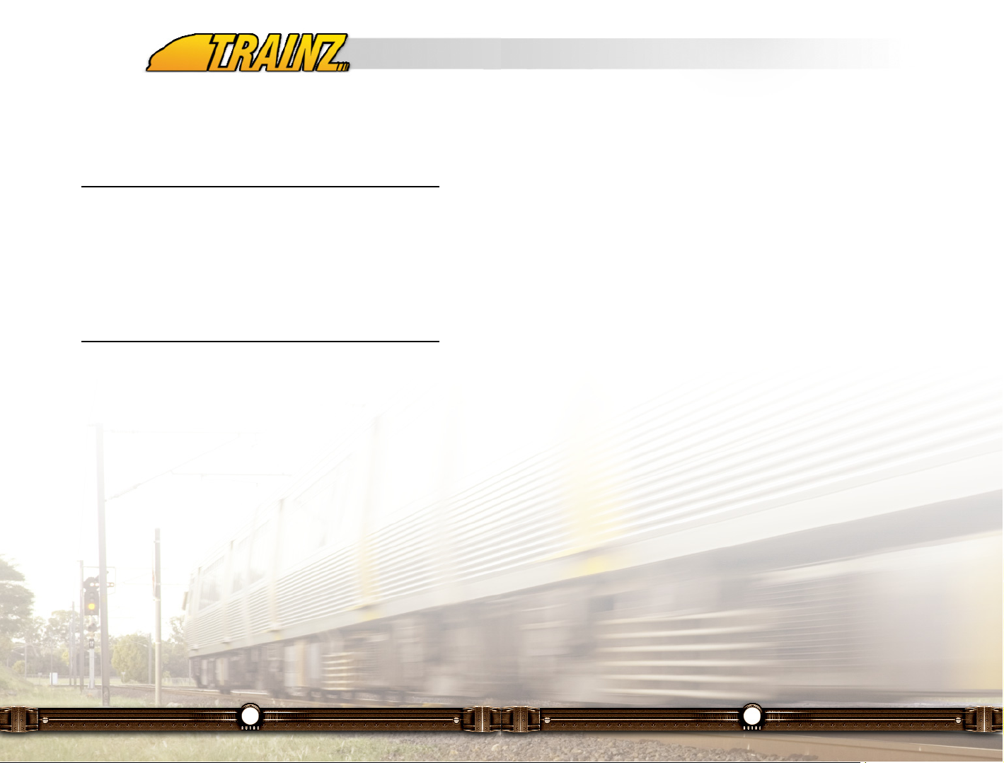
Ground - Texture Passes
Determines the number of ground textures per area. Set Texture Passes to the
first notch (0) and you will see square textures. Moving the setting to '1' and
you will notice one set of textures blend into the next one. Some graphics
cards handle multiple textures better than others.
14
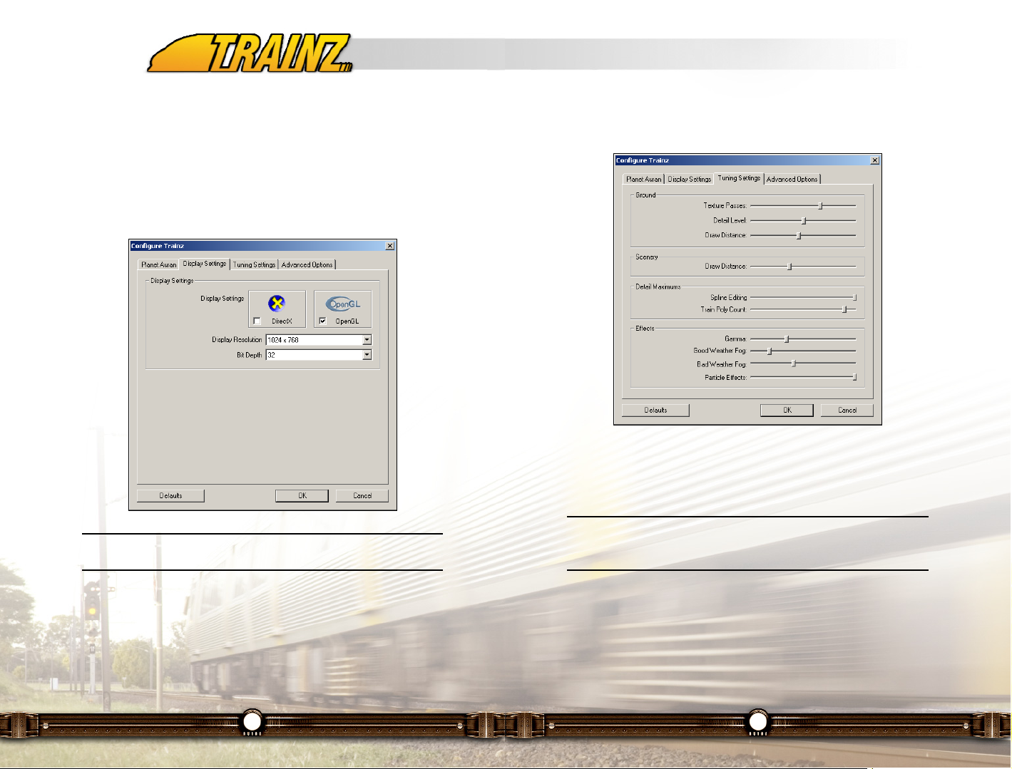
7.2 Display Settings
Next, click on the Display Settings menu tab. DirectX mode or OpenGL mode
can be used depending on your graphics hardware requirements. For older
systems, DirectX generally improves rendering speed. Experiment to see
which graphics setting works best with your hardware. Display Resolution
determines what resolution your screen will run at. Bit Depth should be left at
32 bit unless your graphics card doesn’t support 32 bit graphics.
Note: Ensure that your latest graphics drivers are installed for
maximum performance.
7.3 Tuning Settings
This is where you can configure TRS2006 to create a balance between your
hardware and your graphical performance and frame rate. Each of the sliders
affects the way the graphics are handled in Trainz and only the latest systems
will allow you to run with "full sliders" (moved to the right) and maintain
satisfactory frame rates. Even then, by adding more objects or trains to a
Page 9

17
Effects - Bad Weather Fog
Works in the same manner, but is only drawn when it is raining or snowing.
Effects - Particle Effects
Level of effects such as smoke from a locomotive or factory chimney. The
lower the setting, the less smoke etc. you will see, but your graphics
performance will increase.
7.4 Advanced Options
These options let you tweak some of the other hardware related systems to
improve performance even more. The main bottleneck on current graphics
cards is the Shadows option. Turning this option off will generally improve your
performance dramatically. For a full explanation of the other options, please
read the Readme found on the Trainz Launcher.
16
Ground - Detail Level
Defines the degree of definition in the terrain. The lower the settings, the lower
the number of ground polygons drawn.
Ground - Draw Distance
Defines the maximum viewable distance of the ground. A higher setting will
stop the ground "popping" into view, but requires a more powerful video card.
Scenery - Draw Distance
Determines the maximum viewable distance of the scenery objects. Generally
you should set this at a similar scale to the ground draw distance.
Detail Maximums - Trains Poly Count
Determines how many polygons will be allocated to the locos and wagons on
screen. The number of cars displayed at one time also affects this rate, so a
low setting with lots of cars will result in some deformation of the models.
Detail Maximums - Spline Editing
Can be set at 3 levels. At the simple setting, the splines are drawn in "white
line" form until you have finished laying the last spline point. At the detailed
level, the splines are updated dynamically as you are laying them.
Effects - Gamma
Sets the brightness of the screen while in TRS2006. If you are finding the
screen too dark move the Gamma slider to the right, if it's too bright move the
Gamma slider to the left.
Effects - Good Weather Fog
Adjusts the distance the "fog" is drawn. The lower the setting, the less fog is
drawn. Fog itself, however, doesn't place a high load on your system. Rather,
it is used to disguise the visual artifacts that can occur in the distance if your
sliders are set low. Therefore, it is recommended that if you have your general
performance sliders set low, you should increase the fog slider to hide the
visual "clipping".
Page 10
19
-disablestencil
Overrides the StencilBits selection and forces it to zero.
-ColorBits=XXX
Selects the number of bits used for the color buffer. Usually 16, 24, or 32.
Larger numbers result in better color accuracy and less dithering. Some cards
may require ColorBits = (DepthBits + StencilBits)
-Jet=XXX
Provide the path to the Jet folder. In the release version of Trainz, this is the
path from the Trainz directory to the bin directory, ie. "bin". For internal builds,
this usually points at the "Jet" directory, not "Jet/Bin". This option is required,
if it is set incorrectly Trainz will crash at load time.
-ResourceMemory=XXX
Specifies the amount of memory reserved (in megabytes) for resource disk
caching. This will prevent Trainz from accessing the disk as often, reducing
caching time and 'stutter' caused by slow disk access. This option defaults to
0.
-vsync
Activates 'vertical sync'. This option may be overridden by the video card
driver settings. When active, vertical sync results in smoother updates (no
visual tearing) but lower frame rates. This is usually a good thing. This is
equivalent to "-vsync = 1".
-vsync=XXX
See "-vsync" for more info. Allows finer control over vsync, attempting to synch
to every second frame ("-vsync=2") or every third frame ("-vsync=3") etc.
Larger numbers lower the maximum possible frame rate further but may
improve the chance of achieving a steady frame rate. Probably not useful for
most people.
18
7.5 Configuration File Settings
You can also tweak performance of TRS2006 to suit your PC hardware by
using a text editor like Notepad to edit the "trainzoptions.txt" file. You will find
the "trainzoptions.txt" file in the directory into which you've installed TRS2006.
WARNING: Please be aware that these command line parameters
are to be used at your risk. If you experience any problems with
your copy of TRS2006, including crashing or visual problems,
return your "trainzoptions.txt" to its original state (see Section
9.4) before contacting the Auran helpdesk. Auran will not be able
to provide support on issues that relate to the use of these
options. Before you start playing with the "trainzoptions.txt" file
why not make a backup of the default "trainzoptions.txt" file by
saving the file with a different filename, say "trainzoptions.BAK".
7.5.1 Command Line Parameters
-DepthBits = XXX
Select the number of bits used for the z-buffer (depth buffer.) Available choices
are generally 16, 24, or 32. Some video card drivers incorrectly interpret '32'
as '16', so '24' may give better results on these cards. When a stencil buffer is
used, the depth bits may need to be adjusted down according to the size of
StencilBits; ie. 24 depth + 8 stencil = 32 total. It is possible that this option can
be overridden by the settings for the video card driver.
-StencilBits=XXX
Selects the number of bits used for the stencil buffer. Usually 0, or 8. A stencil
buffer is required for Trainz to render shadows. Some cards do not support
stencil buffers, or do not support stencil buffers in certain resolutions / modes.
Where a card does not support a Stencil Buffer, the driver will sometimes
attempt to use a Software stencil buffer, which is very slow. Generally a 24 or
32 bit DepthBits is required in order to enable the Stencil Buffer.
Page 11

21
graphics cards. Larger numbers will improve the z-buffer accuracy and may
provide less artefacts, especially in 16-bit depth buffer modes, however there
may be problems viewing nearby objects such as inside cabin view.
-zfar=XXX
Override the default z-buffer far distance. Specified in meters. The default is
1500m. Decreasing the far distance will result in slightly improved z-buffer
accuracy but will result in far-away objects not being visible (Note: this may not
result in a speed gain if a high draw distance is specified in the Trainz tuning
screens as Trainz will still consider the far-away objects as visible even if the
video card is unable to render them.) Increasing the z-buffer distance probably
isn't useful as Trainz doesn't allow the selection of draw distances greater than
about 1300m, and the z-buffer accuracy will be decreased causing visual
artefacts.
-disablefog
Causes fog to be completely disabled.
-fullscreen
Causes Trainz to take over the chosen display. This is the preferred mode.
-windowed
Causes Trainz to run in a window. This is useful for debugging, however may
result in reduced frame rate and cause visual 'stutters', especially in DirectX
mode.
-dualhead
Enables support for dual-display mode. This will only work if you have two
displays attached to a single video card acting as a single, large display (i.e.
single frame-buffer). This wont work if there are two displays on different video
cards or configured to act as independent displays. Currently dualhead
support is only utilized in the Driver module. This option requires that a
dualhead resolution is selected (ie. 8:3 ratio) and that Trainz is run in fullscreen
mode. On some video cards this option may require you to switch to the
appropriate resolution prior to launching Trainz.
20
-frequency=XXX
Attempt to force the refresh rate of the display to the specified frequency (in
Hz.) If the video card does not support the specified frequency at the specified
resolution, this may cause Trainz to exit on load with a "check your settings"
message. Some common frequencies are: 60, 70, 72, 75, 85. Higher numbers
provide visually better results as long as the display properly supports the
requested frequency. Selecting a frequency which is supported by the video
card but too high for the display is untested and could cause the display to
become garbled.
-width=XXX
Manually specify the window/screen width (in pixels). When in fullscreen
mode, this must match one of the available display resolutions, and an
appropriate height must be selected. When in dualhead or surround modes
this is the horizontal resolution across all displays, not across a single display.
-height=XXX
Manually specify the window/screen height (in pixels). When in fullscreen
mode, this must match the Width setting used. Width-to-Height ratios other
than 4:3 are untested. When in dualhead or surround modes, this is still the
vertical height of a single display.
-640
Equivalent to specifying "-width=640" and "-height=480".
-800
Equivalent to specifying "-width=800" and "-height=600".
-1024
Equivalent to specifying "-width=1024" and "-height=768".
-znear=XXX
Override the default z-buffer near distance. Specified in meters. The default is
0.1 meters. Smaller numbers allow the viewing of objects closer than 10cm but
rapidly decrease the z-buffer accuracy and will cause visual artifacts on most
Page 12

23
-intro=XXX
Changes the playing mode of the Trainz loading movies. Available options are
"disable" and "fullscreen". Fullscreen causes the movies to be played in
fullscreen mode instead of centered on the screen. Disable skips the intro
movies.
-quit
Causes Trainz to quit after the loading sequence has completed. Used for
diagnostic purposes only.
-DisableEnvMap
Causes Trainz to not render Environmental maps. This may improve
performance on certain minimum-spec (or lower) graphics cards.
-framerate=XXX
Requests that Trainz limit the frame rate to the specified number of fps. Not
tested. Doesn't appear to work with vsync enabled. May help with maintaining
a stable frame rate on faster machines.
-render=renderdirectx
Cause Trainz to use the Direct3D API for graphics rendering as opposed to
OpenGL (default). This may improve performance or compatibility where the
video card drivers do not correctly support OpenGL.
-autopilotsignaldistance = XXX
Modifies the autopilot signal-visibility distance, specified in meters. Default
value is 200m. Smaller values are not permitted. This will affect how the
autopilot reacts to the signals - how soon it will begin to slow down and how
close to the signal it will attempt to stop.
-disableztest
Turns off z-buffer testing for coronas (signal flares, headlights, sun.) This will
make the flares shine *through* other objects, however will reduce artefacts
with the ground and train clipping the flare.
22
-surround
Enables support for triple-display (triple-head / surround gaming) mode. This
will only work if you have three displays attached to a single video card acting
as a single, large display (ie. single frame-buffer.) This wont work if there are
three displays on different video cards or configured to act as independent
displays. Currently surround gaming support is only utilised in the Driver
module. This option requires that a surround gaming resolution is selected (ie.
12:3 ratio) and that Trainz is run in fullscreen mode. On some video cards this
option may require you to switch to the appropriate resolution prior to
launching Trainz.
-disablecarz=X
Default 0 (carz enabled). If set to 1 (carz disabled), then carz will not appear
on roads. This may (untested) result in smoother framerates. Experimental
only.
-framestoaverage=XXX
This option controls the 'smoothing' of frame rate timing. Increasing this option
may result in less visual 'stutter', however can cause period 'surges' if rapid
changes in frame rate occur. Increasing this option may be useful for high-end
machines with fast graphics cards where the frame rate remains fairly
constant. Default is 4, maximum is currently 16, minimum is 1 (no averaging.)
-heartbeat=XXX
Specify the time interval at which the physics heartbeat occurs (in seconds).
Defaults to 0.03sec. Larger intervals decrease processor usage for physics at
the expense of accuracy. Intervals larger than 0.05sec are not recommended.
Changing this option is probably unnecessary and may have a negative
impact on physics accuracy.
-filter=XXX
Specify the texture filtering mode. Default is trilinear which provides the best
visual results. Other options are bilinear and none. This option is unlikely to
provide performance gains, except perhaps on minimum-spec (or lower)
graphics cards.
Page 13
25
7.6 Troubleshooting
If you get any error messages or have problems while running Trainz, please
read the Readme found on the Trainz Launcher for general information on how
to solve these issues. Make sure that you have the latest video card drivers
installed and that you have installed DirectX 9 or above.
You can also visit the website and go to the Technical Support section for the
latest fixes and solutions. Another excellent source of information is the Trainz
forums where users just like you offer tips and tricks for almost any aspect of
using Trainz or getting the most out of your experience.
24
-showcachebar
This option enables the display of the cache bar. The cache bar is the
horizontal red bar that appears in the bottom left corner of the screen when
assets are being loaded such as when you open a route up or a moving
around in a large route. Unlike previous versions of Trainz, TRS2006 does not
have the cache bar displayed by default.
-debug
Including this option enables debug mode. The main feature of debug mode is
that it allows you to accelerate the game speed by holding down the Shift key.
This can be useful for content creators that might want to test their sessions
more quickly. However debug mode is not a supported feature and the
behavior of Trainz in not guaranteed when using the Shift speed-up.
-allownoctrlrightclick
Disables the requirement of having to hold the Ctrl key when using RMB top
open the menu of a vehicle or industry in Driver. Previous versions of Trainz
did not require the Ctrl key to use RMB to access the menu and this option
allows for those who prefer the older way.
7.5.2 Defaults
If you have been tweaking the "trainzoptions.txt" file and caused your
TRS2006 install to become unstable you can either copy in the backup file we
asked you to create in Section 9.2 or you can return it to the default
"trainzoptions.txt" file by making it read as follows:
-DepthBits=24
-StencilBits=8
-fullscreen
-Jet=bin
-cabinfov=65
-driverfov=55
-DefaultAutoMip=none
Page 14

27
9 - Driver
9.1 Introduction
The Driver Module provides a lot more than just a train driving simulation.
TRS2006 provides you with a number of different ways of controlling the trains
on your railroad.
Firstly you can hop into the cab and explore the tracks from behind the throttle.
You can choose either the simple DCC speed control system or the realistic
Cab controls using each of the levers and switches in the cab. You can watch
the trains from trackside as they come thundering past, or from a bird’s eye
view tracking along with the train.
You can even switch to a Map View and control all the junctions, monitor
signals and control traffic flows from a 2D perspective.
While running multiple consists, you can choose to control each train yourself,
or let the computer AI system control the trains as you control the switches.
Finally, you can even issue specific orders to Drivers that you allocate to each
train.
In addition to the various systems of control, there is also a fully interactive
industry model that automatically generates waybills for goods that need to be
delivered to the various industrial sites. Your task under this mode is to
maintain the operation of these industries by controlling movement of goods
and resources along your railroad. You can watch as your train or the trains
under the control of your drivers are each loaded and unloaded at the various
industries. For more information about configuring an industry, see section
10.4.4 of this manual.
Note: This chapter is only an introduction to Driver. More detailed
instructions can be found in Chapter 12 - Engineer’s Guide.
26
8 - Launching TRS2006
Use your mouse to highlight the menu options in the Trainz Launcher then use
the LMB on the "Launch Trainz" menu option and you will see the loading gear
rotating whilst Trainz takes a few moments to load.
In the Trainz Main Menu, there are 3 game modules to choose from: Surveyor,
Driver and Railyard, as well as the Trainz Exchange option.
The following sections of this TRS2006 Manual give you a basic
understanding into each of these areas.
Note: To find out more about the Driver module, read Chapter 9.
Surveyor is covered in Chapters 10 and 11.
Page 15
29
When you click on a Session, check the text information contained in the
Description window that appears in the top left of the screen. Note how the
"Load” button appears at the bottom right of the screen when a session has
been selected.
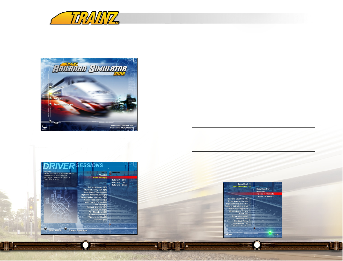
9.2.1 Tutorial Sessions
TRS2006 includes 6 introductory tutorial sessions to help you get started with
using Driver. The 6 tutorials listed in order are:
• Tutorial 1 - Controls (British Midlands 2)
• Tutorial 2 - Waybills (British Midlands 2)
• Tutorial 3 - Diesel Cab (City and Country USA 2)
• Tutorial 4 - Steam (Outback Australia 2)
• Tutorial 5 - Drivers (Highland Valley Industries)
• Tutorial 6 - Commodities (City and Country USA 2)
Note: The tutorial sessions take place on several different routes and
won’t appear in order on the Driver Main Menu. To get to a tutorial, find
its corresponding route in the above list and expand that route in the
Driver Main Menu.
To get started Click LMB on the "British Midlands 2" route. Then select
"Tutorial 1 - Controls". Once the session has been selected, Click LMB on the
load button found in the bottom right corner of the screen.
28
9.2 Starting your Railroad Career
Once you have launched TRS2006, start Driver by Clicking LMB on the Driver
menu option.
Once Driver loads you will see a list of available Routes with the number of
sessions available for each route shown in the brackets next to it. Click on a
route, then select a session.
Page 16
31
that the selected car now becomes the focus of the view. You can also press
the "-" and "+" keys on the main keyboard to select the next or previous car in
the consist. You can even Click LMB on other trains to shift the focus to the
selected train or click on the consist icons in the 2D Map View as well.
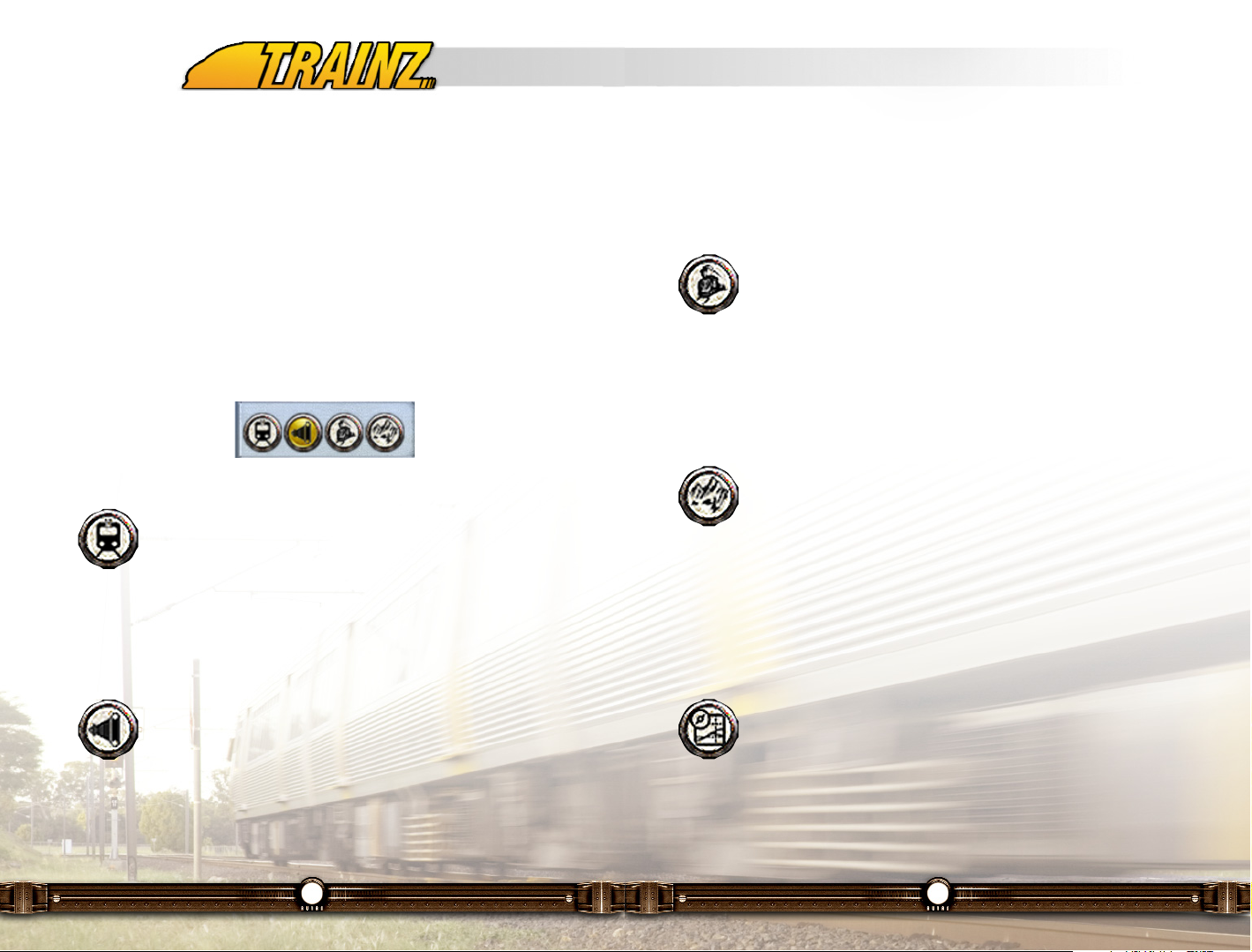
9.3.3 Tracking Views
Now Click LMB on the Tracking View icon and your view changes
to the nearest Tracking camera. There are two types of cameras;
Static and Tracking, and these are placed in the 3D world in
Surveyor mode. Static cameras will stay fixed in direction and allow the
tracked object to move out of the frame. Tracking cameras are fixed in place,
but pan with the tracked object, keeping it in the center of the view. If there are
no Tracking/Fixed Cameras within visual range of the tracked object, the view
reverts back to the external view until a Tracking Camera comes within range.
9.3.4 Free Roaming View
The Free Roaming view is extremely flexible and operates in a
similar fashion to navigating in Surveyor. To move the camera focus
point, simply Click RMB in the 3D world to where you want the new
central focus point to be. The view smoothly moves to the new focus point.
Now you can use the cursor keys to rotate or change elevation and the mouse
wheel or Page Up/Page Down keys allow you zoom in and out. By holding
down RMB and moving the mouse you can continuously change the focus
point and hence the view. By combining this mouse movement with the cursor
keys and the zoom function it lets you roam around the scenery at your will.
9.3.5 Map View
The icon for the Map View is at the bottom right of the screen or you
can use the Ctrl-M shortcut key. You will find the Map View is useful
to get an overview of where your trains are in relation to the
industries, the track configuration, plotting your train movements, and
checking turnout settings and signal states.
On the 2D Map View you will see the position, length and name of each
Consist, the direction set for each turnout and important names for assets
30
Trainz will now start running Tutorial 1 where you will be guided through all the
basic controls that make up the TRS2006 Driver interface. Once you have
gone through Tutorial 1, go through the other tutorials and see what else there
is to do.
9.3 Camera Controls – Controlling Your View
There are many different views of the 3D world in TRS2006 as well as a Map
View that gives you a 2D top down view. You can zoom in or out, pan around
and change the camera focus point with each of these views.
Shown here is the Camera HUD Panel. The different camera view icons and
their shortcut keys are listed as follows. Try to explore the Trainz world with
them.
9.3.1 Cab View
Firstly, make sure the view is focused on a locomotive (Click LMB
on a loco to focus the view) then Click LMB on the Cab View button
(or use the "1" key). Your view is now from in the driver’s seat of the
cab. Use RMB+H to look around the cab and out of the different windows. You
can also change your viewpoint in the cab by pressing the "[" and "]" keys. If
the locomotive is a dual cab unit you can press the "Alt+C" key to switch
between the cabs.
9.3.2 External View
When you first start Driver you will generally be in the External View
with the scene focused on a particular locomotive. Use RMB+H and
move the mouse around to rotate and elevate the view (you can
also use the cursor keys), with the locomotive at the center of the screen at all
times. Want to get closer? You can use your mouse wheel to zoom in and out,
or use the Page Up/Page Down keys on your keyboard.
If you Click LMB on one of the cars attached to the train, the view changes so
Page 17
3332
such as turnouts, industries and stations. Zoom in and out using the "Page Up"
or "Page Down" keys (or your mouse-wheel) to see more or less of the route.
The map follows the movement of the currently selected Consist. The currently
selected Consist shows as green and all other Consists show as gray on the
map. Click LMB on one of the gray Consists to center the map view on that
Consist.
Click RMB on a point in the map to center the map view to a new location,
losing focus on any particular Consist.
You can also set the turnouts by clicking on them and seeing the direction
arrows change. Also visible are the state of any signals on the Route.
Exit the map screen by Clicking LMB again on the Map Screen button, or
press Ctrl-M.
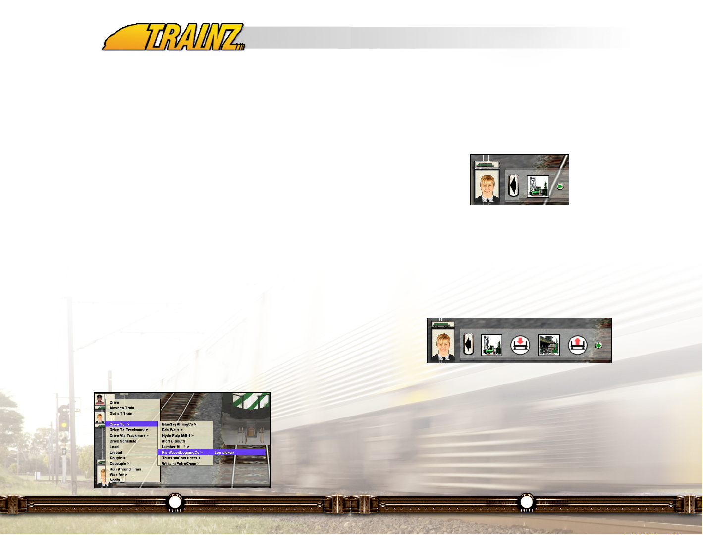
9.4 Driver Commands – Who Goes Where
Open the "FreeformiPortal" session on the "Tidewater North" route. Click LMB
on the Driver picture in the lower left of the screen and a list of allocated
Drivers appear along the left side of the screen. Click LMB on the Driver "Ami"
who should be at the bottom of the list. The camera focuses on the loco of the
selected Driver.
We will get this driver to pick up the logs from the Logging Co. and take it to
the Lumber Mill.
Click RMB on the driver's picture to bring up the Driver Command menu.
Select Drive To > RichWood Logging Co. > Log pickup from the
subsequent pop out menus. Note that an icon representing the logging yard
appears at the bottom of the screen next to the driver picture. The Driver will
immediately begin to carry out his duties, and you can queue up additional
orders whilst he is driving.
Click RMB on the driver’s picture and select Load from the Driver Command
menu. The Load icon appears to the right of the logging yard icon. Continue
on with the sequence and selecting Drive To > Lumber Mill 1 > Logs Drop
off and then the Unload command.
You should now have a group of four “Command” icons across the bottom of
the screen that represent the commands you have given to this Driver.
Your Driver will continue with his duties in the order that they appear along the
bottom of the screen, taking into account speed restrictions and other rail
traffic. Each time a task is completed, the Command icon disappears and the
Driver commences his next task.
Not only can you issue orders to several Drivers at once (up to 7), you can also
give Drivers orders to accomplish tasks based on the Waybill list of industry
requirements at the same time. Once your orders are allocated, watch as your
railroad comes to life around you.
Page 18
35
9.6 Driving in Diesel/Electric Cab Mode – Are you ready?
Cab Mode provides a more realistic driving experience taking into account
factors such as the different power levels at each throttle notch, or the length
of the train when applying the brakes. Each of the levers, switches and dials
in the 3D cab can be used to operate the locos or you can use the Hotkeys or
Cab Control HUD to carry out the same function. (This lets you control the
locos from outside, even in Cab Mode).
The following tips will get you started, but we recommend that you check out
Chapter 12 - Engineer’s Guide of this manual more detailed information about
driving using Cab controls.
Launch Driver and select "Tutorial 3 - Diesel Cab" from the expanded list of
the "City and Country USA 2" route. Click LMB on the "Load" button at the
bottom right of the screen to launch the Driver Session. Follow through the
tutorial’s instructions to learn how to drive a locomotive in cab mode.
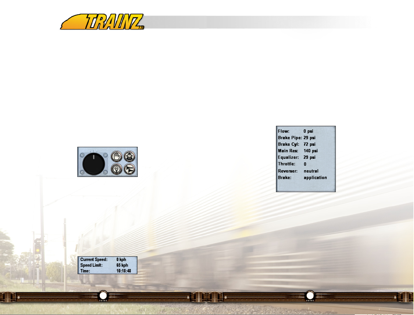
To start a locomotive in cabin mode, release the train brakes ("Q"). If the brake
cylinder has not emptied you may need to also release the independent brake
("D"). Put the reverser into forward pressing "F". Increase the throttle ("W")
slowly and the train will begin to move forward. Use "X" to decrease the throttle
and "S" to set the throttle to idle. Use "A" to apply the brakes, and "Z" to lap
the brakes. Watch the information in the Cabin HUD Panel to get information
on speed, throttle, brake settings and Reverser direction.
34
When you need to exit, move the mouse to the top left of the screen, a menu
scrolls down and you Click LMB on the Exit button (X) or hit the Esc key. A
pop-up window asks if you want to save this session – very handy if the real
world interrupts your Railroad Operations.
9.5 Drive that Train – You Take Control
There are times when you will want to get into the cab of your very own
locomotive and take charge. When any one of your Drivers has no current
commands, the Driver HUD appears on the right hand side of the screen. If
you are in DCC mode, you will see a speed dial. This is a simplified control
system not unlike the DCC (Digital Command Control) systems used on model
railroads. Using the dial you can control the speed of your loco and get a feel
for driving without having to worry about monitoring brake pressures or
knowing which lever to pull and when.
Click LMB+H on the speed dial and drag to change speed. Click LMB on the
Stop icon to stop the train. There are momentum effects built into this control
system, so don’t expect the train to stop and start immediately. Alternatively
use the "W" and "X" keys to accelerate and decelerate respectively. Use the
"S" key to get to idle state and the "A" key to apply the handbrake.
The current speed and the track speed limits are shown at the top right of the
screen in the Time and Display HUD Panel. Make sure you obey all signals
and speed restrictions along the way.
Page 19
37
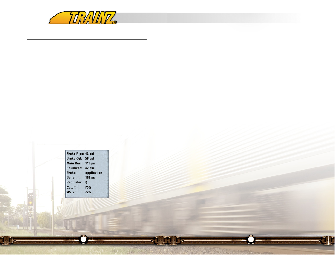
gauges; they should show be half to two-thirds in the glass. Water level in the
boiler is increased by use of the injectors.
Once full pressure has been attained and the brakes released ("Q" and "D"),
you can move the locomotive by opening the regulator. The "cutoff" is the
percentage of the piston's travel that steam is applied to it and is affected by
use of the reversing gear. Full stroke length is 75% and is used for starting the
train. As the train begins to gather momentum, the cutoff is reduced and the
expansive qualities of steam are used to generate power without depleting
boiler pressure so rapidly. As the cutoff is reduced, there is increased potential
maximum speed and reduced cylinder power output.
Long cutoff (40-75%) delivers higher tractive effort and increased coal/water
consumption. Short cutoff results in lesser tractive effort, but more efficient fuel
consumption. Operating at high speeds in full forward gear will soon deplete
the boiler. A parallel can be drawn with an automobile, where fifth gear is great
on fuel, but not so efficient when you come to a hill. The cutoff is a very
important tool in managing the available steam.
When nominal boiler pressure is exceeded, Safety Valves lift to vent excess
pressure to the atmosphere. A good crew will avoid this waste of steam and
fuel by striking a good balance between the temperature of the fire, the
pressure in the boiler, and the conditions of the road ahead. When
approaching a heavy ascent for example, a hot fire will be required to maintain
adequate steam pressure. Conversely when approaching an easy section with
a very hot fire, pressure can be eased to prevent lifting safety valves by adding
more water to the boiler.
Observe the water level in the locomotives tender periodically, especially after
working the locomotive hard, as it may require a visit to a steam filling station
several times en route.
See Chapter 12 - Engineer’s Guide of this manual for more detailed
information about driving a locomotive in cabin mode.
36
Note: You cannot engage the Reverser unless the throttle is at idle.
See Chapter 12 - Engineer’s Guide of this manual for more detailed
information about driving a locomotive in cabin mode.
9.7 Driving a Steam Engine – Are you up to the challenge?
Entering the cab of a steam locomotive for the first time during a new session,
you will find that the light-up crew will have prepared you a nice hot fire. Fire
temperature can be gauged by looking at the color; an orange fire is relatively
cool, and a white-hot fire is required to raise the necessary pressure to power
the locomotive. You should have a nice head of steam already raised and you
can check the gauge pressure either in the cab or on the Cabin HUD Panel
(pictured below).
Launch Driver and select "Tutorial 4 - Steam" from the expanded list of the
"Outback Australia 1" route. Click LMB on the "Load" button at the bottom right
of the screen to launch the Driver Session. Follow through the tutorial’s
instructions to learn the basics of a driving a steam locomotive in cabin mode.
Opening the firebox doors to increase the airflow and add more coal to the fire
by pressing the spacebar. The doors MUST be open to shovel coal. Care
should be taken not to add excessive coal, as this will lower the temperature
of the fire for a time. As the fire heats up, the boiler pressure should start to
rise. Always ensure there is sufficient water in the boiler by checking the water
Page 20

39
2. A part of a train may be occupying a part of the block it protects,
the signal shows red preventing any further traffic from entering
the block; or
3. A part of a train may be occupying a part of the adjacent block
when the signal will display Caution to indicate that the next
signal is at stop.
When a train encounters a green light, it is permissible to pass the signal at
normal speed. The signal will stay green until the rear of the train enters the
block, at which time it will change to red. Once the train leaves the block, i.e.
passes the next signal, the first signal will turn yellow, meaning it is safe to
proceed as far as the next signal which is now at stop.
When a light is at Yellow, the Driver must proceed at half speed and of course
you must always stop at a Red signal unless the Controller allows you to pass.
During Driver sessions, any of the circumstances that result in a red or yellow
signal can be revealed. Move the mouse pointer over the signal lamp, and a
message will display the status of the block. Clicking on the signal lamp will
transport you to the obstacle whether it is a turnout that needs switching, a
terminating line or another train. Alternatively, your path can be cleared using
the 2D Map Screen overview.
Tip: If your AI Drivers seem to be misbehaving, you may have placed
your signals incorrectly. Read the Signaling Guide for more
information on how to place signals correctly.
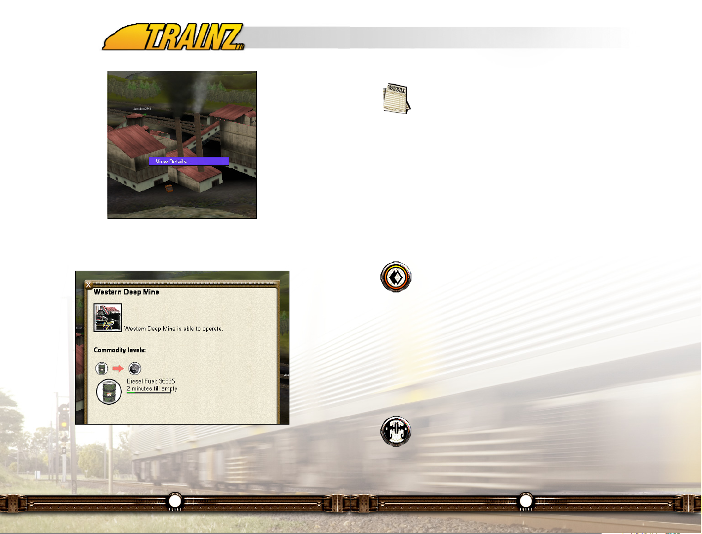
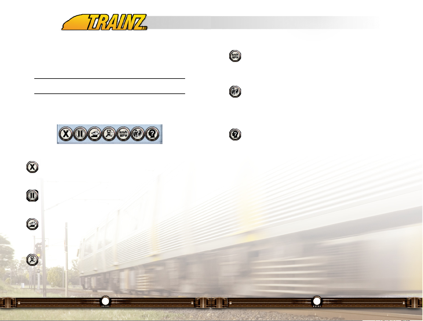
9.10 Industry Information
Behind each interactive industry in TRS2006 is a complete resource model
where industries consume resources and produce goods. Click Ctrl+RMB on
an interactive industry and a pop up menu will appear. You can Click LMB on
View Details to open up a pop up window that describes the industry and the
current Commodity levels.
38
9.8 Operating Turnouts
You change the direction of the Turnout (Junction/Switch) by Clicking LMB on
arrows associated with the Switch. The green arrow points in the direction the
Turnout is set to. If you are in the Cab, hold the Ctrl key when you Click LMB
or use the J key to change the junction ahead (Ctrl-J if you are reversing).
You can also change turnouts in the 2D Map View, which is useful for planning
your train’s movements well in advance of its progress.
Tip: Click between the arrows to change their direction.
9.9 Signals
TRS2006 primarily uses a basic block signal approach but there is a large
amount of flexibility built in to allow customized signaling systems that
reproduce many of the different types of signaling found around the world.
The most typical light signal states are shown below. For a more complete
discussion of signaling (including semaphores) see the Signaling Guide.
Indications are as follows:
Green - Line Clear
The next signal is either green or yellow, proceed at normal speed.
Yellow - Caution
The next signal is red, proceed at low (half) speed.
Red - Stop
The block is occupied, terminates, or is closed.
All of the signals are red unless a train is approaching one, in which case it will
turn green to allow passage of the train. There are several reasons why a
signal may not be showing green in the presence of a train:
1. The line may terminate or be closed, meaning a turnout within
the block it protects is set against it;
Page 21
41
9.11 Waybills – Who Needs What
Click LMB on the Waybill icon to bring up a list of industries that have
created waybills showing that they require certain products for
delivery. Click LMB on each industry icon in the list to show what
quantities of products are required.
Waybills are automatically produced by an industry when that industry reaches
a percentage of capacity of a particular commodity. Once the full amount
required by the Waybill has been delivered, the Waybill is deleted from your
list (although another one may well have appeared in its place).
The tutorial sessions "Tutorial 2 - Waybills" (British Midlands route) and
"Tutorial 5 - Drivers" (Highland Valley Industries route) introduce you to how
Waybills can be used to keep you informed.
9.12 Commodities
You can allocate which commodities are carried by a particular item
of rolling stock. Click on the Commodities icon on the lower right of
the screen to bring up the Commodities Menu. Click on an
appropriate icon and then click on an item of rolling stock. The icon shows that
the rolling stock is now limited to carrying only that type of Commodity. To stop
any commodity being loaded or unloaded, use the "Stop" icon. To allow the
default load only, use the "Default" icon. You can only assign commodities to
vehicles built for carrying that type of commodity.
Play through "Tutorial 6 - Commodities" on the "City and Country USA" route
for an introduction to working with commodities.
9.13 Decoupling
To activate decouple mode, click on the Decouple icon (or press the
"Ctrl-D" key), then move your cursor over the couplers between train
cars until you see a red decouple icon. When the red decouple icon
appears, click LMB to decouple the consist at this point. When you have
successfully performed the decouple operation, the red coupler icon “opens”
and a message is displayed on the screen. The act of decoupling creates a
40
See the section 10.4.4 of this manual for more detailed information on how to
configure commodity levels in an industry.
Close the window by Clicking LMB on the "X" in the top left corner.
Page 22
43
Imperial/Metric (G)
Toggles the settings from Imperial to Metric or vice versa. This will affect
parts of Trainz that involve the display of measurement/speed
information such as the Time & Speed HUD Panel.
Find (Ctrl-F)
Lets you locate a particular item such as a junction, station, loco or
interactive industry. Selecting the item will move the camera position to
that position on the route. See section 11.13.4 for further details of the Find
functionality.
On Screen Help (Ctrl-H)
Toggles the display of on screen icons such as turnout direction
markers.
More details of what these icons do can be found in section 12.6 of this
manual.
9.15 Mastering Operations
The tutorials mentioned in section 9.2.1 show you how simple it is to get
started in Driver mode to operate the railroads that come with TRS2006 or
those built by yourself or others. For an expanded explanation of the
capabilities of Driver Mode, see Chapter 12 - Engineer’s Guide of this manual.
42
new consist and your camera remains focused on the same car or loco as
before the decoupling operation. To re-couple, ensure that you are operating
at speeds below 5mph (8kph). Experiment with different camera positions to
make this task easier.
Tip: In DCC mode you must apply the handbrake ("A") before
uncoupling to avoid runaway wagons.
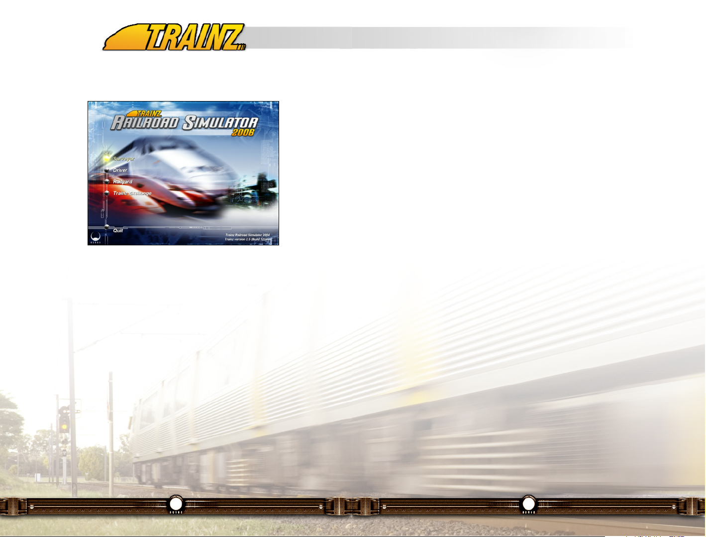
9.14 Other Functions
At the top left, there is a group of icons that let you carry out other general
functions.
Exit (Esc)
Quit the current session back to the Driver Main Menu or Surveyor
screen with the option to save the session before exiting.
Pause (P)
Suspend the current session so that you can answer that important
phone call or finally stop for a lunch or dinner break.
Save (Ctrl-S)
Lets you Save your progress including where each train is located and
the state of each industry. To reload a Saved Session, choose the
"Saved Session" option from the Driver Main Menu screen.
Performance Settings (Ctrl-T)
This is where you can tweak the graphics slider settings to improve the
visual quality of your game. See section 7.3 for more details of what
these settings do.
Page 23
10 - Surveyor
10.1 Introduction
Welcome to Surveyor, the user-friendly World/Route/Layout builder. Surveyor
is a tool where you can jump in straight away and have some fun, but also may
take some time and patience to master.
Using Surveyor and your imagination you can create terrain, paint it with
textures and then populate it with trees, shrubs, buildings, roads, power lines,
animals and people. You can create lakes and rivers, change the weather
conditions and even change the color of the sunset.
There is the ability to create your railroad, with track, stations, signals,
maintenance facilities, turntables and the plethora of trackside infrastructure
that combine together to form a working railroad. You can edit the default
Routes or start out from scratch making your own creation. You can also
download a huge number of Routes created by others from the Trainz
Download Station and modify them to suit your tastes.
In Surveyor you also place the locomotives, rolling stock and drivers that are
the "actors" on the stage you create for each of your Driving Sessions.
44
10.2 What’s new in Surveyor Mode in TRS2006?
If you are familiar with earlier versions of the Trainz product, we thought we'd
give you a quick list of significant differences in the Surveyor module between
TRS2006 and the earlier versions:
• Backdrop scenery items
• Animated turnouts
• More than 50 rules
• Custom content search filter
10.3 Flexibility and Framerates
Welcome to the Surveyor world builder tool. Surveyor is a tool that needs
some experimentation. It is free-form, open-ended software at its best and our
users will probably find ways to utilize it beyond anything we originally
envisioned.
With this freedom also comes a dilemma. The Surveyor tool has no
constraints on the amount and variety of objects that can be placed in your 3D
world. Therein lies the issue, the more types of objects, the slower will be the
performance of the Driver component of the software. You can minimize these
frame rate effects by keeping the variety and number of objects minimal. Their
effect on frame rate is in that order, first variety and then quantity. Keep this in
mind when putting your world together and you will have a more pleasant
driving experience.
With Surveyor you can create terrain, populate it with trees, shrubs, buildings,
roads, vehicles, aircraft, ships, power lines, animals and people. Then of
course there is the ability to create your railroad, with track, stations, signals,
maintenance facilities, turntables and the plethora of trackside infrastructure
that combine together to form a working railroad.
Let's not forget the new working industries that give your railroad purpose and
the locomotives and rolling stock that are the actors on the stage you create.
We will start with a step-by-step guide to creating a very basic operational
45
Page 24

47
d
The details of this screen will be discussed later in this document.
For the purpose of this tutorial, Click LMB on Create New. We are going to
create our route from scratch. Anew window will pop up as follows, asking you
for some map details.
46
route. This will demonstrate the main aspects of Surveyor. The sections that
follow that provide a detailed description of each of the tools available to you
within Surveyor.
Surveyor is a powerful editor that lets you create your own worlds, landscapes
and railroads. Create hills, mountains, valleys and streams, populate the world
with all types of scenery objects, and of course lay your track, signals,
turnouts, consists and even program the operation of the Route.
You can edit the default Routes or those created by others. Or you can start
out from scratch making your own creation. You can also download a huge
number of Routes created by others just like yourself from the TRS2006
Download Station and modify them to suit your tastes.
The following tutorial provides you with just the basics to help you get started
in making your first TRS2006 route.
10.4 My First Railroad
In this section we will be building a single baseboard map with a hill in the
center and a simple oval of track connecting a power station to its source of
fuel, a coal mine. If you feel you are ready you may wish to skip this section
and move to the more detailed instructions beginning with Chapter 11 Surveyor in Depth.
Begin by selecting the Surveyor option on the TRS2006 Main Menu. The
following screen appears.
Page 25
49
screen is re-centered on the compass.
Next, Click RMB+H and move your mouse slowly towards the edge of the
screen. You will notice the compass following the cursor as you move around
the terrain. Learn to control the speed of movement by moving the compass
close to or away from the center of the screen. Keep practicing these
movements until you can successfully control the direction and speed you
wish to move.
Use the arrow keys on your keyboard to rotate the camera around the
compass. The left and right arrows rotate the camera. The up and down
arrows change the elevation of the camera. Press the Page Up and Page
Down keys to zoom in and out or you can use the mouse-wheel on your
mouse if you have one.
When you zoom in close, notice how the compass has the four directions N,
S, E and W. This is helpful to stay orientated in your TRS2006 world,
positioning your railroad properly with respect to the rising and setting sun. Yes
on a clear day, the sun does rise and set in your TRS2006 World!!!
Tip: Spend some time using a combination of the mouse and
keyboard commands that control the viewing pane in Surveyor. This is
an important skill to develop and some time invested now will reward
you with effortless flitting around the map as you construct your
railroad empire.
Tip: The Undo/Redo buttons are found on the top menu panel. Use
them if you want to retrace your steps backwards and forwards
respectively.
48
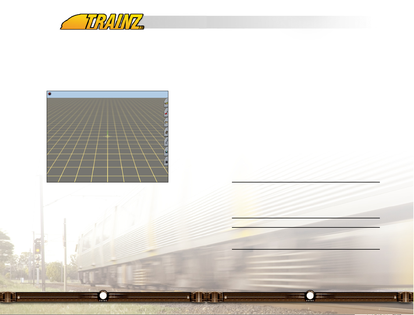
For now click in the "Route Name:" field and type "My First Layout" and leave
the rest of the fields as they are. Click LMB on the tick (checkmark) to be taken
to the Surveyor editor.
The next thing you notice is the baseboard marked out with a grid and with a
3D compass in the center of the screen.
This compass is always centered on your screen. If you get close enough to
the compass, you will see that the compass is marked with the East, West,
North and South compass directions to assist you in aligning your route
geographically.
10.4.1 Compass Movement and Camera Skills
The first task to learn in Surveyor is how to move around the baseboard and
control your camera. Mastering these two basic skills will make your time in
Surveyor much more enjoyable.
In the middle of the baseboard is your Surveyor Compass. There is also a
small white arrow on the screen. The arrow is your default cursor, which you
can control by moving your mouse. Move your cursor to the right of the
Compass and Click RMB. The compass will move to that position and the
Page 26
51
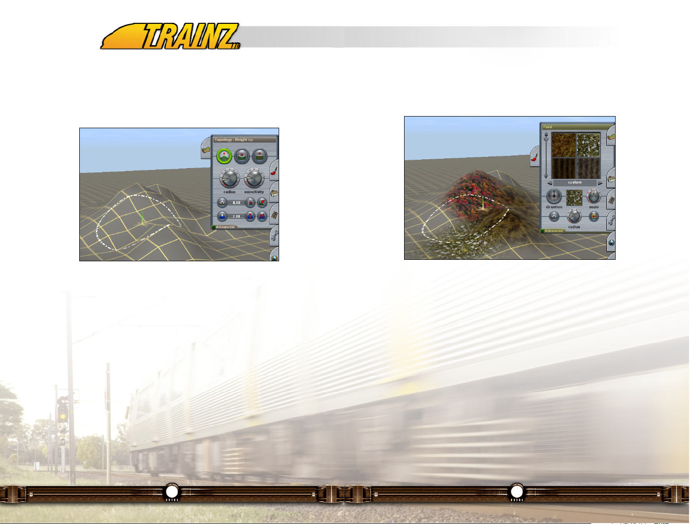
10.4.3 Ground Texturing
When you are happy with your hill Click LMB on the Painting Tab from the tabs
at the right of the screen (it's the second one down).
The Topology menu disappears to be replaced by the painting menu. Scroll
down the texture palette until you find a texture you like. Again select the
radius of the texture effect by Click LMB+H on the Radius dial and moving it
until you are happy with the size of the painting circle. Then Click LMB to apply
the texture to the terrain.
Select a couple of different textures and play with blending them (overlapping),
rotating them using the Direction tool or the "[" or "]" keys. Select a Texture with
a directional pattern in it. Click LMB+H on a spot on your route and then press
the "[" or "]" keys repeatedly to see how this works.
Change the size of the pattern (the scale of the texture) by using the Scale
tool. Change the size of the area covered (the white circle) using the Radius
tool or the "+" or "-" keys.
You can get some very artistic and realistic effects. Keep playing until you are
happy with the result.
50
10.4.2 Make a Mountain
Okay let's start by clicking on the Topology Tab. It's the Tab at the top of a Tab
Panel on the far right of the screen. Out from the right of the screen flies a
menu panel.
For now select the Height Up tool (each tool has a label which pops up when
you move the cursor over the tool) with a Click LMB. Then Click LMB+H on
the Radius tool and drag it around until its dial is in the 12 o'clock position. Do
the same with the Sensitivity dial. When you move the mouse cursor back onto
the Surveyor map it has changed to a dotted circle.
Place the circle around the center of your square baseboard and Click
LMB+H. the longer you hold the LMB the higher and bigger the hill becomes.
Move the mouse around while LMB+H and you can create various peaks and
ridges as shown above. Don't go overboard here as you'll want to leave some
room for trackwork…not that mountain ranges have ever stopped a track
laying engineer.
Page 27
53
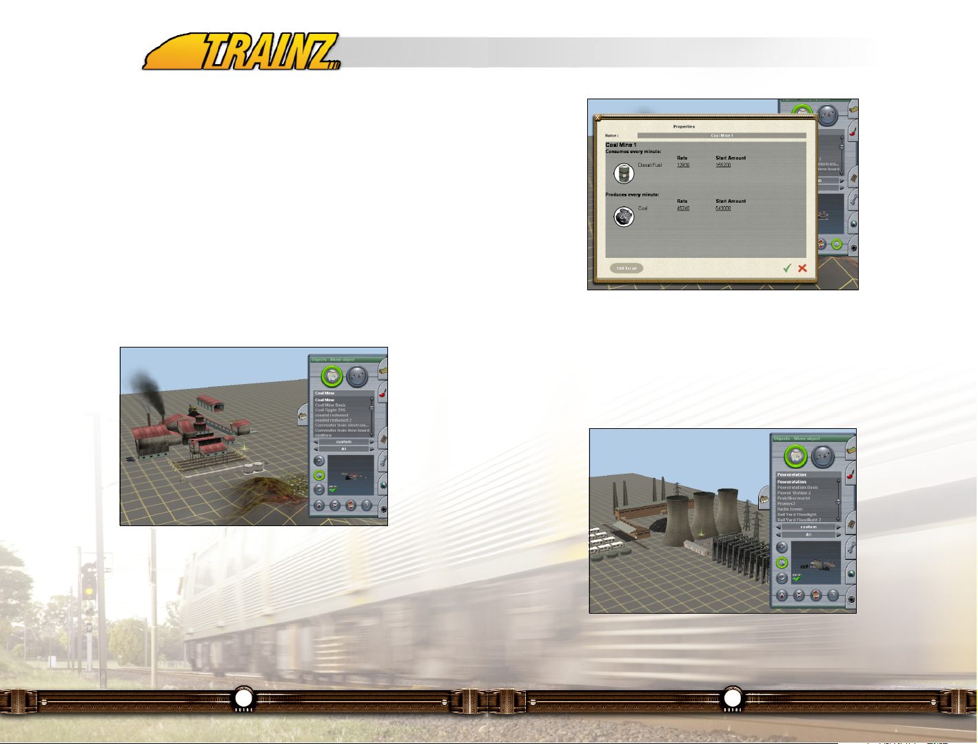
10.4.5 Give me Power
Next we'll set up a coal-fired power station. As we did for the Coal Mine, select
the Power Station. It is in the same list as you found the Coal Mine. Place it
on the other side of the baseboard (and the mountain). Move and rotate the
power station as required to line up the tracks as shown below. Set its
properties which in this case is only to name it to "Kinetic Power Co".
52
Now make sure that you are back to having only the mountain, nicely textured
in the center of the route. Use the Undo function to undo any extra texturing
that you may have been playing with.
10.4.4 Coal for Industry
Now let's place a couple of linked industries. First select the Object tab from
the tab panel and select the Coal Mine object.
You will find this under Object Type "Industrial". Make sure you are in the Add
Object mode by Click LMB on the Add Object button. Then move the view to
one side of your board and Click LMB on the map to place the Coal Mine. You
can move and rotate the object by Click LMB on the Move and Rotate buttons
respectively. To do this, Click LMB+H on the mine in the view window and then
move the mouse accordingly. Position the Coal Mine as shown below.
Next set the coal mine's properties by first Clicking LMB on the Edit Properties
button (highlighted in bright green in the screen above) and then Click LMB on
the Coal Mine. First let's give it a name. Type in "Lignite Coal Co" in the name
box. We will set the rate of coal production to 200. Do this by Clicking LMB on
the underlined default production rate and entering 200 in the pop up window.
Similarly we will change the diesel consumption to a value of 0. Set the Start
Amount for each to 0. Click LMB on the tick and we have defined our active
Coal Mine.
Page 28

55
Attach one end of the track to one of the coal mine loading tracks (there are
four) and the other end to the power station track by Clicking LMB one new
end point onto the track as shown in the screen shot above. Do the same on
the other side so you have a continuous loop. You can also smooth out your
track laying efforts by Click LMB the Move mode button in the track menu and
then Click LMB+H on any of the track spline points in the view window. Move
the mouse to move the spline points and watch as the track follows. Play with
this until you are happy with your loop of track.
Just for fun, let’s add a siding. Click LMB on the Add Track Button and click on
your existing loop of track. A new spline point appears and you can now Click
LMB again, away from the loop and create a siding.
10.4.7 Locomotives, Rolling Stock and Trains
We will now place a train of a locomotive and rolling stock on the track. Select
the Trains Tab from the Tab Panel. Then scroll down and select a locomotive
from the list of available items. Let's choose a ATSF F7A unit. Once it is
selected, Click LMB on any spot on the track you laid in the view screen to
place the locomotive. The locomotive will appear on the track with arrows
above it defining the ends of the consist and which direction will be forward
when you drive it.
54
10.4.6 Lay your Tracks
Now we will link up these two industries via a simple oval loop. The goal is to
link up the Coal Mine's loading track to the oval and run it around to the Power
Station's coal unloading track. Go to the tab panel and select the Track tab.
Choose the type of single track you want to use.
Make sure you are in the Add Track mode (the large
green button above is lit when you are in that mode).
Start laying track by Click LMB on the board where
you want to start the track. You will notice a white
circle associated with the track wherever you Click
LMB on the board. These are called Spline Control
Points. We will manipulate these points later to
move the track either horizontally or vertically.
These Spline Control Points are also attachment
points for bridges, tunnels and other spline enabled
objects.
The track is drawn between consecutive spline points. Click LMB on the map
to add another spline point and the track smoothes itself out between the two
points, a very useful feature. However, there are limits!
Page 29

57
in green below at the bottom of the tab). Then Click LMB on the locomotive in
the view panel. In the pop-up window type, click on the existing name (ATSF
F7A 2 in the screen shot below) and type in "Coal Train" to replace it. Give it
a running number of 10 by clicking on the underlined "running number" text
and typing "10".
10.4.8 Assign a Driver
Our next challenge is to assign a driver to the Consist.
Tip: This is optional as you may wish to drive your own trains in your
route. But using Drivers adds a whole new dimension to TRS2006 so
we will do that next.
Tip: If you save a session without entering any Rules, a default set of
Rules is applied for you.
Move the mouse to the top of the screen to bring down the top menu and Click
LMB on the word "Surveyor" in the menu to pull down the Surveyor menu. We
will explain all of these options later in this document.
56
Next, select the green coal car (called "coal hopper") from your list of engines
and rolling stock. Click LMB on the placed locomotive towards the back of the
loco and the coal car will appear behind the locomotive. Keep on Click LMB
on the last car in the consist to add more coal cars. Stop when you have added
5 coal cars. You will now see a consist on the track.
Let's name our consist by first Clicking LMB on the Properties button (lighted
Page 30
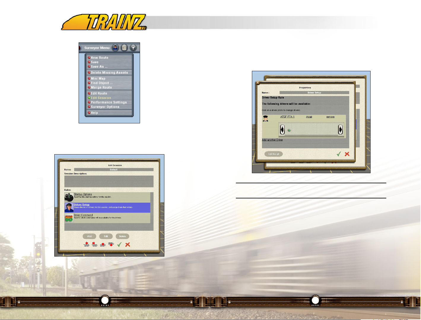
59
Click LMB on 2nd rule named "Driver Set Up Rule" such that it is highlighted
in blue. Then Click LMB on the Edit button to open the properties window for
that rule.
Tip: In any of these windows if you decide not to go through with the
change, click on the red "X" to cancel your selections.
The Driver Setup Rule is responsible for assigning driver characters to trains
for the session. It will automatically try to find every loco and have a driver
character assigned to it already. In this case, you will see how a driver
character has been assigned to the ATSF F7A locomotive.
As this is a simple session without the need for complex driver arrangements,
the automatic assignment done by the rule is sufficient, but for the sake of
configuring a rule, click on the driver character icon to bring up a list of drivers.
58
For now, Click LMB on the Edit Session option. A pop-up window named "Edit
Session" appears.
This window is where the rules that define a session’s behavior are added and
configured. As this is a new empty session, three default rules are already
included and configured so some minimal functionality is already available and
the session can be run.
Page 31

61
Ideally, you will have previously learned to use Driver mode either through the
previous chapter of this manual and the tutorial sessions. If not, this is a good
time to do so. Once you have learned how, you can load "My First Layout" into
Driver and experience the thrill of driving on a route that you have built from
scratch!!!
Tip: In TRS2006 you can try out your new route and session simply by
hitting "Ctrl-F2". This will transfer you directly into Driver. When you
leave Driver mode, you will automatically return to Surveyor so that
you can continue to work on your route having tried it out.
Well done! You have created your first Railroad by going through the steps of
building the terrain, texturing it, placing objects, laying track, putting down
consists and assigning drivers. This has been a quick peek into the powerful
capabilities of Surveyor, feel free to experiment within Surveyor and discover
its flexibility.
10.5 Becoming a Master Railroad Empire Builder
The preceding "quick start" tutorial has shown you how simple it is to get going
with Surveyor to build your railway empire. In the following section you will
learn how to further develop your routes and sessions into vast railway
empires.
60
Choose any driver from the pop-up list and click on the green check (tick) to
return back to the Driver Setup rule properties window. You will notice that the
driver character icon has changed and that the driver you chose is now
assigned to the locomotive.
Close the Driver Setup rule properties window by clicking LMB on the green
check mark at the bottom right. Then close the Edit Session window with
changes saved by clicking LMB on green check near the bottom right corner.
Sessions and the rules used to define them are looked at in more detail in
sections 11.13.7 and 11.4 of this manual.
10.4.9 Save and Drive
Once again move the mouse to the top menu and Click LMB on the word
Surveyor to pull down the Surveyor menu. Click LMB on the Save option to
save your creation and make it available in the Driver module.
Tip: Save your work in Surveyor regularly to ensure you don't lose
your work should the unforeseen happen. You can also use the Save
As option in the menu to save different versions of your route.
Page 32

63
In the list above the routes and sessions that do not have a "c" beside them
are those that have come prepackaged with the TRS2006 software. They
cannot be deleted or removed nor can they be changed and replaced. But you
can load them up and then change them and save them with a new name if
you wish.
The route and sessions with "c" beside them are ones that you have created
or that have been created by others and which you have downloaded from the
Internet. These may be changed by you and replaced or saved with a new
name. In the above example, there is one route (Ontario Northland Railway)
which is created by others and it has two session stored with it - the
Capuskasing Freight and the Polar Bear Express session.
If you wish to work with a route or session in this list, Click LMB on that route
and then Click LMB to load it into Surveyor.
Tip: Changing objects that are part of the "world" such as ground,
buildings, track, signals etc means that you're are changing the Route.
Altering the dynamic components such as locos, rolling stock, industry
parameters and Rules, means that you are changing the Session that
belongs to the Route.
62
11 - Surveyor In Depth
11.1 The Surveyor Main Menu in Detail
Let's go back to the Main Surveyor screen as shown below and explore it. At
the left in the description field will be a description of the route if the author of
the route has included one.
To create a new route from scratch, Click LMB on the Create New button as
you did in the tutorial we just described above.
On the right of the screen, you will see a list of Routes. For each route, there
may be one or more sessions. If the route does not have a session, that
means the route has been built but:
• No rules have been set to govern operations on that route.
• No consist has been developed and placed on that route.
In order to operate trains on the route (using Driver mode) you need to add at
least one train to that route. You may of course optionally add rules as well.
How to do this will all be described below.
Page 33

65
Please note that on your way back from Driver, you will be asked if you wish
to save your Driver session for reloading in future just as you might do in a
regular driver session.
11.4 The Baseboard and the Surveyor Tabs
Once you have completed the New Route setup, you will see this screen. It in
effect is the "table" up on which you build your route. The baseboard you see
here is 720 meters by 720 meters square and each grid square is 10 meters
by 10 meters in size. If you chose Imperial measures instead of metric the grid
squares still remain that size. As described later, you can use the Extend
function in Surveyor to add more baseboards and the Merge function to merge
routes.
Surveyor Tool Tabs
Down the right hand side of the Surveyor main screen are seven menu tabs
representing all the tools you need to know about to successfully make your
own route and session in Surveyor.
Leave your mouse cursor hovering over the first tab and you will notice a
yellow text box appear saying Topology 'F1'. This message is a ToolTip and
gives you information about the function of that icon. You will also notice the
64
11.2 Create a New Route
Here we will assume that you have clicked on Create New from the Surveyor
Main Menu to build a new route and associated sessions from scratch. This is
the first screen that you will see.
How to complete this screen is section 11.13.1 of this manual.
11.3 Testing Your New Route in Driver (CTRL-F2)
Before we explain how you can start to build a new route in Surveyor, let us
alert you to a handy new feature which is very useful during route construction.
In TRS2006 you can now try out your new route and session simply by hitting
"Ctrl-F2" while you are in Surveyor mode. This will transfer you directly into
Driver. When you leave Driver mode, you will automatically return to Surveyor
so that you can continue to work on your route having tried it out. This avoids
your having to save your session and then sign out of Surveyor and then load
your session into Driver.
Page 34

67
11.5 Topology Menu (F1)
11.5.1 Basic Topology Functions
The Topology Menu provides the tools for creating
various types of terrain. In this section you will
learn how to make hills, valleys, mountains, lakes
and rivers.
Tip: You will learn these features faster if you
first start a new route per the instructions
earlier in the tutorial before trying the features
to be described now.
Click on the Topology Tab (or press the F1 key) to open the Topology
Menu. Here you will see a number of different tools that can be used to
shape the terrain. Hold your mouse cursor over each one to see a short
description as well as the appropriate Hotkey to press. To see the whole
menu as in the diagram above, click on the Advanced button to expand
the menu.
Height Up (U)
Click on the Height Up (U) and notice that the Mode changes to
Height Up. Click on Height Down (D) and Adjust Height (A) to see
how each time a tool is selected, the Mode changes.
Click on the Height Up icon once again to select the Height Up tool, and notice
that your mouse cursor changes to a circle. This circle is the "area of
influence" for your cursor when using the land shaping tools.
Click LMB once near the center of your baseboard. Notice that the terrain is
stretched upwards. Next, Click LMB+H, and the terrain continues to rise up as
long as you hold the LMB down. Notice how the hill becomes very steep and
the base of the hill is the approximate size of the cursor circle.
Click LMB on the Radius Tool ("+") to enlarge the circle of influence to its
66
"Hotkey" information ('F1') telling you which keystroke you can press as an
alternative to clicking on the icon. Most functions in Surveyor have a ToolTip
and Hotkey associated with them.
If you are in doubt as to what a particular icon will do, simply hold your mouse
over it and the ToolTip will tell you what action that icon performs. Hotkeys in
this document are shown in brackets after the tool description.
Page 35

69
Combined with the zoom function (Page Up, Page Down), spinning the
camera (arrow or cursor keys), and adjustment of the radius and sensitivity
dials, you can now make a wide variety of different hills and valleys. Practice
this until you are comfortable to move on.
Get Height (G)
Select Get Height (G), then Click RMB on the side of a hill. Notice that
the number in the Height Value field changes. You have captured the
height of the spot you clicked on. This is useful when you want to then go to
another spot and set the spot to the same height.
Watch the Height Value field change as you Click RMB on different parts of the
terrain.
Use Height (H)
Click on Use Height (H) Then Click LMB to apply the selected Height
Value to the terrain. The Use Height tool creates a plateau at your
selected height and the radius of your cursor circle determines the amount of
land that is leveled at one time.
Click LMB+H then move your mouse around the terrain to plateau a broader
section.
Plateau (P)
Plateau (P) works in a similar fashion, and simply creates a plateau at
the current height of the compass. Click LMB on the side of a hill to
create a plateau at that level by raising or lowering the terrain.
As an alternative to Get Height to select a Height Value, you can also enter
specific height in the Height Value field. You can enter positive or negative
values. Negative values allow you to depress the terrain.
Add Water (W)
To create a "riverbed", make your circle radius as small as possible.
Next, enter -10 in the Height Value field. Then click on Use Height. Now
68
maximum size. Click LMB and hold near the compass icon once more. The hill
this time is a lot wider and flatter. Click LMB on the Radius Tool ("-") to reduce
the size of the circle of influence.
Tip: The "+" and "-" are the keyboard keys between the "0" and
"backspace" keys on your keyboard. They are not the keys on the
number pad at the right of your keyboard.
Zoom Out (Page Down) so that you can see the whole circle. In Surveyor, you
will often need to zoom in and out and use the arrow keys to rotate your
camera to get the best view of what is happening. Whilst holding the LMB,
move the mouse around the terrain and the hill "follows" your cursor. Zoom In
(Page Up) for a closer view.
Next, increase the sensitivity by moving the Sensitivity Dial ("]" and "[") to the
maximum setting and Click LMB. Now the hill grows a lot faster. You may need
to zoom out again (Page Down) to see the whole hill.
As you make hills, you will find you need to Click RMB to move your camera
position and also orient the camera in the direction you wish to face by using
your arrow keys. A little practice makes hill creation a breeze.
Height Down (D)
Height Down works the same as Height Up tool. Firstly move to a flat
area then make an indentation by Clicking LMB where you want the
terrain to be lowered. Again, notice that size of the cursor circle
determines the amount of land that is lowered and the sensitivity determines
how quickly it lowers.
Adjust Height (A)
Adjust Height (A) allows finer control of the up and down movement.
Click LMB and hold then push your mouse away from you to raise
the terrain. Click LMB and hold then pull the mouse towards you to
lower the terrain.
Page 36

71
your mouse forward and back, adjusting the water texture height until it is the
appropriate height. Note how it properly fills the riverbed as you move the
water downward.
Remove Water (Q)
Click LMB on Remove Water (Q) and you then delete the water texture
one panel at a time by Clicking LMB on each water panel.
11.5.2 Advanced Topology Functions (Shift-F1)
The Advanced features menu can be opened and
closed by using Shift-F1 or clicking on the
Advanced Tab.
Extend Section (X)
Navigate to the edge of a baseboard by
Clicking RMB to move the compass. Then
select the Extend Section (X) tool. Click LMB in
the void just off the edge of the baseboard to add
another baseboard in that direction.
Bring up the Surveyor Main Menu by clicking on
the word Surveyor on the top menu which drops
down if you move your cursor to the top of the screen.
70
make your riverbed by Click LMB+H, then "painting" the new height along the
terrain creating your riverbed as shown below.
Now Click LMB on Add Water (W) and paint the water texture along the
riverbed by Clicking LMB and moving your mouse around. The radius of the
cursor circle determines the texture panel size. You results will look like that
shown below where we have partially completed the "water painting" job. Paint
enough squares so that they will cover the area of your riverbed.
Adjust Water Height (E)
At first as you see above, the water "floats" above the terrain. Adjust
Water Height (E) works like the Adjust Height tool. Select the Adjust
Water Height tool and Click LMB and hold (on the water texture) then drag
Page 37

73
Fill Area (F)
Scroll through the Displacement Maps (by clicking on the left and right
arrows) until you find one called the Volcano, then click on Fill Area (F).
The terrain is instantly transformed into the shape determined by the
grayscale images of the displacement map chosen. In this case, we have our
volcano.
Note: If you can't Click LMB on this button, it is probably due to your
not having used Select Area (B) to select an area to fill.
72
Select Mini Map (Ctrl-M). You will see a mini map showing 2 baseboards.
Zoom in and out by clicking on the "+" and "-" icons.
Tip: The "+" and "-" are the keyboard keys between the "0" and
"backspace" keys on your keyboard. They are not the keys on the
number pad at the right of your keyboard.
Close the mini map by clicking on the Red Light (Ctrl-M) to toggle back to the
full screen view.
Navigate to another edge and add two more baseboards then press Ctrl-M to
view the mini map once more. Navigate around the mini map by Clicking RMB.
Notice the main map also moves. This is very useful for navigating on large
maps. Use Ctrl-M to close the mini map once more.
Delete Section
Click LMB on the Delete Section button. Then Click LMB on any
baseboard section to delete it.
Displacement Maps
The final group of Topology tools relates to using a displacement map. A
displacement map is a grayscale image used to create an instant height map.
Select Area (B)
Click on Select Area (B). Click LMB and drag the mouse to make a large
square as shown below. The size of the square (or it can be a rectangle)
determines the area that will be affected by the next operation.
Page 38

75
11.6 Paint Menu (F2)
11.6.1 Basic Paint Functions
The Paint Menu provides access to a wide
variety of ground textures. Textures in
Surveyor are "bitmaps" which are created
to look like various ground types such as sand,
grass, rocks or gravel. You can even create
your own textures using a simple paint
program or a digital camera. (The resultant
.bmp file must be 128x128 pixels)
Click on the Paint Tab (F2) to open the Paint
Menu. You will see a number of default
textures, grouped by region. Use the slider
button to scroll through the list.
Click the left and right arrows to view textures from the different regions.
Click on one of the textures, and you will see a copy of it appear in the small
current texture window. Click LMB on the terrain and use your mouse as a
paintbrush to paint on the texture.
Scroll through the textures until you find a striped texture. Paint a section of
terrain. You can see that a complex texture pattern makes easy work of
creating stunning ground textures.
Rotate the Direction Dial 90 degrees. Apply the texture again. Notice how the
texture direction has changed.
Hold down the "[" key and apply the texture once more. Notice the direction
dial is spinning and the texture is being applied in various directions. This tool
helps to eliminate repetitive patterns in your textures when you don't want
them.
74
Click Undo to remove the volcano.
Repeat the process using the Valley gray scale map to build a valley. Then
move the Direction dial and increase the Threshold dial. Click LMB on Fill Area
once more. This time the valley is bigger and faces a different direction. By
holding Shift whilst selecting your area, larger areas are selected at one time.
Cancel Selection (D)
Click LMB on Cancel Selection (D) to cancel the selection.
Making Your Own Displacement Maps
You can also make your own displacement maps using a simple paint program
(e.g. MS Paint) and then drop them into the \World\Custom\Displacements
folder in your TRS2006 directory to make them accessible.
Page 39

77
11.6.2 Advanced Paint Functions (Shift-F2)
The Advanced Tab (Shift-F2) has a "favorites"
texture palette. Drag and drop textures from
the top palette into the box in the advanced
menu area to build up a set of your favorite
textures for ease of access. Just Click LMB+H
upon a texture and drag it to the box below. To
remove a textures from the favorites box, just
Click LMB+H on the texture and drag it out of
the box and then stop holding the LMB.
Select Area (B)
You can also texture a rectangular area
by clicking on the Select Area (B) and
using the mouse to drag a rectangle of any
size.
Fill Area (F)
Then Click LMB on a texture in the favorites box and use the Fill Area
(F) tool to texture the whole rectangle. If you do not select an area first,
Clicking LMB on Fill Area (F) and Surveyor will fill all areas on which there are
no textures with the selected texture.
Note: If you can't Click LMB on this button, it is probably due to your
not having any textures in the favorites box.
Cancel Selection (D)
Click LMB on Cancel Selection (D) to cancel the selected area.
76
Now move the Scale dial to the minimum setting and apply the texture, then
move the scale dial to the maximum setting and notice the difference when
you apply the texture this time. You can avoid repetitive texture patterns and
create ultra-realistic effects by using the scale and direction tools along with
choosing the right textures.
Get Texture (G)
Click on the Get Texture (G) tool then Click LMB on a texture already
painted onto your terrain. Notice the current texture window changes to
show the newly selected texture. This is a useful way to find a texture that you
have already used without scrolling through all the textures to find it again.
The Radius Dial ("+" or "-") changes the area of influence of your cursor circle.
Use the larger radius for quicker painting and the smallest radius for more
accurate and detailed work.
Tip: The "+' and "-" are the keyboard keys between the "0" and
"backspace" keys on your keyboard. They are not the keys on the
number pad at the right of your keyboard.
Fill Grid (L)
The Fill Grid (L) will fill all unpainted areas of an entire baseboard with
one texture. This is useful for finishing off an area where fine texturing
is not required.
Page 40

79
Tip: If there is a green checkmark with the letters "IND" shown in the
lower left corner of the Viewer window, this is an indication that this is
an "interactive" piece of industry capable of participating with
"interactive" rolling stock.
Move Object (M)
Click on the Move Object (M) and Click LMB+H on any object and then
drag the object around the terrain to new positions.
Rotate Object (R)
Now click on the Rotate Object (R) and Click LMB+H and move the
mouse left and right to rotate the objects. Note that a display shows you
the number of degrees of rotation.
You can use the move and rotate tools to create rows of trees or to align
houses next to a road. You can set objects to "randomly rotate" or not by
choosing the Randomly Rotate option in the Surveyor Options menu in the
Surveyor Main Menu.
To find a particular object in the list of objects, click on the Object Selection
text box, and then type the first few letters of the object name. Type in "tree"
and the list automatically positions alphabetically at "tree". Click on the Up and
Down arrows (or use the "+" or "-" keys) to scroll up and down the list.
Tip: The "+" and "-" are the keyboard keys between the "0" and
"backspace" keys on your keyboard. They are not the keys on the
number pad at the right of your keyboard.
Above the Object Viewer Window are the Object Region and Object Type lists.
Scroll through and select either a region or an object type or both in order to
shorten the selection list.
78
11.7 Objects Menu (F3)
11.7.1 Object Management Functions
There are a huge number of objects
in TRS2006 that you can place onto
the terrain. There are two different
types of objects - objects and splines. We'll
explain spline objects later. For now we will
concentrate on single objects.
Open the Objects Menu by clicking on the
Objects Tab (F3). The default mode is Add
Objects
Begin by scrolling through the list of objects by
clicking on the left and right arrows of the object
list. The selected object shows as a rotating 3D
object in the viewer window.
Note: You can control what is shown in your list by selecting specific
Object Regions (such as USA) and Object Types (such as Trackside).
Add Object (A)
Check that you are in Add Object mode, or Click LMB on Add Object (A)
to select this mode. Click LMB on the terrain and the selected object is
placed wherever you click. You can repeat this several times quickly adding a
number of trees or buildings.
Tip: It is easy to click twice and get multiple copies of your object. Just
use Undo to delete the unwanted copies of the objects.
Page 41

81
Delete Object (D)
Select Delete Object (D) then Click LMB to delete an object. Continue
Clicking LMB to delete a number of objects. If you click on the wrong
object, click on Undo (Ctrl-Z) to undo the last action and replace the last
deleted object.
Edit Properties (N)
Click LMB on Edit Properties (N). Then Click LMB on any object in your
route. A menu will then open up allowing you to edit the properties of
the object. For wimple objects, this usually involves naming the object if you
wish.
For more complex operating industries, you are given the opportunity to
change production and consumption rates for resources and other properties
as we experienced in the earlier tutorial with the power plan and the coal plant
objects.
11.7.2 Special Object Types
As well as the regular objects that are static and exist primarily for cosmetic
purposes, there are also a range of interactive and special object types with
unique features. These objects usually have track included that can be linked
to the track on your main route.
Industries
An industry is a scenery item with track that also produces and consumes
products. Train vehicles can load and unload products at an industry allowing
real world railroad activity (i.e. the transportation of goods) to be simulated.
The products produced and consumed by an industry can be viewed and
tweaked by using the Edit Properties button as mentioned above.
Section 10.4.4 of this manual has a simple example showing how to place and
integrate an industry into a route.
Tip: Industries can be easily found in the scenery object list by
selecting the "Industry" category.
80
Get Object (G)
Click on the Get Object (G) tool and then Click LMB on an object
already placed on the terrain. Notice that the object selected now
appears in the selection window.
Change the mode to Add Object (A) and Click LMB again on the terrain where
you wish to place another copy of the newly selected object.
Adjust Height (H)
When placed on a route, Objects are placed at ground level at that point
in the route. If the ground is raised the object follows it. But you can
place an object at a relative height to the ground at any point.
Click LMB on Height Adjust (H) to enable the adjustment of the height of any
Object. Note that only objects which have been designed to be height
adjustable will allow you to adjust their height. So if you cannot adjust the
height of an object, the likely reason is that it wasn't designed to do so.
While in the flight of fancy shown below, we have height adjusted a station to
make it defy gravity (only in TRS2006!!!), this function is very useful. For
example, you can place objects on top of each other such as a building on a
platform.
Page 42
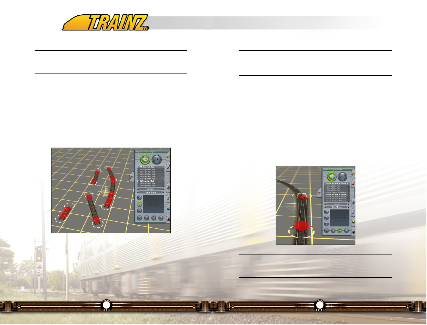
83
Tip: Fixed track pieces can be easily found in the scenery object list
by selecting the "Fixed Track" category.
Note: Gradients are not really supported with fixed track. It is
advisable to use fixed track for flat areas only.
Animated Junctions
New to TRS2006 are animated junctions. These junctions differ from normal
junctions in that they are pre-defined fixed track pieces and have animated
components. As an animated junction is a pre-defined fixed track piece, extra
detail like guide rails can also be present in an animated junction.
Animated junctions are added and manipulated on the Surveyor baseboard in
the same way fixed track pieces are.
Note: You will find the animated junctions in the "Fixed Track"
category. The names of all animated junctions included with TS2006
are prefixed with "Turnout".
82
Note: To be of any use, an industry’s track must be connected up to
your railroad and to load/unload, the vehicles used must be capable of
carrying that particular product.
Fixed Track
Fixed track scenery items are fixed, non-flexible segments of track and can be
thought of as the Trainz equivalent to the sectional track model train
manufacturers have.
A piece of fixed track can be placed like any ordinary scenery object and then
connected to normal track splines. It is also possible for fixed track pieces to
snap together when one piece is moved in close proximity to an end point of
another.
The end points of a fixed track are identified by the red arrow seen hovering
above the track.
When rotating a piece of fixed track, other pieces of fixed track attached to it
will also be rotated resulting in the track pattern being maintained during
rotation. The same also applies for moving connected pieces of fixed track.
Page 43

85
Crossings support animated gates that are automatically activated as a train
enters and leaves a proximity region surrounding the crossing.
The operation of crossings is automated and even the Carz will stop when the
gates are lowered for a train to pass through.
Tip: The names of all crossings included with TS2006 are prefixed
with "Tside Crossing". There is no crossing object category.
Backdrops
Backdrops are a new object type introduced with TRS2006 that are rendered
regardless of the view distance settings. This means they will always be visible
and won’t disappear like other distant scenery items, thus making them
suitable for scenic backdrops.
Tip: The names of all backdrops included with TS2006 are prefixed
with "Backdrop". There is no backdrop object category.
84
Turntables
Turntables are scenery objects with multiple incoming pieces of track where a
special traverser track segment (usually rotating) can move around to offer
access to all track pieces. Simply placing a turntable object on the baseboard
and connecting the tracks is all that is required to have it functioning.
Tip: The names of all turntables included with TS2006 are prefixed
with "Tside Turntable". There is no turntable object category.
Crossings
A crossing is a scenery object that allows rail track and a road to cross each
other. As well as being a scenery object that can be connected to the route’s
track, a crossing can also be linked up to road splines (see section 17.7.3 for
details on road splines), as the screenshot below shows.
Page 44

87
Move Spline (M)
You can move any spline point by selecting the Move Spline (M) tool
and then Click LMB+H and dragging the spline point to a new position.
Sometimes when you place a spline point, the spline "snaps" to a nearby
spline point and creates a curved spline. To avoid this happening, hold the
Shift key down when placing the spline points. This "forces" the spline point to
go where ever you tell it to go.
You can also use Shift-Click LMB to a spline to be placed on top of another.
This is useful to create a right angle turnout such as a fence.
Get Spline (G)
Click LMB on the Get Spline (G) tool and then Click LMB on a spline
object already placed on the terrain. Notice that the spline object
selected now appears in the selection window. This is a quick way of finding
the spline you want in case you wish to place additional ones into your route.
Change the mode to Add Spline (A) and Click LMB again on the terrain where
you wish to place the newly selected spline object.
86
11.7.3 Spline Management Functions
The next mode to explore is Spline Mode.
Splines are generally long thin objects such as
roads, power lines, fences and rows of trees.
They consist of two or more "spline points"
denoted by white circles. These spline points
can be placed any distance apart and the
spline object is then "stretched" between
the spline points as you place them on the
route.
Spline Mode (S)
To enter Object Spline mode, Click
LMB on the large Spline Mode (S)
button at the top left of the tab menu.
Add Spline (A)
When you Click LMB on Spline Mode
(S), the default selection will be Add
Spline (A).
Click LMB on the terrain to anchor the first spline point, and Click LMB again
some distance away to place the second spline point. You will see white circles
at each end of the spline. These spline points determine the points of a spline
that may be selected or moved. For example, in the picture below, we have
paced the "Powerline B" spline on the route.
To extend the spline further, Click LMB again on the last spline point, then
Click LMB once more nearby to extend the spline.
You can simplify this process by holding down the Ctrl key then placing several
spline points. Release the Ctrl Key and place your final spline point to anchor
the spline in place.
Page 45

89
11.7.4 Advanced Spline Management Functions (Shift F3)
Click LMB on the Advanced Menu (Shift F3) to
access even more tools. A drop down menu is
then revealed as shown at the bottom of the
tool tab above. This provides you with the
following tools.
Spline Height (H)
The Spline Height (H) tool can be used to raise or lower the height of
certain types of splines (for example catenaries or road bridges). Click
LMB on Spline Height then Click LMB+H on a spline point (the white circle)
and drag the mouse forward or backwards.
Delete Spline Point (X)
Click LMB on Delete Spline Point (X) and then Click LMB on a white
spline circle to remove unwanted spline points. You cannot delete an
end spline point, but you can delete the whole section using the Delete Spline
(D) tool.
Insert Spline Point (I)
Click LMB on Insert Spline Point (I) then Click LMB between two
existing spline points. Notice that a new spline point is created. You may
need to zoom in closer in order to insert a new spline point.
Note: Don't overuse spline points as each one will add load onto your
graphics card and may noticeably degrade performance.
Smooth Spline (S)
Lay a road spline down on level ground on your route using at least four
spline points. Use Spline Height (H) to pull up two spline points in the
middle of the road. The road now floats above the ground.
Click LMB on Smooth Spline (S). Now Click LMB on the raised spline section
and the spline is instantly raised up to meet the road. To make a few minor
adjustments, click LMB again on the road a few more times. Sometimes it
88
Delete Spline (D)
Click LMB on Delete Spline (O) then click on a section of spline
between two adjacent white circles to remove unwanted spline
sections. If you delete a section that is not an end section of a spline, the
spline will be split into two splines.
Split Spline (Q)
If a spline is already curved, you can split it into two sections by using
the Split Spline (Q) tool. Simply Click LMB on the middle spline (or any
non-end spline point) and you now have two separate splines.
Toggle Traffic
Many of the roads (which are splines) that you will be placing on
your route will have vehicles (affectionately known as "Carz")
traveling on them automatically. You will see them moving in Surveyor after
placing the roads. Clicking LMB on Toggle Traffic turns all traffic off on these
types of roads. Clicking LMB on the button again will have traffic resume. If the
Toggle Traffic mode is ON, the button will be lit up in a bright green color.
Please note that when you toggle traffic on and off, it affect all spline roads on
your route.
Roads are placed as splines as shown below.
Page 46

91
Tip: Place a rail crossing as you would do a normal object and then
connect track segments to the track spline points. Next, connect road
splines to the road spline points. If you have laid the crossing correctly,
when you load the map into Driver, road traffic will stop and allow your
trains to run through the crossing.
Tip: To get your catenaries to match your track in an electric route, it
is generally best to place the spline points directly on top of the track
spline points. This ensures that the curvature matches that of the track
and makes it easier to match the height of the track also. Whilst laying
your catenaries, press Alt-O to show the track spline points then hold
the shift key to allow placement of the catenary spline on top of the
track spline.
Get Vertex Height
Click LMB on the Get Vertex Height and Click LMB on the highest spline
point on your spline. The height is displayed in the Height Value box.
Apply Vertex Height
Click LMB on Apply Vertex Height then Click LMB on another spline
point. The spline point is raised to the same height as you first vertex.
This is useful for ensuring level spline segments.
Remove Gradient
Click LMB on Remove Gradient and then Click LMB on a spline section
to remove the gradient between two spline points.
90
takes a few passes to get the road just right.
Find another level untouched area of your baseboard. Next, make and texture
a small hill using the Topology tools.
Lay a single section of road spline over the top of hill with a single pair of spline
points at either end. Note that it clings to the surface of the hill. Now Click LMB
on Smooth Spline (S) and then Click LMB on the road. As shown below, this
will level the terrain between the two spline points, thereby creating a cutting
through the hill to flatten the road.
Smooth Spline (S) levels the track between two spline points, bringing the land
up or down to match the leveled spline.
Tip: Turntables and railroad crossings are actually standard objects
rather than track objects but they both have spline points so that you
can attach spline objects such as roads and track to them.
Page 47
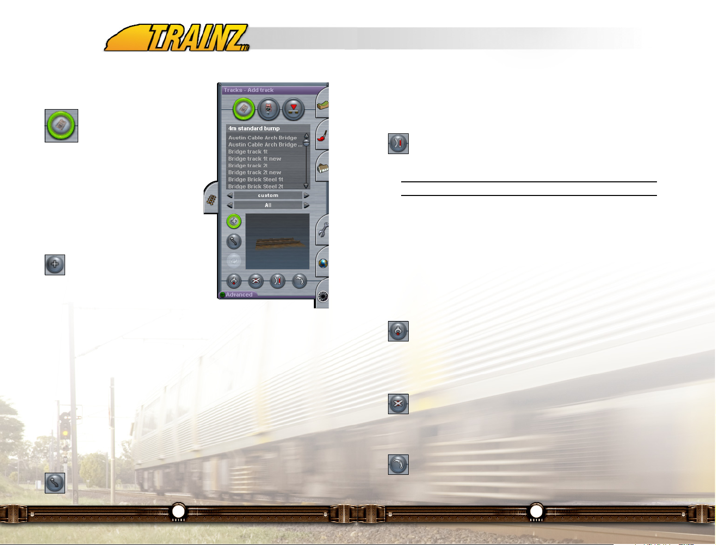
93
your mouse around the terrain and notice how the track bends. The shape of
the curve is also affected by how close the spline point you are pulling is to the
next spline points.
Straighten Track (B)
Click on Straighten Track (B) and then Click LMB on a bent section of
laid track. Notice that the section of track straightens between the two
spline points and the next track segment is also affected.
Note: Double track cannot be straightened.
Click again on the straightened track and it returns to a curved track. This tool
is especially useful when creating turnouts and yards and tidying up messy
track sections.
Choose a different type of track by clicking on either the Track Region or Track
Type dialogue box and scrolling down the list until you find a bridge. Lay a
short section of bridge on the flat ground just as you did for the single track.
Get Track (G)
Click on Get Track (G) and then Click LMB on your original track. The
bridge showing in the selection window is replaced by the track. Press
"A" to change the mode to Add Track and you are ready to lay another section
of track.
Delete Track (D)
Click on Delete Track (D) then click on the bridge section to delete it.
(Note: any trackside objects you place on a track segment will also be
deleted when the track is deleted).
Split Spline (Q)
Click on the Split Spline tool (Q) and click on a middle spline point
(white circle) in the track. The track breaks in two at that point.
92
11.8 Track Menu (F4)
11.8.1 Track Mode Tools
Learning how to lay track, place
signals and create turnouts can be
the key to running a successful
TRS2006 Driver session. Track sections in
TRS2006 are made up of flexible length track
pieces created by placing 2 spline points. We
call this "flexi-track" and it makes laying any
lengths of track extremely simple. Select
the Track Menu (F4) and the default
selection will be Track Mode (T).
Add Track (A)
The Add Track (A) tool should already be
highlighted, so you are ready to lay your
first length of flexi-track. Click on the left or right
arrows of the track selection dialogue to select
the type of track you wish to lay, then Click LMB on the baseboard where
you want to anchor your starting point. (We suggest you start with Single
Track).
Click LMB again a short distance away to place another spline point. A straight
section of track has now been laid between the two spline points.
To extend the track further, Click LMB again on the last spline point (the white
circle), then Click LMB once more nearby to extend the track. Unless all three
spline points are exactly in a straight line, you will notice that the track is now
curved. To connect two sections of track, just drag the end spline point of one
on top of the end spline point of another and they will automatically connect.
Move Track (M)
To bend the track in any direction, select the Move Track (M) tool and
then Click LMB and hold on one of the white spline point circles. Drag
Page 48

95
Use Move Track (M) to grab the new spline point and move it around until you
are happy with the shape of the turnout. You now have a perfectly created wye
turnout
Note that a turnout lever has automatically been added to the Turnout. The
Red and Green arrows indicate which way the turnout will be set when you
begin to operate your new route. To change the turnout’s set direction, either
Click LMB on the turnout in Mini-Map mode or use the "Junction Direction" tool
as discussed in section 11.8.5.
The Switch lever can be deleted using the Trackside Object Delete function.
But you must replace it with another of your choice if the Turnout is to function
properly.
Later we will show you how to change turnout levers and add signals to
complete the job.
Tip: If you are trying to move or delete a piece of track and it won't
move or delete, you will receive an audible beep. This means that the
track is attached to a non-movable item such as an interactive industry
object, rail crossing or perhaps even a loco or item of rolling stock. In
the case of vehicles, they need to be moved at least 2 spline points
away from the section of track you wish to edit.
Animated Junctions
Animated junctions are supported in TRS2006 but cannot be created as track
splines. Instead, you need to place an animated junction object on the
baseboard. See section 11.7.2 for details.
94
Creating a Turnout
Depending on which part of the world you live in, there are different names for
where one section of track branches off from another. Sometimes these are
called turnouts, junctions, points or switches. We call them turnouts in this
document.
This section will teach you the basics of creating turnouts.
To create a wye turnout, begin by laying two spline points.
Next, Click LMB to the left of your first section of track and drag the new
section towards the existing track.
Click LMB about half way along the first track and the track bends to the shape
of a turnout. You have just created your first turnout.
To tidy up the turnout and make it look a little better, select the Straighten
Track (B) tool then click on the lead out track to straighten the section leading
into your new turnout.
Add a new spline point to your turnout by going to the Advanced Menu (Shift
F4) and selecting the Insert Spline (I). Click on the left-most track to add the
new point.
Page 49
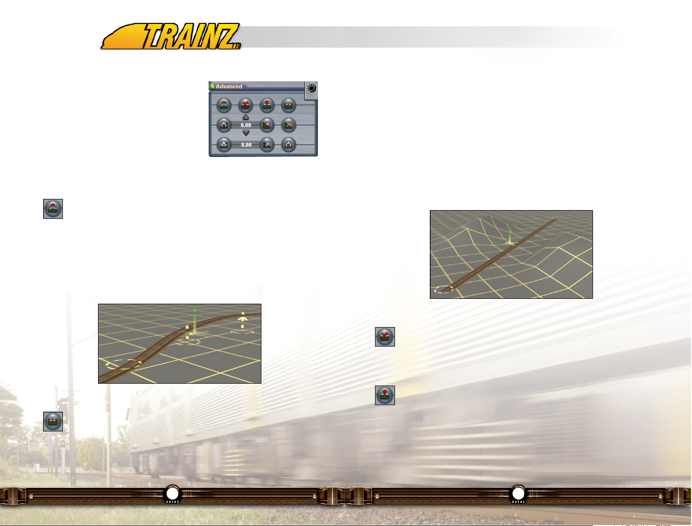
97
Find a level untouched area of your baseboard. Next, make a small hill using
the Topology tools.
Lay a single section of track over the top of hill with a single pair of spline
points at either end. Note that it clings to the surface of the hill. Now Click LMB
on Smooth Spline Height (S) and then Click LMB on the track. As shown
below, this will level the terrain between the two spline points, thereby creating
a cutting through the hill to flatten the track.
Smooth Spline (S) levels the track between two spline points, bringing the land
up or down to match the leveled track.
Delete Spline Point (X)
Click LMB on the Delete Spline Point (X) and Click LMB on a track
spline point (not a spline end point as they cannot be deleted). Notice
that the spline point is removed and the curvature is also affected.
Insert Spline Point (I)
Click on Insert Spline Point (I) to add a new spline point. Once again the
track curvature is affected. Careful placement of spline points is one of
the secrets to good track laying. But be careful not to put in too many as the
more you have the greater the complexity of the route and the harder your
computer has to work to give you smooth operations.
96
11.8.2 Advanced Track Mode Tools (Shift-F4)
In TRS2006, there are two ways you can lay
track. Either lay the track and bring the land up
to meet it, or create the land, then lay your
track over it. We'll show you both ways using
Advanced Track Menu (Shift F4).
Click LMB on the Advanced button to drop
down the Advanced Track Menu.
Adjust Spline Height (H)
Begin by laying a short section of curved track using 4 or 5 spline
points. Click LMB the Adjust Spline Height (H) and Click LMB and hold
on a track spline point. Drag your mouse forward and back to raise and lower
the spline point. Raise the track off the ground, and then bring the camera
down close to the ground to get a better view.
As you can see below, the track spline points will have arrows attached to
them showing you the height of the track above the ground.
Smooth Spline Height (S)
Select the Smooth Spline Height (S). Click on the raised track section
and the ground is instantly raised up to meet the track. To make a few
minor adjustments, click again on the track a few more times between each
pair of spline points. Sometimes it takes a few passes to get the track just
right.
Page 50

99
Track in TRS2006 usually tries to "average" a curve so you can use Straighten
Track to "end" a curve. This stops the track trying to bend back in the other
direction.
Even using Show Curve Radius, creating a nice curve can be a little tricky at
first. Here are some tips. Move your camera vertically above the track and
zoom out. Lay down five spline points in a gentle 90-degree curve. The curve
is probably a little wobbly.
Use Move Track (M) to straighten the ends then use the Straighten Track (B)
to straighten the two end sections. You now have a nice consistent curve
through 90 degrees.
11.8.3 Building Bridges
Bridges and tunnels work much the same way as for normal track but can be
a little harder to lay due to the type of terrain involved. It is sometimes easier
to make the bridges and tunnels on flat ground then move them into place.
Select the Track Type "Bridges" by clicking on the Track Type arrow keys, then
scroll through the list of bridges until you find the bridge type you are looking
for.
To place the bridge, select the Add Track (A) tool and lay the bridge just like
you did for the track by clicking to place spline points. It is best to lay bridges
between two hills although you can lay the bridge and then remove the terrain
beneath it.
Below we have placed the bridge called "Bridge Truss Spline" on some flat
terrain.
98
.Get Gradient (J)
Next, select the Get Gradient (J) and Click LMB on your raised track
section between two track spline points. The gradient between those
points is shown in the Gradient Value box as a percentage slope. The value 2
means 2% or 1 in 50.
Apply Gradient (K)
Enter in a new gradient value in the Gradient Value text box, then Click
LMB on Apply Gradient (K). Click LMB on the track near your first spline
point to raise the track.
Now Click LMB on Undo (Ctrl-Z) and then Click LMB near the 2nd spline point.
Notice that the gradient has now been applied in reverse. The rule is that the
gradient is always applied "away" from the spline point closest to where you
click.
Remove Gradient
Click LMB on remove Gradient and then Click on a track section to
remove the gradient between two track points.
Get Vertex Height
Click LMB on the Get Vertex Height and Click LMB on the highest spline
point on your track. The height is displayed in the Height Value box.
Apply Vertex Height
Click on Apply Vertex Height then Click LMB on another spline point.
The spline point is raised to the same height as you first vertex. This is
useful for ensuring level track segments.
Show Curve Radius
Next, click on Show Curve Radius then move your mouse along a track
segment. The curve radius is shown next to your mouse cursor. The
number is the radius measured in meters so a low number means a tight curve
and a high number means a straighter track.
Page 51

101
To create a bridge that is level, you can use the Get Vertex Height tool. Click
on the spline point at one end of the bridge and you will notice the Height
Value is entered into the Spline Height dialogue box.
Click on the Apply Height tool then click on the other two spline points. This
applies the same height to each of those spline points.
11.8.4 Building Tunnels
Tunnels work in the same way as bridges. Repeat the steps above but firstly
select a tunnel rather than a bridge. For your first tunnel, lay it on a flat section
of ground so that the hills don't interfere with the operation. (You can always
add the hill afterwards). Here is an example of the double track "Tunnel Stone"
placed on flat terrain.
100
You can insert a spline point in the middle of the bridge using Insert Spline
Point (I) and then Clicking LMB on the bridge section to insert the new point.
Click on Move Track (M) and Click LMB and drag the middle spline point. This
allows you to bend the bridge. Don't bend it too far or it will "break". Below we
have inserted a spline point into the middle of the bridge and curved it.
When you depress the ground under the bridge, the bridge piers will reveal
themselves as shown below. Note that we have painted the ground and added
water as well.
Page 52

103
11.8.5 Trackside Object Management
Trackside Mode (Y)
The second mode in the Track Menu
is Trackside Mode. Click LMB on
Trackside Mode (Y) to change the
Track Tab menu to the Trackside Mode menu.
Add Object (A)
To add a trackside object Click LMB
on the Add Object (A) button. The
select the object you wish to place from the list.
Click LMB at one or the other side at some
point of the track. Your object will be placed
beside the track and will be "attached" to it. So
if you move the track it will move with it.
Tip: Some of the most important Trackside objects are the AI Direction
Markers. These are used by the Drivers for navigating (pathfinding)
around your route. A Driver under AI control will not enter a track
segment against the direction of the AI Direction Marker. Therefore
these are useful for controlling Northbound or Southbound traffic etc,
but, used incorrectly, they can also provide barriers stopping Drivers
getting to where you want them to go.
Move Object (M)
Click LMB on Move Object (M). Then Click LMB+H on a Trackside
Object on your track. Drag your mouse along the track to move the
object to a different position.
Rotate Object (R)
To change the side of the track for a trackside object, click on the Rotate
tool (R) and Click LMB on the object. It will switch sides of the track and
rotate 180 degrees. The direction that a trackside object faces is controlled by
102
Once you have 3 spline points in a tunnel, select Move Track (M) and Click
LMB and drag the middle spline point to create a bend in the tunnel. Notice
that in TRS2006, the tunnel exits "snap" to the terrain at 45-degree
increments. You may need to re-route your track to align it correctly to the
tunnel entrance and exit.
Ensure that you hide the tunnel exit properly by using the terrain Height Adjust
tools and the track Smooth Spline tool to tidy up the entrance.
To join track to bridges or tunnels you should always use single track (even for
a double track, bridge or tunnel). Lay the spline point away from the bridge first
and then move the track towards the end spline. The track will snap to the
bridge object. Use Smooth Spline to tidy up the terrain.
Page 53

105
11.8.6 Signaling Systems
You can place signals on your route by choosing them from the Trackside
menu. They may be moved and rotated in the same fashion as other trackside
structures, and like other objects, they are categorized by Region.
Australian & UK signals appear on the left of the track, USA signals appear on
the right. European signals vary depending on the track.
104
the selection of Geographic region for the route.
Get Object (G)
Click on the Get Object (G) tool and then Click LMB on an object
already placed at the trackside. Notice that the object selected now
appears in the selection window.
Change the mode to Add Object (A) and Click LMB again at another point on
the track where you wish to place another copy of the newly selected object.
Delete Object (D)
Select Delete Object (D) then Click LMB to delete a trackside object.
Continue Clicking LMB to delete a number of objects. If you click on the
wrong object, click on Undo (Ctrl-Z) to undo the last action and replace the last
deleted object.
Junction Direction (J)
If you have a turnouts placed on your route, each should have a switch
lever attached to it. The switch lever at a turnout has a green and red
arrow. To change the default direction of travel (for when you drive on this track
in the Driver module), Click LMB on the Junction Direction (J) tool and then
Click LMB once on the green and red arrows. The direction is now changed
(green denoting the default direction of travel).
You can also make 3-way turnouts by simply adding a third track to the
turnout. There are now three direction arrows.
Define Name (N)
Next, select the Define Name (N) tool and click again on the turnout. A
dialogue box opens allowing you to type a name for the turnout in the
box. Click the Check (proceed) icon to save the name and proceed.
Page 54

107
11.8.7 Trackmark and Trigger Management Tools
Trackmark Mode (V)
The third mode in the Track Menu is
Trackmark Mode. Trackmark mode is
used for the management of
Trackmarks and Triggers. These are used to
assist in setting up the rules for a session,
which allows you to design operations for your
route.
Click LMB on the Trackmark Mode (V) to
change the Track Tab menu to the
Trackmark Mode menu.
Trackmarks
Trackmarks mark specific points out on the
track in a route. They are named and then used
in Rule building. For example, they can be
used to guide Drivers to take their trains to
specific points on the route. They are also used to program scenarios such
as those in the tutorials described in the Engineer's Guide.
Add a red Trackmark by Clicking LMB on the center of the track where you
would like a Trackmark to be placed.
106
Careful placement of signals will allow you to operate complex operations
involving several moving consists without incident. It is important to consider
that the signals are there to protect the trains from each other, and any
situation where their paths may cross should be protected by a signal.
Extended sections of single line should be relieved by sections of double track
or "crossing loops" that enable trains to either pass or cross each other. At the
entrance to a section of single line there can be two signals protecting the
same block, i.e. one on each track to enable faster trains to pass slower ones.
Keep in mind that once your train passes a signal, any following train will not
be permitted to pass until your train reaches the next signal, so if traffic is
going to be heavy, don't place them too far apart.
To protect AI trains from over running terminating track, a rail end marker or
buffer must be used.
Note: At the time of writing, TRS2006 signals are not capable of
detecting a train crossing a block via a diamond crossing. If you wish
to operate a fully automated system, diamond crossings should not be
used in the path of AI trains. However it is possible through the use of
Trainz script to develop a signaled crossing which does control
intersecting trains properly. It is recommended that you place at least
one signal per track segment (i.e. between each junction).
Page 55

109
Finding a Trackmark
To find the trackmark, use the Find Object (using the Type: Trackside to
shorten the list if you wish) or Ctrl-F and select the trackmark from the list. The
trackmark is located, and the screen is re-centered. This is useful for finding
your way around the map.
Triggers
Similarly, you can also place Triggers, which are used when creating Rules or
TRS2006Scripts. A trigger is point that can trigger an event such as a train
starting off or sounding a horn. The can detect specific train passing a certain
point and will then trigger other rules to be executed when that happens. See
the section on Rules for more information.
Simply Click LMB on trigger instead of trackmark in the selection list and then
use exactly the same commands as for trackmarks to place your triggers as
shown below.
108
Add Trackmark (A)
To add a Trackmark, Click LMB on the Add Trackmark (A) button. Click
LMB at a point on the track. A trackmark will be placed on the track and
will be "attached" to it. So if you move the track it will move with it. Note that
the trackmarks will not be visible when you are operating your route.
Move Trackmark (M)
Click LMB on Move Trackmark (M). Then Click LMB+H on a Trackmark
Object on your track. Drag your mouse along the track to move the
object to a different position.
Rotate Trackmark (R)
Select Rotate Trackmark (R) and the default direction of the Trackmark
is reversed.
Get Trackmark (G)
Click on the Get Trackmark (G) tool and then Click LMB on a trackmark
already placed at the track. Notice that a trackmark now appears in the
selection window.
Change the mode to Add Object (A) and Click LMB again at another point on
the track where you wish to place another copy of the trackmark.
Delete Trackmark (D)
Select Delete Trackmark (D) then Click LMB on a trackmark to delete it.
Define Name (N)
To name your trackmarks so that you can find them again later on and
use them in rules, Click LMB on Define Name (N). Then click on the
trackmark and a dialogue box comes up where you can name the trackmark.
Page 56

111
Priority Trackmarks
Priority trackmarks look exactly like regular trackmarks except they are purple
in color. They are used to indicate to the AI driver the priority level of a section
of track.
All trains and track sections have a priority value in the range of [1 - 3] with the
default value being 2. This priority value does not indicate a numerical scale
of precedence, but rather is used for matching by the AI driver. This means the
driver will try and take the train along track sections that have a priority equal
to that of the train.
The priority trackmark is the mechanism used to give a track section a priority
value. Editing the properties of a train as shown in section 11.11.1 is how the
train priority is adjusted.
The AI driver will automatically take into account priority values so nothing else
further is needed apart from setting up priority values on trains and track as
needed.
Note: The priority system is not an explicit path setting mechanism as
a driver will still go over tracks of differing priorities if it can’t find a path
along track with matching priority settings.
110
A trigger’s scope is defined by its radius which extends outwards from the
trigger along the track. The default trigger radius is 20 meters and in most
cases, this is sufficient. If needed, this can be altered and the advanced trigger
tools in section 11.8.8 explains this further.
For a train to be visible to a trigger, the train must be within range of the
trigger’s radius and there must be no obstructions such as a junction which
can block the trigger’s view. Therefore caution is advised when placing
triggers near junctions.
Once placed, triggers will most likely be used in session rules. Several rules
such as Trigger Check can monitor and react to trigger so it is possible to use
this to initiate other events whenever a train enters a trigger for example.
Sessions are examined in section 11.14 later on in this chapter.
Direction Trackmarks
Direction trackmarks look exactly like regular trackmarks except they are
yellow in color. They are used to indicate to the AI driver what direction is
allowed on a section of track.
Only the placement of the directional trackmarks is required. The AI drivers will
automatically take the trackmarks into account. By placing direction
trackmarks carefully, the AI trains can be restricted and coerced to take certain
paths.
Note: An AI driver will not go against a direction marker, so be careful
where you place them, otherwise you could be blocking out a potential
path that is needed to travel somewhere on your route.
Page 57

113
11.9 Tools Menu (F5)
The Tools Menu (F5) offers some additional
tools for helping to create your TRS2006 world.
11.9.1 Ruler Management Tools
The ruler tool is used to measure track lengths,
radius when laying curves, even the size of
your basement or garage.
Add Ruler (R)
To add a ruler, Click LMB on Add
Ruler (R), then Click LMB at your
chosen point in your terrain and
drag the mouse to the other end point for
the ruler and release the mouse button. The
ruler stretches out just like you experienced
with spline objects.
Changing the Scale of the Ruler
To change the scale of the ruler, go into the Surveyor Main Menu and choose
Edit Route. Change the units to real Scale, HO, OO or whatever scale you
prefer.
Move Ruler (T)
To move the ruler, Click LMB on Move Ruler (T) and then Click
LMB+H on either end of a ruler and then drag it to move that end of
the ruler.
Delete Rule (Y)
Use Delete Ruler (Y) to delete the ruler. Leaving a large number of
rulers on your route can cause severe slowdowns, so make sure you
delete them when they are no longer necessary.
11.9.2 Camera Management Tools
Cameras are used in Driver to follow where your trains are going. You can
112
11.8.8 Advanced Trigger Management Tools
The advanced settings of the Trackmark tools
menu are used to set the radius of triggers.
The radius defines the scope of the trigger and
is explained in the previous section (11.8.7).
Get Radius
Click on the Get Radius tool and then Click LMB on a trigger. The
trigger’s radius will now be in the text field adjacent to the button. Note
that triggers have a default radius of 20 meters so this may not appear to have
changed.
Set Radius
Click on Apply Radius then Click LMB on a trigger to apply the value in
the radius field to that trigger.
Adjust Radius
Click on Edit Radius then Click LMB on a trigger and drag the mouse
with the LMB still being held down to chage the trigger radius. There is
no visual indication of the radius as you drag it however. Use Get Radius to
find out the new radius of that trigger.
Page 58

115
11.9.3 Copying and Pasting Tools
Another very useful tool is the copy and paste function.
Select Area (B)
Click LMB on Select Area (B) and Click LMB and drag to create a
rectangle around the area you wish to copy. The white box shows the
area that will be copied.
Paste Mode (P)
Click LMB on Paste Mode (P) and Click RMB to navigate around your
terrain to the new location. Click LMB where you want the selection
copied.
Cancel Selection (X)
Click LMB on Cancel Selection (X) to cancel the selection.
Paste Height, Textures or Paste Objects
You can control what is and is not copied and pasted.
You can copy height, textures, objects or any
combination by selecting and deselecting the appropriate icons. These are
"toggle" switches. Whilst in Paste Mode, click on Paste Height, Paste Textures
or Paste Objects to include or exclude those elements from your paste
function. The buttons will remain highlighted in bright green if toggled "on".
Paste Rotation ("[" or "]")
You can also rotate your selection using Paste Rotation ("[" or "]").
Relative Height (L) or Absolute Height (S)
You can paste either relative or absolute heights by
Clicking LMB on either icon to toggle between them. The
default is absolute height.
114
place static cameras, which focus on a section of track until the whole train
passes by, or tracking cameras, which pan across following the train
movement. To select which camera to work with, Click LMB on either of the
arrows in the middle of the tool list to switch between Static and Tracking
camera mode.
Place Camera (A)
Before placing a camera, maneuver your normal viewpoint as close
as possible to where you want to place the camera. Click on Place
Camera (A), then Click LMB exactly where your Compass meets the
ground. This places the camera in 3D space, and puts you automatically into
Move Camera (M) mode. A Green box and a flashing green light appear.
Move Camera (M)
Use your zoom keys, and cursor keys to position the camera exactly
as you want it placed, then Click LMB again to lock the camera in
place. (Note that you stay in move mode until you choose to add
another camera). Zoom out a little and you will see the 3D camera object. A
red camera means it is a static camera, and green is a tracking camera. Below
we see the camera view and a Red static camera.
Delete Camera (D)
To delete an unwanted camera, select Delete Camera (D) and Click
LMB on a 3D camera object. Cameras have a "range" in Driver of
150-200 meters so careful placement is required.
Page 59

117
Mastering the Lighting
The main feature of the World Menu is the lighting clock and associated tools.
With these tools you can set different lighting conditions for different times of
day, creating varying moods and ambient tones.
RGB Color Controls
By controlling the mix of Red, Green and Blue in a
color, you can create any color. These controls are
used to set the color of the selected item. They will
brightly colored when an item has been selected which can be colored. If no
item is selected, they will be much darker in color and the dials will not be
moveable.
Time of Day ("+" or "-")
The main clock is a 24-hour clock and the small red lights
around the outside determine what the colors will look like
at that particular time of day. Click on the 12 o'clock light
and it will highlight and the three-color RGB dials will also
be highlighted allowing you to adjust the color at that time
of day.
To choose the time of day, Click LMB+H and drag your moue or use the "+" or
"-" keys. Note that the lighting in your route changes as you do so that you can
see the effect of your choice on your route.
Tip: The "+" and "-" are the keyboard keys between the "0" and
"backspace" keys on your keyboard. They are not the keys on the
number pad at the right of your keyboard.
Clouds Window
In the Clouds window a white line appears at the bottom of the
window. Click in the center of the Clouds window, and the
white line moves to the center. Click at the top of the window
and it moves to the top. These are the three-color bands in
the sky that you can adjust using the RGB dials.
116
11.10 World Menu (F6)
The final menu for Surveyor is the World Menu.
Here you can see what your route looks like in
various weather conditions and you can also
set the clouds and lighting conditions for your
Driver sessions.
11.10.1 Weather Management Tools
Weather Control ("[" or "]")
The Weather Control ("[" or "]") dial
shows what your route will look like in
rain (move the dial left) or snow
(move the dial right).
The Clouds text box determines which
clouds will appear on this route. Change
the clouds by scrolling through the list until your
find the clouds you would like to use. Or, as in
the illustration below, Click LMB on the current
selection and a drop down list appears from
which we have selected the QLD Sky.
The Water text box works in the same manner, identifying the default water
texture.
Page 60

119
Move Clock (M)
You can also select Move Clock (M) to move the lights to a new time
slot by dragging them around the clock.
Delete Clock (D)
Click LMB on Delete Clock (D) to delete the red lights by Clicking LMB
on them.
Reset Colors
If you wish to reset the RGB colors to the defaults used by TRS2006,
Click LMB on the Reset Colors button.
Diurnal Cycle
To run the full 24hour cycle and see the effects, click on the Diurnal
Cycle button. This runs the full day in around 30 seconds. Click on it
again to stop the cycle at any time. You can also Click LMB and drag
the hour hand to see how the colors blend over time.
11.10.2 World Origin Management Tools
The World Origin is a marker that you place anywhere on your route to set the
latitude, longitude and altitude of the Origin Marker.
You can then place Trig Stations (found in the Objects Menu) anywhere on
your route to identify the exact lat/long and altitude of the Trig Station. Zoom
118
Note: You must have one of the red buttons on the clock selected to
be able to select a band in the sky.
Let's begin with the lower band. Click on the bottom of the clouds display
window (make sure you have one of the red lights around the clock selected).
Now move the three RGB color dials and notice the sky colors change. Repeat
this for the middle and upper bands.
There are three other colors that we can change and they are ambient, sun
and water.
Note: Remember to repeat the processes that follow for all the red
lights around the clock.
Ambient Color Preview
Click LMB on the top Ambient Color Preview box and adjust the RGB values
to set the directional lighting primarily changing the color hue of buildings and
other objects
Sun Color Preview
Click LMB on the middle Sun Color Preview box and adjust the RGB values.
This alters the ambient lighting, primarily affecting the terrain.
Water Color Preview
Click LMB on the lower Water Color Preview box and adjust the RGB values.
This alters the color of areas of water.
Add Clock (A)
To add new red lights, select the Add Clock (A) tool and Click LMB on
the outer rim of the clock to add new "lights" as required.
Page 61

121
Find World Origin
To find the World Origin in your world, Click on Find World Origin (F)
and the view will be centered on the World Origin.
Edit World Origin
To edit the properties of the World Origin, Click LMB on Edit World
Origin (E) and you can set up the latitude (setting it north or south of the
equator), longitude (setting it East or West of the Greenwich Mean Time line),
and altitude.
120
in close to a Trig Station and rotate to see the digital readout of lat and long.
Tip: Use the '?' icon to name the Trig Station using the format "xx
xxx.xxx N/S xxx xx.xxx W/E" and then use Ctrl F to bring up a list of all
named objects. Click on the lat/long you are looking for from the list
and you effectively have an unlimited number of bookmarks.
The placing of a World Origin marker adjusts the sun position (the higher the
latitude, the lower the sun position). We don't currently model seasons, so the
sun position is approximated for a typical 12-hour length daylight cycle.
Add/Move World Origin
To add a World Origin and then move it if you wish, Click LMB on
Add/Move World Origin (O) and then Click LMB anywhere on your
world to add the World Origin or Click LMB+H to move it around. Having
added the World Origin, the next two commands below will become available
to you as well.
Page 62
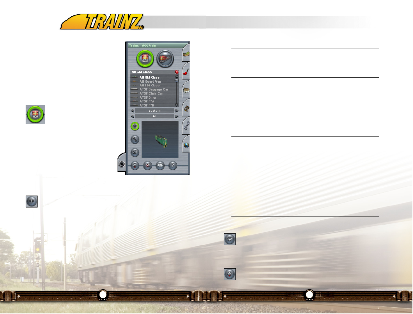
123
Tip: If there is a green checkmark with the letters "IND" shown in the
lower left corner of the Viewer window, this is an indication that this is
an "interactive" piece of rolling stock capable of participating with
"interactive" industries.
Tip: There is a little red button at the top right of the list labeled the
Favorites Toggle. If you click on this button, it turns Green and the list
will display only those engine and rolling stock assets that you flagged
as a Favorite using the Railyard module (described in the Engineers
Guide). This allows you to eliminate those assets in which you have
no interest making asset selection easier. Click LMB on the Favorites
Toggle button once more to view all assets.
Continue to select items to be added to your consist, Clicking LMB on one end
of the consist or the other to add engines or rolling stock. The Red and Green
arrows adjust to mark the ends of the consist. Note that if you Click LMB too
far away from the end of the consist, your addition will begin a new consist.
The Green arrow indicates in which direction the consist will move when
moved forward when operated in Driver.
Tip: If you want to move the consist that you are building to another
point on the track, use the Move Consist function available by
switching to Consist Mode (described below)
Rotate Train (R)
Click LMB on Rotate Train (R) to enable rotation of the engine or cars
in a consist. Once enabled, Click LMB on any engine or car in a consist
to change the direction in which it is facing.
Get Train (G)
Click LMB on Get Train (G) to enable you to quickly find a copy of an
engine or car already placed on the track. Once Get Train (G) is
selected, Click LMB on any car in any consist on the route and that car will be
122
11.11 Trains Menu (F7)
In TRS2006, you may assemble consists and
place them on track anywhere within the world
you have created in Surveyor. The Trains tab is
used for this purpose.
11.11.1 Building and Placing Trains
Train Mode (T)
Clicking LMB on the Train Mode (T)
button in this tab allows you to
assemble consists. A list of all
engines and rolling stock is displayed below
this button. Below the list are selection lists for
Train Origin and Train Company. If "All" is
selected in both of these lists, all consists and
rolling stock will be displayed. By selecting
a region or company in these lists the list
displayed can be restricted to just that
company or just that region or both.
Add Train (A)
Click on Add Train (A) to enable the building of a consist. Click LMB on
the engine or rolling stock asset in the list that you would like to place
on the route. Note that a picture of the asset appears in the Train Viewer
window in the bottom of the tab. If you Click LMB on the asset in the Train
Viewer window, the picture will rotate to show you different views of the
selected item. Click RMB+H on the item in the picture and move your mouse
forward and back to increase and decrease the size of the item in the Train
Viewer window.
Click on a location on a track in your route and your item will be placed at that
point.
Page 63
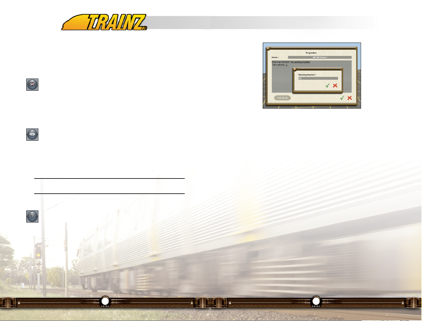
125
A name will be assigned to the engine or car by adding a number to its name
as found in the list of locos and cars. You may change the name to any unique
name that you wish. Names for locos and rolling stock persist only for this
particular session.
You may also change the running number for an engine or car by Clicking LMB
on the underlined text after the words Running Number. A new window opens
in which you may enter the number of your choice. If the engine or car has
been designed with a number that is changeable, the number will change to
match your selection.
124
selected from the list in the Trains tab and displayed in the Train Viewer
window. This makes it easy to find any engine or car if you wish to add more
of them to the route.
Delete Train (D)
Click LMB on Delete Train (D) to enable you to delete any engine or car
already placed on the track. Once Delete Train (D) is selected, Click
LMB on any engine or car in a consist on the route and that engine or car will
be deleted. The consist will shorten if necessary to close the space taken by
the car or engine and keep the consist intact.
Decouple Carriage (X)
Click LMB on Decouple Carriage (X) and then move the cursor to a
point near the connection between two items in a consist until an image
(colored Red) of a coupler appears. Click LMB on the coupler and it will be
seen to open. Additional Green and Red arrows will appear above the point of
uncoupling to mark off the two consists that have now been made from the one
original consist.
Note: To re-couple these consists or any two trains, use the Move
Train (M) button described a bit later.
Edit Properties (P)
Each engine or car in TRS2006 can be assigned properties. Click LMB
on Edit Properties (P) to enable the setting of properties for engines and
vehicles. Click LMB on an engine or car in a consist on the route and a new
Properties window opens up.
Page 64
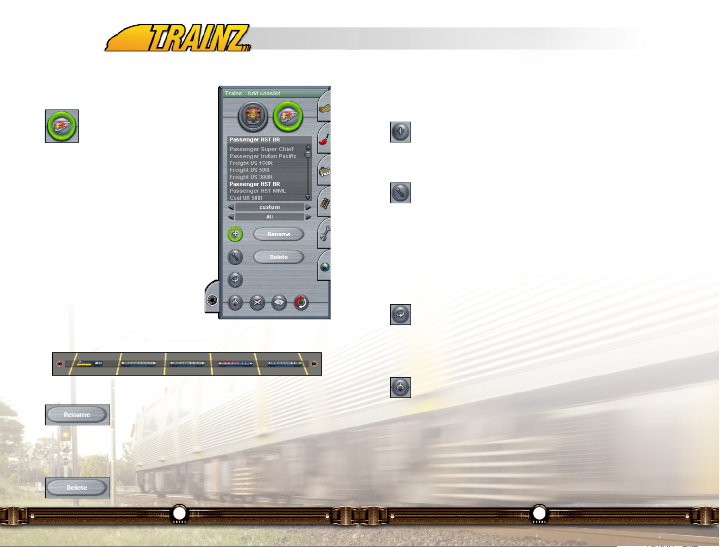
127
to delete the consist currently selected in the list. A window will open up in
which you will click on the Yes or No button to confirm or deny the deletion.
Add Consist (A)
Click LMB on Add Consist (A) to add one of your chosen consist to your
choice of points on the route. Click LMB at any point on the track to
place the complete consist there.
Move Consist (M)
Click LMB on Move Consist (M) to enable you to move any consist on
your route along the track to adjust its starting position. Click LMB+H on
any consist to move it back and forth along the track.
To join two separate consists together, move one consist along the track until
it touches the other consist then release LMB. The two sets of associated Red
and Green arrows that marked out the will then combine into one set for the
new consist.
Rotate Consist (R)
Click LMB on Rotate Consist (R) to enable the rotation of any consist
so that it is pointed in the other direction. Click LMB on the consist to
change its direction. The Red and Green arrows will also switch positions to
reflect the rotation.
Get Consist (G)
Click LMB on Get Consist (G) to enable the addition of newly built
consist to the consist list as well as the quick selection of copies of
consist already on the track from the list of consists. Then Click LMB on any
consist on the track.
If the consist is already in the consist list, it will be selected in that list so that
it is easy for you to add a copy of that consist to the route.
If the consist is not in the list (likely because you have assembled and placed
it previously in Train Mode, you may now give it a name in the window that
126
11.11.2 Train Management Tools
Consist Mode (C)
Click LMB on Consist Mode (C), one
of two large buttons at the top of the
tab, to enable the placing of
complete consists available in the list of
consists below the button.
A consist window appears at the bottom of the
screen which display the currently selected
consist in the list at the top of the tab.
Click LMB on any consist in the list and it will
appear in the consist window for your
reference.
You can Click LMB on any of the vehicles in
the consist window to change their
direction. Click LMB and hold on a vehicle
and drag it outside of the consist window to
remove it from the consist.
Rename Consist Template
Click LMB on the Rename Consist Template (large gray
colored button labeled "Rename" under the consist list)
button to rename the consist currently selected in the list. A window will open
up in which you may do the renaming.
Delete Consist Template
Click LMB on the Delete Consist Template (large grey
colored button labeled Delete under the consist list) button
Page 65

129
11.12 Surveyor Title Bar
The Title Bar appears at the top of the Surveyor screen and has several tools,
plus the Main Menu drop-down box.
The Title Bar is set to hide by default. Moving your mouse to the top of the
screen will display the Title Bar.
Quit (Esc)
The Quit button is not really part of the Title Bar as it is always there
regardless of whether the Title Bar is visible. However when visible, the
Quit button sits on top of the Title Bar.
Surveyor Main Menu
Clicking on the word Surveyor on the title bar opens up the
Main Menu drop-down box. Full details on these menu
options are listed in section 11.13.
Quick Drive (Ctrl-F2)
The Quick Driver button is shortcut that you can use to run the current
session in Driver. This can be handy for session creators who can jump
quickly into their session and test it without having to quit Surveyor.
Edit Session Rules
This button opens up the Edit Session window where the rules that
define a session are added and configured. See sections 11.13.7 and
11.14 for further details on this window.
Content Search Filter
Clicking on this button opens the Content Search Filter window which
you can use to define you own filters for use in the asset lists found
across the various tool menus such as Objects, Track and Trains.
128
opened up and the consist will be added to your list for future use. This is a
great way to build up a list of your favorite consists for use on many different
routes.
Tip: When you name a consist, that name persists in the consist
inventory across other routes and sessions where it is used.
Delete Consist (D)
Click LMB on the Delete Consist (D) button (not to be confused with the
big gray colored Delete Train Template button in the middle of the Tab)
to enable the deletion of consist placed on the track. Then Click LMB on any
consist to remove it
Decouple Vehicle (X)
Click LMB on the Decouple Carriage (X) button to enable the
decoupling of parts of a consist to break them up into smaller consists.
Then Click LMB on the coupler icon that will appear when you move the cursor
between cars or engines in a consist. You will see that the red and Green
arrows will show that you now have two consists. Use Move Consist (M) to
move them apart if you wish.
Change Heading (H)
Click LMB on the Change Heading (H) button to enable the changing of
the heading of a consist. Then Click LMB on any consist and the Green
and Red arrows will move to opposite ends of the consist setting the direction
that will be forward when the consist is started in Driver mode.
Page 66

131
When the name entry box appears, enter in a name for the filter and Click LMB
on the check icon. Close the Content Search Filter window be clicking on the
"X" in the top left corner and return to the main Surveyor screen. Open up the
Objects menu (F3) and select your filter. Click LMB to select your category and
note how the only assets in the object list are airport assets.
Undo (Ctrl-Z) and Redo (Ctrl-Y)
Undo and Redo are very useful functions for clearing up
mistakes and recovering deleted objects etc. The
number of levels you can undo or redo is determined by your computer
memory. To use, just click on the appropriate Icon and your last step is Undone
or Redone. If you have done a number of things quickly, such as painting a
number of textures, be aware that these may all be become undone in one
click.
Bookmarks
Bookmarks are used to set a location on your
map that you want to return to later. To set a
Bookmark, right click on the first Bookmark icon and notice that it changes to
a green color. This sets that bookmark at the point where the compass is
located.
Navigate to a new area on the map and Click RMB on the second bookmark
to set it to that location. To recall the first bookmark, Click LMB on the first
green icon. The map is re-centered to the original location.
You can also set and recall Bookmarks using Ctrl-1 through Ctrl-0 to set the
bookmarks and use keys "1" to "0" to recall them.
Wireframe View (F9)
The Wireframe View button (F9) replaces the textured terrain with a
see-through wireframe. This mode is useful for seeing what lies
beneath the ground such as under hills when placing and moving tunnels. Use
F9 again to return to the regular view.
130
To create a new search filter, select a Region and enter the Author and an Era
if desired (1980s, 1990s etc.). The main text field is keywords for the filter to
use when finding assets.
For the sake of an example, just enter the word "airport". To save this custom
filter, Click LMB on the text field next to the "Search Filters" field at the bottom
of the window. Scroll to the top of the pop-up list and Click LMB on the
"Save..." item.
Page 67

133
11.13 Surveyor Main Menu
There are additional functions in Surveyor that
are located in the Surveyor Main Menu at the
top of the screen. To open the Surveyor Main
Menu, Click LMB on the word Surveyor on the
main Title Bar. (If the Title Bar isn't visible,
move your mouse cursor to the top of the
screen and it will drop down).
11.13.1 Creating and Saving Routes &
Sessions
New Route
Click LMB on New Route to replace your existing route with a totally new
route. You will be asked to Save if you have made changes to the route that
you were working on. In the Create a New Route window that next opens up,
enter or select the following information:
132
Lock Menubar (F10)
You can lock the Menubar by toggling the Lock Menubar icon in the
upper left corner of the screen. If it is locked, the Menubar will always
be there for easy access. To hide the Menubar again, click again on the Lock
Menubar icon and move your mouse to the bottom of the screen and it will
disappear shortly.
Page 68
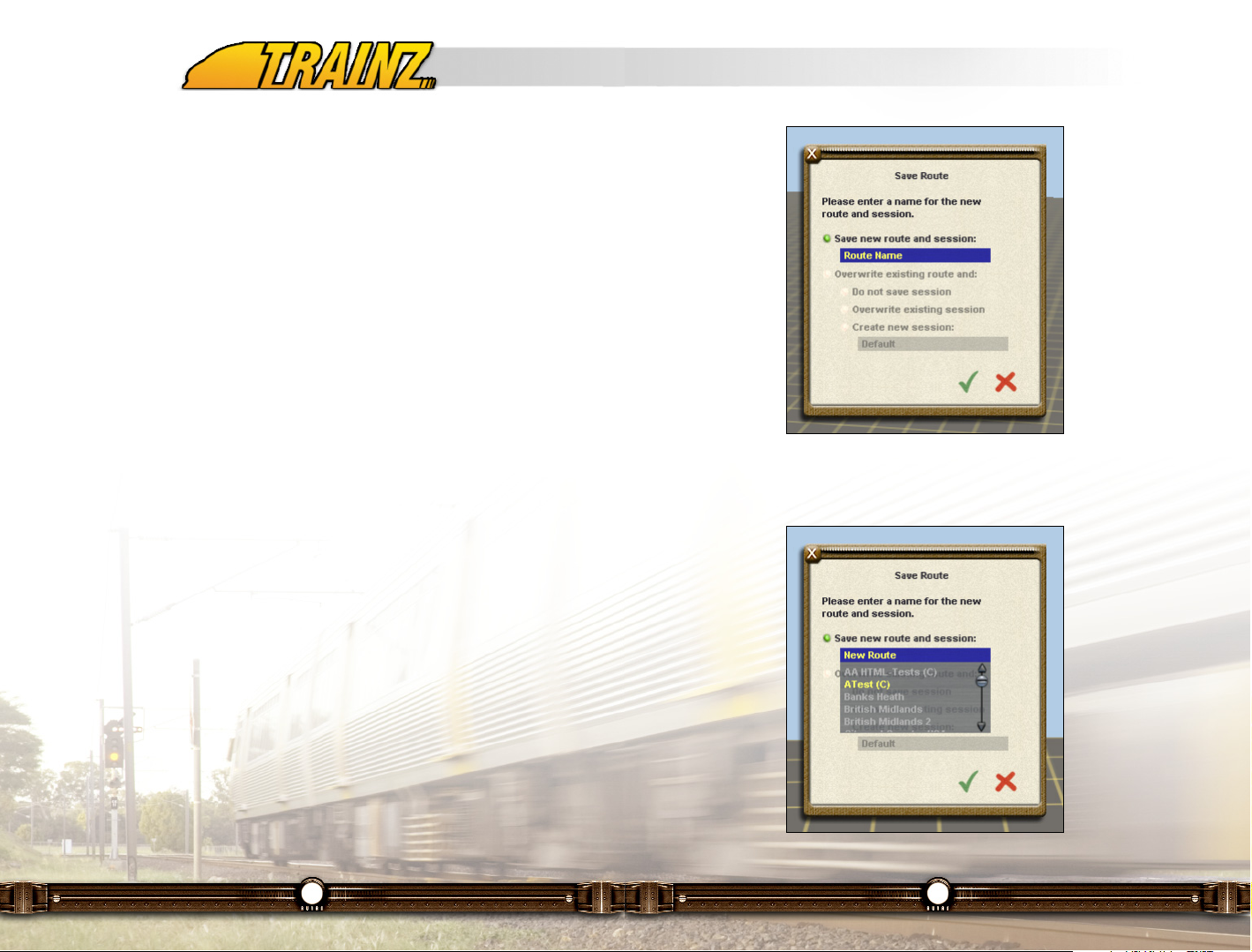
135
If you wish to save it with a new name, click on the name New Route and a
drop down menu appears as follows.
134
Give the new route a Route Name (replacing the name New Route and give
this instance of the route a Session Name as well. This allows you to have a
single route with multiple instances of it available. For example, you may have
different sets of trains in different sessions. The options are endless.
Select a Geographical Region from the list for your route. One impact of
selecting a region is that the cars will drive on the appropriate side of the road
for your region. It will also affect the default latitude and longitude settings for
the World Origin, the placing of Trackside objects and the default selection of
Metric or Imperial measures.
Set the Working Scale to Real Scale if you wish to develop a virtual railroad
rather than a scale model one. This setting affects the markings on rulers that
you can use to size things up on a route as you build it. If you select HO scale
instead for example, the rulers will measure distance in actual inches or
meters in HO scale. If you are developing a virtual version of a model railway
select the appropriate scale.
Set Working Units to metric or imperial measures as you wish. This will affect
the measurements used when displaying the operating conditions in the
engines as you are operating them.
Save and Save As
Use Save if you simply want to save the route and session that your are
working on with the same names that you saved them with last time.
Use Save As if you wish to save either the route or the session you have
created with new names.
In either case you will see one or more of the following menus appear
depending on where you are in the route and session building process. Note
that the buttons that the items that you select have green buttons. If you
cannot click on a red button to turn it green, it is because that option is not
available to you at this time.
Page 69

137
If this variation of the menu appears, you now must decide if you are going to
override the route and the session information or just the route information.
Click LMB on one of the buttons to the left of the following three options.
Do Not Save Session
This will save the route as you now have developed it but will not replace the
session information such as the trains placed on the route and the information
you have modified using the Edit Session menu item described below. This
allows you to save just the route that you are working on with the same name
as you loaded it with.
Overwrite Existing Session
This will save the route as you now have developed it and it will also replace
the session information such as the trains placed on the route and the
information you have modified using the Edit Session menu item described
below. The existing session information will be overwritten.
Create New Session
This will save route as you now have developed it. It will also create a new
136
You may now either type a name of your choice on top of the New Route name
or you can click on any of the names in the list below if they have a (c) beside
them. The (c) beside the name means that this is a route that has been
created earlier by yourself or is a downloaded route created by someone else.
The Names in dark black type such as "British Midlands" are routes that came
with the TRS2006 product and cannot be overwritten. So you have the option
of clicking on any of the routes with a (c) beside them if you wish to overwrite
them with the route you are working on now. If you do choose to overwrite a
route, you will see the following menu:
Click LMB on Yes or No depending on which choice you would like to make.
Tip: Be careful when overwriting a route as the route being overwritten
is erased forever. Some route builders chose to store successive
versions of a route with a different name or with a version number so
that they can recover a prior version if they wish.
WARNING: If you Save As and use the same name for the Route
you have just edited and Click LMB on the green tick you will get
a dialogue box appearing that asks if it is OK to overwrite the
route, If you Click LMB be aware that all dependent Sessions for
that Route will be lost. If you don't want to be in danger of losing
Sessions choose a different name for the Route. As the Routes
that come with TRS2006 cannot be overwritten, this warning does
not apply to Sessions dependent on these Routes.
Page 70

139
When this menu appears, you have the option of overwriting the existing
session information or creating a new session. Click LMB on the red button to
the left of Create a new session and enter a new session name by Clicking
LMB on the field below it and entering a new name. Note that a drop down list
of existing sessions appears. You may select one of these for overwriting if you
wish.
If you select Save or Save As and there have been no changes since the last
save operation, this message will appear. Click LMB on OK to return to
Surveyor.
11.13.2 Delete Missing Assets
Delete Missing Assets will remove any links to missing objects. This may have
occurred if you have downloaded a new map and don't have all the custom
138
session with information such as the trains placed on the route and the
information you have modified using the Edit Session menu item described
below. So now you will have a route with more than one session saved for it
as the Session you loaded the route with will continue to be saved as well with
the old name.
If you choose this option, enter a new name for your session in the field
provided.
Tip: One of the great features of TRS2006 is that you can save many
different operations session setups with a given route. E.g. an early
morning passenger run or a midnight freight haul.
If this menu appears, you may save the new route and session with the current
route name (New Route) or you can click on the field and enter a new name
for the route. The existing session (Default) will be stored with the new route.
Page 71

141
Whilst in mini-map mode, you can navigate around the terrain quickly by
zooming out and Clicking RMB to move the baseboards around the screen.
There is also the ability to show/hide certain types of items in the Mini-Map
view. Click LMB on the "Map Display Options" text in the top left corner of the
Mini-Map window and select/deselect the items you want to show/hide as
desired.
Click on the "X" in the upper left corner of the Mini-Map to close this window.
140
content installed, or have older content that is not compatible with your version
of TRS2006.
This menu will appear asking you to confirm or deny the action.
11.13.3 Mini-Map (Ctrl-M)
Click on Mini-Map to bring up an overview of your current map. Ctrl-M is a
quicker way of bringing up this map. You can also toggle the Mini-Map on and
off using Ctrl-M.
Page 72

143
11.13.5 Merge Route
Merge Route is an important tool for joining one saved route to another. Select
Merge Route and a list of all your saved maps are displayed.
Choose which map you would like to join to the current map from the list and
click on the Check Mark. You will see the baseboards from both maps and red
shading on the baseboards where the current map and the new map overlap.
142
11.13.4 Find Object (Ctrl-F)
Find Object (Ctrl-F) brings up a dialogue box that lets you type in the name of
an object. The map will be re-centered if any "named object" with that name is
found. An error is displayed if there is no object by that name.
Only certain objects can be named such as turnouts, signs and stations. By
selecting a type other than "All" you can narrow down your search.
Page 73

145
You may now change the Route name, add a Description, change the Working
scale and the Working Units (which were discussed above in section 11.13.1).
11.13.7 Edit Session
Click LMB on the Edit Session item to open up the Edit Session window. This
window is where sessions are constructed and configured using with rules. A
default minimal session with several basic rules is already provided.
Further details about this window and how it is used to construct a session can
be found in section 11.14 of this manual.
11.13.8 Performance Tuning Options (Ctrl-T)
One of the most important menu options in the Main Menu is the Performance
Tuning option (Ctrl-P). Here you can see how to adjust the settings to improve
performance depending on your PC specifications. In general, if your frame
rate is too slow then adjust the sliders towards the left. These setting are
discussed in more detail section 7.3 of this manual.
144
Use the four small arrows at the bottom of the box to move the map to be
merged left, right, up or down and use the four white arrows on the mini-map
to navigate around the mini map. Click LMB on Proceed once you have
uncovered all the red overlapping sections.
Tip: You cannot rotate a new map but you can join to it on any side.
Large maps will take some time to merge. Before merging, rotate the
camera so that you are facing North. This helps you understand which
side of your existing route you want to join to.
Once you have merged two maps, you will have to edit the joins to smooth out
different level terrain, and also to join track from the old section to the new.
You can change the map name, scale or measurement units using the Edit
Project dialogue box.
11.13.6 Edit Route
Click LMB on Edit Route and a window opens in which you can modify the
properties associated with a route. This is the same screen that appears when
you clicked on Create New on the Surveyor main menu.
Page 74

147
Select Panning as the default Camera Behavior and the map slides left or right
when you navigate around the terrain. Rotation means that the map will rotate
slightly as you navigate.
Fixed Track Vertex Height if set to On ensures that as you lay track, the spline
points are "fixed" at that height so that when you adjust the terrain height, the
track doesn't move. You can then use Smooth Spline to adjust the terrain and
Adjust Spline Height to move the spline points up or down.
With Spline Point Rotation set to Off you can turn the white circles from
spinning to static.
You can set the Function Keys Open Panels so that the Function Keys (F1,
etc) open the panels by turning this option On. If you set this option to OFF,
the Function Keys will enable that panel but will not open the panel. Once you
know all the hotkeys, this function can speed up your map making.
Use Randomly Rotate New Objects when you are placing forests etc. You may
want to switch it to Off when laying rows of houses.
Contextual Information determines the level of help graphics that displays in
Surveyor. Set it to Off and only the current Menu graphics are displayed. (e.g.
Track spline points won't display whilst the Texture Menu is open).
146
11.13.9 Surveyor Options (Ctrl-O)
The Surveyor Options menu (Ctrl-O) provides different default behaviors for
the TRS2006 interface. You can adjust the mouse scrolling speed and alter the
way the keys work.
If the mouse is moving too fast for you when you hold down the RMB, adjust
the Compass Speed slider to the left.
Select the keys option for Compass Movement to use the cursor keys for
moving the compass. The mouse will then move the camera.
Page 75

149
11.14 Session and Rules Management
11.14.1 Introduction
One of the powerful features of TRS2006 is the ability to apply Rules to a
Session. TRS2006 ships with some standard Rules to get you started, but like
other assets, new Rules will become available for download enabling you to
expand the possibilities.
What can rules do? Well they can set basic parameters in a Session including
which driver is in each Train, the weather state, control method, set up industry
dependencies, what Driver Commands are available in the Driver Module and
set the time and time rate.
They can also be combined, so that when a particular train hits a trigger the
weather may change or a sound may be played.
Then there is the ability to pull HTML pages and sound files into the game. On
top of that the Rules can be arranged to occur in a particular order.
All of this adds up to an open-ended system to manipulate the Driver
experience, even for someone who has no real programming experience. We
expect Rules to be one of the strongest features of TRS2006 as there really is
no limit to what can be done using Rules.
Note: If you don't want to have anything to do with Rules (Keep It
Simple) then fear not, a default set of rules including assigning Drivers
to Trains is automatically saved when you save a Session in Surveyor.
In this section we will describe how to use the Edit Session interface to add,
delete and edit rules. The rule themselves are a large complex topic with their
own document known as the "Session and Rules Guide" which is available
from the Trainz website.
148
11.13.10 Help System
There is also a Help option in the Main Menu. The Help text menu that
appears describes the various functions of each of the keys in Surveyor.
Page 76

151
11.14.4 Editing Rules
Each rule may have a number of parameters associated with it that need
configuring in order to modify it to your requirements. Highlight the Rule in the
list that you wish to modify and Click LMB on the "Edit" button to bring up the
Rule's Properties Window. All editable parameters are made available to
configure in this window. By clicking on the available hyperlinks, you can edit
the rule’s parameter.
150
11.14.2 Edit Session
Recall that a Session is different from a route as it may include for example
different trains. Click LMB on Edit Session on the Surveyor Menu and a
window opens in which you can modify the properties associated with a
Session. From here, you may change the Session Name, add a Description,
and the operating Rules to be used in this session.
11.14.3 Adding Rules
Click LMB on the Add Rule button (labeled "Add") to add a new rule to the
session. A window opens up with the set of rules that you can choose from.
Click on any one of the rules to add it to the list of rules to be included in this
session.
Once you have added the rules you want, it is time to edit them to make them
specific to your needs. See the individual descriptions of the major rules below
for guidelines on editing them.
Page 77

153
Note: The top level of the Rule Hierarchy is reached when the Rule is
lined up as far left as it can get (Further presses of the Outdent button
have no effect).
Indent (Rule)
To Indent a Rule by one level select the Rule by Click LMB to highlight
it and then Click LMB on the "Indent" button. This makes the selected
Rule dependent on the next higher Outdented Rule above it. The indented
Rule will not be executed unless the Rule next up in the Hierarchy is activated.
Promote (Rule)
To Promote a Rule up the Rule List select the Rule by Click LMB to
highlight it and then Click LMB on the "Promote" button. Once the Rule
has reached the top of the Rule list it can no longer be Promoted.
Demote (Rule)
To Demote a Rule down the Rule List select the Rule by Click LMB to
highlight it and then Click LMB on the "Promote" button. Once the Rule
has reached the bottom of the Rule list it can no longer be Demoted.
Delete (Rule)
If you want to remove a Rule from the list select it by Click LMB on it and then
Click LMB the "Delete" button. A dialogue box pops up confirming the deletion.
Click LMB the "Yes" button to confirm the deletion or Click LMB the "No" button
to cancel.
152
You can also edit the name of any Rule by Click LMB on it's text descriptor and
typing in its new name. This can help identify a particular Rule in a complex
Rule arrangement. Note that it is possible to have multiple rules of the same
type in a session where each rule instance has its own configuration.
11.14.5 Managing the Rules
The Rules in your Rules List can be further manipulated by the four command
buttons at the bottom of the Edit Session window.
The Outdent, Indent, Promote and Demote commands are used to order the
Rules in a Hierarchical and Ordered fashion.
Some rules (like the Trigger Check Rule) require indented child rules
immediately below them. This determines what happens when the Trigger
Check Rule is activated. Other rules, like the Ordered List Rule also use child
rules below them to fulfill its purpose. The child rules below the Ordered List
Rule can be re-ordered by using the "Promote" and "Demote" buttons to alter
the order in which they are executed.
As you can imagine the combinations are limitless.
You can also Delete Rules altogether by selecting the Rule with a Click LMB
and then Click LMB on the "Delete" button.
Outdent (Rule)
To Outdent a Rule by one level select the Rule by Click LMB to highlight
it and then Click LMB on the "Outdent" button. This removes the Rule
from dependency upon the Rule it was Indented under.
Note: Be careful here as Rules subsequent to the Outdented Rule that
are Indented will now only be executed if the Outdented Rule
conditions are met. Use the "Promote" and "Demote" buttons to reorder the Rule List if this is not the desired outcome.
Page 78

155
12.3 Launching the Driver Module
Click LMB on the TRS2006 icon on your desktop or start the TRS2006
program from the Start Programs function in Windows. You will then see the
loading screen with a randomly chosen TRS2006 hint and a rotating gear in
the bottom right corner that keeps rotating as Trainz loads.
Tip: The loading time will vary with the amount of custom content that
you download into the system. It will also take longer after you have
added custom content as TRS2006 then rebuilds its "cache" files to
include the new content.
The TRS2006 Main Menu then appears as shown below. There are four
modules to choose from: Surveyor, Driver, Railyard and Trainz Exchange.
154
12 - Engineer’s Guide
12.1 Introduction to the Driver Module
Driver is a lot more than just a driving simulation. First, you get to explore the
tracks from behind the throttle, from trackside as trains come thundering past,
from a bird's eye view tracking along with the trains or from a free-roaming
camera.
Then you can switch to an overview map and control all the junctions and
monitor signals and traffic flows. Running multiple consists, you can control
each train yourself, letting the computer AI system control the trains as you
control the switches.
You may also operate in accordance with the waybill system. This system
issues waybills for resources that need to be delivered to and from various
interactive industries in order to maintain the operation of these industries and
the railroad.
12.2 Entering Driver Directly from Surveyor (Ctrl-F2)
Before we explain how you normally launch a driver session in TRS2006, let
us alert you to a handy feature for those of you who will be building your new
or modified routes and sessions in Surveyor.
In the middle of your Surveyor construction session, you can now try out your
new route and session simply by hitting "Ctrl-F2". This will transfer you directly
into Driver. When you leave Driver mode, you will automatically return to
Surveyor so that you can continue to work on your route having tried it out.
This avoids your having to save your session and then exit Surveyor to load
your session into Driver.
Please note that on your way back from Driver, you will be asked if you wish
to save your session for reloading in future just as you might do in a regular
driver session.
Now, let's get on with the normal approach to launching into driving trains.
Page 79

157
contained in the Description window. Choose the Session you want to load
into Driver by clicking LMB on it, then Click LMB on the "Load" button at the
bottom of the screen.
To load a saved Driver session, Click LMB on the "Saved Session" button and
a screen loads which lists all of your saved Driver sessions. Click LMB on the
one you want to load to highlight it and then Click LMB the "Load" button at
the bottom of the Screen.
156
Click LMB on the button to the left of Driver to launch Driver (or press the "D"
key). The following Driver Main Menu now appears:
On the Driver main menu you will see a list of available Routes and Sessions.
When you Click LMB on a Session you can view the information (if any)
Page 80

159
12.5 Anatomy of the Driver Screen
12.5.1 Introduction
Let's take a look at the Driver Screen and where you can find the information
and controls you need. We're going to select one of the tutorials and use it
to demonstrate the common features of the Driver Screen.
At the Driver Main Menu select the "Tutorial 1 - Controls" session from the
"British Midlands 2" route. Load it by Clicking LMB on the "Load" button at
the bottom of the screen and it will begin to load the session.
The Tutorial 1 session does not have any train driving in it, but rather it is a
guided tour of the Driver module’s key interface components.
12.5.2 Driver Menu
At the top left of the screen is a drop down menu known as the Top Menu. It
only appears when the mouse pointer approaches the top left of the screen.
158
Click LMB on the Routes button to return back to the Driver Main Menu screen
with the route/session selection. Expand the list of sessions for the "British
Midlands 2" route. Select one of the two tutorials and then Click LMB on the
Load button on the bottom right corner of the screen. Trainz will load the
session for the chosen tutorial and you will find yourself outside a coal train
with an instructions window to guide you through the tutorial.
12.4 Tutorials + Manual = Fun
To help you get into the various activities available to you in the Driver mode
we have included six tutorials. They are:
• Tutorial 1 - Controls (British Midlands 2)
• Tutorial 2 - Waybills (British Midlands 2)
• Tutorial 3 - Diesel Cab (City and Country USA 2)
• Tutorial 4 - Steam (Outback Australia 2)
• Tutorial 5 - Drivers (Highland Valley Industries)
• Tutorial 6 - Commodities (City and Country USA 2)
Note: The tutorial sessions take place on several different routes and
won’t appear in order on the Driver Main Menu. To get to a tutorial, find
its corresponding route in the above list and expand that route in the
Driver Main Menu.
We will refer to each of these tutorials in the relevant section. You can use the
tutorials to get an "in-sim" handle on how to control your railroad, whether you
are driving a steam locomotive across the American Midwest, climbing the
Alps in a powerful electric locomotive or acting as a yardmaster in a busy
industrial belt route.
This section of the manual complements the tutorials by giving you "blow-byblow" descriptions of the controls and information you have at your command
while in the Driver module.
First though we will go through the common interface items to all Driver
sessions.
Page 81

161
12.5.5 Tool Panel
Finally on the bottom right is the Tool Panel. Here you'll find the waybill,
loading, uncoupling and map buttons.
12.5.6 Hiding the Interface (F5)
You can remove all the interface displays and panels from the view screen by
pressing the "F5" key. Pressing the "F5" key again re-displays the interface.
12.5.7 Screenshots ("Print Screen" or "PrtScr")
Want to do some virtual railroad photography? To take a "shot" of the screen
press the "Print Screen" key ("PrtSc" on some keyboards). The picture is
saved as a .TGA graphics file to your TRS2006 directory in the Screenshots
folder. Screenshots are stored in sequential order starting with the filename
"Screen_001.tga". The next screenshot will be saved as "Screen_002.tga"
and so on.
Use a graphics utility program to convert the TGA file to other file formats as
you require.
Tip: You can use the Hide the Interface (F5) toggle to maximize your
view of the action when taking screenshots.
12.5.8 Throwing Switches to Set Turnouts
Turnouts determine the direction your train will take. You can identify turnout
control switches by a transparent green/red arrow hovering over a red circle.
The green arrow indicates the direction the turnout is set to.
160
12.5.3 HUD Panels
At the top right of the screen are the Heads Up Display Panels. Depending on
whether you are in DCC or Cabin control mode it displays different information
relating to the currently selected train. It is also where you will find the camera
control panel, the train's current speed and the speed limit for the section of
track the train is on.
12.5.4 Driver Selection Panel
On the bottom left is the Driver Selection Panel. The picture at the bottom is
your currently selected Driver.
By clicking on the Driver’s picture, you can see a list other available drivers (up
to seven).
Page 82

163
In the Map View (see sections 9.3.5 and 12.8.4) you can also see the turnout
names and the directions they are set to.
You can Click LMB on them to change their direction. Signal states
immediately respond to reflect the change in turnout direction. This is very
useful for planning your train's movements as you can also observe the
location/movements of other consists and the location of industries.
12.5.9 Operating Turntables
Turntables are functional in TRS2006. To operate a turntable Click LMB on
one of the red curved arrows either side of the turntable platform to rotate the
turntable in that direction and line up with the next available track. The curved
red arrow turns green to indicate the turntable is moving.
162
If you have On Screen Help activated then the switch names and the turnout
direction will be visible at all times. If not you will need to move the mouse over
the turnout control switch to see its name and the turnout direction. The switch
controlling the turnout may be set back a little from the actual place where the
track meets, but will always be on the side where the two (or three) tracks
combine to form one track.
To change the turnout's direction all you need to do is Click LMB on the green
circle below the green/red arrow. The switch throws the turnout and the
green/red arrows change to reflect the turnout direction.
Note: If you are in the Cab View, hold the Ctrl key when you Click LMB
on the turnout switch.
There may also be three-way turnouts. In this case there are three arrows.
Two will be red and one will be green indicating the direction the turnout is set
to. Each Click LMB on the turnout controlling switch cycles through the three
directions: left, right or straight on.
You can also change the turnout direction of the next and previous turnout
relative to the currently selected Consist. Press the "J" key to switch the next
turnout or press "Ctrl J" to switch the previous turnout.
Page 83

165
1. The line may terminate or be closed, meaning a set of points or
turnout within the block it protects is set against it;
2. A part of a train may be occupying a part of the block it protects,
the signal shows red preventing any further traffic from entering
the block; or
3. A part of a train may be occupying a part of the adjacent block
when the signal will display Caution to indicate that the next signal
is at Stop
When a train encounters a green light, it is permissible to pass the signal at
normal speed. The signal will stay green until the rear of the train enters the
block, at which time it will change to red. Once the train leaves the block, i.e.
passes the next signal, the first signal will turn yellow, meaning it is safe to
proceed as far as the next signal which is now at stop.
During Driver sessions, any of the circumstances that result in a red or yellow
signal can be revealed. Move the mouse pointer over the signal lamp, and a
message will display the status of the block. Clicking on the signal lamp will
transport you to the obstacle whether it be a junction that needs switching, a
terminating line or another train.
Alternatively, your path can be cleared using the Map Screen overview, using
a simple dispatch simulation style display.
12.5.11 The Radio Message Box
The Radio Message box can be shown at the top of the Driver screen to alert
you to in game messages that may be of interest. To open the message box,
click LMB on the "Toggle new message" microphone icon located at the top
left of the Button Bar located in the bottom right corner of the screen. Click
LMB on the button again to close the Radio Message box.
164
Note: The turntable platform will line up with the next available track
at either end of the turntable platform.
12.5.10 Signaling System
The standard TRS2006 signaling system is based on an elementary controlled
block principle. The network is divided into blocks in both directions, all of
which are protected by signals.
Indications are as follows:
Green - Line Clear
The next signal is either green or yellow, proceed at normal speed.
Yellow - Caution
The next signal is red, proceed at low (half) speed.
Red - Stop
The block is occupied, terminates, or is closed.
All of the signals are red unless a train is approaching one, when it will turn
green to allow passage of the train. There are several reasons why a signal
may not be showing green in the presence of a train:
Page 84

167
Saved Driver Sessions are available to resume at a later time. Select "Saved
Sessions" when entering the Driver Module to see a list of saved sessions.
Click LMB on the required saved session and then Click LMB on the "Load"
button to resume where you left off.
Performance Settings (Ctrl-T)
Click LMB on this button or press the "Ctrl T" keys to bring up the
Performance Settings dialogue box. The sliders here adjust the
performance settings and gamma levels of the Driver module for this and
future sessions.
You can accept your changes by Click LMB on the green tick. To reset to the
default settings Click LMB on the "Reset" button or close the dialogue without
applying any changes to the performance settings by Click LMB on the red
cross.
See section 7.3 of this manual for descriptions of what the various
performance settings do.
Metric or Imperial Units (G)
Click LMB on this button or press the "G" key to toggle between metric
(speed in kph, pressure in kpa) and imperial (speed in mph, pressure in
psi). The default units are set in the Surveyor Module when saving the
166
12.6 The Driver Menu Bar
12.6.1 Introduction
The Driver Menu Bar is a drop down menu that appears when you move the
mouse cursor to the top left of the screen. When it has fully appeared the
buttons on it become active.
Exit Driver (Esc)
Click LMB on this button or press the "Esc" key to exit this Driver
Session. A window pops up giving you the option to "Save" your current
Session in its current state, "Exit" without saving or you can "Cancel" your exit
command.
Saved Driver Sessions are available to resume at a later time. Select "Saved
Sessions" when entering the Driver Module to see a list of saved session.
Click LMB on the required saved session and then Click LMB on the "Load"
button to resume where you left off.
Pause Session (P)
Click LMB on this button or press the 'P' key to pause your current
session. The "Pause" button will be highlighted indicating the session is
paused. The session will resume and the "Pause" button loses its highlight
when you Click LMB on the "Pause" button or press the 'P' key a second time.
Save Session (Ctrl-S)
Click LMB on this button or press the 'Ctrl S' keys. A window pops up
giving you the option to save your current Session in its current state
under a name of your choice. If you don't want to save the session, cancel by
Click LMB the red cross. Clicking on the green tick will save the session. If that
name already exists you will be given the option to overwrite the existing file
or cancel the save.
Page 85

169
Click on the name of the object in the "Object" list that you wish to view. Use
the scroll bar at the right of the "Object" list if it spans more than can be viewed
in the list window.
Click LMB on the red "X" to cancel what you are doing or Click LMB on the
Green Check Mark to move the camera focus to the highlighted Object. You
will automatically be in the Free-Roaming Camera mode.
On Screen Help (Ctrl-H)
Click LMB on this button or press the "Ctrl H" keys to toggle between
activating/deactivating the On Screen Help. The "On Screen Help"
button will be highlighted if this option is active.
When active, On Screen Help will show the names and direction of all turnout
control switches. You can identify turnout control switches in the view screen
by a transparent green/red arrow hovering over a red circle. The green arrow
shows the direction the turnout control switch is set to.
When On Screen Help is deactivated you need to move your mouse cursor
over a turnout control switch to see its name and the direction the turnout is
set to.
Note: In Cab View (internal) the mouse over trick doesn't work when
the On Screen Help is de-activated. If you want to check the status of
an up-coming turnout control switch, activate the On Screen Help
(button or "Ctrl H").
12.7 View the World - The Camera
12.7.1 Introduction to Looking Around
Let's take a look at the various views that are available to you whilst in the
Driver module. Get a clear view of the Driver Screen. Then you will be ready
to try out the various camera views available to you. Take a moment to get
familiar with these view controls, some time spent doing this will maximize
your enjoyment in Driver.
168
Session. If you are not happy with the default units, go into the Surveyor
module, change the units and save the session.
Find Object (Ctrl-F)
Click LMB on this button or press the "Ctrl-F" keys to open up the Find
Object window.
To filter the objects listed in the "Objects" list Click LMB on either of the buttons
at the end of the displayed line labeled "Type" to select which class of object
to show in the "Object" list. Selecting "All" will show all of the available objects
(this is default). You can also select the object type by Click LMB on the "Type"
text box to see a drop down list of all object types and then Click LMB on the
object type of interest.
Page 86

171
To zoom in and out use the mouse wheel or the "Page Up" or "Page Down"
keys.
When in Cab View in Cabin Control mode you can manipulate the train
controls directly with the mouse, or watch them move as you use the
keyboard. There may also be secondary animations…things like a window you
can open/close or a seat you can raise and lower. Why not explore a little with
the mouse and see what you can manipulate?
Note: Some locomotives use "generic" cabs so in Cab View their cabs
and control layouts appear the same. However, many locomotives
have unique cabs and hence different control layouts.
In Dual Cab locos, pressing the "Alt-C" keys will change the camera to the
other cab.
Note: Some rolling stock have had internal views activated. Choose
the rolling stock of interest by Click LMB on it and then select the
internal camera. In some cases you can also press the "[" and "]" keys
to different viewpoints inside/outside the rolling stock.
12.7.3 The External View Camera (2)
The External View Camera mode is selected by default when you
enter Driver with the focus point of the camera on the front car or
loco of the selected consist. You can select External View Camera
by clicking on the External View button on the Camera Panel or by pressing
the "Keypad-2" key.
To look at your focus point from different angles, Click RMB+H and moving
your mouse or press the cursor keys on the keyboard.
If you want to zoom in and out use the mouse wheel or the "Page Up" or "Page
Down" keys.
170
The camera views are also reviewed during the DCC tutorial.
There are four camera views in TRS2006 and the Map view. You are free to
move between them at any time to make the most of your Driver experience,
although there will be times when it's advantageous to focus on a view to
accomplish a particular action.
The four Camera Mode buttons are on panel on the HUD at the top right of the
screen.
We suggest you also review the Map View topic under the Tool Menu section
as the Map View is also an integral part of viewing, controlling and getting
around your railroad.
12.7.2 Cab View - The Internal Camera (1)
To go inside the Cab, click on Cab View button on the Camera
Mode Panel or press "1".
Note: If you do not end up inside the cab, you have probably not
selected the locomotive. Click LMB on the locomotive and try again.
Look around the internal view by clicking RMB+H and moving your
mouse or pressing the cursor keys on the keyboard. The left, right, up
and down movements emulates the movement of your head pivoting
on your neck.
You can also move to different internal cameras by using the "[" and "]" keys.
Depending on the locomotive the view may move around inside the cab, onto
the running boards or even outside the locomotive. These keys will move you
smoothly through the available camera views each time you press them.
Holding down the Ctrl key whilst using "[" and "]" will snap the camera to the
next position.
Page 87

173
RMB+H and then moving the mouse the view will track the cursor. The further
the cursor is pushed to the edges of the screen the faster the scene travels to
catch up. By moving the cursor while Click RMB+H to the corners of the
screen the view will rotate to follow. You may also use the cursor keys in
conjunction with the mouse control of the view to frame the scene as you see
fit. Don't forget you can also use the mouse wheel or the "Page Up" or "Page
Down" keys to zoom in and out.
12.7.6 Finding and Viewing any Object (Ctrl-F)
To take the Free-Roaming Camera to a specific object, move your
cursor to the top left of the screen causing the Top Menu to appear. The
second button from the right of this menu is a "Find Object" button. Click LMB
on "Find Object" to open up the Find Object menu. Click LMB on either of the
button at the end of the displayed line labeled "Type" to select which class of
object to show in the list. Selecting "All" will show all of the available objects.
Click on the object in the list that you wish to view using the scroll bar at the
right of the list if it spans more than can be viewed in the list window.
Click LMB on the red "X" to cancel what you are doing or Click LMB on the
Green Check Mark to move the camera focus to the highlighted Object. Once
there, you may use the free-roaming camera to roam the area at will.
Use of the find functionality is discussed further in section 12.6.1.
12.8 The Tool Panel
The Tool Panel is located in the bottom right corner of the Driver screen and
contains several buttons that provide access to various miscellaneous tools in
Driver and are discussed in the sections that follow.
172
To change the focus point Click LMB on any of the cars or move the view from
car to car sequentially by pressing the "-" and "+" keys.
You can also change your focus point to another consist by Clicking LMB on
it directly, via the MiniMap view (see Section 12.8.4) or by selecting a different
train from the Driver Selection Panel (see Section 12.5.4).
12.7.4 The Tracking View Camera (3)
The Tracking View Camera Mode is selected by clicking on
Tracking View on the Camera Panel or by pressing the "3" key.
Note: If you don't move to tracking view that is because there is no
tracking camera nearby as described below.
This view requires the placement of cameras within the layout itself (using the
camera tools in the Surveyor module as described in section 11.9.2). In the
Driver module, when you select Tracking View, the camera view switches to
the nearest camera to the currently selected train if and only if there is a
camera in range of the train. These cameras are stationary fixtures in the route
you have selected. Upon detecting your locomotive approaching, they become
active. The Tracking Camera turns or pans appropriately to follow your consist
as it passes and until the consist is out of range, whereupon the default
External View Camera is automatically activated if another Tracking Camera
can not pick it up. Not all layouts will be partially or completely equipped with
Tracking Cameras but you can if you wish add them in the Surveyor module
to an existing layout as well as a new one.
12.7.5 The Free-Roaming Camera (4)
The Free Roaming Camera is not connected to any given train it
works like the view controls in the Surveyor Module. Click LMB on
the Free Roaming Camera button or press the "4" key to enter this
camera mode.
Click RMB and the scene will move smoothly to centre on the cursor. By Click
Page 88

175
12.8.2 Commodities Panel - Which Carries What?
The Commodities Panel is accessed by clicking on this button. The
Commodities Panel is used to assign commodities to specific rolling
stock.
Assigning Commodities to Vehicles
A list of available commodities for this route is depicted as icons on the panel.
Click LMB on the required commodity and then Click LMB on the piece of
rolling stock in the view screen you want to carry that particular commodity.
The rolling stock selected must be capable of carrying the commodity you
have selected. You will know this is the case as when you move the cursor
over the rolling stock the commodity icon will appear. Click LMB to assign that
commodity to the car.
You can move the commodity panel by LMB+H and dragging it around and
dropping it so it gives you a clearer view of the available rolling stock.
Some cars may carry a variety of commodities. For example the "Oily Rag"
tank car can be assigned to carry only diesel, petroleum or crude oil. The
variety of commodities that a car is capable of carrying is determined by the
content creator when they create the asset. The commodities available to be
assigned to a valid piece of rolling stock are determined by the industries that
are placed on the route for the session you have selected.
Note: Only rolling stock that is "active" may be assigned to a
commodity. Some older pieces of "non-active" content are not capable
of carrying commodities.
174
12.8.1 Waybills - Who Needs What?
Waybills are automatically created by the active industries on the
session you have selected. In the session "Tutorial 2 - Waybills", the
Radcliff Power Plant has generated a waybill for coal.
Click LMB on the Waybill button on the Tool Panel in the bottom left of the
screen to bring up the Waybill window in which outstanding waybills governing
the operation of the session are listed.
The icons of the industries with active Waybills that need filling are listed on
the left of the Waybill window. If there are lots of them you may need to scroll
using the scrollbar. Click LMB on the industry icon to bring up its waybill on the
right panel of the Waybill window.
As you fulfill the listed industry's waybill by moving the relevant product to that
industry they are removed from the Waybill window…job done!
Of course industries continually consume resources so as they run low on
resources they will generate new waybills…so keep an eye on the Waybill
window for new jobs to appear.
To close the Waybill Window Click LMB on the "X" button at the upper left of
the Waybill Window. Clicking the Waybill Icon
Page 89

177
Commodities Tutorial
Before you run the tutorial that looks at Commodities we suggest you
complete and are familiar with the DCC and Driver Commands portions of this
manual.
To go through an in-game tutorial on the aspects of commodities discussed
above go to the Driver main menu and Click LMB on the "5 Commodity
Tutorial" Session for the City and Country USA 2 Route. Then click LMB on
the Green Light labeled "Load" in the lower right hand corner of the screen.
The program loads in the route and session information for the tutorial and the
session will start.
12.8.3 Decoupling
Being able to make up and break up consists is a classic operational feature
of the world of railroading. Decoupling is key to this.
Decouple Mode (Ctrl-D)
Click LMB on the Decouple button or press the "Ctrl D" key to
activate decouple mode. The button will light up to indicate that you
are in this mode. A Radio Message window pops up indicating you
176
There are two other icons that appear on the Commodity Panel.
Stop Icon
The first icon is the "Stop" icon. By selecting this icon with a Click
LMB and then Click LMB on a piece of rolling stock it makes the
selected car inactive. It will not load or unload any commodities even
if presented to a valid load or unloading track and issued a Load or Unload
command.
Default Icon
The second is the "Default" icon. By selecting this icon with a Click
LMB and then Click LMB on a piece of rolling stock you are returning
it to its default state. The default state allows the car to pick up any
compatible commodity. Going back to the "Oily Rag" tank car, if it is set as
default it can pick up and carry any liquid commodity (petroleum, crude oil or
diesel). However it still would not be able to pick up and carry a 20ft container
or lumber for example as these are not valid loads for this car.
When you have finished assigning commodities to rolling stock, you can close
the Commodities Panel by Click LMB on the "X" at the top left of the panel.
Note: All rolling stock starts off in the "Default" state for the purpose of
carrying commodities.
Commodity Levels in a Vehicle
To check a car's current state Click RMB on the car and select View Details
from the pop up menu with a Click LMB. An information dialogue box will pop
up describing the list of commodities the car can carry and how much (if any)
of each commodity is loaded. Click LMB on the "X" at the top left of the window
to close.
Page 90

179
current terrain. The map shows the position, length and driver (if present) of
each consist, signal states, the direction of each turnout (green/red arrows)
and important names such as industries, turnouts, trigger points and stations.
Zoom in and out using the "Page Up" and "Page Down" keys, the mouse
wheel or by LMB on the zoom in and zoom out magnifying glass icons above
the Tool Panel at the bottom right of the screen.
The map follows the movement of the currently selected consist. The currently
selected consist shows as green and all other consists show as gray on the
map. Click LMB on one of the gray consists to select that consist, centering
the map view on that consist in the process. The map will then move to follow
it.
Click RMB any point in the map to center the map view to a new location. You
will lose focus on the current consist. The map is now stationary (it stops
following the selected consist) and under your control. You can Click LMB on
the up, down, left and right arrows to scroll the map. Click LMB on any consist
to have the map resume following it.
You can also throw the switch levers on turnouts by Click LMB on the turnout
(green/red arrows). The green/red arrows will toggle and any changes to
178
are in decouple mode. Now move your cursor over the couplers between train
cars you want to decouple until you see a red decouple icon.
When the red decouple icon appears, Click LMB to decouple the consist at this
point. When you have successfully performed the decouple operation, the red
coupler icon "opens" and the Radio Message updates to announce a
successful uncoupling.
The act of decoupling creates a new consist and your camera remains
focused on the same car or locomotive as before the decoupling operation.
To re-couple, ensure that you are operating at speeds below 5mph (8kph).
Experiment with different camera positions to make this task easier.
12.8.4 Breaking Out the Maps - Where are We?
Without a map, it is easy to get lost. TRS2006 provides maps of each and
every route to help us find our way.
Map Screen (M)
The second icon on the Tool panel at the bottom right of the screen
activates the Map Screen (M). Click LMB on the Map button to the
left of the de-couple button to switch to a full screen Map View of the
Page 91
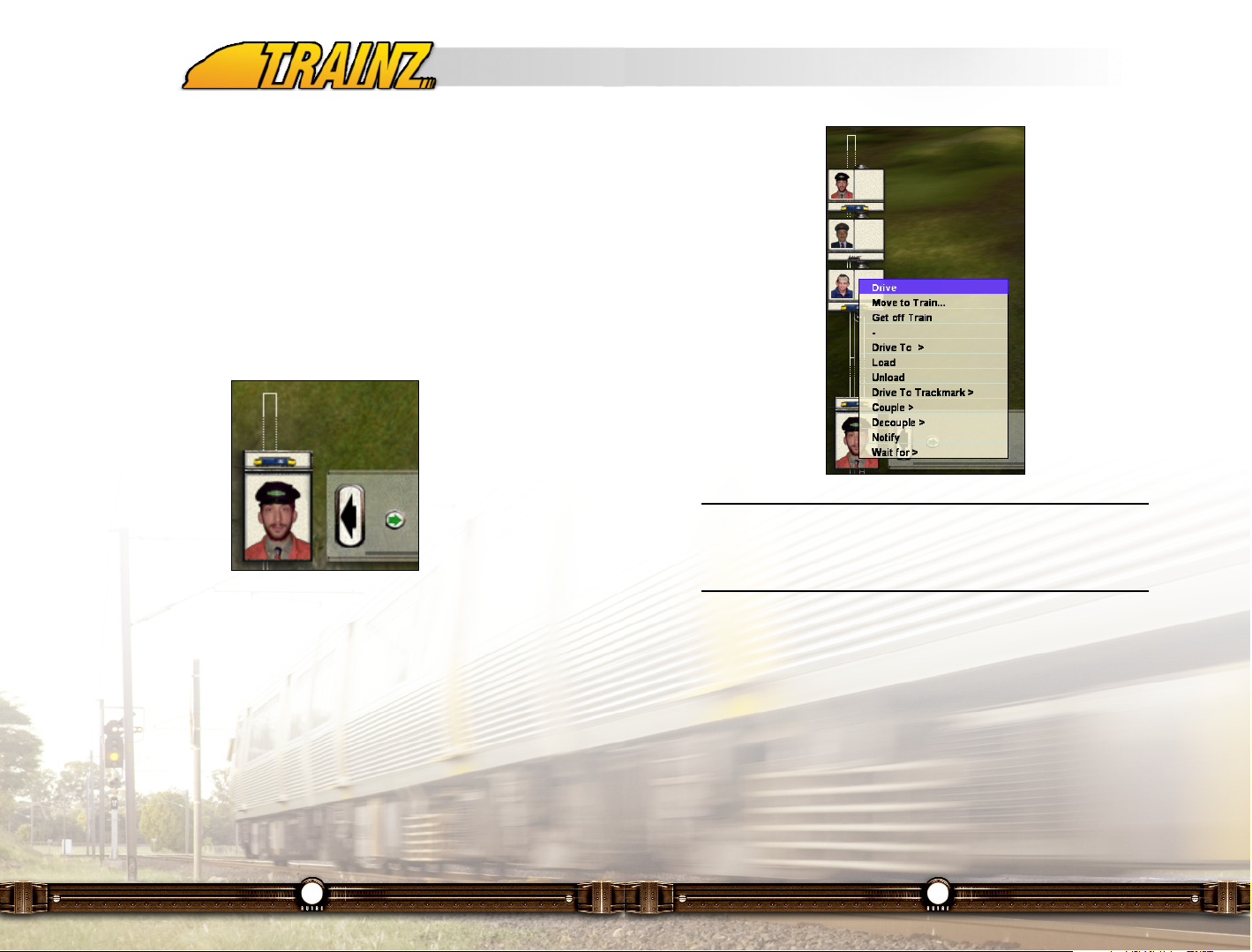
181
Note: If a Driver is not currently assigned to a locomotive there will not
be a locomotive icon under their portrait. This means this Driver is
available to be assigned to an available locomotive (see Section 9.4
on Driver Commands for how to do this).
You may select other Drivers by Clicking LMB on the handle above the
selected Driver picture. A complete iconized list of the Drivers available (a
Session can have up to seven Drivers). Along with the Driver's picture you will
also see their assigned locomotive and active Driver Command icon. Click
LMB on the Driver you want to select from the list and that Driver and his Train
are shown in the Driver screen and their picture moves to the currently
selected Driver slot.
You can also select a Driver from the keyboard moving them to the currently
selected Driver slot and making their train the focus of the Driver screen slot
by pressing the "Ctrl-#" keys where the # is the number of the Driver.
180
signal states will also occur on the map. This is very useful for planning your
train's movements as you can also observe the location/movements of other
consists and the location of industries.
Exit the map screen by Clicking LMB again on the Map Screen button, or
press the 'M' key.
12.9 The Driver Selection Panel
By default the Driver Selection Panel shows a picture of the Driver of the
currently selected Train along with a miniature icon of the locomotive they are
driving. If a Driverless train is selected a white box with a "?" is shown in the
picture frame.
To the right of the Driver picture are the sequence of Driver Command icons
assigned to that Driver by Click RMB on the Driver's picture you can add more
Driver Commands (see Section 12.12 on Driver Commands for more
information).
Page 92

183
consist. You are ready to roll…
Go through the tutorial to get a feel for the DCC mode. If you are not already
familar with the basic controls, play through the first tutorial "Tutorial 1 Controls" before attempting this one.
Below we look at each of the aspects of the DCC mode of operation, so use
it as a reference if you get lost during the tutorial.
12.10.3 DCC Control and Driver HUD
The information displayed in the HUD (Head Up Display) is dependent on the
Driving Mode selected in the Driver Settings menu. When in DCC mode, the
DCC Panel as shown below appears at the right side of the screen.
The DCC Panel consists of a throttle knob and four buttons which are
discussed in the sections that follow.
Note: If the currently selected train has Driver Commands in progress
the DCC Control Panel on the HUD is no longer visible and the train
is not manually controllable. To regain manual control Click RMB on
the driver and select "Abandon Schedule" or "Stop Train" from the
pop-up Driver Command Menu. See Section 12.12 for more
information on Driver Commands.
Tip: The DCC Control Panel and the Camera Panel can be
shown/hidden by pressing the "F9" key. This can also be a reason why
the DCC Panel is not visible.
182
While the Driver List is visible you can Click RMB on their icon to bring up the
Driver Command Menu for that Driver. You can then select what you want that
Driver to do from the list of Driver Commands (see Section 12.12 for more
information on Driver Commands). You can do this without changing the
currently selected Driver/Train.
To close the Driver list Click LMB on the handle at the top of the list and it will
slide down and disappear.
Now you know the basics of the Driver Screen layout and how to view your
world you can start on a tutorial to actually do something in Driver.
12.10 DCC Diesel / Electric / Steam Mode
12.10.1 Introduction
We've grouped all the locomotive types (diesel, electric and steam) together,
because in DCC Mode the control mechanisms are the same for all of them.
Think of DCC Mode as equivalent to a high cost Digital Command Controller
with momentum and braking effects. It's easy to use and quickly gets you
moving your train(s) around the route. As in most places in TRS2006 you can
use the mouse and/or keyboard commands to control the simulation.
12.10.2 The DCC tutorial
Go to the Driver Main Menu and Click LMB on the "Tutorial 2 - Waybills"
Session for the British Midlands 2 Route. Then click LMB on the Green Light
labeled "Load" in the lower right hand corner of the screen. The program loads
in the route and session information for the tutorial and the session will start.
An introduction to the tutorial comes up as a window and describes what you
will be doing in this tutorial - other windows will pop-up along the way to
explain aspects of the tutorial and help you achieve the tutorial goals. Click
LMB on the checkmark in the lower right corner of these windows to proceed.
Once you have read through the introductory screens you will see a stationary
British Railway Class 37 diesel locomotive hitched up to an empty car coal
Page 93

185
Pantographs (Keypad 1)
Lastly, if your locomotive has pantographs, click on the "Pantograph"
button on the right of the throttle control to raise and lower them or
press the "Keypad 1" key. If the locomotive has multiple pantographs
subsequent key/button presses will raise them individually or together before
cycling back to all down.
Speed Limit and Current Speed
Your current speed and the track speed limits are shown at the top of the HUD
above the Camera selection panel. You can toggle the units between metric
and imperial by either selecting the "Units" button on the drop down Top Menu
or pressing the "G" key.
You will need to check your current speed regularly against the track speed
limit and signal indications to make sure you operate the train safely.
12.11 Driver Commands and Working with Industries
12.11.1 Introduction
Driver Commands add a whole new world to TRS2006, allowing you to control
a railroad, not just a train. When coupled with Interactive Industries, active
rolling stock and Waybills this aspect of the Driver Module really will bring your
railroad to life.
12.11.2 Operations, Industry and Driver Commands Tutorial
Go to the Driver main menu and Click LMB on the "Tutorial 5 - Drivers" session
for the Highland Valley Industries route. Then click LMB on the Green Light
labeled "Load" in the lower right hand corner of the screen. The program loads
in the route and session information for the tutorial and the session will start.
An introduction to the tutorial comes up as a window and describes what you
184
DCC Throttle Control (W/X/S)
In DCC mode, a simple rotary dial controller is available
below the Camera Selection Panel on the HUD. This dial
controls the movement of the currently selected train and is
analogous to a model railroad DCC controller knob. Click
LMB+H on the dial and drag it clockwise to move forward.
The top central position of the dial is the stopped location. Dragging the dial
anti-clockwise will make it move in reverse.
Stop (S)
To quickly reset the dial and bring the current consist to a halt, click
on the "Stop" button or press "S".
You can also use the "W" and "X" keys for reverse or forward controls and "S"
key for stop. If you are using the keyboard to control the throttle you can refer
to the position of the rotary dial on the HUD to see your current throttle setting.
Handbrake (A)
The "A" key can be used as a handbrake to rapidly stop the train or to stop
loose wagons from rolling away.
Lights (L)
Activate the headlights by clicking on the "Light" button to the right
of the throttle control or pressing the "L" key.
Horn (H)
Press 'H' to operate the horn or click on the "Horn" button to the right
of the throttle control in the HUD. For long blasts of the horn, simply
hold the 'H' key down or Click LMB+H on the "Horn" button. Some
multi-tone horns only have a single blast pattern.
Bell (B)
Toggle the Bell on or off by pressing the 'B' key.
Page 94

187
Commodities
An Interactive Industry can produce commodities, it can consume them or it
can do both.
An example of an Interactive Industry that only consumes commodities is the
Power Station. It consumes Coal.
An example of an Interactive Industry that only produces a commodity is the
Forestry industry. It produces Logs
An example of an Interactive Industry that both consumes and produces is the
Lumber Mill. It consumes Logs and produces Lumber and Wood Chips.
Below is a flow chart of the Interactive Industries (in rectangular boxes) and
the Commodities (in rounded boxes) included in TRS2006.
Tip: Further industries and commodities are available form 3rd Party
Content Creators via the Download Station.
186
will be doing in this tutorial - other windows will pop-up along the way to
explain aspects of the tutorial and help you achieve the tutorial goals. Click
LMB on the green checkmark at the bottom right corner of these pop-up
window to proceed. The red arrows in the bottom left allow you to navigate
back to pages you have already seen if needed.
Once you have read through the introductory screens you will see a stationary
CN diesel locomotive. You are ready to roll…
Go through the tutorial to get a feel for bringing your railroad to life working
with interactive industries, operating turntables, coupling/de-coupling and
utilizing the power of Driver Commands.
Below we look at each of the aspects of the Driver Commands so use it as a
reference if you get lost during the tutorial.
12.11.3 Interactive Industries
Interactive Industries are scenery objects that produce/consume commodities
that are transported by rail. Your job is to get the right train with the right rolling
stock to the right industry for loading and then to move the commodities to the
right industry that consumes it.
Sound easy? Read on!
Page 95

189
Note: As new content is developed by the community we expect new
Commodities, Interactive Industries and Active Rolling Stock to
become available. The possibilities are endless with the open
architecture we have implemented in TRS2006. If you are interested
in creating your own Interactive Industry, Commodity or Active Rolling
Stock, please refer to the User Asset Creation Guide available from
the Trainz Launcher menu under Manuals.
Waybills
To help you out we've put in a waybill system that will tell you which Interactive
Industry requires what quantity of which Commodity. See section 12.8.1 on
Waybills to learn more about the Waybill system in TRS2006.
Industry Details
You can also get the details of what Commodity each Interactive Industry is
producing and how much so you'll know where to source Commodities to
complete your railroad's Waybill requirements. Click RMB on an Interactive
Industry to bring up a pop up menu. Click LMB on View Details to bring up a
window which describes the details of the type and quantity of each
commodity produced by that Industry.
188
Active Rolling Stock
You also need to use the right rolling stock to move commodities around the
railroad. Older rolling stock, including some of the rolling stock included with
TRS2006 is not able to carry commodities, let's call them non-active rolling
stock. Of course TRS2006 also includes examples of rolling stock that are
capable of transporting Commodities, we'll call these active rolling stock.
Note: In the Surveyor Module active rolling stock and Interactive
Industries are denoted by a "Tick" in their 3D preview window. See
Chapter 11 - Sureveyor In Depth for details.
Active rolling stock may also have animations associated with them, so you
will see the wood chips being loaded or the panels on the hoppers open as the
coal is unloaded.
To find out the status of a piece of active rolling stock Click RMB on the rolling
stock and select View Details from the pop up menu.
See section 12.8.2 on Assigning Commodities to learn more about the
flexibility of the new active rolling stock and how to assign the match active
rolling stock to the appropriate commodity.
Page 96

191
Note: Some load/unload tracks may require the train to be fully
stationary for a length of time (eg: container car) while others will allow
loading/unloading "on the fly" (eg: coal car).
Special Industry - The Steam Filling Station
Because of their fuel capacity diesel locomotive fuel consumption is not
modeled in TRS2006. Similarly electric locomotives are also considered to
have infinite fuel (unless someone scripts a Rule that makes them dependent
on the Power Station operating!).
However the same cannot be said for Steam locomotives. From time to time
they will need to have their coal/oil and water replenished. Included with
TRS2006 is a Steam Filling Station that provides a steam locomotive with its
coal/oil and water requirements.
Treat the steam locomotive like a mini-industry that consumes coal/oil and
water. Check on its current stockpile of these Commodities by Click RMB on
the locomotive tender (or the locomotive if it does not have a tender) and Click
LMB on View Details. If they are running low you'll need to get the locomotive
to the Steam Filling Station to top up.
Note: Steam locomotives use coal/oil and water in both the DCC and
Cabin control modes.
190
Some Interactive Industries also have one or more visual cues as to their
Commodity status. For example, the Coal Mine has piles of Coal that rise and
fall depending on production and Train loading respectively.
Note: The Power Station Industry details also indicate if the Power
Station is operating. This is important to know as a Power Station Rule
may be operating (see the World Builder Guide for more information
on Rules) which means other Interactive Industries are dependent on
the Power Station for electricity. No electricity, no production!
Loading and Unloading
Each Interactive Industry will have loading and/or unloading tracks depending
on whether it is a Commodity consumer, producer or both. These track
locations vary depending on industry, they are usually obvious or they may be
sign-posted. Some industries may load/unload different Commodities on
specific tracks, others use the same track for everything.
Note: Some Interactive Industries have loading/unloading animation.
To successfully load/unload you will need to be at the right track, with the right
piece of active rolling stock and traveling at the right speed.
Page 97

193
Note: The Driver Commands available to a Driver are updated
continuously depending on the current activity the Driver is performing
and the Driver Commands activated for this Session (set in the
Surveyor Module).
Driver Commands are listed in the order they will be performed as icons along
the bottom of the screen to the right of the currently selected Driver. This
sequence of Driver Commands is known as a Schedule. As each command is
completed it is removed from the Schedule and the next command is
executed.
Note: If the Repeat Schedule command is added to the Schedule the
commands are no longer removed from the Schedule after they are
completed. Once the train has completed the last command before the
Repeat command it begins with the first (leftmost) command in the
Schedule again.
If the Driver list is visible, then to the right of the Driver icons will be an icon
which indicates which Driver Command they are currently performing.
Note: No icon, no Driver Command.
12.12.2 Driver Commands Guide
Now let's examine each of the Driver Commands included in TRS2006 and
what it does.
Note: Due to the open nature of the TRS2006's scripting and Rules it
is inevitable that new Driver Commands will be created by our talented
content creation community. If you are using 3rd Party generated
Driver Commands please refer to the documentation accompanying
them to determine their effect and operation.
192
If a steam locomotive runs out of either coal or water it will no longer be able
to move. How embarrassing!
12.12 Driver Command Explanations
Not only can you issue orders to several Drivers at once (up to seven), you
can also give Drivers orders to accomplish tasks based on the Waybill list of
industry requirements at the same time. Once your orders are allocated, watch
as your railroad comes to life around you.
Note: You can only give Driver Commands to Drivers, you can't give
a Driver Command to a Driverless consist, whether it has a locomotive
attached or not.
12.12.1 Assigning Driver Commands
Click RMB on the picture of the Driver that you want to issue Driver commands
to or on his icon in the Driver list (see Section 12.5.4 for more information on
the Driver Selection panel). Click LMB on the Driver Command that you want
to add from the list that appears in the pop up menu.
If the Driver Command has sub-menus (eg: Load) indicated by a ">" to the
right of the Driver Command move the mouse cursor over the Driver
Command to make the sub menu appear. You may need to do this again if
there is a further sub-menu below this (eg: Load > Coal Mine > Loading Track
#1) before you Click LMB on the option you want.
Page 98

195
Note: If there was another Driver in the locomotive you have selected
the Driver to move to they will be bumped off the train as if they had
been given a Get Off Train command.
Both the driver's original train and his new train will stop by applying maximum
braking effort. All schedules are also cancelled as if each train had been given
an Adandon Schedule command.
Get Off Train
The Get off Train command is a default command. This command is used to
order a Driver to get off his current train immediately.
The train the Driver has just got off will stop by applying maximum braking
effort. The Driver will now be unassigned and available to be assigned to a
new train using the Move to Train command.
Notify
When the Notify command is activated, a message is added to the
Radio Message box. See section 12.5.11 for details on how to
access the Radio Message box.
Note: Use the Notify command when you want to be reminded that
you need to pay attention to the originating train. For example this may
be to give it some new commands or to switch some turnouts for the
next stage of its journey.
Couple
The Couple command has a sub-menu that lists all the available
rolling stock and locomotives on the Route that have an available
coupler that you can couple to. Click LMB on the locomotive or item
of rolling stock you want to couple to and the train will immediately try to find
a path to the selected item.
194
Drive
The Drive command is a default command and is only available if the train is
stationary.
It immediately moves the train in its current forward direction as rapidly as
signals and speed limits allow. The manual DCC or Cab controls are disabled
and the Info Panel relating to them disappears from the HUD.
Note: Forward default forward direction of a consist is defined in
Surveyor. See section 11.11.2 for details.
Stop Train
The Stop Train command is a default command and is only available if the
Train is moving.
As its name suggests it will stop the train by applying maximum braking effort.
Once the train stops the manual DCC or Cab controls are enabled and the Info
Panel relating to them re-appears.
Change Direction
The Change Direction command is a default command and is only available if
the train is moving.
It stops the train by applying maximum braking effort and then starts it moving
in the opposite direction as rapidly as signals and speed limits allow.
Move To Train
The Move to Train command is a default command. This command is used to
order a Driver to get off his current train and move to another train or to assign
an unassigned Driver to a train. Once selected the mouse cursor will change
to a cross hair. Click LMB on another locomotive to move the Driver to his new
train.
Page 99

197
If it can't find a valid path to the item a Radio Message box will pop up
indicating the problem. Click LMB on the green radio tower button in the Radio
Message box or press the "Enter" key to close the Radio Message box.
If it can find a valid path the train will move to the selected item as rapidly as
signals and speed limits allow. The train will then stop if there are no further
commands.
Note: When searching for a valid path the AI will automatically switch
turnouts that have not been blocked by AI direction markers (see the
World Builder Guide for more information). When acting on a valid
path the AI will switch turnouts accordingly.
Drive To Trackmark
The Drive To Trackmark command has a sub-menu that lists all the
names of all Trackmarks on the Route. Click LMB on the name of the
Trackmark you want to move the train to and the train will
immediately try to find a path to the selected item.
If it can't find a valid path to the item a Radio Message box will pop up
indicating the problem.
If it can find a valid path the train will move to the selected Trackmark as
rapidly as signals and speed limits allow. The train will then stop if there are
no further commands.
Note: When searching for a valid path the AI will automatically switch
turnouts that have not been blocked by AI direction markers (see the
World Builder Guide for more information). When acting on a valid
path the AI will switch turnouts accordingly.
196
If it can't find a valid path to the item a Radio Message box will pop up
indicating the problem. Click LMB on white microphone button as described in
section 12.5.11 to open the Radio Message box
If it can find a valid path the train will move to the selected item as rapidly as
signals and speed limits allow and couple to the item.
The train will then stop if there are no further commands.
Note: When searching for a valid path the AI will automatically switch
turnouts that have not been blocked by AI direction markers (see the
World Builder Guide for more information). When acting on a valid
path the AI will switch turnouts accordingly.
Decouple
The Decouple command has a sub-menu that lists all the
locomotives and rolling stock in the order they are arranged behind
the locomotive with the Driver. Click LMB on the locomotive or item
of rolling stock you want to decouple and the train will decouple such that the
selected item is now at the head of a new consist. Upon decoupling a Radio
Message box will pop up announcing that consist X has successfully
decoupled from consist Y.
Note: If the train was moving either under the Drive command or
manual control when you issue the Decouple order the train will first
come to a stop before it acts upon the Decouple command.
Drive To
The Drive To command has a 2 levels of sub-menus. The first sub-
menu lists the industries and stations that are available to Drive To
on the Route. The second sub-menu under the industry you select
lists the loading/unloading tracks for the chosen industry/station. Click LMB on
the loading/unloading track item for the industry/station and the train will
immediately try to find a path to the selected item.
Page 100

199
with suitable commodity) a Radio Message box will pop up indicating the
problem.
Note: If the industry doesn't have enough capacity to unload all of
the commodity from the cars of the train it will unload as much as it
can before moving on to the next command.
Wait For
The Wait For command has a sub-menu listing a range of times from
5 seconds to 1 hour. Click LMB on the required time you wish to wait
for before executing the next command in the schedule.
If you want the train to wait for a time not listed or for more than an hour you
can add more Wait For commands to achieve the desired delay.
Note: The time selected to wait for is in game time. This means that if
you have your game clock running at 60X normal time a 1 hour Wait
For command will take 1 minute of real time before it moves on to the
next command in the schedule.
Abandon Schedule
The Abandon Schedule command immediately deletes the current schedule of
commands and stops the train as if you had also given a Stop Train command.
Resume Schedule
The Resume Schedule command is used if the train has come to a halt for
whatever reason and still has commands to execute in its schedule that you
want it to resume.
Note: If the reason the train was halted has not been removed (eg: a
red signal) the train will not resume its schedule when given the
Resume Schedule command.
198
Load
The Load command is usually given in schedule after a Drive To
command is issued to move the train to an industry loading track.
The train will follow normal loading procedures, either a slow drive by or
halting to take on the Commodity. If there are multiple items of rolling stock to
fill the train will fill all of them before completing the Load command.
If there are no further commands in the schedule the train will come to a stop
after loading.
If the Load command is given and the train is not at a valid loading track (ie:
Matched industry loading track commodity with empty active rolling stock
suitable for carrying the commodity) a Radio Message box will pop up
indicating the problem.
Note: If the industry doesn't have enough of the commodity to fill all of
your cars the train will load as much as it can before moving on to the
next command.
Unload
The Unload command is usually given in schedule after a Drive To
command is issued to move the train to an industry unloading track.
The train will follow normal unloading procedures, either a slow drive by or
halting to drop off the Commodity. If there are multiple items of rolling stock to
unload the train will unload all of them before completing the Unload
command.
If there are no further commands in the schedule the train will come to a stop
after unloading.
If the Unload command is given and the train is not at a valid unloading track
(ie: Matched industry unloading track commodity with active rolling stock laden
 Loading...