

Page 1

EAEASPORTS
SPORTS
COURSE ARCHITECT
COURSE ARCHITECT
TTM
M
Page 2

11
11
TTABLE OF CONTENTS
ABLE OF CONTENTS
INTRODUCTION . . . . . . . . . . . . . . . . . . . . . . . . . . . . . .3
CONVENTIONS OF THE TOOL . . . . . . . . . . . . . . . . . . . . . . . . . . . . . . . . . .4
COURSE ARCHITECT DOWNLOADS . . . . . . . . . . . . . . . . . . . . . . . . . . . . . .5
BEGINNING COURSE DESIGNERS . . . . . . . . . . . . . . . . . . . . . . . . . . . . . . .5
ADVANCED COURSE DESIGNERS . . . . . . . . . . . . . . . . . . . . . . . . . . . . . . .5
QUICK COMMANDS . . . . . . . . . . . . . . . . . . . . . . . . . . .6
QUICK START . . . . . . . . . . . . . . . . . . . . . . . . . . . . . . .8
OVERVIEW OF COURSE ARCHITECT . . . . . . . . . . . . . . . .12
GOLF COURSE ELEMENTS . . . . . . . . . . . . . . . . . . . . . . . . . . . . . . . . . . .13
DESKTOP ELEMENTS . . . . . . . . . . . . . . . . . . . . . . . . . . . . . . . . . . . . . . .16
WORK WINDOW . . . . . . . . . . . . . . . . . . . . . . . . . . . . . . . . . . . . . . . . .17
NAVIGATION WINDOW . . . . . . . . . . . . . . . . . . . . . . . . . . . . . . . . . . . . .20
CAMERA WINDOW . . . . . . . . . . . . . . . . . . . . . . . . . . . . . . . . . . . . . . .20
THE CAMERA . . . . . . . . . . . . . . . . . . . . . . . . . . . . . . . . . . . . . . . . . . . .22
HOLE DEFINITION TOOL . . . . . . . . . . . . . . . . . . . . . . . . . . . . . . . . . . . .24
GETTING STARTED . . . . . . . . . . . . . . . . . . . . . . . . . . .24
NEW COURSE WIZARD (NCW) . . . . . . . . . . . . . . . . . . . . . . . . . . . . . . . .25
SAVING YOUR WORK . . . . . . . . . . . . . . . . . . . . . . . . . . . . . . . . . . . . . .35
LOADING A COURSE . . . . . . . . . . . . . . . . . . . . . . . . . . . . . . . . . . . . . . .36
ERASING YOUR WORK . . . . . . . . . . . . . . . . . . . . . . . . . . . . . . . . . . . . .37
COMPILING COURSES . . . . . . . . . . . . . . . . . . . . . . . . . . . . . . . . . . . . . .37
LAYING OUT A COURSE . . . . . . . . . . . . . . . . . . . . . . .38
BASIC DESIGN DECISIONS . . . . . . . . . . . . . . . . . . . . . . . . . . . . . . . . . . .38
COURSE DESIGN ISSUES . . . . . . . . . . . . . . . . . . . . . . . . . . . . . . . . . . . .39
BUILDING HOLES . . . . . . . . . . . . . . . . . . . . . . . . . . . . . . . . . . . . . . . . .41
HOLE PLACEMENT . . . . . . . . . . . . . . . . . . . . . . . . . . . . . . . . . . . . . . . .42
GENERAL GRADE OF THE COURSE . . . . . . . . . . . . . . . . . . . . . . . . . . . . .43
LARGER TERRAIN FEATURES . . . . . . . . . . . . . . . . . . . . . . . . . . . . . . . . .44
THE MEASURE TOOL . . . . . . . . . . . . . . . . . . . . . . . . . . . . . . . . . . . . . . .44
PANORAMAS . . . . . . . . . . . . . . . . . . . . . . . . . . . . . . . . . . . . . . . . . . .44
AMBIENT SOUND . . . . . . . . . . . . . . . . . . . . . . . . . . . . . . . . . . . . . . . .45
TUTORIAL: CREATING HOLE 1 . . . . . . . . . . . . . . . . . . .45
ON BUILDING A HOLE . . . . . . . . . . . . . . . . . . . . . . . . . . . . . . . . . . . . .46
SHAPING YOUR HOLE . . . . . . . . . . . . . . . . . . . . . . . . . . . . . . . . . . . . . .46
HOW TO . . . . . . . . . . . . . . . . . . . . . . . . . . . . . . . . . . . . . . . . . . . . . . .56
COMMAND REFERENCE . . . . . . . . . . . . . . . . . . . . . . .63
MENUS . . . . . . . . . . . . . . . . . . . . . . . . . . . . . . . . . . . . . . . . . . . . . . . .63
TOOLBARS . . . . . . . . . . . . . . . . . . . . . . . . . . . . . . . . . . . . . . . . . . . . .89
Page 3

STATUS BAR . . . . . . . . . . . . . . . . . . . . . . . . . . . . . . . . . . . . . . . . . . . .92
RIGHT-CLICK MENUS . . . . . . . . . . . . . . . . . . . . . . . . . . . . . . . . . . . . . .93
HOLE DEFINITION . . . . . . . . . . . . . . . . . . . . . . . . . . .98
HOLE DEFINITION ELEMENTS . . . . . . . . . . . . . . . . . . . . . . . . . . . . . . . . .99
DELETING A HOLE . . . . . . . . . . . . . . . . . . . . . . . . . . . . . . . . . . . . . . .104
SHAPES . . . . . . . . . . . . . . . . . . . . . . . . . . . . . . . . .105
HOW TO CREATE A SHAPE . . . . . . . . . . . . . . . . . . . . . . . . . . . . . . . . .106
TEXTURES . . . . . . . . . . . . . . . . . . . . . . . . . . . . . . . . . . . . . . . . . . . . .107
SHAPE TOOLS . . . . . . . . . . . . . . . . . . . . . . . . . . . . . . . . . . . . . . . . . .112
PATH SHAPES . . . . . . . . . . . . . . . . . . . . . . . . . . . . . . . . . . . . . . . . . .118
TERRAIN . . . . . . . . . . . . . . . . . . . . . . . . . . . . . . . . .120
WHOLE LAND PLOTTING . . . . . . . . . . . . . . . . . . . . . . . . . . . . . . . . . . .121
VIEWING MODELING CLAY . . . . . . . . . . . . . . . . . . . . . . . . . . . . . . . . .125
MAKING TERRAIN FEATURES . . . . . . . . . . . . . . . . . . . . . . . . . . . . . . . .125
MAKE IT NATURAL . . . . . . . . . . . . . . . . . . . . . . . . . . . . . . . . . . . . . . .127
ADDING MORE TERRAIN . . . . . . . . . . . . . . . . . . . . . . . . . . . . . . . . . . .128
OBJECTS AND THE LIBRARIAN . . . . . . . . . . . . . . . . . .129
OBJECT TYPES . . . . . . . . . . . . . . . . . . . . . . . . . . . . . . . . . . . . . . . . . .129
THE LIBRARIAN . . . . . . . . . . . . . . . . . . . . . . . . . . . . . . . . . . . . . . . . .131
POPULATING AREAS . . . . . . . . . . . . . . . . . . . . . . . . . . . . . . . . . . . . . .134
SOUNDS . . . . . . . . . . . . . . . . . . . . . . . . . . . . . . . . . . . . . . . . . . . . . .135
MOVE, DELETE, COPY AND PASTE OBJECTS . . . . . . . . . . . . . . . . . . . . . .137
MISCELLANEOUS OBJECTS . . . . . . . . . . . . . . . . . . . . . . . . . . . . . . . . . .138
THE EDGE OF YOUR COURSE . . . . . . . . . . . . . . . . . . .139
PANORAMAS . . . . . . . . . . . . . . . . . . . . . . . . . . . . . . . . . . . . . . . . . .140
SKIES AND THE WEATHER . . . . . . . . . . . . . . . . . . . . . . . . . . . . . . . . . .140
COURSE PERIMETER . . . . . . . . . . . . . . . . . . . . . . . . . . . . . . . . . . . . . .141
OPTIMIZE DETAIL . . . . . . . . . . . . . . . . . . . . . . . . . . .143
OPTIMIZING AS YOU DEVELOP . . . . . . . . . . . . . . . . . . . . . . . . . . . . . . .144
WHEN TO OPTIMIZE . . . . . . . . . . . . . . . . . . . . . . . . . . . . . . . . . . . . . .146
OPTIMIZING BEFORE COMPILING . . . . . . . . . . . . . . . . . . . . . . . . . . . . .146
COMPILING YOUR COURSE . . . . . . . . . . . . . . . . . . . .147
PREPPING YOUR COURSE FOR COMPILE . . . . . . . . . . . . . . . . . . . . . . . .148
COMPILING . . . . . . . . . . . . . . . . . . . . . . . . . . . . . . . . . . . . . . . . . . . .149
IN THE GAME . . . . . . . . . . . . . . . . . . . . . . . . . . . . . . . . . . . . . . . . . .150
REPAIRING YOUR COURSE . . . . . . . . . . . . . . . . . . . . . . . . . . . . . . . . . .151
GLOSSARY . . . . . . . . . . . . . . . . . . . . . . . . . . . . . . . .152
TECHNICAL SUPPORT . . . . . . . . . . . . . . . . . . . . . . . .159
CREDITS . . . . . . . . . . . . . . . . . . . . . . . . . . . . . . . . .160
22
22
Page 4

33
33
This product has been rated by the Entertainment Software
Rating Board. For information about the ESRB rating, or to comment about the appropriateness of the rating, please contact the
ESRB at 1-800-771-3772.
INTRODUCTION
INTRODUCTION
Welcome to EA SPORTS™ Course Architect™, a complete 3D develop-
ment environment. The Course Architect lets you develop courses for use in
Tiger Woods PGA TOUR® 2003 in full 3D.
For years, this tool has been used to design, build, and compile golf
courses for PC-based golf games. Now, you can use these professional
design tools to build the golf course of your dreams. And, you can import
your dream course into Tiger Woods PGA TOUR 2003 to challenge the Pros
to a round or tournament on your custom course. Or, bundle your courses
and publish them online to share your creations with other Tiger Woods
PGA TOUR 2003 golf fans.
Course Architect is a 3D development suite that shares features and
methods with many popular 3D graphics programs. New for this year, Tiger
Woods PGA TOUR courses feature whole land plotting. Through the New
Course Wizard, you can design the entire plot of land containing your golf
course, including general topography, large terrain features, substantial
water areas and the basic layout and orientation of each hole.
When you have completed your course, you can use the Optimize Detail
to prep your project for compiling. The Course Architect compiler then
proofs and packages your course to include it in your suite of courses in
Tiger Woods PGA TOUR 2003. In the event of problems during compile,
Repair Course can address many of them.
KEY FEATURES
✦ Full 3D: All terrain, course and object elements are displayed in the
Course Architect and the game in three dimensions.
✦ Used for years to build courses for golf games, this professional tool has
been tuned and updated for easy customer use.
✦ Course creation tools fully integrated into one application for WYSIWYG
(What You See Is What You Get) development.
✦ Two view windows automatically update to let you switch in real-time
from strategic planning to detailed implementation.
✦ Three-plane camera positioning and movement puts the camera right
where you need it.
Page 5

✦ Excellent movement and selection tools give you total command over
the course and its terrain features.
✦ Visual tool palettes with keyboard and menu equivalents let you tailor
the controls to your personal preferences.
✦ Get an idea, make the idea: Create holes in any sequence.
✦ Build a course, send it to your friends, and play over the net.
✦ Game time! One-button course compiler pumps your course from the
Course Architect directly into the game for easy menu access.
✦ Content Librarian of hundreds of objects, textures, and sounds speed the
development process.
✦ Compile courses in development to Tiger Woods PGA TOUR 2003 games
for test-play. Build it and test it, and then perfect it to challenge the PGA
TOUR Pros.
WHAT’S NEXT?
Course Architect has a number of terms that apply to its special brand of
3D modeling. While the terms seem easy to understand, they do have special applications inside the tool. For more information on specific terms, see
Overview of Course Architect on p. 12 or Glossary on p. 152.
FOR MORE INFO
FOR MORE INFO
about this and other titles, check out EA SPORTS on the
web at www.easports.com.
CONVENTIONS OF THE TOOL
✦ Length and width distances are measured in yards, feet and inches by
default. However, you can switch between English Customary (yards)
and metric systems of measurement.
To toggle the units of measurement, select USE METRIC in the View menu.
➲ Toolbars group the most commonly used tools. However, you can access
all of the tools through the menu system, and the most common menu
tools can be selected with hot keys.
✦ When an item is selected, you can often open a menu of relevant com-
mands by clicking the right mouse button. One of the more important
means of defining a course feature is through its Properties window,
which, if available, can be accessed through the right-click menu. For
more information, see Right-Click Menus on p. 93.
44
44
Page 6

COURSE ARCHITECT™ DOWNLOADS
✦ On a regular basis, the Course Architect team posts patches
to the tool and new data files on the EA SPORTS web site.
You can download free software patches and much more.
NOTE:
NOTE:
For the latest information on Course Architect™, please
visit http://tigerwoods2003.ea.com.
BEGINNING COURSE DESIGNERS
After installing Course Architect and reading this Introduction, beginning
course designers should read the Overview chapter and follow the step-bystep tutorial to start a first test course. After you have completed the basic
tutorial, you can use the rudimentary hole as a reference for further development and exploration.
ADVANCED COURSE DESIGNERS
Course Architect is a graphical tool that allows you both top-down and
3D views of your work. If you are familiar with 3D graphics tools, you may
want to read the rest of the Introduction and then begin digging into the
tool. As you learn, you may find the Quick Start, Reference, and Glossary
sections helpful.
55
55
Page 7

QUICK COMMANDS
QUICK COMMANDS
Use the following Quick Commands to access the most commonly used
functions of Course Architect. The keys are shortcuts to menu commands.
FILE QUICK COMMANDS
ACTION KEYBOARD
New
v +N
Open
v +O
Save
v +S
EDIT QUICK COMMANDS
ACTION KEYBOARD
Undo
v +Z
Delete
m
Duplicate
v +D
Select All: Land Shapes
v +A
Select All: Hazards
v +H
Select All: Paths
v +P
Select All: Sounds
v +U
Select All: Objects
v +2
Select All: Structures
v +3
Drop Selected Shapes
f
VIEW QUICK COMMANDS
ACTION KEYBOARD
Librarian
q +L
Modeling Clay
q +M
Mesh
v +a +T
Scroll Work Window
j, l,i,k
Zoom Mode
Z
Zoom: In
Z
+ left mouse button
Zoom: Out
Z
+ right mouse button
Zoom: Select
a +Z
Zoom: Cancel
a +q +Z
Center Camera
v +C
Auto Focus Camera
Grid
G
66
66
Page 8

TOOLS QUICK COMMANDS
ACTION KEYBOARD
Create Land Shape
L
Create Path
P
Create Hazard Area
H
Create Course Perimeter
C
Rotate
v +R
Measure
v +M
Make a Hill
a +q +H
Make a Bunker
a +q +B
Make a Slope
a +q +L
Smooth an Area
a +q +S
Flatten an Area
a +q +F
Foresting Tool
q +F
Click-Click Object Tool
q +O
Hole Definition Tool
D
Sky Picker Tool
q +S
Point Count Indicator
a +v +D
Grid Settings…
q +G
77
77
Page 9
QUICK ST
QUICK ST
ART
ART
This Quick Start guide is intended to get you up and working with the
Course Architect in a short period of time.
.
NEED INST
NEED INST
ALLA
ALLA
TION HELP?
TION HELP?
Please see the enclosed Install Guide for
installation instructions.
SOME TERMS
The desktop of Course Architect supports two different views on your
golf course through three different windows. The entire course is displayed
through the Navigation window, through which you can zoom in on selected pieces of the course to display in the Work window, the main window of
the Course Architect application.
Through the Work window, you manipulate objects and land shapes.
When you create a land shape in the Work window, it is floating on the terrain. By moving, adding and rotating the shape's control points, you can
adjust the size and form of the land shape. You can use the shape to apply
textures to the terrain, shape the underlying terrain, or both. When you
have finalized your manipulations, you can drop the land shape into the terrain to make the shape and texture a permanent feature of your course.
✦ Shapes have many functions, including terrain manipulation and object
population. For more information on the functions and properties of
shapes, see Shapes on p. 105.
88
88
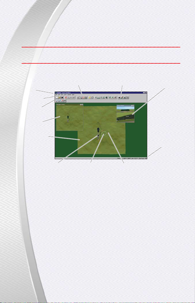
Menus
Edit Toolbar
Navigation
Toolbar
Navigation
Window
Work Window
Course Toolbar
Window Toolbar
Camera
A Selected Shape
Control Point
Camera Window
Status Bar
Page 10

✦ Depending on whether the shape is floating or has been
dropped, the contents of the right-click menus for that shape
vary. For more information, see Right-Click Menus on p. 93.
To see your course as it would appear in the game, activate and use the
Camera window. You can change the contents of the Camera window by
repositioning the camera, which is represented by a black camera icon in
the Work window.
➲ To move the camera, click and drag the icon in the Work window. The
contents of the Camera window are automatically updated.
➲ To rotate the camera, click and drag the black triangle that is part of the
camera icon. The contents of the Camera window are automatically
updated.
✦ Many shape manipulations can also be conducted through the Camera
window. For more information about the camera and the Camera window, see Camera Window on p. 20.
At the bottom of the application window is the status bar, which contains the location of the cursor and the point count of the underlying shape.
For more information, see Status Bar on p. 92.
Above the Work window, you can see the menu system and the toolbars
of the Course Architect.
✦ For more information about the contents of the menus, see Menus.
✦ For more information on the Edit, Course, Navigation and Window tool-
bars, see Toolbars on p. 89.
Through the menu system, you can access the Librarian, which lets you
place textures and objects in your project. For more information, see The
Librarian on p. 131.
✦ If you are having performance problems in the Course Architect, you can
toggle display of resource-intensive course elements through the Layers
tool. For more information, see Layers on p. 21.
99
99
Page 11

To get started:
✦ Prior to starting Course Architect, you should set your display to 1024 x
768 or higher in the Display control panel. For information on how to set
it, see the Windows® Help file.
1. Close all other applications, including the game.
✦ Before you begin designing a course, you should have an idea or plan
that you are trying to execute. To learn more about how to develop your
plan and other issues to consider before building your course, see Laying
Out a Course on p. 38.
2. Double-click the Course Architect icon. The program opens.
3. In the dialog box, click next to CREATE A NEW COURSE. Click BEGIN.
4. In the spaces provided, enter the name and description of your course.
➲ To define the entire workspace of your course, enter figures in the
length and height of the course. For the time being, accept the default
settings.
✦ Default measurements for length and height are in yards.
1 meter = 1.1 yards.
5. Make sure that the box next to Use New Course Wizard is checked.
.
NOTE:
NOTE:
The New Course Wizard is a very powerful tool for plac-
ing the holes and major land features of your course. This Quick
Start guide just touches on the basics of using it. For more information, see New Course Wizard on p. 25.
➲ To continue creating your course with the New Course Wizard, click NEXT.
6. Now, define the basic terrain of your course.
➲ To set the basic terrain of your course, check the box next to the appro-
priate location from the list on the left.
➲ To modify the degree of change in the terrain, use the slider bars on the
right.
✦ Change area indicates the amount of area in which the changes to ter-
rain are applied. A small change area combined with a severe change
makes for very up-and-down terrain.
✦ Severity indicates the amount of change in any given change area.
7. Click NEXT. Now, select the location of your course.
✦ The location that you select essentially defines the vegetation set used
when foresting areas in the New Course Wizard. Later, you can use vegetation from any of the installed course libraries.
8. Click NEXT. You can now place , water, forest areas and holes on the
map of your course. Holes can have pars of 3, 4 or 5.
111100
00
Page 12

➲ To save your work in the New Course Wizard, select SAVE
from the File menu.
NOTE:
NOTE:
It's highly recommended that you use the New
Course Wizard to place all of the holes of your course. Although
you can place holes in the Course Architect using the Hole
Definition tool, using the Wizard is much faster and easier. For
more information, see Hole Definition on p. 98.
➲ To place a hole, water or forest onto the course, click the appropriate tab
on the right side of the screen. Then, click and drag the appropriate icon
onto your course. The element is placed.
NOTE:
NOTE:
No hole or water shape placed in the New Course Wizard
can cross another one. A forest shape can overlap other shapes.
➲ To move the element to a different place, click and drag it. To rotate the
item, click and drag at one end of it.
➲ To place the element permanently on the course, click on it and then
click APPLY.
✦ Most dropped items can be picked up again and re-manipulated. After a
forest has been applied to plant trees, the trees cannot be picked up
again in the New Course Wizard.
Holes:
➲ To change the hole number for a selected hole, select a new number from
the Hole drop-down in the lower-right corner. Then, click APPLY.
NOTE:
NOTE:
Check the hole number to be sure that you are not
replacing an existing hole. The New Course Wizard overwrites the
existing one.
Water and Forests:
➲ To reshape a body of water or forest, click and drag one of the red con-
trol points in the shape to a new position.
➲ To place the water or forest permanently on the course, click APPLY.
9. When you have placed at least one hole on your course, click FINISH.
10.Your course is now created. You may begin using the other tools of the
Course Architect. For more information, see Tools on p. 72.
111111
11
Page 13

NOTE:
NOTE:
Save your course before you begin work. Select SAVE from
the File menu. In the dialog box, select a destination directory in which
to save your course. Enter a filename. Then, click SAVE.
✦ For detailed instructions on creating a hole, see Tutorial: Creating Hole 1
on p. 45.
OVERVIEW OF COURSE ARCHITECT™
OVERVIEW OF COURSE ARCHITECT™
The following sections survey the tools and features of the Course
Architect.
Each designer discovers his or her own strategy for designing in the
Course Architect. Because it is a flexible tool, you can develop the holes of
your course in an order that is most comfortable for you. However, it may
not be comfortable for your computer. The Course Architect application gen-
erates a high number of computations and can use large amounts of memory. When the application is performing a high number of computations,
your computer can slow down which, in turn, slows down your designing
process. Throughout this help guide, there are notations to inform you when
actions or features may slow down your computer. It is recommended that
you add these elements toward the end of the development.
A generalized strategy for designing a hole starts with a vision of what you
want to do. What is the basic shape and play for the hole? Does it start high
and end low? Is the green protected? Are there subtleties to each shot? How
challenging is the hole? Can aggressive golfers eagle the hole? How does the
hole fit into the overall design of the course? These questions affect the concept
for the hole and should be kept in mind during its design.
When you have a conceptual idea for the hole, you lay down the floorplan for the hole with the requisite land shapes (tee boxes and the greens)
and any other land shapes that you want to include (fairways, roughs, hazards, sand traps, et cetera). Then, in the Hole Definition tool, you unify the
placed elements as a single hole and lay down shot paths for the computer-controlled players to follow.
Most features of the hole are started in the Work window. This top-down
view of your course lets you lay the major elements, called shapes, and
apply textures to them to build course features such as fairways, greens,
bunkers, water, and tees. With the Measure tool, you can judge distances
between these areas to establish basic shots on the course. For example,
you can measure the distance between the tee and the first turn to calculate the club that is needed to reach it.
111122
22
Page 14
When you have laid one or more course shapes, you may
want to see how they appear in three dimensions. Represented
as a black icon in the Work window, the camera can be positioned to display contents of the course in three dimensions in the Camera
window. Changes made in the Work window are automatically updated to
the Camera window, provided that the camera is in position to view such
changes.
You can change the hole features in the Camera window, too. You can
select areas of the course and apply terrain changes to them—raise, lower,
flatten, smooth, and more. Changes in the Camera window are likely to ripple through the other hole features. Then, you return to the Work window
to tweak a few things. Then, you view the results again in the Camera window. This iterative process continues until you are satisfied with the results.
✦ When you want to test your work in the game, you can compile the
course to the game. For more information, see Compiling Your Course
on p. 147.
GOLF COURSE ELEMENTS
In a computer golf course, there are three basic components to design:
textures, terrain and objects. In the Course Architect, textures and terrain
are manipulated and placed with a tool called a shape.
A shape is a connected set of points that encompass a surface area on
the course. When a shape is created, it is floating on the course. While it
appears as a circular shape in the Work window, you can see that it is
indeed floating on the terrain of the course in the Camera window. While a
shape is floating, you can change the size, perimeter, and smoothness of
the shape through its control points. Control points are used to define the
perimeter of the shape. You can click and drag control points to change the
perimeter of the shape, and you can add, delete and rotate control points
to get the shape in perfect form.
111133
33
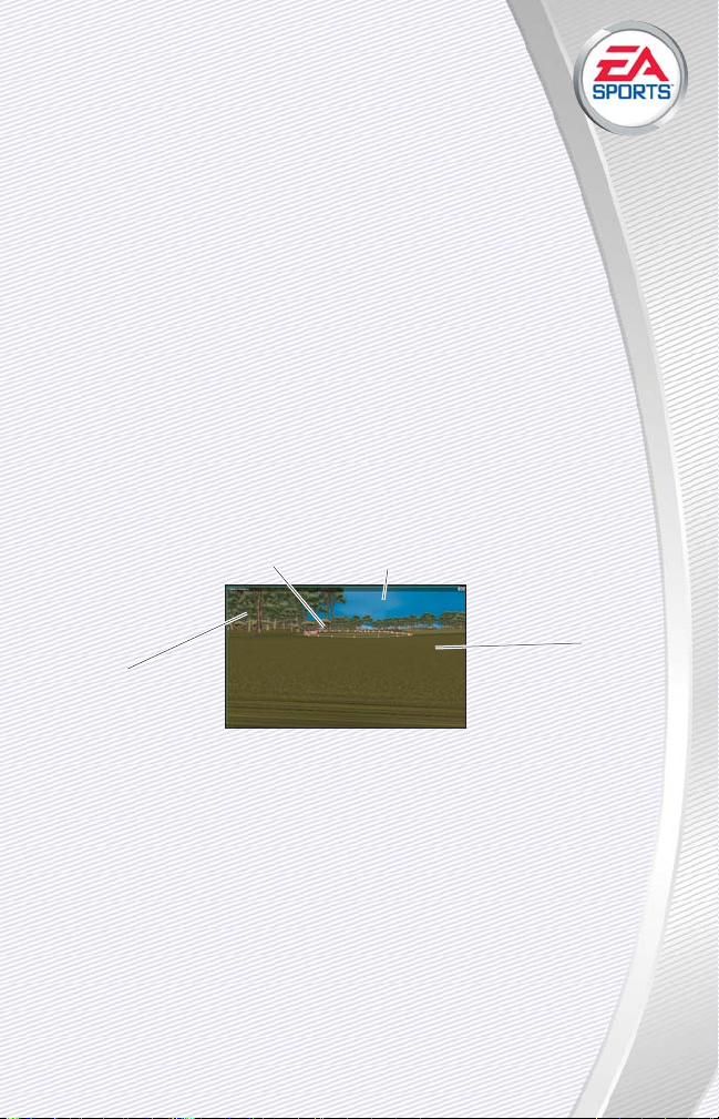
Panorama
Sky
Texture
Shape
Page 15

A floating shape must follow a set of rules:
✦ A shape cannot overlap any other shape, yet a shape can be completely
enclosed in another shape.
✦ The perimeter of a shape should not cross itself.
✦ For more information on shapes, see Shapes on p. 105.
You adjust the form of the shape to create features on your golf course
such as tee boxes, greens, fairways and bunkers. After you have defined
the perimeter of these features with the shape, you must apply a texture to
them. In general 3D graphic tools, a texture is a graphic image that is
applied to the exterior of a 3D mesh. In the Course Architect, you apply
specialized textures to shapes to assign a playing surface to it. When you
choose a texture to display on your shape, you are selecting by extension a
set of play characteristics. For example, when you apply a sand texture to a
shape, you produce a sand bunker. In the game, when a golfer hits a ball
into the sand, the specialized texture informs the game to play a soft sound
and to proceed with the code that calculates the roll and the lie of the ball
based on the trajectory of the shot.
✦ You can identify one or more sections of the course as a hazard area.
When a ball lands in a hazard area, the hazard rules of golf apply. For
more information, see Create Hazard Area on p. 74.
After the texture has been applied to the shape, to make the textured
shape a permanent part of the course, you must drop the shape. The shape
now becomes a terrain object, which is a series of interconnected breakline
points in the terrain.
You use shapes to manipulate the underlying terrain, too. Terrain refers to
the shape of the land. Terrain greatly influences the play characteristics and
appearance of a hole. Is the land raised or lowered? Are there depressions
and hillocks on the hole? Does the land have features that are consistent
throughout the entire course? In a regular golf course, terrain decisions are a
major component of the development effort and are expensive to undo.
In a computer course, creating terrain features is a matter of pointing
and clicking. The terrain of a computer course is described by a mesh of
touching triangles, called faces. These triangles are sized and placed together to describe a 3-dimensional grid, called the mesh. You push and pull a
seamless mesh that, in total, describes the outer shell of a 3D shape. When
you manipulate a 3D shape, the computer changes the shape of the mesh
111144
44
Page 16

to seal it. Think of a wire mesh. You can change the shape of
the mesh, and the loops adjust their size to accommodate.
To manipulate the terrain, you can 1) lift the shape used to
define the course feature above or 2) create another shape and use it as a
frame to make changes to the terrain underneath it. Through the first
method, you can define areas of the course that have a single shape with a
single texture on them. For example, you can create an elevated tee box by
changing the perimeter of a shape, applying a texture, dropping the shape
and then lifting it to use to elevate the terrain. Through the second method,
you can create terrain features that cross over multiple course features. For
example, you can create a bunker that is part of a slope below the green.
Terrain manipulations can be applied over multiple dropped shapes.
✦ Shapes are the fundamental tool for designing your courses and should
be well-understood by every designer. For more information, see
Shapes on p. 105.
On top of the terrain, you place objects and structures. Objects like trees
and rocks can be added to give authentic flavor and interesting variation to
your golf course. Additionally, you can add structures such as houses, shacks
and clubhouses to make it feel like a real golf course. These 3D objects have
the appearance and play characteristics of their real-world counterparts.
✦ For more information on objects and structures, see Objects on p. 130.
In summary, the following steps loosely describe the order of development for defining and shaping an area of your course:
1. Create a shape. Move its control points to reshape it.
2. Apply a texture. Drop it into the terrain.
3. Use the same shape or create a new one. Move its control points to
reshape it.
4. Use the Course tools to change the underlying terrain.
5. Add objects and textures to the area.
Applied many times across your project, this iterative process produces
the terrain and course features of your ideal course. Then, you can add the
touches described in the following section.
111155
55
Page 17
ADDITIONAL COURSE ELEMENTS
HOLES
A full golf course is composed of eighteen holes. In Course Architect, the
hole is the basic unit of development; to build a course, you build eighteen
separate holes.
SKIES AND PANORAMAS
Other features that can be included are panoramas and skies. Panoramas
give the appearance of the horizon in photographic detail, and you can select
which panorama you want to appear along the perimeter of your course. The
skies fill in behind the panorama, and you can view your course under various sky conditions through the Sky Picker tool. The panoramas and skies of
the Course Architect have been designed to seamlessly blend together.
✦ For more information on the Sky Picker tool, see Sky Picker Tool on p. 84.
SHADOWS
Tiger Woods PGA TOUR 2003 automatically computes the sun's shadows
over objects like trees, rocks, and other terrain features. In the game, users
can choose to display these lighting effects. When your course is compiled
to the game, players can toggle display of shadows, as shadows can be
very demanding of system resources. Water reflections are also selectable
for display in the game only.
DESKTOP ELEMENTS
111166
66
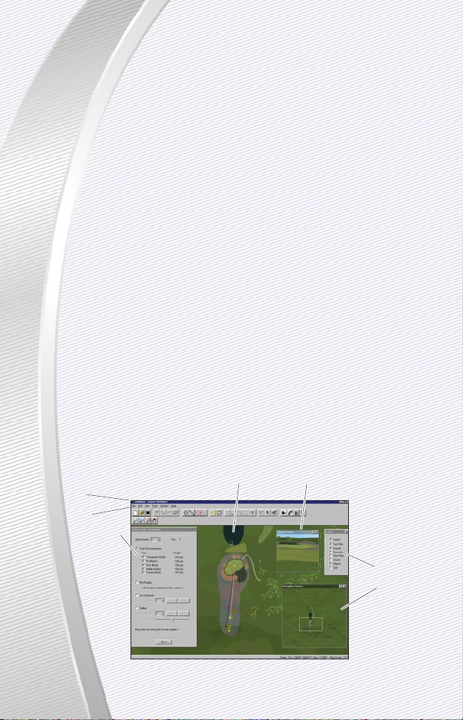
Menus
Toolbars
Hole Definition
Tool
Layers Tool
Navigation
Window
Camera Camera Window
Page 18

Click on any of the following links to learn more about a type
of element found on the desktop of the Course Architect. You
can browse the information here to get a better understanding
of the structure of the tool. Or you can use it as a reference.
✦ Prior to starting the Course Architect, you should set your display to
1024 x 768 or higher in the Display control panel. For information on
how to set it, see your Windows Help file.
✦ Work window - Tools and functions of the main application window.
✦ Camera window - Tools and functions of the Camera window, which
displays the course from a 3D camera’s point of view.
✦ Camera - Placement and settings for the camera icon, which deter-
mines the contents of the Camera window.
✦ Navigation window - Tools and functions to display different areas of
your project in the Work window.
✦ Hole Definition tool – Define gameplay elements of a hole on the
course.
✦ Menus - All menu items and functions, sorted by menu.
✦ Right-Click Menus - Descriptions of the right-click menus that appear
based on what has been selected in the Work window.
✦ Toolbars - Descriptions and contents of each of the five toolbars.
QUITTING THE PROGRAM
➲ To safely exit the program, select EXIT from the File menu.
✦ If prompted, save your work , or unsaved changes will be lost.
WORK WINDOW
The Work window gives you the best perspective on the course. From
this top-down view, you can see the shapes and objects that populate the
area of the course beneath. Most course creation and editing work is done
in the Work window, including object positioning, shape selection and elevation changes.
When a project is opened in the Course Architect, the Work window is
visible at all times. Its contents can be changed with the Navigation tools in
the toolbar, and those contents can be zoomed in or out.
✦ The Work window can float inside the Course Architect application win-
dow or can be maximized to fill the window.
111177
77
Page 19

In the Work window, you can place the camera. The camera looks out on
the course and projects what it sees in the 3-dimensional view in the
Camera window.
✦ At the bottom of the Work window is the status bar, which contains
important positional information about the cursor. For more information,
see Status Bar on p. 92.
CONTENTS OF THE WORK WINDOW
The Work window lets you change its contents to display the entire map
of the course or a part of a land shape that is no more than a few inches
across. With the Zoom tools in the Navigation bar, you can change the focus
of the Work window's camera.
➲ To zoom in and out on your hole, click the Zoom tool. To zoom in, left-
click. To zoom out, right-click. You can zoom in and out multiple times.
➲ To scroll the Work window, use the Arrow keys. Or, click the Grab tool.
Click and drag the hand icon over an area in the Work window on which
you want to view. The Work window is updated to focus on this selected
area.
➲ To return the view for the Work window to its default height and focus,
click the Cancel Zoom button.
➲ To zoom in on a specific area of the Work window, click the Zoom Select
tool. Click and drag a rectangle around the area in the Work window on
which you want to zoom. The entire contents of the rectangle are then
displayed in the Work window.
111188
88
Selected Shape
Camera Aiming
Triangle
Camera
Zoom
Zoom select
Grab
Cancel zoom
Other Floating
Shape
Hazard Area
Page 20

➲ To resize the Work window, click and drag from the lower-
right corner of it.
✦ You cannot resize the Work window if it is maximized. To
make the Work window float in the Course Architect application, select
FLOAT from the Work sub-menu of the Window menu.
➲ To focus the camera on a shape, select the shape in the Work window.
Then, select AUTO FOCUS CAMERA from the View menu. The camera
now focuses on your selection.
➲ To center the camera in the Work window, select CENTER CAMERA from
the View menu or press
v+ C
.
➲ To edit the fundamental properties of the current hole or to define a set
of unrelated shapes as a hole, select HOLE DEFINITION TOOL from the
Tools menu. For more information, see Hole Definition on p. 98.
SHAPES IN THE WORK WINDOW
➲ To create shapes in the Work window, select CREATE LAND SHAPE from
the Tools menu. Click a location in the Work window. Then, click to
define the control points of your shape. Right-click to finish the shape.
For more information, see Shapes on p. 105.
➲ To define the type of texture in your shape, click the shape and then
right-click in it. Select PROPERTIES. Select the texture type from the
drop-down list and click OK. The texture becomes visible when you drop
the shape. For more information, see Textures on p. 107.
GRID SIZE
You can layer a grid of dots on top of the Work window. For placing and
aligning objects and shapes, it is a useful feature.
➲ To toggle display of the grid, press
G
.
➲ To change the size of the grid, select GRID SETTINGS… from the Tools
menu or press
q+ G
. For more information, see Grid Settings on p.
86.
111199
99
Page 21
NAVIGATION WINDOW
Unlike tools that require courses to be developed hole by hole, the
Course Architect lets you move around your entire course to focus on various pieces of it as needed. The primary tool for navigating your course is
the Navigation window. The Navigation window lets you change the contents of the Work window so that you can work on different parts of the
course, as you see fit.
➲ To toggle display of the Navigation window, select NAVIGATION from
the Window menu.
➲ To change the contents of the Work window, zoom in and reposition the
focusing rectangle in the Navigation window. The Work window is automatically updated.
NOTE:
NOTE:
Displaying the Navigation window can impact perform-
ance. To increase performance in the Course Architect, deselect
display of the Navigation window in the Window menu.
CAMERA WINDOW
When developing 3D art on a computer, you are confronted with an irresolvable fact: you cannot display three-dimensional objects on a 2D screen
without some form of interpretation. In the Course Architect, this interpretation is the Camera window.
➲ To toggle display of the Camera window, select CAMERA from the
Window menu.
222200
00
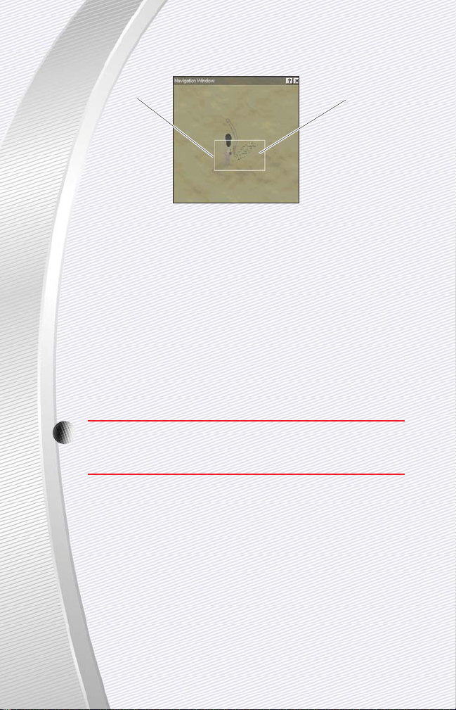
Focusing Rectangle
Contents of the
Work Window
Page 22

The Camera window displays what is viewed from the camera that is
placed in the Work window. The Camera window is your eye on the course.
If you were playing the course as a golfer in the game, you may see the
course as it is displayed in the Camera window.
✦ You can select and manipulate shapes in the Camera window as you do
in the Work window.
➲ To resize the Camera window, click and drag any side or corner.
The Camera window is a powerful tool that gives you infinite perspectives on the course through repositioning the camera. For more information,
see The Camera on p. 22.
TERRAIN
The Camera window is the best place to fine-tune your terrain features. While
you can start large-scale terrain features such as hills and ridges in the Work
window, you can give them subtlety and definition in the Camera window.
The multiple terrain selection tools allow you to highlight terrain pieces of
any size and shape. With the terrain tools, you raise, lower, tilt, flatten,
smooth, and add noise to them. For more information, see Terrain on p. 120.
LAYERS
The Layers tool allows you to select and deselect course elements to display in the Work window. Depending on the capabilities of your computer
and the size and contents of the Camera window, you may notice an
impact on the performance of the Course Architect. In such cases, it may be
a good idea to deselect the display of some course elements, so that you
can concentrate on the work that needs to be done, and the computer can
concentrate on updating the screen with your changes.
➲ To open the Layers tool, select LAYERS from the Tools menu. In the
Layers tool, toggle display of layers that you do not need to see currently. Close the pop-up window. The Work window is updated.
222211
11
Panorama
Texture
Shape control points
Selected shape and
underlying terrain
Page 23
PICKING SKY AND PANORAMA FROM THE CAMERA WINDOW
To get the right look for the sky and the panorama of your course, you
can define these elements from inside the Camera window.
➲ To choose a different sky, right-click on the sky in the Camera window.
Select CHOOSE SKY DOME. The Sky Picker Tool opens. For more information, see Sky Picker Tool on p. 84.
➲ To choose a different panorama, right-click on the sky in the Camera
window. Select CHOOSE PANORAMA. The Choose Panorama window
opens. For more information, see Panorama Properties on p. 85.
THE CAMERA
When the Work window is active, you can move the camera and update
the Camera window. In the Work window, the camera is represented by a
black square with a triangle attached to one end of it. The open side of the
triangle indicates the direction in which the camera is pointed.
➲ To toggle display of the Camera window, select CAMERA from the
Window menu.
➲ To focus the camera on a different area of the course, click and drag the
camera icon to a new location in the Work window. The Camera window
is automatically updated.
➲ To move the camera without redisplaying the Camera window, hold
v
down while you click and drag. Make your position changes.
Then, release
v
to update the Camera window.
TIP:
TIP:
If you are experiencing slow times in refreshing the camera,
you may want to use the above method for moving the camera. It
is also useful for making very fine movements of the camera.
NOTE:
NOTE:
If you mistakenly drag the camera out of the Work win-
dow and into the Camera window, press
v+ C
to center
the camera back in the Work window.
➲ To rotate the camera, click and drag the triangle on the camera icon to a
new position. The Camera window is automatically updated.
222222
22
Aiming triangle
Page 24

✦ You can also change the height and angle of the camera. For
more information, see Camera Properties below.
➲ To center the camera in the Work window, select CENTER
CAMERA from the View menu.
➲ To focus the camera on what is currently selected in the Work window,
select AUTO FOCUS CAMERA from the View menu.
A NOTE ABOUT 3D DIRECTIONS
Movements in three-dimensional space can be described in three directions. Stand up from your computer. Let's call the position where you are
located, "Point A."
The X-direction refers to steps to the left or right of Point A.
The Y-direction refers to changes in elevation from Point A. From where
you're standing, movements in the Y-direction require you to jump into the air or
dig into the ground. Before you get a shovel, let's get back to the computer.
The Z-direction refers to steps to forward or backward of Point A.
Often, movements can be described in planes. A plane is a perfectly flat
surface that extends to infinity. Imagine an infinitely floor—a plane. In 3D
space, the X-Y plane refers to all of the positions that can be described as
movements in the X-direction or the Y-direction—not the Z-direction. While
you can describe movements in the other two planes (X-Z plane and Y-Z
plane), most planar movements in the Course Architect are described in the
X-Z plane and the Y-direction.
CAMERA PROPERTIES
The Camera in the Course Architect can be positioned at any angle to
display the viewed terrain in the Camera window. Through the Camera
Properties dialog, you can position the Camera's elevation, pitch and direction as needed.
✦ Elevation indicates the height at which to place the camera above the
terrain.
NOTE:
NOTE:
When the camera is placed high above the terrain, small
changes in elevation are difficult to see in the Camera window. To
see small changes in elevation, position the camera close to the
ground. Position the camera about nine feet off the ground to
view the course as you would see it when the course is played in
the game.
222233
33
Page 25

✦ Pitch points the lens of the camera at an angle relative to the horizon.
For example, a pitch of –10 degrees aims the camera at a slightly downward angle.
✦ Direction measures that angle at which the camera is pointed. An
angle of 0 degrees points the camera at the top of the screen.
➲ To open the Camera Properties, right-click on the camera icon in the
Work window. Then, select PROPERTIES. Make changes as needed. To
accept the changes, click OK. To close the Camera Properties dialog box
without making changes, click CANCEL.
NOTE:
NOTE:
Rendering the view of the camera can take time if you
have a lower-end machine. If you are experiencing an impact on
the Camera window’s update speed, you might consider opening
the Camera window only when you need to proof your work. Or,
you can deselect the display of some layers in the Work window.
For more information, see Layers on p. 21.
HOLE DEFINITION TOOL
You can define a set of shapes in the Course Architect as a course hole
through the Hole Definition tool. By identifying the tees, greens and shot
paths of a hole in the Hole Definition tool, the hole is defined.
➲ To open the Hole Definition tool, select HOLE DEFINITION TOOL from the
Tools menu, or you can click the Define Holes button on the Course toolbar. For more information about defining holes inside the Course
Architect, see Hole Definition on p. 98.
✦ You can also define holes through the New Course Wizard. For more
information on the New Course Wizard, see New Course Wizard on p. 25.
GETTING ST
GETTING ST
ARTED
ARTED
Getting started in the Course Architect is easy. Finishing a course takes
some work, but the tools of the Course Architect hopefully make that work
fun to complete. This chapter discusses how you can begin to develop
entire golf courses in the Course Architect. At the conclusion of this chapter,
you should have enough information to begin development of your own
project and references to other parts of the documentation to explore topics
in depth.
222244
44
Page 26

✦ Prior to starting Course Architect, you should set your display
to 1024 x 768 or higher in the Display control panel. For
information on how to set it, see your Windows Help file.
➲ To start Course Architect, double-click the Course Architect icon or use
the Windows Start menu. The program opens. To begin creating a new
course with the New Course Wizard, check the box next to Create a
New Course. Then click BEGIN. For more information on creating new
courses, see New Course Wizard below.
NOTE:
NOTE:
When you are using Course Architect, it is highly recom-
mended that you close all other programs. The tool needs as
much RAM as your system can maximally provide.
NEW COURSE WIZARD (NCW)
When you begin to build a new course, you have two choices for your
approach. You can build the course from scratch, or you can use the New
Course Wizard to set the basic course parameters, terrain characteristics and
location. The New Course Wizard gives you a good start towards building an
entire course and is recommended for beginning and expert designers.
You can use the New Course Wizard to lay out some basic terrain elements, water, forests and one or more of your holes. The layout tools are a
sub-set of the entire set of Course Architect tools and are primarily intend-
ed to get the basic shape and position of course elements. However, if you
do know exactly what you want, with each hole positioned in a precise
location, the New Course Wizard lets you complete your layout to that level
of detail.
NOTE:
NOTE:
To start a new project, you should check first to see that
you have enough space. To start, you should have at least 200MB
of free hard drive space—as much as possible, really.
Course Architect from EA SPORTS lets you build the golf course of your
dreams. Or you can recreate any of the twenty-seven courses on the PGA
TOUR. A specialized suite of graphical tools puts the bulldozers, landmovers,
and lawn mowers at your fingertips.
222255
55
Page 27

ADVANTAGES OF THE NEW COURSE WIZARD:
When you use the New Course Wizard, you can accomplish quite a bit
with a minimum of effort. In the Course Architect, the following features
are available only through the New Course Wizard:
✦ Randomize terrain. After you enter a few parameters, the New Course
Wizard can create realistic terrain that blends together yet retains a
sense of randomness. You can create overall effects from flat swampland to rugged mountains.
✦ Place entire holes. In the New Course Wizard, you can place the basic
elements for entire holes. You do not have to place the fairways, tees,
greens and shot paths individually.
✦ Apply entire foresting libraries. The New Course Wizard lets you pop-
ulate entire forested areas with a selection of trees from the library of
your choice. It's a quick way to create natural populations of flora.
✦ Speed and ease of laying out all 18 holes. In a very short period of
time, you can lay out all of the major features of your course, including
all water areas, forests and all 18 holes. It’s a great way to start.
BEFORE USING THE NEW COURSE WIZARD
If you are ready to begin development of a course, you may want to do
some pre-production work prior to beginning the New Course Wizard.
NOTE:
NOTE:
When you develop a course, you can use the New Course
Wizard one and only one time. Therefore, it's wise to know
what you're trying to accomplish with the tools in the New Course
Wizard prior to using them.
The following elements should be considered prior to beginning development with the New Course Wizard:
✦ Size. What are the length and the width of the golf course? What is the
total area that you are going to design? Keep in mind that you should
have at least 10% extra area on the sides of your course for appearance
and design reasons. At a later time, you can trim off this fat as needed.
✦ Terrain features. What are the major terrain features of your course? A
giant mountain on one side? A lake around which the course is created?
Do sections of forested area dapple your course? You can build rough-cut
versions of these features inside the New Course Wizard.
222266
66
Page 28

✦ Location. Where is your course located? If you know the
geographic location of your course prior to using the New
Course Wizard, you can place textures and some objects.
✦ Hole placement. How much do you know about the placement of the
holes on your course? Do you know the angular orientation of each
hole? Do you know the distances between each hole? If possible,
acquire or draw a map of the basic hole locations and relationships
before beginning.
✦ Hole par. What is the par for each hole? Based upon the par for a hole,
you can select from one of several basic shapes. Standard total par for
an 18-hole course is 72.
1. COURSE NAME & SIZE
1. To begin creating your new course, select NEW from the File menu. The
New Course window opens.
2. In the spaces provided, enter the name and the Course description infor-
mation.
✦ The Course Name appears in Tiger Woods PGA TOUR 2003 in the Select
Course screen. It is not a filename.
3. In the Height and Width boxes, enter the total dimensions for the land
plot that you want to use for creating your course.
NOTE:
NOTE:
Be sure to give yourself at least a 10% cushion on each
dimension. You may need the extra room. Also, the blending of
the terrain with panoramas and skies works better if you give
yourself a bit of room to create the appropriate perspective.
✦ If you know the course dimensions in meters but the display is in yards, quit
the New Course Wizard. Then, select USE METRIC under the View menu.
Select NEW from the File menu to begin again the New Course Wizard.
222277
77
Page 29

4. To use the New Course Wizard, you must check the box next to Use
New Course Wizard.
5. Click NEXT. The New Course Wizard begins.
2. BASIC COURSE TERRAIN
After defining the name, description and size of your course, you must
configure the basic terrain for it.
1. On the left-hand side of the Randomize Terrain, you select the basic
topography of the terrain. Click the button next to the general type of
terrain to use. When you make a selection, the slider bars on the right
side of the screen change automatically.
2. After you select the basic terrain type, you can make adjustments to the
terrain with the slider bars on the right side of the dialog box.
✦ Change area indicates the amount of area in which the changes to ter-
rain are applied. A small change area combined with a severe change
makes for very up-and-down terrain.
✦ Severity indicates the amount of change in any given change area.
3. When you have finished making your adjustments to the basic terrain,
click NEXT. The Course Location window opens.
3. COURSE LOCATION
222288
88
Basic terrain type Area of changes
Severity of changes
within that area
Page 30

NOTE:
NOTE:
If you do not see a dialog box at this juncture,
then you did not choose to use the New Course Wizard.
You can either begin using the Course Architect to build
your course from scratch or start again with the New Course
Wizard. To begin creating your course again, select NEW from the
File menu. Make sure the box next to Use New Course Wizard is
checked.
1. In the Course Location window, you are essentially selecting the default
library to add to your course. Here are brief descriptions of the available
libraries:
✦ Northern California Coast: Library from Pebble Beach, Poppy Hills, and
Spyglass courses.
✦ Southeastern US: Library from TPC at Sawgrass course.
✦ UK Coast: Library from Royal Birkdale course.
✦ Tropical: Library from Princeville course.
✦ Rocky Mountains: Combo library of large pines and deciduous trees
from TPC at Sawgrass and Pebble Beach.
✦ Palm Springs: Combo library of palms from TPC at Sawgrass and
Princeville and desert-looking vegetation from other libraries.
Later, from inside the Course Architect, you can access libraries that con-
tain objects and textures from other environments. For more information,
see The Librarian on p. 131.
2. When you have selected your location, click NEXT.
222299
99
Page 31

4. NEW COURSE WIZARD
You are now placed in the New Course Wizard, where you can use
placement tools to create, position and drop entire holes, water and forests
into your course.
NOTE:
NOTE:
You can save your work in the New Course Wizard. Select
SAVE from the File menu.
These tools allow you to do the first pass at designing your course. You
can position and shape the large-scale features, but the New Course Wizard
is probably not the right method for fine-tuning your course.
TIP:
TIP:
For some of our in-house designers, the best way to use
the New Course Wizard is to create a large-scale terrain feature,
such as a lake or a major forested area. Using the feature as a
point of reference, you can then position the holes that abut the
feature. After that, your development efforts are probably best
realized with the tools on the Course Architect desktop.
On the left side of the screen, you can see the course as it has been
designed using the terrain and location selection tools. Areas of lighter color
indicate higher elevations, with darker colors representing lower elevations.
333300
00
Zoom
Zoom select
Cancel
Page 32

➲ To zoom in on a particular area, click the Zoom button and
then click on the location where you want to zoom.
➲ To select an area to fill the display of the NCW Work window,
click the Zoom Select button. Click and drag a rectangle around the area
that you want to display in the NCW Work window.
➲ To return the NCW Work window to its starting position, click the Cancel
Zoom tool.
NOTE:
NOTE:
In the New Course Wizard, you cannot tweak the terrain
beneath the elements that you place. Don't worry about the
details for now; the Course Architect has plenty of tools to get the
right effect.
On the right side of the screen, you can see the tabs and tools to select
and place elements on the course.
➲ To place an element, click on the proper tab. A list of icons is displayed.
When you decide the basic shape that you want to use, click and drag
the icon onto the NCW Work window. The shape appears in the window
as a floating shape and can now be repositioned. Water and forest
elements can be reshaped, too.
➲ To drop the shape into the terrain, click APPLY. The element is now part
of the terrain.
➲ To undo your most recent action, press
v+ Z
.
➲ To delete the selected shape, press
m
.
➲ To finish using the New Course Wizard, click FINISH.
Rules for placing elements:
When you place elements in the New Course Wizard or with the Course
Architect tools, the following rules apply:
✦ Shape lines should not cross over themselves.
✦ Shape lines cannot cross over other water or holes.
Notes on the particulars of placing each type of object are listed in the
following sections.
333311
11
Page 33

A. WATER AND FORESTS
When you place a body of water or forest on the course, it appears as a
floating shape. You can reposition and reshape this figure to get it to fit
appropriately on the course.
NOTE:
NOTE:
When you create a water shape in the New Course
Wizard, the underlying terrain still retains the generated elevations and depressions. Unless you are creating a moving stream,
you may want to reshape and then flatten the terrain beneath the
water in the Course Architect with the Smooth tool. These tools
are available after you finish the New Course Wizard. For more
information, see Smooth an Area on p. 80.
TIP:
TIP:
To create an island in the middle of water, create the water
shape in the New Course Wizard (or later in the Course Architect)
and then later create a shape inside of the water shape. Use the
Make a Hill tool to lift the shape out of the water. Then, apply a
land-type texture to it, and you've got an island.
➲ To reposition the shape, click and drag it to a new location.
➲ To change the shape, click and drag one of the control points to a new
position.
NOTE:
NOTE:
You cannot add or remove control points in the New
Course Wizard. However, you can place the shape in the Wizard
and then lift and reshape it later inside the Course Architect.
➲ To place the shape into the terrain, select the shape. Then, click APPLY.
The shape is placed into the terrain.
➲ To delete the shape, select the shape. Then, press
m
. The shape is
removed.
Notes on placing forests:
Placing forests is very similar to placing water. The location that you
chose determines the type of vegetation that you can use.
NOTE:
NOTE:
In the Course Architect, you can configure the height, variation of height and density of your forested areas. These options
are not available in the New Course Wizard. For more information,
see Foresting Tool on p. 81.
333322
22
Page 34

B. CREATING HOLES
In the New Course Wizard, you can place and rotate entire
holes whether they are par3, par4 or par5.
Rules for creating and placing holes:
✦ Holes cannot cross over themselves.
✦ Holes cannot cross over water or other holes.
✦ Holes cannot encompass water or other holes.
To place a hole:
1. To place a hole in the New Course Wizard, you first select the number of
the hole that you are about to create.
✦ It's not necessary to create all eighteen holes or to create them in
numerical order.
➲ To select a hole to place, use the up and down arrows on the Hole
Indicator in the lower-right corner of the screen.
NOTE:
NOTE:
In the Course Architect, you can place the Driving Range,
Chipping Area and Putting Green for your course. However, you
must do so from within the Hole Definition tool, which is not part
of the New Course Wizard. For more information, see Hole
Definition on p. 98.
2. Now, select a hole template based on the par for the hole. Click the tab that
indicates the par from the hole. From the list of basic shapes, choose one
that you want to use. Click and drag it into the NCW Work window.
NOTE:
NOTE:
A standard course has a total par of 72, which averages
to a par of 4 on each hole. Therefore, to make a standard course,
you should have an equal number of par 3's and par 5's; many
courses have four par 3's and four par 5's.
✦ After you add the hole to the project, you can rotate it so that it match-
es the orientation that you need.
3. When the hole is placed, you can reposition it as needed.
NOTE:
NOTE:
Because of the scale of the New Course Wizard, it can be
difficult to see if one shape is crossing over another shape. So, it's
recommended that you avoid getting too fine in your placement
and rotations. You can make subtle adjustments using the Course
tools in the Tools menu of the Course Architect.
333333
33
Page 35

➲ To reposition a hole, click and drag it to a new location.
➲ To rotate a hole, click and drag at one end of the hole until the hole is
oriented in the correct direction.
4. When you are satisfied with the placement of the hole, you must drop it
into the course.
➲ To drop the hole into the course, select the hole in the NCW Work win-
dow. Then, click APPLY.
NOTE:
NOTE:
When the Course Architect attempts to drop a hole into
your project, it performs a number of checks to ensure the consistency and viability of your project. If an error is reported, it must
be corrected before the hole can be placed in the project.
➲ To delete the hole and start over, press
m
.
✦ After you finish up with the New Course Wizard, you can create holes
through the Hole Definition Tool. For more information, see Hole
Definition on p. 98.
5. FINISH
When you press FINISH, the New Course Wizard completes the final
actions to embed the water, forest and holes that you placed into the terrain. These objects are now part of your project.
You are now in the Course Architect, with the beginnings of your course
displayed. Your first task is to save your course.
➲ To save your course, select SAVE from the File menu. Navigate your
local hard drive to find a location for your project.
✦ It's recommended that you create a new folder and label it with the
name of your course. Save your project inside this folder.
NOTE:
NOTE:
After you have started your project, it's okay to move your
.TCA files. However, to move .TCL (library) or .CRS (course) files,
use the Course Utilities. For more information, see Course Utilities
in your game documentation.
➲ To see your project in a 3D perspective, select CAMERA from the
Windows menu. Then, select CENTER CAMERA from the View menu to
place the 3D camera in the center of the Work window.
333344
44
Page 36

Your project is saved in one file with the extension .TCA. In
addition to the .TCA file, your course may use one or more
course libraries (.TCL). It's likely that these files are not stored in
the same directory, but the Course Architect knows where to find them.
WHEN USING COURSE ARCHITECT
WHEN USING COURSE ARCHITECT
,
,
save your work on a regular
basis. Your project may take more than one day to complete. It’s a good idea
to back up your work on a regular basis..
You can now begin to design in earnest. For more detailed information,
see the following topics in this documentation:
✦ Overview of Course Architect (p. 12). An overview of the Course
Architect desktop.
✦ Tutorial: How to Create Hole 1 (p. 45). A step-by-step tutorial for how
to create a hole from scratch outside of the New Course Wizard. Also,
tutorial covers how to create key course elements such as cart paths
and sand traps.
✦ Command Reference (p. 52). An explanation of all of the menu and
toolbar commands.
SAVING YOUR WORK
When you are loading and saving projects, keep the data on a local
drive. Do not load your projects from external media or from a connected
network. Performance can be significantly impacted.
➲ To save your project, select SAVE from the File menu.
✦ The default directory for saved projects is C:\My Documents. You can
choose to save in any directory.
➲ To save a version under a different name, select SAVE AS… from the
File menu.
✦ The Save As feature is useful if you are engaged in major changes to
your course or if you want to experiment without committing to the
change.
➲ To open a different project, select OPEN from the Project menu. If
prompted, you can choose to save your current project.
333355
55
Page 37

LOADING A COURSE
To load your project, you load the Course Architect file. These files end
with the .TCA extension.
✦ To load a project, select OPEN from the File menu. Navigate to the fold-
er where you initially saved your project. Select the .TCA file and press
OPEN. Your project opens.
✦ If you cannot see your project file, make sure the Files of Type box
reads, "Course Architect File".
The Course Architect file contains all of the data necessary to describe
the contents of your course. It does not contain the object and texture
libraries that contain those elements; in the Course Architect file, objects
and textures are stored as references to the libraries that are automatically
loaded when you load the Course Architect file.
When you are loading and saving projects, keep the data on a local
drive. Do not store your projects on external media or on a connected network. Performance can be significantly impacted.
333366
66
Page 38

ERASING YOUR WORK
In Course Architect, mistakes aren’t as costly as on a real golf
course. Instead of rehiring the landmovers, contractors, and labor to
correct mistakes, a few mouse clicks can undo or erase your worst blunders.
UNDO
If you make a simple mistake, undo it.
➲ To undo the last action, select UNDO from the Edit menu, or press
v+ Z
.
DELETING SHAPES
You can remove shapes and points of shapes very easily in Course
Architect.
➲ To remove a floating shape, a dropped shape or a control point, right-
click on the item in the Work window. Select DELETE. The item is deleted.
✦ If the dropped shape has shapes enclosed by it, select DELETE WITH
CHILDREN to delete all of the shapes.
DELETING HOLES
✦ For more information on deleting holes, see Deleting a Hole on p. 104.
DELETING COURSES
➲ To delete a course, exit Course Architect. Open the Course Utilities. For
more information, see Course Utilities in your game documentation.
COMPILING COURSES
Even if your course is not completed, you can compile your course to the
game to test it. When you compile a course, the tool saves the output files
in the proper directory for use in the game. Use this feature to test your
partially completed courses or to compile finished courses for your system
or to share with friends.
When you are ready to compile your course, you can do so quickly
through the Course Architect.
NOTE:
NOTE:
You can compile courses to Tiger Woods PGA TOUR 2003
only.
333377
77
Page 39

➲ To compile your course for use in the game, select COMPILE COURSE…
from the File menu.
➲ To make the course immediately available to the game, check the box
next to Register Course.
✦ For more information on the specifics of compiling a course, see
Compiling Your Course on p. 147.
LALAYING OUT A COURSE
YING OUT A COURSE
On a computer golf course, you don’t have to walk from hole to hole.
When you complete a hole, the computer simply places you at the tee for
the next hole. Consequently, you never see the course on a scale larger
than the individual hole.
However, the best courses in the world have a consistency from hole to
hole. On each hole, you can see familiar terrain shapes that are integrated
into the topography of the course location. When done right, this consistency has a harmonious effect on the golfing experience. You feel like you’re in
a peaceful and carefully considered environment.
The fundamental element of a golf course is the individual hole, and the
tools of the Course Architect emphasize this orientation. So, to account for features and issues on a scale larger than the individual hole, you need to plan
ahead. This chapter provides some design points before you start digging.
BASIC DESIGN DECISIONS
DRAMA VS. REALISM
Before you begin to work on your course, you should make some essential
decisions. Are you making a realistic course or a fantasy course? Or are you
making something in between? Your decision can influence how you complete your course. A realistic course requires more patience and adherence to
pre-defined course features, including accurate terrain creation, hole positioning and orientation and attention to the details of the course. After all, you
don't want to make mistakes in Amen Corner, as a golfer or as a designer.
COURSE LOCATION AND DEGREE OF DIFFICULTY
Secondly, you need to place your course in a particular climate and geological environment. Is it a coastal course or an alpine course? How much
does the natural surrounding terrain impact the course? These decisions
affect which elements such as objects, textures, panoramas, and terrain
shapes are used on the course.
333388
88
Page 40

You should also consider how difficult you want the course to
be. Is it a championship-level course? How long is the course?
What is the par?
✦ A typical format for a course might be four par 3’s, four par 5’s, and the
rest as par 4’s. Such an organization produces a par 72 course.
You should consider how you want to distribute the holes on your
course. A par 3 hole doesn’t necessarily imply an easy hole; your tee shot
could be very challenging. Does your course get easier or harder as the
holes progress? How do you want the course to finish? Does it end on a par
5, so that a second-place golfer can make up a stroke or two?
And finally, what elements of your course are going to stand out as
unique? What are its risks? What are its rewards? Do you have signature
holes? Unusual terrain? Or is it just a great round of golf?
While you may not have answers to all of the above questions, it's important that you know what you don't know. It's reasonable to postpone resolution until you're actually shaping the course with the Course Architect tools.
However, you should be aware that making large-scale changes can be very
expensive in terms of time when you are far along in development.
TIP:
TIP:
If you have yet to resolve some of these fundamental
issues, you should try to figure them out as soon as possible.
Alternatively, you can get fairly regular about using the SAVE AS…
feature to save copies of your course as you develop. Keep in
mind, though, that retaining multiple versions of a course can consume large volumes of disk space.
COURSE DESIGN ISSUES
In very rough-cut form, plan your entire course before you begin. Keep
in mind the following concerns:
✦ How big is the entire land plot on which the course sits? To include every-
thing in your course, how many yards long and across do you need?
TIP:
TIP:
Whatever you need to design a course, add 10% in all
directions. You can always trim back the course at a later time. If
you need to add more terrain to your map, it is added to the right
and top direction of the screen.
333399
99
Page 41

✦ How does the course fit into the topography of the surrounding terrain?
Is there a general slope to the entire course? Does it have large terrain
features that need to be linked into the terrain of individual holes?
✦ What are the large terrain features that appear in the horizon of the
course? Things like mountains, rivers, a city, et cetera.
✦ What is the weather like? Sunny? Cloudy? How should the combination
of the weather and the sun give us a sense of where the course is
located in the world?
✦ How are the holes positioned throughout the course? How are they
placed next to each other?
✦ Have you identified north on your maps? In the Course Architect, the
north direction defaults to the top of the screen.
✦ How are your holes oriented? If possible, position them at 30-degree
intervals. Do not position them at finer intervals, as it can cause discontinuities with the panorama.
✦ What are the basic shapes for each hole? Straight? Dogleg left? Dogleg right?
✦ What is the par for each hole?
✦ Which are the signature holes?
The first and most important issues are discussed in further detail in this
chapter.
You may choose to develop your course on graph paper. While the lines
can help you to position and orient course features and holes, you may find
the constraints of the lines to be overly restricting. In the game, there is no
way to see the overall view of the course, so approximations of object
placements may be sufficient. Choosing to use graph paper is your call.
THE NEW COURSE WIZARD
The best way to develop a new course is to use the New Course Wizard.
Through the New Course Wizard, you can:
✦ Define the size of the entire land plot,
✦ Randomize the terrain based on the basic topography of the land,
✦ Select your location,
✦ Place and shape large features such as forested areas and water,
✦ Place all of the holes on the course,
✦ Rotate all holes on the course.
After you lay down the basic elements in the New Course Wizard, you
can use the tools of the Course Architect to perfect them. To get the most
out of the New Course Wizard, of course, you need to have these issues
resolved up-front. It's recommended that you read the rest of this chapter,
444400
00
Page 42

come to some conclusions about the essentials of your course,
and then you should proceed to the New Course Wizard.
A NOTE ON PAR
After you start a hole, you can change its par by clicking and dragging its
tee boxes, greens and the related shot paths.
✦ If you need to change the par for the hole, you need to change the dis-
tances of the shot paths of the hole through the Hole Definition tool. For
more information, see Hole Definition on p. 98.
BUILDING HOLES
A 3D graphics tool allows you to tackle any feature of the environment in
any order. However, to save time, you may want to consider a few things.
First steps in creating a hole:
✦ If possible, start the creation of your course with the New Course Wizard,
including the laying out of all eighteen basic shapes for the holes.
✦ If you must build the hole from scratch, you can follow the steps of the
Tutorial to create the basic elements of the hole. For more information,
see Tutorial: Creating Hole 1 on p. 45.
✦ Lay out the essential shapes for the hole, like tees, greens, fairways,
rough areas and any hazard areas. Get them into their correction positions, sizes, orientations and distances from each other.
✦ Establish the shot path, tees and pin positions in the Hole Definition
tool. For more information, see Hole Definition on p. 98.
✦ Check the shot path again. Get the basic shape of the core hole features
to your satisfaction.
✦ Establish your set of textures.
➲ To change the texture of a shape, right-click on it. Select PROPERTIES.
Change the texture in the drop-down list. The play characteristics of the
shape depend on the texture that you select.
✦ Build and manipulate the major terrain pieces.
✦ Place objects on the terrain.
The Edit Cycle:
✦ Continue editing until you’ve reached a point where you want to check
your results.
✦ Compile the course for the game.
444411
11
Page 43

✦ Play-test your hole. Note the problems and incomplete areas. Be sure to
test the shot path.
✦ Return to the Course Architect.
✦ Repeat the Edit Cycle until you complete the hole or want to move on to
the next one.
HOLE PLACEMENT
Inside the Course Architect, you place a hole on the course by placing,
sizing and orienting the shapes of the hole.
➲ To get the placement of your hole correct, you need to get familiar with
the Measure tool. To measure distances, select MEASURE from the Tools
menu. For more information, see Measure on p. 77.
➲ To get the orientation of your hole correct, use the Rotate tool. To rotate
shapes, select ROTATE from the Tools menu. For more information, see
Rotate on p. 76.
TIP:
TIP:
When creating a hole, try to place it relative to an existing
hole or land feature whose placement and characteristics are solid
in your mind. By measuring distances and placements from
known entities, you can build your course in a sensible fashion. By
building methodically, you can remove unnecessary terrain and
save data and disk storage space, hereby improving game performance.
✦ Many of the basic hole sizing and shaping tools are listed under the
Tools menu. For more information on the commands available under the
Tools menu, see Tools on p. 72.
TIP:
TIP:
When you are placing a hole near the left or top border, try
to give yourself extra space from the perimeter. Later, near the
end of your construction, you can trim this space away. You cannot acquire new space at the bottom and left margins of the land
plot without moving holes, terrain and other features of the
course.
444422
22
Page 44

GENERAL GRADE OF THE COURSE
Suppose you want to build your course at the foot of a
mountain. The terrain of the course should be shaped so that it
1) has variation consistent with mountainous terrain and 2) has a slope in a
general direction.
You can accomplish both of these objectives in the Course Architect.
RANDOMIZING TERRAIN
Using the New Course Wizard, you can choose a general terrain shaping,
based on the geographic area of the course.
TIP:
TIP:
To get the right look of your course's terrain, you might step
through the New Course Wizard a few times to experiment with
the settings in the Randomize Terrain window. Save the results
each time, try again, and then go through the New Course Wizard
again, using the settings that you liked and finishing the other
aspects of the New Course Wizard. Later, you can use these experiments as templates through the Save As… command.
✦ For more information on the New Course Wizard and the Randomize
Terrain feature in it, see New Course Wizard on p. 25.
GENERAL SLOPE
After you have created your course in the New Course Wizard, you can
create a general sloping to it.
To create a general slope to your project:
1. Save a version of your project prior to creating the slope.
2. Create a new land shape.
3. Resize it to encompass the entire land plot.
4. To apply a tilt to the course, use the Make a Slope tool.
✦ For more information on making a slope, see Make a Slope on p. 78.
5. It may take a while for the Course Architect to complete the changes. You
can use this methodology to create large terrain features, as well. For
example, using land shapes, you can create a mountain in one area or a
canyon in another. Think about the possibilities, and read the next section.
6. When the terrain change is completed, save a version of the newly
sloped project.
444433
33
Page 45

LARGER TERRAIN FEATURES
The technique used to create a general grade for your course can be
applied to other kinds of terrain features that apply to more than one hole.
✦ For projects that are recreations of real-world courses, you should try to
acquire topographical data on the features of the course.
TIP:
TIP:
Where possible, try to shape the larger terrain features
before you finalize the terrain features of your holes. If you are
forced to move, resize or reshape a large terrain feature, all of
those tiny details on the adjacent holes may have to be redone
elsewhere.
When creating a large terrain feature, use land shapes to create the larger impressions, elevations and flows of the terrain. Then, you can create
shapes within that shape to build the details.
✦ Remember that two land shapes cannot cross. A land shape must be
entirely encompassed by another land shape.
THE MEASURE TOOL
Designers tweak holes to force golfers to make shots with particular
clubs. By calculating distances on the course and by positioning objects and
terrain features, a good designer can force a golfer into tough yet interesting decisions.
When you’re building a hole, learn to use the Measure tool to measure
distances between course features. Taking care to carefully place your
course features can really improve the playability of the hole. Get familiar
with the Measure tool (see p. 77).
PANORAMAS
You cannot display 3D graphics to infinity. To have a computer display a
golf course to infinite distances stuffs the CPU with detail that slows down
the golfing experience. Consequently, at a definable distance from the
perimeter, each course is wrapped in a 360-degree 2D image of what is
visible in the infinite landscape.
In the Course Architect, these wrappings are panoramas. Think of the
wall of a circus tent. It is a canvas piece that simulates an entire enclosure.
Panoramas in the Course Architect are generated in a similar manner.
444444
44
Page 46

The Course Architect comes with a library of pre-made
panoramas from which you can choose to include in your
course. Each 360-degree panorama is composed of a single
image that has been composited using advanced photographic techniques.
➲ To place a panorama, select PANORAMA PROPERTIES from the Tools
menu. Select a panorama from the drop-down list. Then, click OK. To
cancel and exit, click CANCEL.
✦ Its left-most edge becomes the point at due north, which is equivalent
to the top of the screen in the Course Architect.
AMBIENT SOUND
You can add one or more ambient sounds for your course. For more
information, see Sounds on p. 135.
TUTORIAL: CREA
TUTORIAL: CREA
TING HOLE 1
TING HOLE 1
This tutorial steps through the essential parts of building a hole from
scratch. The first sections offer instruction on how to position your tees and
green. You can then learn the essentials of building course features in a
short step-by-step tutorial on making each feature.
The second part of the tutorial explains how to design, build, and integrate a number of course features, including more generalized explanations
of the elements of the first part of the tutorial.
The major tools of hole development are integrated into the desktop;
although it’s helpful to know them, you don’t need to know the menu system intimately to begin making exciting golf challenges.
THE NEW COURSE WIZARD
The best way to start building a course in the Course Architect is to use
the New Course Wizard. Through the New Course Wizard, you can generate
randomized terrain, layout out the basic forms of each hole and plant largescale features such as water and forests.
NOTE:
NOTE:
It's highly recommended that you use the New Course
Wizard to start building your courses. This chapter assumes that
you have already done so.
✦ For more information, see New Course Wizard on p. 25.
444455
55
Page 47

ON BUILDING A HOLE
Before you build a hole, you should have a good idea of how it fits into
the terrain and the overall gameplay of your course. For example, is it part
of a set of holes, like Amen Corner at Augusta? Does the hole have any
unique terrain features, such as a stream along the left side of the fairway?
What are the elevation changes on the hole, and how do they fit into the
current structure of the terrain? These are just some of the considerations
that you should bear in mind.
✦ For a more detailed discussion of these issues and how to put together
an entire course, see Laying out a Course on p. 38.
SHAPING YOUR HOLE
A hole in the Course Architect is composed of three essential elements:
✦ Tees
✦ Greens
✦ Shot Paths
Technically, everything else is not essential. However, a golf course hole
may be composed of other important features, such as:
✦ Fairways
✦ Rough areas
✦ Water
✦ Sand Traps
✦ Fringes
✦ Trees and rocks
✦ Cart paths
This chapter discusses how to build each of these elements.
GETTING STARTED
Starting up the Course Architect
NOTE:
NOTE:
The Course Architect should not be run with other
programs open at the same time. It's recommended that you
print out this chapter and follow along with it as you work in
the Course Architect. After you have printed the chapter, close
this document and start the Course Architect.
444466
66
Page 48

✦ If the Course Architect is already open with a project on-
screen, skip to Shapes in General on p. 48.
1. If you haven't started the Course Architect, do so now.
2. At the Begin Session pop-up, check the box next to Create a New
Course. Click BEGIN.
3. In the New Course pop-up, enter a Course Name and Description. For
now, accept the default width and height.
4. Make sure that the New Course Wizard box is no
t checked. The New
Course Wizard is the best way to place holes for your course, but this
tutorial goes through the steps from scratch.
✦ For more information, see New Course Wizard on p. 25.
5. In the Randomize Terrain pop-up, select Small Undulations. Leave the
slider bars in their default positions. Click NEXT.
6. Your course is created. You are placed in the Course Architect with your
new course on-screen.
7. Make sure that the Camera window is displayed.
➲ To toggle display of the Camera window, select CAMERA from the
Window menu. A small black icon appears over the course in the large
main window, called the Work window. This icon is called the camera,
and what it "sees" is displayed in the smaller Camera window.
Placement of the Hole
Before you begin, you should have an idea of what you're trying to build
on the hole. You should also know where you want to build it on the course.
8. To get started, select an area of the course where you want to build
your hole.
9. Click and drag the camera so that the triangle end of it is pointed at the
area where you want to build your hole. The contents of the Camera
window change to display this area of the course.
Choosing Par
10.What is the par of the hole—three, four or five? Par is automatically
determined by the length of the shot path and factors in the number of
turns in the shot path leading to the green.
✦ After you create a hole, you can change its par by altering the distance
between the tees and greens and the shot paths that connect them. For
more information, see Hole Definition on p. 98.
11.How long do you want the hole to be? It is a factor of the par of the
hole. How wide should the hole be? Write these figures down.
444477
77
Page 49

SHAPES IN GENERAL
Shapes are the fundamental tools of building your golf course. After you
have defined the perimeter your shape, you apply a texture to it in the
Properties dialog box to establish the appearance and play characteristics of
the shape.
Shapes are also used to mold terrain. As you manipulate terrain, you
may want to have more shape area to fine-tune the shape of the terrain.
When placed in the terrain, shapes can be nested one inside the other, with
the inside one (the child shape) taken precedence over the outside one
(the parent shape).
➲ To create a shape, select CREATE LAND SHAPE from the Tools menu.
Click in the Work window to create the turn points for the shape. To finish creating, double-click.
Shapes can be moved, rotated and inflated or deflated.
➲ To move a shape, click and drag it from the center.
➲ To rotate a highlighted shape, select the shape, and select ROTATE from
the Tools menu. Click and drag the shape in the Work area.
➲ To resize a shape, select the shape. Click and drag one of the red dots
(control points) to change the shape.
MANDATORY SHAPES FOR THE HOLE
To create a hole, you must first create the mandatory shapes: the tee
and the green. However, most holes have a background shape that defines
the entire length and breadth of the hole. That's the first one to create.
444488
88
Sand trap shape
Tee shape
Green shape
Fairway shape
Boundary point
Control point
Page 50

To create the background shape:
1. From the Tools menu, select CREATE LAND SHAPE.
2. Move the pointer to the furthest edge of the green. Then
move it to a location about 50 feet behind it. Adding terrain to the back
of a hole can make it very forgiving.
3. Write down or remember the figures that are displayed in the status bar
at the bottom of the screen.
➲ To toggle display of the status bar, select STATUS BAR in the View menu.
4. Click in the Work window to start creating the shape. You are now creat-
ing the entire playing area for the hole, so it must be larger than the
playing length of the hole. Click and drag around the entire perimeter of
the hole. Right-click to create the shape.
5. When the shape is created, pull, add and rotate control points to adjust
the shape of your hole.
6. Use the Measure tool to make sure that the dimensions of the hole are
sufficient for creating the hole.
7. Right-click in the shape and select PROPERTIES. In the drop-down list, select
the texture to apply. For now, select a "Deep Rough" texture. Click OK.
8. When you have finalized the perimeter, texture and terrain beneath the
shape, right-click on it and select DROP. The shape is dropped into the
terrain.
9. If you want to change the underlying terrain of the hole, now is the
time to do it. Right-click on the dropped shape and select USE AS A
SHAPE. You can now use the duplicated and floated shape to manipu-
late the terrain. For more information, see Terrain on p. 120.
10.You've created the space and background for your hole.
To create a green:
A green is just another type of shape, so follow the same process:
1. From the Tools menu, select CREATE LAND SHAPE.
2. Move the pointer to a location at one end of the hole where you want
to create the green. Click to create the green shape. Right-click to finish
the shaping.
3. When the shape is created, pull, add and rotate control points to adjust.
4. Use the Measure tool to make sure that the dimensions of the green
are sufficient for your needs.
5. Right-click in the shape and select PROPERTIES. In the drop-down list,
select a "Green" texture to apply. Click OK.
6. When you have finalized the green, right-click on it and select DROP.
The green is dropped into the terrain.
444499
99
Page 51

7. If you wanted to change the underlying terrain of the green, now is the
time to do it. Right-click on the dropped shape and select USE AS A
SHAPE. You can now use the duplicated and floated shape to manipu-
late the terrain. For more information, see Terrain on p. 120.
To create a tee:
A tee is also a type of texture. A hole may have up to five different tees.
Tees are usually arranged according to difficulty, with the most difficult (the
Tournament tees) furthest from the green.
1. From the Tools menu, select CREATE LAND SHAPE.
2. Move the pointer to a location at the end of the hole furthest from the
green. Click and drag to create a tee shape. Double-click to finish the
shaping.
3. When the shape is created, pull, add and rotate control points to adjust.
4. Use the Measure tool to make sure that the dimensions of the tee are
sufficient for your needs.
5. Right-click in the shape and select PROPERTIES. In the drop-down list,
select a "Tee Box" texture to apply. Click OK.
6. When you have finalized the tee, right-click on it and select DROP. The
tee is dropped into the terrain.
7. Tees are usually completely flat, so you may want to use the Flatten
tool to smooth it out. For more information, see Flatten an Area on p. 81.
8. A hole may have up to five tees, so repeat this process to create tee
boxes at different distances from the green.
TO DEFINE THE HOLE
Now that you've created the tee, green and background rough shapes,
you need to define the gameplay components for the hole. The mandatory
ones are the pin positions, the shot paths and tees. These elements are
defined in the Hole Definition tool.
NOTE:
NOTE:
Before you use the Hole Definition tool, you should zoom
in or out on the hole so that it is maximized in the Work window.
Also, reposition the camera so that the Camera window is looking
at the hole.
✦ To open the Hole Definition tool, select HOLE DEFINITION TOOL from the
Tools menu.
555500
00
Page 52

In the Hole Definition tool, define the new hole by defining
these elements in order: Hole Number, Pin Positions and Shot
Paths.
To define the hole number:
➲ In the Hole Definition tool, enter a number for the hole next to Hole
Number.
✦ If you've already created a course, you may want to Zoom out to see
the entire course, just to check that you are not about to change the
parameters for a hole that has already been defined.
To position the pin:
Now, position the pins. The game uses the pin positions placed in the
Course Architect as a set from which to select one during a round. To add
variation and interest, place at least four.
NOTE:
NOTE:
Make sure the green is quite large in the Work window.
You may also find it useful to position the camera so that the
undulations of the green are visible in the Camera window.
1. In the Hole Definition tool, click the button next to Pin Positions.
2. On the green, click on a location for a pin. In the Work window, a small
red triangle is placed.
3. Click in other locations on the green to place additional pins.
✦ Pins must be placed on a green texture.
➲ To undo a placement immediately, press
y
.
To position the shot paths:
From each tee on the hole, the shot paths indicate the set of aiming
points for each shot to the second shot point, after which all share the
same shot path to the green. In the game, computer-controlled players use
the shot points as aiming devices. You can define one shot segment from
each tee, or one shot for all tees, and a single shot path for all tees from
the second shot path forward.
The distance and the number of turns in the shot path factor into the par
of the hole. A three-par has no turns. A par 4 can have one turn, and a par
5 can have two turns.
555511
11
Page 53

1. In the Hole Definition tool, click the button next to Shot Path
Information.
2. For the sake of explanation, we want to create the shot paths one-by-
one. So, check the boxes so that only the one next to Tournament is
selected.
3. Shot paths are created from the Tee Box shapes to the Green shape. The
Tournament tee is usually the one furthest from the green, so click in
the Tee Box shape that is furthest from the hole.
✦ If you have difficulty selecting that shape, Zoom in.
➲ To undo a placement immediately, press
y
.
4. Now move the mouse to a position closer to the green to identify
where computer golfers should aim their tee shot.
NOTE:
NOTE:
A shot point should land on the fairway or green.
TIP:
TIP:
You can use the Measure tool in the toolbar to measure dis-
tances. For example, if you want a golfer to hit a wood from the
tee, you can measure out a distance that is maybe 220 yards or
more from the tee.
✦ If the measured distance already places you on the green, that's fine.
You are creating a par 3 hole.
5. When you are satisfied with the destination of the tee shot, left-click. A
yellow dot appears. The yellow dot in the shot path indicates a location
where all golfers aim. The other tees (red, white, blue and black) aim
for the yellow dots as well.
6. Continue clicking at locations until you reach the green.
NOTE:
NOTE:
Each yellow dot does not necessarily represent a stroke.
You can create more shot path dots than strokes needed to reach
the green in location. The dots give the computer golfers a series
of targets from which to choose when aiming the next shot, so
you can create some variation in their approach to a hole.
TIP:
TIP:
Your final shot path point should aim for the center of the
green or that point which is close to as many of the pin placements as possible.
7. You have now created the shot path for the Tournament tee for this par-
ticular hole. Now, you can create the shot paths for the other tees.
555522
22
Page 54

8. In the Hole Definition tool, check the box next to Professional
in the Shot Path Information area.
9. Click the Tee Box shape from which the Professional-level
golfers should play.
✦ The Professional tee should begin no further than the Tournament tee.
10.A dot is placed, and a line is drawn to the first yellow dot. The shot
path for the Professional tee has been created.
11.Repeat the process for the other tees.
12.After you have finished creating the tees, click CLOSE. The hole is created.
✦ This process and the other sections of the Hole Definition tool are
described in greater detail. For more information, see Hole Definition
on p. 98.
TIP:
TIP:
You can compile your course and test these shot paths.
Compile the course, exit the Course Architect, start Tiger Woods PGA
TOUR 2003 and create a game in which you have at least one golfer
play from each tee. For more information on compiling your course,
see Compiling Your Course on p. 147.
MAKING A SAND TRAP
1. From the Tools menu, select CREATE LAND SHAPE.
2. Click on a location to place your first control point. Move your mouse to
the next desired location. Then click the pointer to lay down the second
control point. Continue until you have roughly approximated your
desired shape.
➲ To finish shaping your shape, right-click. You can resize it and shape it as
needed.
3. To change the type of surface for your shape, right-click inside the
shape. Select PROPERTIES. From the drop-down list, select the texture
to apply to the shape. Choose one of the Bunker textures. Click OK.
4. Reposition the camera in the Work window so that it is looking at your
sand trap.
➲ To toggle display of the camera, select CAMERA from the Windows
menu.
5. Drop the shape into the terrain.
➲ To drop the shape into the terrain, right-click on it and select DROP.
555533
33
Page 55

TERRAIN: CHANGING YOUR SAND TRAP
Now, you can now use the shape to add depth to the sand trap you just
dropped.
1. Right-click on the sand trap and select USE AS A SHAPE. You now have
a shape with which to manipulate the underlying terrain.
2. From the Tools menu, select MAKE A BUNKER.
✦ A bunker in the Course Architect is not necessarily a sand trap on the
course. You can use the Make a Bunker tool to create other terrain formations. Similarly, you can create sand traps using other terrain tools.
3. In the Make a Bunker pop-up, check the box next to Down. Using the
slider bar, indicate the depth of the bunker.
✦ If the camera is positioned to see your sand trap, you can see real-time
changes to the slider bar in the Camera window.
4. To change the terrain, click OK.
➲ To cancel changes and exit, click CANCEL.
5. The terrain change is made.
6. To make the sand trap a part of your project, right-click on the shape in
the Work or Camera window. Select DROP. The sand trap is dropped into
the terrain. You can see the texture now. You have built a sand trap.
➲ To remove the sand trap from the terrain, right-click on it and select
PICK UP. The terrain changes remain.
7. To smooth the bunker into the terrain, see Smooth an Area on p. 80.
LARGE ELEVATION CHANGES
Managing the larger terrain features requires careful planning.
TIP:
TIP:
It's best to do the larger terrain features first, and to work
from the outside in when creating them. To build a hill with two
ridges, get the shape of the hill correct, and then create new land
shapes to apply changes to the terrain inside of that hill in order to
create the ridges.
To create a large hill:
1. From the Tools menu, select CREATE LAND SHAPE.
2. Click in the Work window to create the outline of the entirety of your
large terrain shape.
3. Move, add and rotate control points and the overall shape to get the
form correct.
4. With the land shape selected, click the HILL tool in the toolbar.
555544
44
Page 56

5. In the pop-up, change elevation settings to create the peak
of the hill. Click OK.
6. The hill should be elevated in the Work window. To smooth
the hill into the surrounding terrain, you need to inflate it and smooth it.
Right-click on the shape and select PROPERTIES.
NOTE:
NOTE:
To smooth a large terrain feature effectively, inflate the
shape quite a lot.
7. In the Properties pop-up, inflate the shape. Calculating the amount by
which to inflate is a matter of experience and feel. When you are satisfied, click OK.
➲ To undo your inflation, press
v+ Z
.
8. With the floating, larger shape selected, click the Smooth tool in the
toolbar.
9. In the Smooth pop-up, select the amount of smoothing that you want to
apply.
TIP:
TIP:
When smoothing, start with small amounts.
➲ To apply the smoothing changes, click APPLY. Changes are updated in
real-time in the Camera window. To apply the same smoothing factor
again, click APPLY again.
➲ To exit, click DONE.
➲ To cancel all of the smoothing changes and exit, click CANCEL.
10.Now, you can make additional changes to the terrain for more subtle
changes, such as a ridgeline across a hill.
NOTE:
NOTE:
When creating interior shapes, remember that the lines
for any shape cannot cross the lines of another shape. It is recommended that you avoid letting shapes cross themselves.
555555
55
Page 57

HOW TO
For some hands-on users, it’s easier to visualize the tools in Course
Architect by stepping through the process of developing course features.
These sections describe how to develop common course features inside the
application.
HOW TO CREATE A FAIRWAY, GREEN, BUNKER, OR WATER
The process for creating a new basic shape and its underlying terrain follows the process described in the Tutorial for making a sand trap. For each
shape type, you can apply a different texture to give it the appearance and
play characteristics of the desired course feature—fairway, green, bunker,
water, etc.
1. From the Tools menu, select CREATE LAND SHAPE.
2. Move the cursor to the starting point of the Work window.
3. Click on a location to place your first control point. Move the mouse and
click to lay down a second control point. Continue until you have roughly
approximated your desired shape.
➲ To finish shaping your shape, right-click. Or, click over the first point that
you created.
4. The shape is now created and floating above the terrain. Now, you can
edit your shape to get the shape right.
➲ To change the size or shape of a selected shape, click and drag a red
control point.
➲ To rotate the shape, click the Rotate button in the toolbar. Click and drag
over the shape to reposition it in the Work window.
➲ To add a new red control point, right-click on one of the control points
of the shape. Select DUPLICATE. A new control point is created in the
clockwise direction of the selected control point.
You can click and drag the red control points to change the shape. You
can also click and drag multiple control points at once. To one or more control points, you can apply rotations to create some very interesting effects.
For more information, see Modifying Control Points on p. 114.
To create a type of course feature, you apply a texture to the shape.
Based upon your selection of texture, a ball landing in it has a set of physical effects applied to it. For example, a ball landing in a deep rough texture
does not bounce very much, while a ball landing on a water texture disappears, penalizing the golfer.
555566
66
Page 58

5. You can change the texture of the shape very easily. Right-
click on the shape and select PROPERTIES. In the Properties
dialog box, select the new texture from the drop-down list. Click OK.
✦ For more information, see Textures on p. 107.
6. You can't see textures on your shape until you drop it into the terrain. To
drop the shape into the terrain, right-click on the shape and select DROP.
The shape is dropped into the terrain.
✦ If you need to perform further manipulations of the shape, you have to
lift it out of the terrain.
➲ To lift a shape from the terrain, right-click on it. Select PICK UP. The
shape is now floating.
HOW TO USE A SHAPE TO MAKE A HILL
NOTE:
NOTE:
To use a shape to modify terrain, it must be floating. If
you have already placed a shape and want to modify the terrain
beneath it, right-click on the area and select PICK UP.
You can use shapes as a mechanism for changing the terrain beneath
them. Tees and water are generally flat. Greens have more subtle undulations. As the largest shapes on your hole, fairway terrain changes are usually part of the overall shaping of the hole’s terrain.
1. To change the form of the terrain beneath a floating shape, select the
shape in the Work window. Or, create a new one.
NOTE:
NOTE:
Terrain manipulations can be performed across multiple
dropped shapes. You can create a new land shape, stretch it across
multiple textures and manipulate the terrain with it.
✦ For more information on creating a new shape, see Create Land Shape
on p. 73.
2. Change the shape to encompass all of the terrain to modify.
3. Reposition the camera so that the Camera window displays the selected
shape.
4. From the Course toolbar or the Tools menu, select the tool to apply to
the selected piece of terrain: Hill, Bunker, Slope, Smooth or Flatten. For
now, let's make a hill. Select HILL from the Tools menu.
✦ For more information on these tools, see Tools on p. 72.
555577
77
Page 59

5. In the Change Elevation pop-up, use the slider bar to change the eleva-
tion of the hill. In the Camera window, the mesh changes to reflect the
changes on the slider bar.
➲ To change the hill into a valley, click the box next to Down.
6. To change the terrain by the selected height, click OK.
➲ To cancel changes and exit, click CANCEL.
➲ To undo the changes in elevation, press
v+ Z
.
HOW TO CREATE A FRINGE OR SKIRT
After you've created a shape, you can add a fringe or skirt to it very quickly.
NOTE:
NOTE:
Add a fringe after you have finalized the shape and tex-
ture for the area.
1. To add a fringe or skirt, right-click on the floating shape and select
DUPLICATE.
✦ If the shape has already been dropped, right-click on the shape and
select USE AS A SHAPE.
2. The new shape is floating directly above the shape from which it was
created. To add a skirt, right-click on the shape and select PROPERTIES.
3. In the Properties pop-up, inflate the shape by the width of the skirt.
Select the desired texture for the skirt from the drop-down list. Click OK.
4. Right-click on the shape again and select DROP.
5. The shape is dropped in the terrain. The interior shape (called a child
shape) is placed on top of the terrain just dropped, thus creating a
course feature with a skirt.
HOW TO CREATE A CART PATH
A cart path is a specialized land shape.
✦ For more information, see Path Shapes on p. 118.
HOW TO CREATE A FENCE
1. Use the Zoom tools to get close enough to see the entire area at maxi-
mum size where the fence is going to go.
2. Reposition the camera so that it displays the area.
3. From the View menu, select LIBRARIAN.
4. The Librarian opens.
555588
88
Page 60

5. In the Librarian, scroll down until you find the fence that you
want to use. Click and drag it into the Work window. The
Work and Camera windows display the fence object.
6. Click and drag it into the proper position.
7. From the Librarian, click and drag another fence object into the Work
window.
8. Move and rotate the second fence object so that it is as close as possi-
ble to the first fence object.
✦ To rotate an object, select it in the Work window. Click the Rotate button
in the toolbar. Click and drag the object to the new angle. Release the
mouse button.
9. You have placed two fence objects. Repeat the process until you have
created your entire fence. Rotate the fence pieces one at a time to get
them in place.
HOW TO POSITION A HOUSE
Houses are structures that can be placed with standard tools and then
buried into the terrain to make them appear natural.
➲ To position a house, navigate the Librarian to find the house to add. Click
and drag it into the Work window. Right-click on the placed house, and
select PROPERTIES. In the Properties dialog, click PLANT IN GROUND
and then click OK. In the Camera window, examine the seam between
the house and the terrain. If you see a gap, re-open the Properties dialog
and use the Elevation tool to plant the house further into the ground.
➲ To rotate the house, use the Rotate tool. For more information, see
Rotate on p. 76.
Place houses after you feel comfortable with the shape of the underlying terrain. The terrain immediately under the house must be flattened, or
golfers may be able to see the seams of the object. If you later must dramatically change the terrain around the house, you have to tweak the terrain directly beneath the house—for each house. It can add work that is
unnecessary unless you plan ahead.
555599
99
Page 61

HOW TO ADD A PANORAMA
When your course is initialized, a default panorama is placed along the
edge of the playable boundary. The panorama can be seen if you reposition
the camera to display the edge of the course. Course Architect comes with
several predefined panoramas. For more information on panoramas, see
Panoramas on p. 140.
➲ To select a different panorama for your course, select PANORAMA
PROPERTIES from the Tools menu. For more information, see Panorama
Properties on p. 85.
HOW TO CHANGE THE SKY
Although skies are not textures that you can position and manipulate,
you can select a different one to display inside the Course Architect. To
change the sky, you use the Sky Picker Tool (see Sky Picker Tool on p. 83).
NOTE:
NOTE:
The sky selected in the Course Architect applies only to
the Course Architect. In the game, users can choose their own sky
and customize other environmental elements.
HOW TO ADD OBJECTS
You can add objects like trees, rocks, and other types to the surface of
your terrain.
➲ For more information, see Objects and the Librarian on p. 129.
HOW TO POPULATE AN AREA WITH OBJECTS
The Course Architect lets you populate multiple objects of the same type
through two different mechanisms:
✦ The Foresting Tool: Use the Foresting tool to place natural distributions
of objects such as trees and animals within the selected land shape. The
Foresting tool lets you define parameters such as type, height and density of the objects to place. For more information, see Foresting Tool on
p. 81.
✦ The Click-Click Tool: The Click-Click object tool lets you place individual
objects of a selected type anywhere you click in the Work window. For
more information, see The Click-Click Tool on p. 134.
666600
00
Page 62

HOW TO REPOSITION THE TEES
NOTE:
NOTE:
It's assumed that you've already created a hole,
including at least one tee and the shot path for the tee. If you
have not, see Shaping Your Hole on p. 46.
Each hole can have five different tees from which golfers can play. In
order of increasing difficulty, the tees are (color of tee):, Ladies (red),
Amateur (white), Professional (blue), black, and Tournament (gold), where
the PGA TOUR Tournament golfers begin. In standard practice, the tees are
placed in order of increasing distance from the green. In Tiger Woods PGA
TOUR 2003, Some courses have five tees while others have four tees.
✦ At least one tee must be defined on each hole.
NOTE:
NOTE:
Over the course of a round, a golfer plays from the same
set of tees on each hole. Consequently, you need to create tees
and shot paths for each tee type that is supported on your course.
If you have already created a hole, then you know that a tee box is
actually composed of two parts: the tee and the shot path.
To move a tee:
1. Zoom in until the tee is large enough to select in the Work window.
2. If the tee is not floating, you must pick it up.
➲ To pick up a tee, right-click on it and select PICK UP. The tee is now floating.
3. Move the floating tee to a new location.
4. Right-click on the tee and select DROP. The tee is dropped in the new
location.
To move the shot path:
1. From the Tools menu, select HOLE DEFINITION TOOL.
2. In the Hole Definition Tool, check the box next to Shot Path Information.
Make sure all of the checkboxes are checked.
3. In the Work window, one of the shot paths is not over a tee shape. Click
and drag the colored dot that identifies the tee to the new location of
the tee shape. Release the mouse button.
NOTE:
NOTE:
The shot paths for tees must be placed over a tee box texture.
4. To close the Hole Definition tool, click CLOSE.
666611
11
Page 63

HOW TO REPOSITION THE PIN
You can reposition pins to define pin placements for each hole or add
new ones. In each round of golf in the game, the program selects one of
these pins to use.
After you have created a hole, use the Hole Definition tools to reposition
or add pins.
To reposition a pin:
1. From the Tools menu, select HOLE DEFINITION TOOL. The Hole Definition
pop-up opens.
2. Select the hole whose pins you want to reposition.
3. Use the Zoom tools to zoom in on the green to maximize its size.
4. Check the box next to Pin Placements. The current pin placements
appear in the Work window as red triangles.
5. To reposition a pin, click and drag it to a new location.
NOTE:
NOTE:
It can be difficult to pick up the pin placement icons. If
you accidentally create a new one, press
v+ Z
to undo the
placement. Zooming in further may help.
➲ To delete a pin placement, click on it and press y. The pin placement is
deleted.
➲ To add a new pin placement, click in the location where you want to
place the pin.
6. The pin is moved. To close the Hole Definition tool, click CLOSE.
TIP:
TIP:
It can be difficult to pick up the pin placement icons. If you
accidentally create a new one, press
v+ Z
to undo the
placement. Zooming in further may help.
HOW TO COMPILE A COURSE
When your course is ready for play, the Course Architect compiles the
course into the final format for the game.
➲ To compile your course for the game, select COMPILE COURSE from the
File menu.
✦ For more information on compiling your course, see Compiling Your
Course on p. 147.
666622
22
Page 64

COMMAND REFERENCE
COMMAND REFERENCE
Use the Command Reference to learn the different menus
and toolbars of the Course Architect and their effects on the
selected items of the displayed project.
✦ Menus can be accessed from the menu bar at the top of the screen.
✦ Toolbars appear on screen and can be toggled in the View menu. For
more information, see View on p. 69.
✦ The status bar appears along the bottom of the application window.
✦ The contents of the right-click menu depending on what you have
selected in the Work window.
MENUS
The menus of the Course Architect give you access to all of the functions
needed to build top-flight courses.
FILE
✦ For a list of the keystrokes to access the commands under the File
menu, see File Quick Commands on p. 6.
NEW
➲ To start a new project, select NEW from the File menu. Enter a course
name and description. Set the dimensions of your project in the spaces
provided.
✦ Keyboard Shortcut:
v+ N
NOTE:
NOTE:
If you are unsure of the space needed, add to the default
figures. During development and prior to compile, it is possible to
add more course perimeter and to trim it. For more information,
see Course Perimeter on p. 141.
You should use the New Course Wizard to begin development of your
project. The New Course Wizard lets you set basic topography, select course
libraries, place the fundamental structures for each hole, and shape largescale hazards and terrain features. For more information, see New Course
Wizard on p. 25.
➲ To use the New Course Wizard, check the appropriate box in the New
Course pop-up.
666633
33
Page 65

OPEN
The Open command lets you load and begin work in a course that was
saved during a previous session.
➲ To open a saved project, select OPEN from the File menu. Navigate your file
directory structure to find the .CRS file. Select it and click OPEN.
✦ Keyboard Shortcut:
v+ O
SAVE
✦ To save a project, select SAVE from the File menu. If the project has not
been saved yet, you are prompted for a filename and location, and then
click SAVE.
✦ Keyboard Shortcut:
v+ S
TIP:
TIP:
It is a good practice to save your project frequently, espe-
cially before you execute large-scale operations.
SAVE AS…
For any of several reasons, you may decide to save your project under a
different name. During development, you may want to experiment with
large-scale effects on your project. You may want to be able to step back in
the event of a mistake to a point where you were satisfied with the project. Or, you may want to save a backup copy for archival purposes. For
these reasons and more, the Save As… command lets you save the current
project under a new name in a new location.
➲ To save your project under a new name, select SAVE AS… from the File
menu. In the dialog box, navigate the file directory structure to the
desired destination. Enter a new name for your project in the space provided. Click SAVE.
NOTE:
NOTE:
When you are saving in a new location, you only need to
save the .TCA file. The Course Architect knows where to find the
library files. Do not move the course libraries through the operating system. To move the course libraries, use the Course Utilities.
For more information, see Course Libraries in the documentation
for the game.
666644
44
Page 66

COURSE PROPERTIES…
You can review the name and description of your project
through the Course Properties pop-up. You can resize the basic
terrain map of your course, too.
➲ To see the course properties for the opened project, select COURSE
PROPERTIES from the File menu.
➲ To change the size of the terrain map, enter new figures in the spaces
provided.
NOTE:
NOTE:
Do not attempt to trim the course perimeter through this
function. You may cut terrain pieces that you wanted to keep. Use
the Course Perimeter command instead. For more information,
see Course Perimeter on p. 141.
When you change the size of your terrain to add more terrain, the new
terrain is added to the right and to the top of the course. For more information, see Terrain on p. 120.
COURSE INFO
The Course Info window shows vital information on the contents of your
project. It is especially important if you are having performance problems in
the Course Architect or when you are ready to compile the project for use
in the game.
The Totals section indicates the number of elements in your project. For
definitions of these terms, see Glossary on p. 152.
TIP:
TIP:
A good rule of thumb is to keep the number of points in
your project well below 400,000. You can significantly reduce the
total by using the Optimize Detail feature without compromising
the quality of your course. For more information, see Optimize
Detail on p. 143.
The Memory Usage section lists the amount of space in memory occupied
by each type of project element. The total amount of RAM and hard drive
space is listed at the bottom of the window. Some notes about Course Info:
✦ When a land shape is dropped into the terrain, the breakline points
identify the boundary between the texture of the dropped shape and
666655
55
Page 67

the textures around it. Users cannot directly control the number of
breakline points.
✦ The faces total indicates the number of three-side polygons in your
course, and the faces data indicates the amount of data that those
faces occupy.
✦ The figures listed are in megabytes (MB).
COMPILE COURSE…
Compile Course creates a .CRS file that can be used in Tiger Woods PGA
TOUR 2003. When you are ready to compile your course for use in the
game, the Compile Course command walks you through the process.
NOTE:
NOTE:
You can compile courses that are incomplete or lack all
eighteen holes. Missing holes are skipped.
For playtesting purposes, you may choose to compile only selected elements of the course. Do not compile lighting, reflections, trees & bushes or
structures to speed up the compiling process and improve performance of
the course in the game. When you are ready to compile for final release,
you can add back these elements.
➲ To toggle inclusion of lighting, reflections, trees & bushes or structures,
check the appropriate box.
➲ To make the course immediately available to the game, click the
Register Course checkbox.
✦ You should always use the Register Course feature.
➲ To compile the project, click COMPILE.
NOTE:
NOTE:
The compiled course files are saved in the directory in
which the .TCA file is located. You may want to create a directory
inside the Tiger Woods PGA TOUR 2003\Courses directory for your
course and move it there after compiling. When you compile a
course with the Register Course checkbox marked, it is immediately available for play.
666666
66
Page 68

Warnings: After the course has compiled, it is a good idea to
read the generated warnings. The generated warnings are the
existing issues with the course layout and structure. A course
with warnings should not be considered complete until you have evaluated
or resolved all of the warnings.
NOTE:
NOTE:
Read the warnings. If you ever distribute your course to
other people, all warnings generated by the compiler should be
addressed first.
➲ To review the list of warnings, click WARNINGS when the Course
Compiler has finished compiling.
➲ To exit the Course Compiler, click CLOSE.
RECENT FILES
This section below Compile Course contains the list of the most recently
opened files. You can list up to four files here for quick access.
TIP:
TIP:
You can use the Recent Files list to compare two courses
rapidly. Zoom in on a piece of terrain in one course and save the
course. Then, do the same for the destination area of the other
course. You can use this quick-loading capability to put features of
one course into another.
EXIT
➲ To quit the Course Architect, select EXIT from the File menu. If your proj-
ect is unsaved, you are prompted prior to exit.
EDIT
The commands in the Edit menu let you perform operations on the
selected object, shape or piece of terrain.
✦ For a list of the keystrokes to access the commands under the Edit
menu, see Edit Quick Commands on p. 6.
UNDO
➲ To undo the most recent change, select UNDO.
✦ Keyboard Shortcut:
v+ Z
666677
77
Page 69

DELETE
Removing objects or shapes from your project is easy.
✦ To delete an object, select the object in the Work or Camera windows.
Then, select DELETE from the Edit menu. The selection is deleted.
NOTE:
NOTE:
If you delete a shape with which you have performed a
terrain manipulation, the terrain manipulation remains. To undo
the terrain manipulation, you must use the smoothing tool. For
more information, see Smooth an Area on p. 80.
DUPLICATE
During development of a project, a smart designer perfects the characteristics of one instance of each object, shape or terrain element and then
populates using that instance as a template. The Duplicate command lets
you copy a selection and then place it in a new location.
✦ You can duplicate shapes that have been dropped through the Work win-
dow. For more information, see Right-Click On Dropped Shapes on p. 95.
➲ To duplicate a selected shape or object, select the object in the Camera
or Work window. Then, select DUPLICATE from the Edit menu. The duplicated selection appears floating on the course.
SELECT ALL
To make global changes to all elements of the same class, use the
Select All command. Then, you can make changes to the selected shapes
through the right-click menu. For more information, see Right-Click on
Floating Shapes on p. 93.
✦ Select All land shapes applies only to floating shapes. To apply Select All
to dropped shapes, you must lift shapes that have been dropped first.
➲ To select all of a certain project element, navigate to the Select All sub-
menu in the Edit menu. Select the type of element. All instances of the
selected element are highlighted in the Work window.
666688
88
Page 70

DROP SELECTED SHAPES
Before a shape and its associated texture become a part of
your course, the shape must be dropped into the terrain. The
Drop Selected Shapes lets you do this.
➲ To drop a shape, select the shape in the Work window. Then select
DROP SELECTED SHAPES from the Edit menu. The shape is dropped into
the terrain. Or, you can drop a shape by double-clicking on it in the
Work window.
✦ The properties and available commands that apply to a floating shape
and to a dropped shape are different. For more information, see RightClick Menus on p. 93.
You can drop shapes one by one or by selecting multiple shapes in the
Work window.
VIEW
The View menu options let you toggle display of toolbars, control the
contents of the Work window or access other tools such as the Librarian.
✦ For a list of the keystrokes to access the commands under the View
menu, see View Quick Commands on p. 6.
LAYERS
Course Architect lets you toggle display of object types . These selections, or layers, are toggled through the Layers pop-up.
TIP:
TIP:
Display of some layers can have a significant impact on the
performance of the Course Architect on your system. If you are
having performance issues, deselect display of layers that are
data-intensive or numerous or unnecessary to see in order to
complete your current tasks.
➲ To toggle display of a layer, select LAYERS from the View menu. In the
pop-up, check the box next to the layers to toggle. When finished, close
the pop-up.
TOGGLE DISPLAY OF… HOTKEY
Course Perimeter
q+ C
Hazards
q+ H
Shot Paths
q+ D
Sky Picker Tool
q+ S
666699
99
Page 71

LIBRARIAN
Through the Librarian, you can access all of the libraries that are currently installed on your system and the objects contained in them. In each
library, you can browse and add objects to your project.
➲ To open the Librarian, select LIBRARIAN from the View menu.
✦ Keyboard Shortcut:
q+ L
✦ For more information, see The Librarian on p. 131.
MODELING CLAY
Some designers find it easiest to manipulate terrain as a single unit of
modeling clay.
➲ To render the entire course as modeling clay, select MODELING CLAY
from the View menu.
✦ Keyboard Shortcut:
q+ M
To manipulate terrain using modeling clay:
1. To deselect all layers, select LAYERS from the View menu. Clear all
checkboxes and close the pop-up.
2. To render the entire course as modeling clay, select MODELING CLAY
from the View menu. The course now appears as an unpopulated
mound of clay.
3. Use the Course tools to manipulate the course for smooth terrain shapes
and changes.
4. When finished with modeling clay, select MODELING CLAY again to
return it to its natural state. Select layers for display as needed.
5. Be sure to visually proof areas where you performed terrain manipulations
to make sure land shapes and objects are properly placed and aligned.
TIP:
TIP:
You can also toggle the display of the mesh that defines the
terrain. To toggle display of the mesh, press
v+ a+ T
.
Displaying mesh is a resource hog.
ZOOM
The Zoom tools allow you to adjust the zoom of the Work window. They
can be used independently or in conjunction with elements selected in the
window.
777700
00
Page 72

✦ In the Zoom tools, the directional menu options move the
view across the course without changing the height of the
camera. For more information on changing the height of the
camera, see Camera Properties on p. 23.
➲ To zoom in on a selection in the Work window, choose SELECT from the
Zoom sub-menu of the View menu. Then, click and drag a rectangle
around the area or elements in the Work window. The Work window
zooms to fill the window with the selected element.
➲ To return the Work window to its default height over the course, select
CANCEL from the View menu.
TIP:
TIP:
In many cases, it is easiest to reposition the height of the
camera to its default setting with the Cancel tool and then to posi-
tion it again with the other Zoom tools.
SCROLL
With the Scroll tools, you can scroll the Work window to display a new
part of the course.
✦ In the Scroll tools, the directional menu options move the view across the
course without changing the height of the camera. For more information
on changing the height of the camera, see Camera Properties on p. 23.
➲ To scroll the Work window, select a direction (left, right, up or down)
from the Scroll sub-menu in the View menu.
CENTER CAMERA
Designers of real golf courses spend a great deal of time walking the
course under construction and viewing its development from various vantage points. You can "walk" your project in development by repositioning
the camera and rotating it wherever you need it.
➲ To position the camera in the center of the Work window, select CENTER
CAMERA in the View menu. The camera is positioned in the center,
pointing in the same direction as before.
✦ Keyboard Shortcut:
v+ C
➲ To rotate the camera about its origin, click and drag the triangle that is
part of the camera icon. Release it when the camera is repositioned at
the desired angle.
777711
11
Page 73

AUTO FOCUS CAMERA
Often, your work in the Course Architect is done on what is selected in
the Work window. To be forced to reposition the camera icon each time
that you select a new shape or object would be tedious.
➲ To automatically reposition and focus the camera on the currently
selected shape or object in the Work window, select AUTO FOCUS
CAMERA in the View menu.
✦ Keyboard Shortcut:
✦ If multiple shapes or objects are selected, the camera attempts to posi-
tion itself so that all selected elements are visible.
USE METRIC
For those more comfortable with the metric system of measurement,
Course Architect lets you convert all measurements into metric units.
➲ To toggle use of metric measurement, select USE METRIC from the View
menu.
TOOLS
From the Tools menu, you can select all of the Course Tools to make elevation changes, shape terrain features and smooth them into a consistent
course. Special features of a golf course, such as a bunker embedded into a
hill, cart paths, hazard areas and even the tiny undulations of the green,
can be shaped quickly and efficiently using the Course Architect tools.
Additionally, you can measure distances and rotate your shapes to get them
into the exact position that you want on the course.
✦ A tool in the Tools menu may not be available until you have made
selections or created elements in the Work window to which the tool
can be applied.
➲ To use a tool in the Tool menu, you must select a floating land shape
first.
✦ The effects of any land change can be seen in real-time in the Camera
window. When the alterations are completed, you can see the results in
the underlying terrain. For more information, see Camera Window on
p. 20.
✦ For a list of the keystrokes to access the commands under the Tools
menu, see Tools Quick Commands on p. 7.
777722
22
Page 74

Using Tools on multiple shapes:
You can use some of these tools on multiple shapes one of
which must be completely enclosed in the other. You can create
hills, bunkers and slopes using multiple shapes.
➲ To select multiple shapes, click on one shape. Then, press
v
and
click on a second shape. Both shapes are selected.
When you apply land shaping tools to two shapes, one of which is inside
the other, the change is applied in full to the inner shape, and the outer
shape is changed to blend with the inner shape.
✦ If multiple land changes are applied to a set of shapes, the net effect is
the aggregate of those changes. Additionally, multiple terrain operations
can create redundant data, so you should optimize the detail of your
land shape after its manipulation. For more information, see Optimize
Detail on p. 143.
CREATE LAND SHAPE
The land shape is the basic instrument for building your project. Use the
Create Land Shape tool to define the size and starting location of the shape,
and then apply other Course Architect tools to get the desired look, location
and gameplay effects.
To create a land shape:
1. To create a land shape, select CREATE LAND SHAPE from the Tools
menu. The cursor changes.
✦ Keyboard Shortcut:
L
2. Move the cursor into the Work or Camera window and click at one cor-
ner to start building the shape.
3. As you move the cursor, a white line extends from the starting location
to the cursor. Click again to mark another corner of your land shape.
NOTE:
NOTE:
You do not have to create your shape in final form at this
point, so you do not need to create smooth curves as you define
the shape. The Course Architect smooths the land shape after you
have defined its perimeter, and you can add control points after
you have completed the shape definition. For more information,
see Right-Click On Control Points on p. 94.
777733
33
Page 75

4. Keep drawing and clicking until the perimeter of your shape has been
roughly defined. Make the final line segment return to the starting
point. Click again to complete the shape definition.
➲ To let the Course Architect complete the shaping for you, right-click
when you place a point.
5. The Course Architect takes the rough perimeter that you defined and
creates a smooth land shape inside the perimeter.
✦ For more information on moving, resizing and reshaping land shapes,
see Shapes on p. 105.
TIP:
TIP:
When defining a land shape, you can make a nearly perfect
square by refining areas into corners. To create a corner, click three
times in close proximity to make an "L" shape. Do this for each
corner of the square. After the shape has been created, zoom in
and adjust the alignment of each "L". You can manipulate the corners in relation to each other by selecting (holding down
v
)
and dragging the three vertices to move them as a group.
CREATE PATH
A cart path is a special shape in the Course Architect. Unlike other shapes,
a cart path is not an enclosed shape; it has a beginning and an end.
➲ To create a cart path, select CART PATH from the Tools menu. Move the
cursor to the start location and click. Move the mouse to the first turn
point of the path and click again. Continue doing so until you reach the
end of the path. Right-click to complete the creation of the path shape.
✦ Keyboard Shortcut:
P
✦ You can apply different textures to cart paths through the Properties dialog
box. For more information on creating cart paths, see Cart Path on p. 74.
CREATE HAZARD AREA
A hazard area is defined differently from a land shape in the Course
Architect.
✦ A hazard area in golf is any part of the course where the hazard rules
apply to any ball that lands in it. Hazard rules cost the golfer a onestroke penalty and allow him to rehit the ball from the location or drop
it just outside the hazard area.
➲ To begin creating a hazard shape, select CREATE HAZARD AREA from the
Tools menu.
777744
44
Page 76

Because a hazard is a feature of the game of golf, it is not
necessarily a terrain feature. Consequently, when you define a
hazard area, you are not shaping terrain. After a hazard has
been created, it floats on the course. Hazard areas are not dropped into the
terrain. In the Course Architect, a hazard area is effectively a part of the
course that is cordoned off by sticks (control points) and string between the
sticks (the hazard perimeter).
✦ Keyboard Shortcut:
H
The steps for defining a hazard area are the same as those used to create a land shape. For more information, see Create Land Shape on p. 73.
CREATE COURSE PERIMETER
When you are on a virtual golf course, you are subjecting yourself to a
number of illusions, one of which is the impression that you can see forever
into the distance. However, at some distance, there is no more data available on the terrain and land shapes, and the game must fill in the details
using formulas. This border between the game data that you create and
manipulate and the game data that is algorithmically generated is the
course perimeter.
✦ Prior to defining the course perimeter, make sure that your entire course
is visible in the Work window. Use the Zoom tools to change the display
of the Work window. For more information, see Zoom on p. 70.
➲ To define the course perimeter for your project, select CREATE COURSE
PERIMETER from the Tools menu. Click on a starting point. Move the
mouse to another turn point and click again. Continue clicking until you
have completely circumnavigated the course and returned to the starting
point. Right-click to finish defining the course perimeter.
✦ Keyboard Shortcut:
C
NOTE:
NOTE:
When defining your course perimeter, make sure that you
leave some space between the edge of the course and your
perimeter. The smoothing factor of the shape creation tools may
overlap parts of your course if they are too close to the perimeter.
Of course, if you do have an overlap, you can reshape the perimeter after it has been defined.
777755
55
Page 77

➲ To change the shape of your course perimeter, click and drag a control
point to a new location.
➲ To add or delete control points to your perimeter, right-click on a control
point and select DELETE or DUPLICATE as needed.
➲ To finish creation of the course perimeter, right-click and select CREATE
COURSE PERIMETER. If no error is reported, then the perimeter is created.
✦ The definition of the course perimeter strikes the balance between
gameplay and visual quality. There are multiple factors to consider in
creating a course perimeter for testing or final releases. For more information, see Course Perimeter on p. 141.
ROTATE
You can rotate a selected shape around its center with the Rotate command.
✦ Rotating a shape does not rotate the underlying terrain.
➲ To rotate a shape, select it in the Work window. Then, select ROTATE
from the Tools menu. The cursor changes. Click and drag the cursor to
the left or to the right to rotate the shape.
✦ Keyboard Shortcut:
v+ R
Rotating multiple shapes
You can apply rotations to multiple shapes simultaneously.
➲ To select multiple shapes, click on one shape. Then, press
v
and
click on a second shape. Both shapes are selected.
NOTE:
NOTE:
When you rotate multiple shapes, remember that none of
them can cross another shape.
Rotating control points within a shape
Rotations can also be applied to one or more points in a shape. These
kinds of rotations can produce some very interesting effects.
✦ Experiment with rotating control points. The edge of your shape should
not cross itself.
➲ To rotate one or more control points in a shape, select the shape in the
Work window. Then, click on a single control point. If you want to rotate
multiple control points, press
v
and click on a second control
point and continue as needed. To rotate, select ROTATE from the Tools
menu. Apply the rotations. When the desired rotation is displayed, select
777766
66
Page 78

ROTATE from the Tools menu again. The control points are
rotated.
MEASURE
No course designer can be caught without a measuring tool. Whether
you are trying to duplicate a real-world golf course or designing a second
shot on a par 4, you need to understand and use the Measure tool to get
the desired effects into your project. The measuring tool calculates the horizontal and vertical distance between two points on the course.
➲ To measure the distance between two points, select MEASURE from the
Tools menu. The cursor changes to a tape measure. Move the tape
measure to the initial position in the Work window. Click and drag the
cursor to the second position. The horizontal and vertical distances are
displayed.
✦ Keyboard Shortcut:
v+ M
✦ To toggle measurement in English or metric units, select USE METRIC in
the View menu.
MAKE A HILL
What's a golf course without challenging mounds, hills and valleys? The
Make a Hill tool lets you apply elevations and depressions to the terrain
underlying a floating shape.
✦ For definition purposes, a hill is a positive or negative change in eleva-
tion in which the Course Architect smooths the edges with the sur-
rounding terrain.
To make a hill:
1. To make a hill, select a floating shape in the Work window. Then, select
HILL from the Course toolbar menu. The Hill pop-up appears.
✦ You can make a hill with multiple shapes that do not touch and are
enclosed by one of the selected shapes. It is useful if you're trying to
create a series of terrain features of the same height or depth.
✦ Keyboard Shortcut:
a+ q+ H
2. In the pop-up, select whether you want to make a hill (Up) or a valley
(Down).
3. You can assign the elevation change by using the slider bar or entering
a figure in the space provided.
777777
77
Page 79

✦ Changes made in the elevation appear real-time as changes to the
mesh of the shape in the Camera window. Make sure that the camera
icon is positioned in the Work window so that you can see the net
effects of your changes to the entire selection.
4. To apply the changes to the terrain underlying the shape, click OK. The
terrain is changed.
➲ To cancel changes made in the Hill pop-up, click CANCEL.
MAKE A BUNKER
The Make a Bunker tool lets you apply elevations and depressions to the
terrain underlying a floating shape in the same manner as the Hill tool but
with different effects.
✦ For definition purposes, a bunker is a positive or negative change in ele-
vation in which the Course Architect sharply lifts or depresses the
change from the surrounding terrain. A bunker with a positive elevation
change is a mesa.
To make a bunker:
1. To make a bunker, select a floating shape in the Work window. Then,
select BUNKER from the course toolbar. The Bunker pop-up appears.
✦ Keyboard Shortcut:
a+ q+ B
✦ You cannot make a bunker with multiple shapes that do not touch. You
can make a bunker with nested shapes.
2. In the pop-up, select whether you want to make a mesa (Up) or a
bunker (Down).
3. You can assign the elevation change by using the slider bar or entering
a figure in the space provided.
✦ Changes made in the elevation appear real-time as changes to the
mesh of the shape in the Camera window. Make sure that the camera
icon is positioned in the Work window so that you can see the net
effects of your changes to the entire selection.
4. To apply the changes to the terrain underlying the shape, click OK. The
terrain is changed.
✦ To cancel changes made in the Bunker pop-up, click CANCEL.
777788
88
Page 80

MAKE A SLOPE
You can use the Slope tool to create sculpted, sloping effects
on the course. A slope is essentially a hill with a sharp edge; the
changed edges are sharp, and the sides of the elevation change are flat.
The Slope tool is most effective for making gradual, small changes in slope.
✦ For definition purposes, a slope is a positive or negative change in eleva-
tion in which the Course Architect sharply lifts or depresses the change
from the surrounding terrain. There is no flat or smoothed top or bottom.
TIP:
TIP:
The Slope tool is useful for trying to provide a general grade
to your course. Create a land shape around the entire course and
then apply the Slope tool.
To make a slope:
1. To make a slope, select a floating shape in the Work window. Then, select
SLOPE from the Course toolbar menu. The Make a Slope pop-up appears.
✦ Keyboard Shortcut:
a+ q+ L
✦ You can make a slope with multiple nested shapes.
2. In the pop-up, select whether you want to make a rising (Up) or falling
(Down) slope.
3. You can assign the elevation change by using the slider bar or entering
a figure in the space provided.
✦ Changes made in the elevation appear real-time as changes to the
mesh of the shape in the Camera window. Make sure that the camera
icon is positioned in the Work window so that you can see the net
effects of your changes to the entire selection.
4. To apply the changes to the terrain underlying the shape, click OK. The
terrain is changed.
➲ To cancel changes made in the Slope pop-up, click CANCEL.
TIP:
TIP:
The Slope tool slopes up or down to a center point. To make
your green with a left-to-right slope, make a land shape twice as
large as the green, and position it so the center of the shape is at
the left side of the green. When you use the Slope tool, the focal
point is near the left side of the green.
777799
99
Page 81

SMOOTH AN AREA
Because a project is stored as numeric data, irregularities can be introduced into the shape of the terrain that do not look natural. So, a designer
needs to be conscious of using the smoothing tool over areas that have
been reshaped to give the land a more natural appearance.
TIP:
TIP:
After reshaping and smoothing an area, it's a good idea to
use the Optimize Detail tool to remove data redundancies. For
more information, see Optimize Detail on p. 143.
The Smoothing tool lets you define the degree to which you want the
shape smoothed into the surrounding terrain. A greater level of smoothing
removes smaller terrain changes in favor of general terrain trends.
To smooth an area:
1. Select the shape that encompasses the area that is to be smoothed.
NOTE:
NOTE:
If you select a shape that exactly matches the terrain feature that you are trying to smooth, smoothing has little effect. You
need to select an area that encompasses that terrain feature, plus
some of the surrounding terrain. One method is to right-click on
the shape, select DUPLICATE, and then inflate the new shape
through the Properties pop-up. When you smooth the larger,
encompassing shape, the inner shape is also affected. Then, you
can delete the outer shape as needed.
2. Select SMOOTH AN AREA from the Tools menu. The Smooth pop-up
appears.
✦ Keyboard Shortcut:
a+ q+ S
3. In the Smooth pop-up, use the slider bar to select the degree to which
you want the terrain in the selected shape to be smoothed.
➲ To view the changes in the Camera window, click APPLY.
TIP:
TIP:
It’s better to smooth an area a little bit many times than to
smooth the area a lot at once. If you want to smooth an area of
land without dramatically affecting the elevations, set the
Smoothing tool slider towards "A Little" and click APPLY multiple
times. Keep an eye in the Camera window to see the effects of
each application.
➲ To see the changes without saving, click APPLY.
888800
00
Page 82

➲ To cancel the smoothing, click CANCEL.
➲ To accept the changes and exit, click DONE.
4. The effects of smoothing appear in the Camera window and
in the Work window.
FLATTEN AN AREA
You can use the Flattening tool to do what no bulldozer ever could. It's
an invaluable tool for creating great gameplay and sharp effects on the
course.
✦ The Flattening tool can be applied to a single land shape.
To flatten an area:
1. Select the shape that encompasses the area that is to be flattened.
2. Select FLATTEN AN AREA from the Tools menu. The Flatten pop-up
appears.
✦ Keyboard Shortcut:
a+ q+ F
NOTE:
NOTE:
The Flattening tool can generate some very severe effects.
Based on your selection in the pop-up, all terrain data is changed to
a single value, and the original information is lost. So, defining and
positioning the right shape to flatten is important. Practice before
you need to use the tool. The Flattening tool is best used in conjunction with the Smoothing tool to get desired, natural effects.
3. In the Flatten pop-up, you can select one of four methods for flattening
the terrain under the land shape:
✦ Along Contour examines the edges of the selected shape and draws a
smooth face across the terrain inside the shape. It's useful, for example,
in removing a bunker from the side of a hill.
✦ Maximum Height flattens all of the shape's terrain to the maximum
height within the shape. In effect, it creates a tabletop.
✦ Average Height forces all of the terrain to the average height in the
shape. Average height does not smooth the terrain into its surroundings,
so you are likely to need to use the Smoothing tool afterwards.
✦ Minimum Height flattens all of the shape's terrain to the minimum
height within the shape. In effect, you can use it to create a flat bottom,
like a riverbed.
➲ To flatten the terrain under the shape, select the desired method. Then
click OK. The terrain is flattened in the Camera and Work window.
➲ To cancel flattening, click CANCEL.
888811
11
Page 83

FORESTING TOOL
The Foresting tool lets you populate a shape with objects such as trees,
flowers, plants or bushes without having to place them individually. The tool
allows you to define the parameters of the foresting, such as height of the
objects and density of them and then places them in a natural pattern.
TIP:
TIP:
To accurately configure the density of objects, you may
want to measure the length and width of the shape with the
Measure tool prior to beginning Foresting. For more information,
see Measure on p. 77.
NOTE:
NOTE:
The Foresting tool applies only to objects. You cannot use
it to place structures.
➲ To forest the inside of a shape, select the shape in the Work window.
Then, select FORESTING TOOL in the Tools menu.
✦ Keyboard Shortcut:
q+ F
NOTE:
NOTE:
Objects such as trees and rocks can have a significant
effect on the update speed of the Course Architect. It's suggested
that you delay adding objects until they are necessary.
In the Foresting pop-up, you can select the object and the method of
population.
➲ To select the object with which to populate the area, click the Object
button. The Librarian is opened. Select the object to return to the
Foresting pop-up. For more information, see The Librarian on p. 131.
➲ To change the units by which you configure your population, click Feet
or Inches.
➲ To define the height of each object, use the slider bar.
✦ You can create variation in the heights of the objects by selecting a
range in the Plus/Minus box.
➲ To set the density of the objects, use the slider bar to set the average
distance between them.
✦ The Course Architect randomizes the distance between objects around
the average that you set.
➲ To populate the shape as defined, click APPLY. The changes are updated
in the Work and Camera windows.
888822
22
Page 84

➲ To cancel, close the Foresting tool window.
✦ You can continue populating after adding your first forest. Set
the parameters and click APPLY again. The new objects are
added to the existing ones.
➲ To finish populating and return to the Course Architect, click DONE.
TIP:
TIP:
After an area has been forested to your satisfaction, you can
increase performance in the Course Architect by deselecting the
display of the object or structure type. For more information, see
Layers on p. 21.
➲ To remove objects, right-click on the objects in the Work window. Select
DELETE. The selection of forested objects is removed.
TIP:
TIP:
To add forest to your course, it's easier to use the New
Course Wizard to cover the entire course. You can remove unwanted trees later in the Course Architect. Otherwise, in the Course
Architect, you have to place trees individually or in groups. For
more information, see New Course Wizard on p. 25.
CLICK-CLICK OBJECT TOOL
NOTE:
NOTE:
Objects such as trees and rocks can have a significant
effect on the update speed of the Course Architect. It's suggested
that you delay adding objects until they are necessary.
The Click-Click tool allows precise placement of objects on the terrain.
With the Click-Click tool, you do not have to place objects within the confines of a selected shape, so you have much greater control of placement
of the objects.
TIP:
TIP:
Objects such as trees and rocks can have a significant effect
on the update speed of the Course Architect. It's suggested that
you delay adding objects until they are necessary.
➲ To place individual objects, select CLICK-CLICK OBJECT TOOL from the
Tools menu. The Click-Click pop-up appears.
✦ Keyboard Shortcut:
q+ O
888833
33
Page 85

In the Click-Click pop-up, you can select the type of object to place and
define size and variance parameters.
➲ To select the object with which to populate the area, click the Object
button. The Librarian is opened. Select the object to return to the
Foresting pop-up. For more information, see The Librarian on p. 131.
➲ To change the units by which you configure your population, click Feet
or Inches.
➲ To set the height and variation of the objects, use the slider bar to set
the average height and the Plus/Minus buttons to set the variation from
the height.
When you have finished configuring the objects to place, you can move
the Click-Click pop-up and begin clicking in the Work window. Each click
places an object at the location indicated by the object icon.
➲ To finish populating with the Click-Click Tool, click DONE.
HOLE DEFINITION TOOL
You can define holes through two methods: the New Course Wizard or
the Hole Definition Tool.
✦ For more information on the New Course Wizard, see New Course
Wizard on p. 25.
✦ For more information on the Hole Definition tool, see Hole Definition
on p. 98.
SKY PICKER TOOL
You can use the Sky Picker tool to test the appearance of various skies in
the Course Architect.
TIP:
TIP:
Prior to selecting a sky, you may want to reposition the
Camera window so that it has a clear view of the perimeter of the
course.
➲ To see a different sky, select SKY PICKER TOOL in the Tools menu. The
Sky Picker tool pop-up appears. Click the box next to the sky that you
want to view on your course. To change the sky to the new choice, click OK.
✦ Keyboard Shortcut:
q+ S
➲ To cancel changes in the Sky Picker pop-up, click CANCEL.
888844
44
Page 86

NOTE:
NOTE:
The sky that you select in the Course Architect can
be changed in the game. In the game, players can choose
the sky in the Select Course screen. For more information, see
Select Course in your user documentation.
PANORAMA PROPERTIES
From the Panorama Properties window, you can select a panorama to
display from any of the installed libraries.
TIP:
TIP:
Prior to changing the panorama, you may want to reposi-
tion the Camera window so that it has a clear view of the perime-
ter of the course.
✦ A panorama is a 360-degree image of the horizon that is wrapped
around the perimeter of your course. The Course Architect includes a
variety of panoramas from which you can choose the right one to create
an appropriate background for your course.
➲ To choose a panorama, select PANORAMA PROPERTIES from the Tools
menu. From the drop-down list, select the course whose panorama you
want to use for your course. To change the panorama, click OK. To cancel and exit, click CANCEL.
POINT COUNT INDICATOR
The Point Count Indicator tool lets you select dropped shapes on the
course that have more points than a number that you select.
✦ A point is an internal data element of the Course Architect that is used
to determine the terrain within a dropped shape. You cannot see points
directly in the Course Architect. However, their management and control
have significant ramifications on how your course performs.
TIP:
TIP:
You can use the Point Count Indicator to reduce the data
storage and performance issues of your course both in the Course
Architect and the game. By using the Point Count Indicator in conjunction with the Optimize Detail tool, you can reduce the point
counts in the most data-intensive shapes. For more information,
see Optimize Detail on p. 143.
✦ The maximum number of points for any individual shape is 64,000.
888855
55
Page 87

➲ To use the Point Count Indicator, select POINT COUNT INDICATOR from
the Tools menu. The Point Count Indicator pop-up opens.
✦ Keyboard Shortcut:
a+ v+ D
In the Point Count Indicator pop-up, the number of points displayed is
used as a measure to indicate which shapes and objects should be selected
when the window is closed.
➲ To highlight shapes and objects with more than X points, move the slid-
er until the figure is X. To highlight those objects and shapes, click
CLOSE. All of those elements are highlighted.
➲ To cancel and exit the Point Count Indicator pop-up, press
s
.
TIP:
TIP:
To view the point count for the entire course, use the Point
Count Indicator over an empty area of the canvas.
GRID SETTINGS…
In the Work window, you can overlay a grid of dots to help you to measure and position holes, hazards and objects on the course.
➲ For more information, see Show Grid on p. 90.
✦ Keyboard Shortcut:
q+ G
NOTE:
NOTE:
The dots of the displayed grid are positioned on the terrain equi-distant from each other, so the pattern formed may look
uneven in the Work window because of elevation changes.
In the Grid Settings pop-up, you can change the distance between the
points displayed in the Work window.
➲ To change the settings for the gird, select GRID SETTINGS… from the
Tools menu. In the pop-up, enter a new figure for the distance between
points and change the units of measurement, if needed. To accept the
changes, click OK. To cancel and exit the Grid Settings pop-up, press
s
.
888866
66
Page 88

REPAIR COURSE…
A project in the Course Architect requires a large volume of
data to describe all of the terrain features, objects and gameplay
elements of a golf course. Manipulation is piled on top of manipulation, and
sometimes the data gets corrupted in a way that is difficult for the Course
Architect to reconcile. Irrelevant or redundant data can pollute your project
files. These situations occur very rarely and are difficult to predict.
The Repair Course tool sifts through the data in your project to repair
problems that it encounters or that will be encountered when you attempt
to compile the course for use in the game.
NOTE:
NOTE:
The Repair Course tool is not the same as the Optimize
Detail tool. Use the Repair Course tool only if you are experiencing terrain tears, rips, voids or randomness in how the terrain renders your project in the Course Architect or in the game.
TIP:
TIP:
Prior to repairing your project, save a copy under a differ-
ent name. Repair Course performs large-scale data operations on
your project.
➲ To repair your course, select REPAIR COURSE… in the Tools menu. After
you select OK, the Repair Course tool begins running.
If a repair is needed to your course, you are informed before the tool
makes the repair. If no repairs are needed, your course is untouched.
Restoring from backup:
NOTE:
NOTE:
In the event of catastrophic failure in the course file or a
crash of the Course Architect, the program may be able to bail you
out. Every five minutes, the Course Architect automatically saves
a backup of your course file. So, SAVE AS… under a different name,
exit the program, and double-click the original file to reload it in
the Course Architect. When prompted, reload the program from
the backup file.
Troubleshooting Repair Course:
If you continue to experience problems trying to repair your course in
the Course Architect, follow these steps to try to get back on track.
888877
77
Page 89

1. Do not attempt to repair your course with data tools outside of the Course
Architect. It's likely that such efforts will render your course useless.
2. Did the problem appear very recently? Try to undo your previous terrain
operation. Or, save the course under a different name and then reload
your most recently saved version.
3. Try deselecting the display of some elements on your course, which
may speed up display. For more information, see Layers on p. 21.
4. If available, revert to a version of your project that is known to predate
your problems in the Course Architect. If desired, you can redo the work
between the old version and the new one to try to debug the problems
that were introduced to your project.
WINDOW
Through the Window menu, you can toggle display and control the
windows in the Course Architect.
✦ The Work window is always visible.
WORK
The Work window is the main area where you work to develop your
project. Through the Window menu, the Work window can be floated or
maximized.
✦ A floating window has control buttons in the upper-right corner and
can be resized and repositioned in the application window.
✦ A maximized window occupies the entire space and bottom layer of
the application window.
➲ To float or maximize the Work window, select the Work sub-menu under
Window. Then, select the desired option.
✦ For more information, see Work Window on p. 17.
CAMERA
The Camera window displays the view from the perspective of the
camera that is positioned with the camera icon in the Work window.
✦ To toggle display of the Camera window, select CAMERA from the
Window menu.
✦ The camera can be positioned anywhere on the course and in the vertical
plane. For more information on the camera and the Camera window,
see Camera Window on p. 20.
888888
88
Page 90

NAVIGATION
The Navigation window gives you an overhead map of the
entire course. The rectangle highlighted in the Navigation window is the displayed contents of the Work window. You can use the
Navigation window to reposition the contents of the Work window and can
use its zoom tools to show more or less detail in the Work window.
➲ To toggle display of the Navigation window, select NAVIGATION from
the Window menu.
➲ To display another part of the course, move the rectangle in the
Navigation window. The Work window is updated.
CASCADE
You can display the currently opened windows in a cascading pattern.
It is a useful way to select and reposition your windows.
✦ To cascade the opened windows from the upper-left corner, select
CASCADE from the Window menu.
TILE
You can tile display of the currently opened windows. Tiling resizes all
windows to fit on-screen side-by-side.
✦ If the Work window is maximized when you tile the windows, it is
turned into a floating window.
➲ To tile the opened windows, select TILE from the Window menu.
TOOLBARS
Along the top border of the main application window, you can see a
set of toolbars that give you one-button access to the main functions of
the Course Architect.
✦ These toolbars can be repositioned in the Work window or docked to
any side of the window, as needed.
➲ To toggle display of any toolbar, select its name from the View menu.
For more information, see View on p. 69.
➲ To find out the function of a toolbar button, move the cursor over the
button and let it sit. A pop-up text description of the button is displayed.
888899
99
Page 91

EDIT TOOLBAR
The Edit toolbar contains all of the tools you need to delete, duplicate,
undo and drop selections in the Work window.
LASSO SELECT
You can use the Lasso Select to draw a perimeter around all of the float-
ing shapes and objects that you want to select.
➲ To lasso select a number of shapes and objects, click the Lasso Select
button on the Course toolbar. Then, click on an initial point and extend a
line that passes outside of all of the floating shapes that you want to
select. At a turnpoint, click to begin drawing a new line segment. To finish defining the lasso, right-click. All floating shapes and placed objects
inside this perimeter are selected.
COURSE TOOLBAR
999900
00
New Course
Open Course
Duplicate (see p. 68)
Undo (see p. 67)
Lasso Select (see below)
Delete (see p. 68)
Create Land Shape (see p. 73)
Create Path (see p. 74)
Create Hazard (see p. 74)
Drop shapes (see p. 91)
Measure (see p. 77)
Flatten (see p. 81)
Foresting (see p. 82)
Click-Click (see p. 83)
Hole Definition
(see p. 84)
Rotate (see p. 76)
Hill (see p. 77)
Bunker (see p. 78)
Slope (see p. 79)
Smooth (see p. 80)
a
b
c
f
g
h
i
j
k
l
d
e
a b c d i j k m nle f g h
m
n
Save Course
Page 92
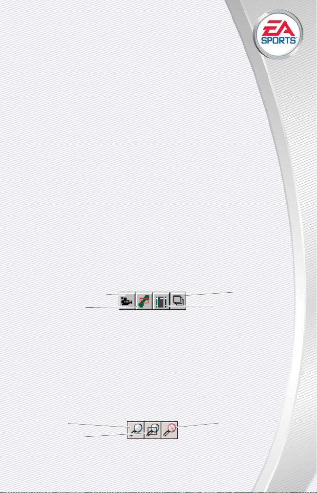
DROP SHAPES
The Drop Shapes button embeds the currently selected floating shapes into the terrain.
When you create a shape in the Course Architect, the shape is initially a
floating shape that rests on top of the terrain. After you have set properties of the shape and its underlying terrain, you can drop the shape into the
terrain, embedding a texture inside the shape into the golf course.
Depending on whether the shape is floating or dropped, you can perform
different functions with it and to it.
✦ For more information, see Right-Click On Floating Shapes on p. 93.
The tools on the Course toolbar are some of the most useful and powerful in developing your projects in the Course Architect. Use these tools to
create new shapes, turn them into hills, bunkers or slopes, populate shapes
and much more.
WINDOW TOOLBAR
From the Window toolbar, you can control the display of the windows in
the Course Architect.
✦ You can toggle display of and arrange the layout of these windows
through the Window menu. For more information, see Window on p. 88.
WINDOW TOOLBAR: LAYERS WINDOW
Click the Layers Window button to display the Layers pop-up.
✦ The Layers window lets you toggle display of objects, sounds, floating
shapes and other course elements to improve performance of the
Course Architect. For more information, see Layers on p. 21.
NAVIGATION TOOLBAR
999911
11
Layers window
Librarian window (see
The Librarian on p. 131)
Camera window (see p. 20)
Navigation window
(see p. 17)
Zoom In
Zoom Select
Cancel Zoom
Page 93

The Navigation toolbar gives you control over the contents of the Work
window. Using these tools, you can zoom in and out over your project or
choose another area of the project to review altogether
.
✦ For more information, see Zoom on p. 70.
NAVIGATION TOOLBAR: ZOOM IN
The Zoom In button changes the view of the Work window so that the
course elements are bigger on the screen.
NAVIGATION TOOLBAR: ZOOM SELECT
The Zoom Select lets you define an area that zooms to exactly fill the
Work window as it is currently sized.
NAVIGATION TOOLBAR: CANCEL ZOOM
The Cancel Zoom button changes the view of the Work window to the
default height and location above the project.
NAVIGATION TOOLBAR: GRAB
The Grab button lets you select a position in the Work window over which
the camera is so moved that the position is in the center of the window.
STATUS BAR
Along the bottom of the Course Architect main window, the status bar is
displayed. It indicates several pieces of information.
➲ To toggle display of the status bar, select STATUS BAR from the View
menu.
POSITION: X, Y, AND Z
As you move the cursor about the Work window, the positional information in the status bar is updated. The information is displayed in terms of Xdirection, Y-direction and Elevation. For more information, see A Note about
3D Directions on p. 23.
➲ To toggle display of measurement in English or metric units, select USE
METRIC in the View menu.
999922
22
Page 94

POINT COUNT
When you position the cursor over a land shape that has
been dropped in the Work window, the point count in the status
bar indicates the total number of points that the object contains.
✦ The point count for a land shape is directly correlated to the memory and
performance capability that it requires. You can reduce the point count
of the land shape without compromising its visual quality by using the
Optimize Detail tool. For more information, see Optimize Detail on p. 143.
✦ You can also select all of the land shapes in your course that have point
counts over a predetermined size. For more information, see Point Count
Indicator on p. 85.
RIGHT-CLICK MENUS
You can access a number of very useful functions by right-clicking on a
shape in the Work or Camera windows.
When you create a shape in the Course Architect, the shape is initially a
floating shape that rests on top of the terrain. After you have set properties of the shape and its underlying terrain, you can drop the shape into the
terrain, embedding a texture of that type into the golf course. Depending
on whether the shape is floating or dropped, you can perform different
functions with it and to it.
✦ For more information on Shapes, see Shapes on p. 105.
RIGHT-CLICK ON FLOATING SHAPES
DELETE
When you right-click on a floating shape, select DELETE to remove it
from the Course Architect.
DUPLICATE
➲ To duplicate a shape, select one in the Work window. Then, right-click
and select DUPLICATE. The highlighted shape is the duplicate.
DROP
➲ To drop a shape into the course, right-click on the shape and select
DROP.
999933
33
Page 95

NOTE:
NOTE:
After a shape has been dropped, you cannot perform further manipulations with it to the underlying terrain. You must pick
up the shape before you can manipulate the terrain again. For
more information, see Right-Click On Dropped Shapes on p. 95.
FLOATING SHAPE PROPERTIES
From the Properties pop-up, you can define the texture and resize the
shape.
➲ To change the texture that appears on top of the shape, select the tex-
ture from the drop-down list.
✦ The name of the library from which the texture came is listed in paren-
theses ( ). The gameplay properties for each texture are defined in the
object library containing that texture. Textures do not appear in the Work
window until the shape is dropped. For more information, see The
Librarian on p. 131.
➲ To resize the shape, select the unit of measurement. Then, use the Up
and Down arrows to choose the value by which you want to inflate or
deflate the shape.
➲ To accept the changes to the shape properties, click OK.
➲ To close the Properties pop-up without accepting changes, click CANCEL.
RIGHT-CLICK ON CONTROL POINTS
You can manipulate a control point of a floating shape by moving it or
through its right-click menu.
✦ A control point is one of the dots that appears when you select a float-
ing shape. These dots can be repositioned, rotated, duplicated or deleted to change the outline of the floating shape.
➲ To move a control point, select the shape in the Work window. Then,
click and drag on the control point to reposition it.
✦ When you select a control point, the icon changes from a pointing finger
to a finger that is pinching the control point.
DELETE
➲ To delete a control point, select the shape in the Work window. Then,
select the control point that you wish to delete and click the right
mouse button. Select DELETE. The control point is deleted.
✦ Deletion of control points can be undone with the Undo command. For
more information, see Undo on p. 68.
999944
44
Page 96

DUPLICATE
➲ To duplicate a control point, select the shape in the Work
window. Then, select the control point nearest the location in
which you want to place the new control point. Click the right
mouse button. Select DUPLICATE. The control point is added
between the source control point and the next one on the shape
in a clockwise direction.
✦ Duplication of control points can be undone with the Undo command.
For more information, see Undo on p. 68.
RIGHT-CLICK ON DROPPED SHAPES
When a shape is dropped into the terrain, it becomes integrated into the
terrain data and therefore has a different set of properties.
DELETE
➲ To delete the dropped shape, right-click on it and then select DELETE.
NOTE:
NOTE:
Objects placed inside of dropped shapes are not deleted.
DELETE WITH CHILDREN
➲ To delete the dropped shape and its child shapes, right-click on it and
then select DELETE WITH CHILDREN.
✦ A child shape is a dropped shape that is completely enclosed by another
shape. So the children of a shape are all of the shapes that are inside of
it. A shape cannot cross over the edge of any other shape.
USE AS A SHAPE
➲ To copy the dropped shape and use it as a floating shape, right-click on
the dropped shape and then select USE AS A SHAPE. The floating shape
is created and selected.
TIP:
TIP:
The Use As a Shape tool is very useful in creating multiple,
similar shapes. After you create one instance of the shape with
which you are satisfied, you can create the remainder of the
shapes of the same type for your course quite easily. Select the
source shape, and then right-click to select USE AS A SHAPE.
Configure properties as needed. For more information, see
Floating Shape Properties on p. 94.
999955
55
Page 97

PICK UP
➲ To remove the shape from the terrain and define it as a floating shape
again, right-click on the dropped shape and then select PICK UP. The
shape is floated and selected.
NOTE:
NOTE:
To reshape the terrain beneath a dropped shape, you
must first pick it up.
PICK UP WITH CHILDREN
➲ To remove the shape and all of its child shapes from the terrain and
define them as floating shapes again, right-click on the dropped parent
shape and then select PICK UP WITH CHILDREN. The shapes are floated
and selected.
NOTE:
NOTE:
To reshape the terrain beneath a dropped shape, you
must first pick it up.
✦ A child shape is a dropped shape that is completely enclosed by another
shape. So the children of a shape are all of the shapes that are inside of
it. A shape cannot cross over the edge of any other shape.
OPTIMIZE DETAIL
During development of a project, multiple elevation operations can be
performed on a single piece of the terrain. The Course Architect adds detail
to represent the multiple manipulations. Some of this data can be removed
NOTE:
NOTE:
If you are experiencing slow performance on compiled
courses, optimize details to remove redundant data. An iterative
process of optimizing detail and compiling to the game several
times over may improve the overall course performance.
It's a good idea to periodically use the Optimize Detail tool to remove the
redundant data in your project file. Using the tool on a regular basis improves
the performance of the course in the Course Architect and in the game.
NOTE:
NOTE:
Optimize Detail is only applicable to the terrain.
999966
66
Page 98

To optimize detail of an area of the project:
1. Until you get a feel for how to optimize your project, you
may want to save a copy of it prior to performing such largescale changes.
➲ To save a copy of your course, select SAVE AS… from the File menu.
2. Move the cursor over a dropped land shape that completely encompass-
es the area in question. In the right corner of the status bar, you can
read the number of points in the shape and all of the shapes inside of
it.
✦ You can get an idea of how much data you will save with Optimize
Detail by right-clicking on the parent shape and selecting PROPERTIES.
For more information, see Dropped Shape Properties on p. 98.
3. When you are ready to optimize the dropped shape or shapes, right-click
on the parent shape and select OPTIMIZE DETAIL.
4. n the pop-up, use the slider bar to indicate the level of optimization that
you require.
NOTE:
NOTE:
Optimize Detail cannot be undone. So, it's best to optimize incrementally. Optimize a little, check it in the Camera window, and then optimize a little more. Even at the lowest setting,
Optimize Detail removes a significant amount of redundancy.
➲ To apply the optimization to the children shapes of the selected shape,
check the appropriate checkbox.
NOTE:
NOTE:
Use the Point Count Indicator in the Tools Menu to find
shapes that with a high point total. For more information, see
Point Count Indicator on p. 85.
5. To begin the optimization as configured, click OK. To cancel and return to
the Course Architect, click CANCEL.
➲ Optimization can take a while to complete, depending on your system.
To cancel optimization during the process, press
s
.
NOTE:
NOTE:
You should remove detail at much higher level for
dropped shapes such as the background texture that encircles the
whole course and objects containing flowerbeds or forests.
6. When the optimization is complete, you should save the course.
999977
77
Page 99

DROPPED SHAPE PROPERTIES
The available Properties of a dropped shape are the same as those of a
floating shape, except that you cannot resize the shape.
➲ To change the texture that appears on top of the shape, select the tex-
ture from the drop-down list.
✦ The name of the library from which the texture came is listed in paren-
theses ( ). The gameplay properties for each texture are defined in the
object library containing that texture. For more information, see The
Librarian on p. 131.
You can also see the possible effects of using the Optimize Detail tool to
reduce the number of points in the shape. For more information, see
Optimize Detail on p. 143.
➲ To apply the changes to all objects of the same type, check the appro-
priate checkbox.
➲ To accept the changes to the shape properties, click OK.
➲ To close the Properties pop-up without accepting changes, click CANCEL.
HOLE DEFINITION
HOLE DEFINITION
When you create a new course in the New Course Wizard, you may not
have the layout of your course finalized. Or, you may decide that your initial
ideas about a hole were unworkable. After you have used the New Course
Wizard, you can define holes in the Course Architect through the Hole
Definition tool.
➲ To open the Hole Definition tool, select HOLE DEFINITION TOOL from the
Tools menu.
✦ You can step through the process of creating a new project and your
first hole through the online tutorial. For more information, see Tutorial:
Creating Hole 1 on p. 45.
999988
88
Green
selected for
current
hole
Define
gallery
locations
Select tees and
shot paths for
those tees
Select pin
positions on
the green
Define Out of
Bounds areas
Instructions
Tee selected
for current
hole
Select hole
number
Page 100

HOLE DEFINITION ELEMENTS
Depending on which gameplay element you are trying to
define within the Hole Definition tool, instructions for how to
define that element are listed at the bottom of the dialog box. With the
Hole Definition tool, you can define the following elements of a hole for
gameplay purposes:
✦ Tees are the locations where golfers begin the hole. Tees are usually set
up and separated based on player ability, with the tees furthest from
the green for Tournament-level players.
✦ Shot paths indicate where computer-controlled golfers should aim for
optimal scoring on the hole.
✦ Pin Positions are potential locations for the pin on the green. You can
place as many pins as you like, and in the game, the location of the pin
for any round is chosen from the set of pin positions.
✦ Out of Bounds areas are defined like shapes to indicate parts of the hole
in which the out of bounds rules of golf apply to balls that land there.
✦ Galleries are areas around the perimeter of the hole where textures of
crowd galleries are placed.
CREATING TEES AND GREENS
Before you define a hole, you need to define the following information:
✦ Size and position of the tee box or boxes.
✦ Size and position of the greens.
✦ Distance between the tees and the greens.
Based upon the distance between the tees and the greens, the par for
the hole is determined. The other elements of the hole, such as sand traps,
water and terrain shapes, can be determined at a later time.
To create a green or tee:
1. From the Tools menu, select CREATE LAND SHAPE. Draw the perimeter
of the shape in the Work window. Right-click to create the floating land
shape (see Create Land Shape on p. 73).
2. Now, the created shape must be identified as a green or tee. Select the
shape in the Work window. Then, right-click and select PROPERTIES.
From the drop-down list, select a Green or Tee texture. Click OK (see
Textures on p. 107).
3. When you are satisfied with the form and position of the shape, its posi-
tion on the terrain, and its relative position and distance from the other
999999
99
 Loading...