


SP2
Pub. 42004-795AQG
GAI-TRONICS® CORPORATION
A HUBBELL COMPANY
SP2 Fiber Handset/Speaker Amplifier Station
Quick Installation Guide
Important Safety Instructions
Read, follow, and retain instructions—All safety and operating instructions should be read and followed before operating
the unit. Retain instructions for future reference.
Heed warnings—Adhere to all warnings on the unit and in the operating instructions.
Attachments—Attachments not recommended by the product manufacturer should not be used, as they may cause
hazards.
Servicing—Do not attempt to service this unit by yourself. Opening or removing covers may expose you to dangerous
voltage or other hazards. Refer all servicing to qualified service personnel.
ATTENTION
international electrical codes. North America—Consult the National Electrical Code (NFPA 70), Canadian Standards
Association (CSA 22.1), and local codes for specific requirements regarding your installation. Clas s 2 circuit wiring must be
performed in accordance with NEC 725.55.
These enclosures must be installed by trained, qualified and competent personnel. Installation must comply with state and
national regulations, as well as safety practices for this type of equip ment.
WARNING
charger without the batteries connected.
In 24 V dc systems, most chargers have an unloaded output of 35 to 45 volts that can quickly damage the equipment designed
for nominal 24 volts. The maximum battery voltage should never exceed the maximum specified input voltage.
WARNING
energized.—Ensure proper grounding to protective earthing.
ATTENTION
component provided by the end installer. Supply voltage 3.3 V dc, supply
current 300 mA, power dissipation 1 W. Fiber optic module must comply
with the provisions of Laser Class 1.
—Install equipment without modification and according to all applicable local, national and
—In 24 V dc systems: Under NO condition sho uld t his equipment be operated fro m a battery
—Do not disconnect equipment while
—This device requires an active laser
General Information
This guide covers the installation of the SP2 Fiber Handset/Speaker
Amplifier Station. Refer to Publication 42004-797L2 for detailed
explanations of the available configuration options and adjustments,
system design information, and warranty information. GAI-Tronics’
product documentation is located on the “Document Center” page of the
GAI-Tronics website. The link to the document center is https://www.gai-
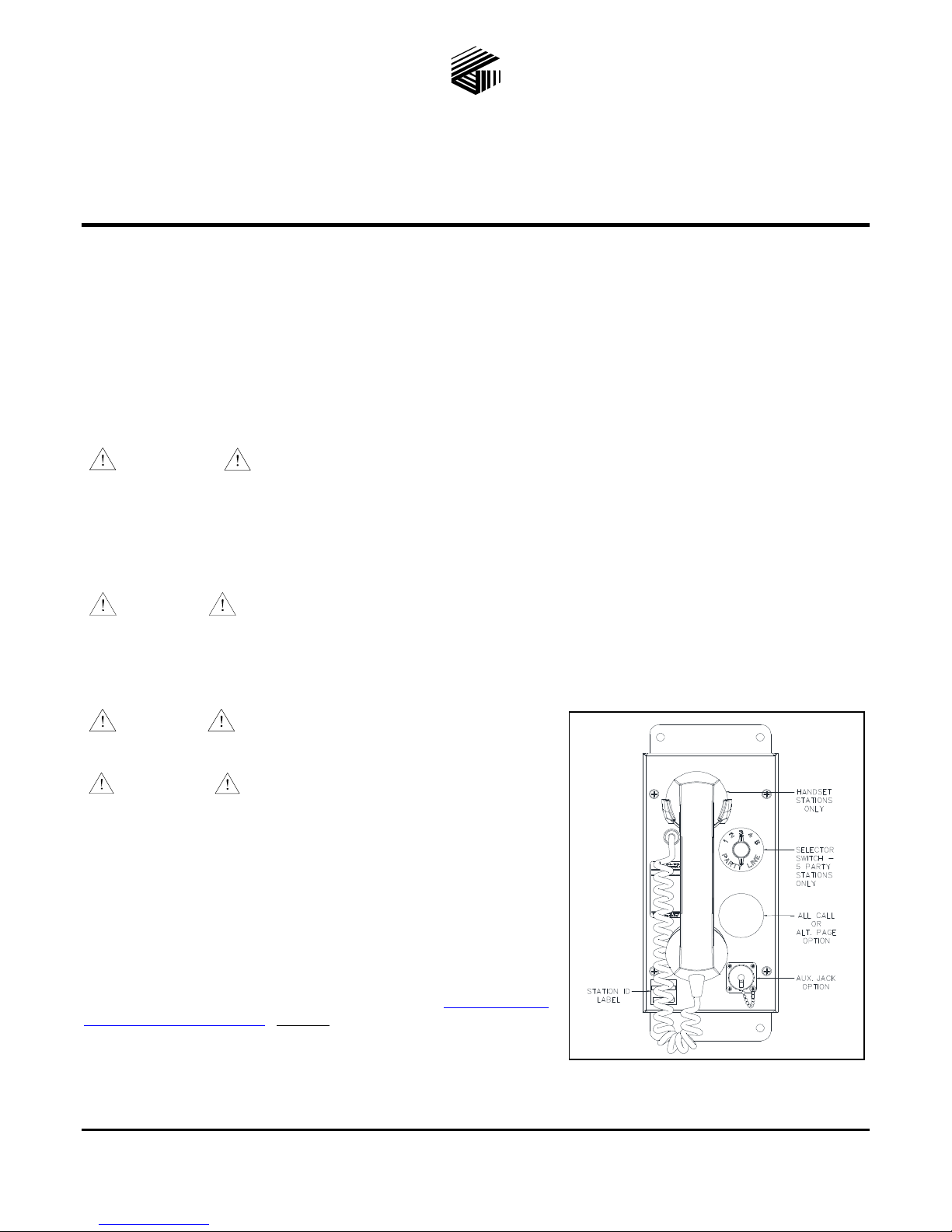
tronics.com/docs/default.htm. Figure 2 shows the standard SP2 Fiber
Handset/Speaker Amplifier Station.
GAI-Tronics Corporation 400 E. Wyomissing Ave. Mohnton, PA 19540 USA
610-777-1374 800-492-1212 Fax: 610-796-5954
ISIT WWW.GAI-TRONICS.COM FOR PRODUCT LITERATURE AND MANUALS
V
Figure 1. SP2 Station
Pub. 42004-795AQG
SP2 Fiber Handset/Speaker Amplifier Station Quick Installation Guide Page 2 of 3
Available Options
70/100V constant voltage termination board
with 24 watt output
24 V dc power supply
speaker/amplifier only (no handset)
headset with page pressbar
five configurable alternate page destinations
with selector switch
All-Call push button
PVC or Hytrel
®
handset cords in 6-, 15-, or
25-foot lengths
conformal PCBA coating
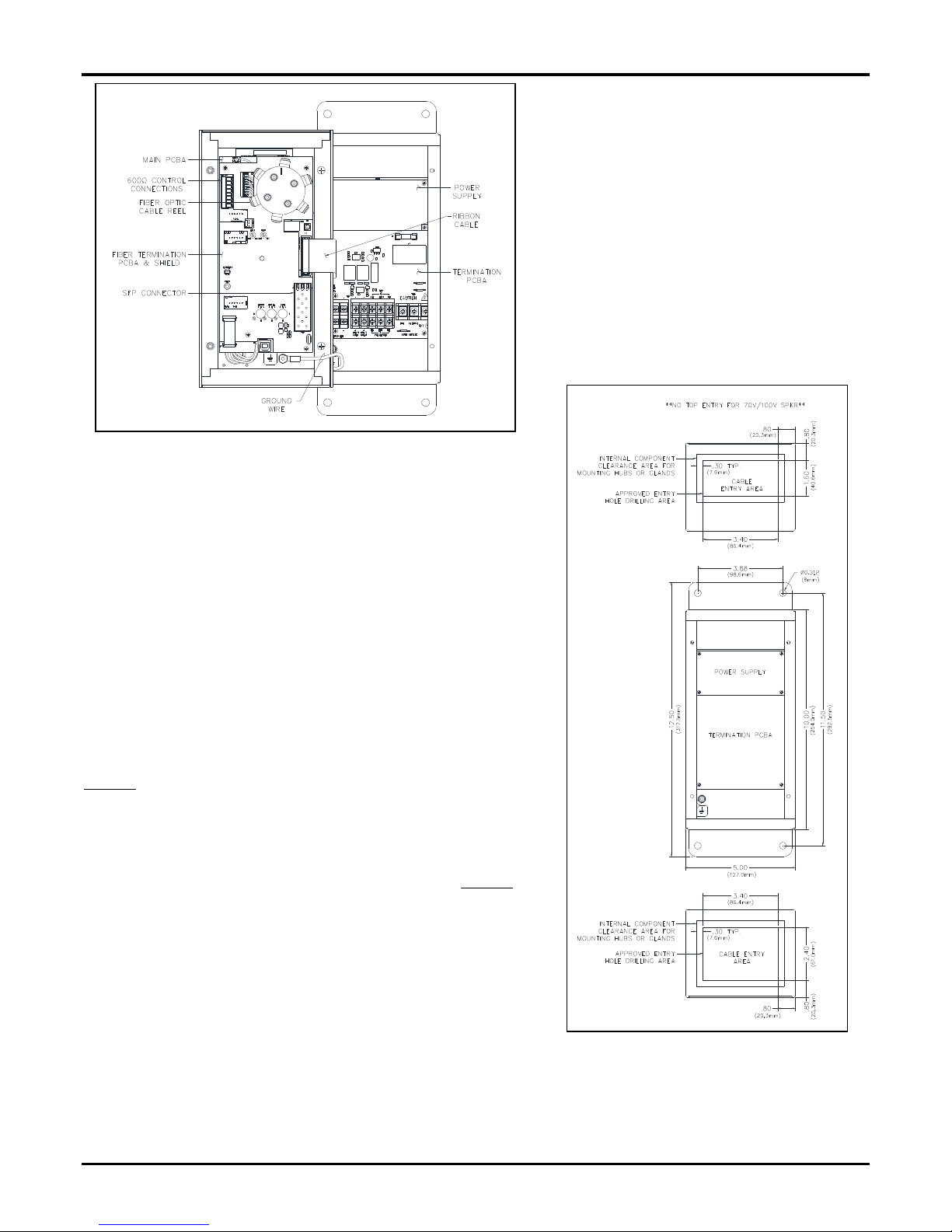
Figure 2. SP2 Station—Interior View
Available Settings and Adjustments
Most optional equipment is preconfigured to default settings at the
factory. The following is a partial list of the available adjustments and
settings that may be needed:
speaker volume series/parallel speaker connection
receiver volume station ID and zone selector.
Installation
Mounting the Enclosure
Mount the enclosure using the four 0.312-inch (8 mm) diameter holes
located on the mounting flanges with ¼-inch (M6) hardware. The
suggested mounting height for all station enclosures is 48 inches (1219
mm) to the center of the bottom mounting holes of the enclosure. See
Figure 3 for mounting details. The SP2 Station is not supplied with
conduit or cable openings.
Remove the front panel and drill or punch entry openings in the rear
section of the enclosure. The station is suitable for bottom and/or top
entry. The recommended entry is via the enclosure bottom to prevent
moisture from dripping onto the termination board. Refer to Figure 3 for
the suggested locations of cable entry. There must be a minimum of ½
inch (13 mm) of material between entry holes.
Field Wiring
The SP2 Station provides terminal blocks on the termination PCBA
located in the rear enclosure for field wiring the power, speaker, and
RTU connections. Connect spade lugs to the wires before fastening
them to the termination board terminal blocks to obtain the most secure
connection. Torque the terminal block screws to 8–10 lb
Nm) when attaching the spade lugs.
The main PCBA, mounted on the back of the front panel, contains the 600-ohm audio connection. Use ferrule terminals for
this connection. The fiber termination board is mounted on top of the main PCBA, which provides fiber optic termination to
the Ethernet SFP transceiver.
P:\Standard IOMs - Current Release\42004-xxxxQG Quick Guides\42004-795AQG.docx
08/17
in (0.90–1.13
Figure 3. Suggested Wire Entry Locations
 Loading...