


Pub. 42004-376C
G A I - T R O N I C S ® C O R P O R A T I O N
A H U B B E L L C O M P A N Y
Model 400-001 and 400-002NS
RigCom Stations
Confidentiality Notice
This manual is provided solely as an operational, installation, and maintenance guide and contains sensitive business and technical information that is confidential and proprietary to GAI-Tronics. GAI-Tronics retains all intellectual property and other rights in or to the information contained herein, and such information may only be used in connection with the operation of your GAI-Tronics product or system. This manual may not be disclosed in any form, in whole or in part, directly or indirectly, to any third party.
General Information
The GAI-Tronics Model 400-001 and 400-002NS RigCom Stations are designed for a common-talk, or master/slave communication system for the following hazardous locations: Model 400-001: Class I, Div. I, Groups C and D; Model 400-002NS: Class I, Div. I, Groups B, C, and D, when installed in accordance with GAI-Tronics Pub. 42004-381, Control Drawing No. 73214. The system provides push-
to-talk, release-to-listen operation, and has a local on/off volume control switch to activate and control the volume level for each station independently.
The Model 400-001 includes an attached speaker and driver unit. The Model 400-002NS does not include the speaker and driver unit, but does have a 1/2-inch NPT hole to remotely mount and connect the speaker driver unit to the station.
The RigCom stations have connections for an auxiliary microphone and footswitch connection for remote operation from the station itself.
In this operation, the auxiliary microphone replaces the speaker as the microphone and the auxiliary footswitch provides the same functionality as the push-to-talk switch. With the use of auxiliary items, the approved hazardous locations are reduced to Class I, Div. I, Group D.
Figure 1. Model 400-001 RigCom Station
GAI-Tronics Corporation 400 E. Wyomissing Ave. Mohnton, PA 19540 USA
610-777-1374 800-492-1212 Fax: 610-796-5954
VISIT WWW.GAI-TRONICS.COM FOR PRODUCT LITERATURE AND MANUALS
|
Pub. 42004-376C |
Model 400-001 and 400-002NS RigCom Stations |
Page 2 of 22 |
The Model 400-001 and 400-002NS RigCom Stations are designed to be field replacements for the previous MS39xx Series RigCom stations. As a field replacement for the MS39xx Series, the Model 400 Series must be configured as an unbalanced station.
Along with operation with the MS39xx Series RigCom stations, the Model 400 Series are designed to operate with the EZ Page Series of GAI-Tronics equipment.
Important Safety Instructions
1.Read, follow, and retain instructions - All safety and operating instructions should be read and followed before operating the unit. Retain instructions for future reference.
2.Heed warnings – adhere to all warnings on the unit and in the operating instructions.
3.Attachments - Attachments not recommended by the product manufacturer should not be used, as they may cause hazards.
4.Servicing - Do not attempt to service this unit yourself. Opening or removing covers may expose you to dangerous voltage or other hazards. Refer all servicing to qualified service personnel.
5.This permanently connected apparatus must have an ALL-POLE MAINS switch with a contact separation of at least 3 mm in each pole incorporated in the electrical installation of the building.
6. WARNING
  To reduce the risk of fire or electrical shock, do not expose this apparatus to rain or moisture.
e:\standard ioms - current release\42004 instr. manuals\42004-376c.doc 04/14

|
Pub. 42004-376C |
Model 400-001 and 400-002NS RigCom Stations |
Page 3 of 22 |
Speaker Horn Assembly (Model 400-001 Only)
After unpacking the unit, locate the speaker horn and the driver unit. The speaker horn assembly must be put together prior to installation.
Place the speaker bell over the driver bushing. Position two large diameter fiber washers with the large diameter steel washer sandwiched between them on the speaker bushing. Place the small diameter rubber washer into the speaker horn tip, followed by the small diameter fiber washer. Screw the speaker horn tip to the driver bushing until it is snug.
Installation
These enclosures must be installed by trained, qualified and competent personnel. Installation must comply with state and national regulations, as well as safety practices for this type of equipment.
Model 400-001 and 400-002NS must be installed in accordance with GAI-Tronics Pub. 42004-381, Control Drawing No. 73214.
CAUTION |
Do not install this equipment in hazardous areas other than those indicated |
|
on the approval listing in the “Specifications” section of this manual. Such installation may cause a safety hazard and consequent injury or property damage.
The mounting location must be flat and provide proper clearance, rigidity and strength to support the enclosure and all contained devices.
Securely fasten the enclosure to the mounting location, using (customer-supplied) 7/16inch diameter steel mounting bolts and washers, or washer head bolts.
 WARNING
Insure proper grounding to protective earthing.
Do not disconnect equipment while energized.
Inspect and clean the machined flange flame joint surfaces of both the cover and box. Surfaces must be smooth, free of nicks, scratches, dirt or any foreign particle build-up that would prevent a proper seal. Surfaces must seat fully against each other to provide a proper explosion-proof joint. Clean surfaces by wiping with a clean lint-free cloth.
Make certain no cover bolts are omitted. Use only those bolts supplied with the enclosure. Recommended torque setting of cover bolts = 17 ft-lbs, (23 N-m)
e:\standard ioms - current release\42004 instr. manuals\42004-376c.doc 04/14
|
Pub. 42004-376C |
Model 400-001 and 400-002NS RigCom Stations |
Page 4 of 22 |
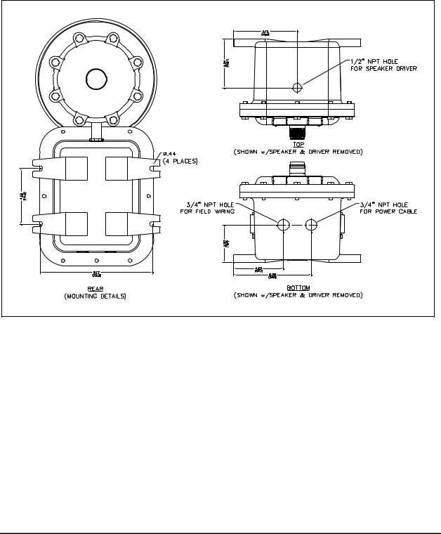
Mounting
NOTE: The mounting surface must be able to support the weight of the aluminum enclosure. See the Specification section for the weights and dimensions of the unit.
The enclosure must be securely fastened with 7/16 -inch diameter steel mounting bolts located on all four mounting feet. Stainless steel hardware is recommended for applications in corrosive environments. Refer to Figure 2 for mounting dimensions.
Figure 2. Model 400-001/400-002NS Mounting Details and Conduit Entries
e:\standard ioms - current release\42004 instr. manuals\42004-376c.doc 04/14
|
Pub. 42004-376C |
Model 400-001 and 400-002NS RigCom Stations |
Page 5 of 22 |
Hardware Configuration
External
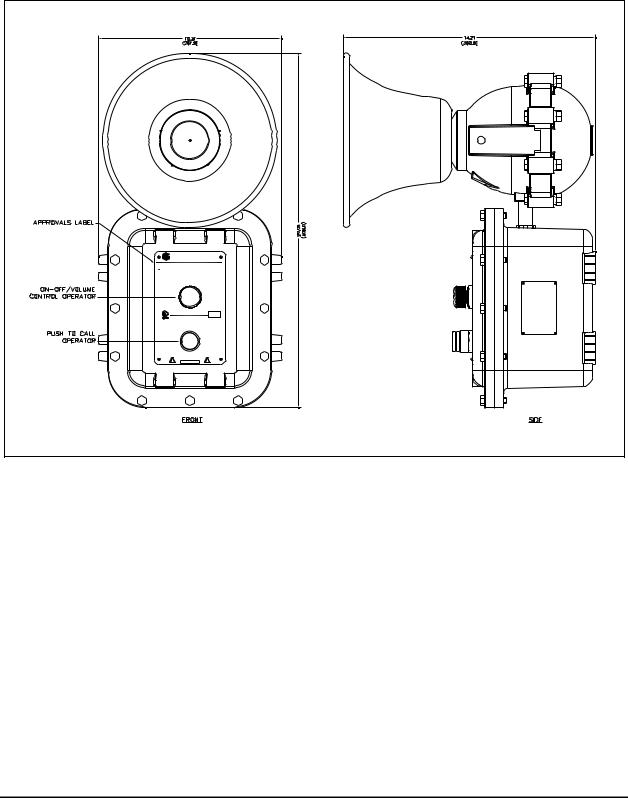
The enclosure contains a push-to-call operator, an on-off/volume control operator and applicable approval labeling. The enclosure itself has 12 cover mounting bolts located around the perimeter of the enclosure.
GAI-TRONICS CORPORATION |
P.O. BOX 1060 READING, PA 19607
SERVICE CENTERS: In USA: 1-800-492-1212 Outside USA: 1-610-777-1374
No. 400-001 - RIGCOM MASTER/SLAVE/COMMON
~ |
120VAC, 50/60 Hz, .400 AMP MAX. OR |
AMBIENT TEMPERATURE: -20°C TO 60°C |
12VDC, 1.8 AMP MAX |
|
WARNING: TO R EDUCE THE RISK OF IGNITION OF HAZARDOUS ATMOSPHERES,
CONDUIT SEALS MUST BE INSTALLED WITHIN 18 INCHES OF ENCLOSURE.
WARNING: EXPLOSION H AZARD - DO NOT DISCONNECT EQUIPMENT UNLESS
POWER HAS BEEN SWITCHED OFF OR THE AREA IS KNOWN TO BE NON-HAZARDOUS.
CAUTION: KEEP COVER TIGHT WHILE CIRCUITS ARE ALIVE.
OFF-ON 
 VOLUME
DATE CODE:
SUITABLE FOR USE IN HAZARDOUS LOCATIONS
CLASS I, DIV. I, GROUPS C, D
NO USER SERVICEABLE PARTS INSIDE.
17R9 REFER SERVICING TO QUALIFIED PERSONNEL ONLY.
PUSH TO CALL
CAUTION
!
Figure 3. Model 400-001 RigCom Station Outline
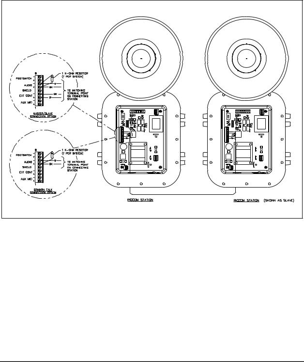
Internal
The enclosure contains a single PCBA where all customer connections are made. All connections are made to the front cover by a single wiring harness with a plug.
e:\standard ioms - current release\42004 instr. manuals\42004-376c.doc 04/14

|
Pub. 42004-376C |
Model 400-001 and 400-002NS RigCom Stations |
Page 6 of 22 |
Wiring
Station Wiring
Attach the conduit or cable glands to the ¾-inch NPT holes on the bottom of the enclosure. Feed the lowvoltage wiring conduit on the left side hole, from front view, and the power wiring through the right side hole, from front view. Attach the wires to the terminal blocks located on the PCBA within the enclosure. See Figure 4 and charts for connection points and descriptions.
If using the 10438-001 Auxiliary Microphone Assembly, connect the assembly to the station at terminal block TB4-1 (+) and TB4-2 (–), shield to TB4-5, if used. The maximum distance from the station is 50 feet using No. 18 AWG wire.
If using the 51052-003 Auxiliary Footswitch Assembly, connect the assembly to the station at terminal block TB4-8 (+) and TB4-9 (–), shield to TB4-5, if used. The maximum distance from the station is 50 feet using No. 18 AWG wire.
Figure 4. RigCom Station PCBA
e:\standard ioms - current release\42004 instr. manuals\42004-376c.doc 04/14
|
Pub. 42004-376C |
Model 400-001 and 400-002NS RigCom Stations |
Page 7 of 22 |
System LineBalance
Each system requires termination of the audio pair wires with the 1 k /1-watt resistor assembly included with each unit. The line balance resistor assembly is made for easy installation into the customersupplied junction box. NOTE: Only one line balance resistor assembly is needed per system.
For cable runs that are approximately 4000 feet (1219 m) or longer, it is recommended that the resistor assembly be installed in a junction box (customer supplied) that is close to the center of the system. Refer to Figure 5 and Figure 6. The junction box must be suitable for the applicable hazardous location in which it is located.
Figure 5. System cable wiring less than 4000 feet in length
e:\standard ioms - current release\42004 instr. manuals\42004-376c.doc 04/14
 Loading...