


Pub. 43004-010H
G A I - T R O N I C S ® C O R P O R A T I O N
A H U B B E L L C O M P A N Y
ITA2000A Series Tone Remote Adapter
with Scanning
User and Installation Manual
*U.S. Patent 6,950,653
GAI-Tronics Corporation 400 E. Wyomissing Ave. Mohnton, PA 19540 USA
610-777-1374 800-492-1212 Fax: 610-796-5954
VISIT WWW.GAI-TRONICS.COM FOR PRODUCT LITERATURE AND MANUALS

CONFIDENTIALITY NOTICE
This manual is provided solely as an operational, installation, and maintenance guide and contains sensitive business and technical information that is confidential and proprietary to GAI-Tronics. GAI-Tronics retains all intellectual property and other rights in or to the information contained herein, and such information may only be used in connection with the operation of your GAI-Tronics product or system. This manual may not be disclosed in any form, in whole or in part, directly or indirectly, to any third party.
COMPUTER SOFTWARE COPYRIGHTS
This product contains copyrighted computer programs stored in semiconductor memory. These programs are copyrighted by GAI-Tronics Corporation and may not be reproduced in any form without express written permission from GAI-Tronics.
WARRANTY
GAI-Tronics warrants for a period of one (1) year from the date of shipment, that any GAI-Tronics equipment supplied hereunder shall be free of defects in material and workmanship, shall comply with the then-current product specifications and product literature, and if applicable, shall be fit for the purpose specified in the agreed-upon quotation or proposal document. If (a) Seller’s goods prove to be defective in workmanship and/or material under normal and proper usage, or unfit for the purpose specified and agreed upon, and (b) Buyer’s claim is made within the warranty period set forth above, Buyer may return such goods to GAI-Tronics’ nearest depot repair facility, freight prepaid, at which time they will be repaired or replaced, at Seller’s option, without charge to Buyer. Repair or replacement shall be Buyer’s sole and exclusive remedy, and the warranty period on any repaired or replacement equipment shall be one (1) year from the date the original equipment was shipped. In no event shall GAI-Tronics’ warranty obligations with respect to equipment exceed 100% of the total cost of the equipment supplied hereunder. The applicability of any such third-party warranty will be determined solely by GAI-Tronics.
Services. Any services GAI-Tronics provides hereunder, whether directly or through subcontractors, shall be performed in accordance with the standard of care with which such services are normally provided in the industry. If the services fail to meet the applicable industry standard, GAI-Tronics will, for a period of one (1) year from the date of completion, re-perform such services at no cost to the Buyer. Re-performance of services shall be Buyer’s sole and exclusive remedy, and in no event shall GAI-Tronics’ warranty obligations with respect to services exceed 100% of the total cost of services provided hereunder.
Limitations/Exclusions. The warranty on any equipment supplied hereunder is subject to Customer’s use in compliance with applicable FCC regulations and manufacturer specifications. The warranties herein shall not apply to, and GAI-Tronics shall not be responsible for, any damage to the goods or failure of the services supplied hereunder, to the extent caused by accident, misuse, abuse, neglect, system design, product modification, failure to follow instructions contained in the product manual, repair, or attempted repair by anyone not authorized by GAI-Tronics, improper installation, installation of parts that do not conform to the quality or specifications of the original parts or accessories, damage or loss occurred during shipment, or any unit which is not new when sold or upon which the serial number has been defaced, modified or removed. The warranty does not extend to damage incurred by natural causes including Force Majeure. The warranty does not cover microprocessors if failure is due to static damage or application of improper voltage. THE WARRANTIES AND REMEDIES CONTAINED HEREIN ARE IN LIEU OF AND EXCLUDE ALL OTHER WARRANTIES AND REMEDIES, WHETHER EXPRESS OR IMPLIED BY OPERATION OF LAW OR OTHERWISE, INCLUDING ANY WARRANTIES OF MERCHANTABILITY OR FITNESS FOR A PARTICULAR PURPOSE.
Operational and Maintenance Procedures. Buyer acknowledges that any improper use, maintenance, or modification of the equipment provided hereunder, or use of unqualified maintenance or service technicians will severely impair the operational effectiveness of the entire communication system. Buyer hereby agrees to indemnify, defend and hold GAITronics harmless from and against any and all third party claims arising, in any manner, out of: (a) Buyer’s neglect of the equipment; (b) Buyer’s use of technicians not authorized by GAI-Tronics to service the equipment; or (c) Buyer’s improper use or modification of the equipment or failure to follow the operational and maintenance procedures provided with the equipment.
Limitation of Liability/Damages. In no event (even should circumstances cause the exclusive warranties and remedies set forth in the Warranty section to fail of their essential purpose) shall either party be liable for any indirect, incidental, special or consequential damages (including, but not limited to, loss of use, loss of anticipated profits, or damages arising from delay) whether such claims are alleged to have arisen out of breach of warranty, breach of contract, strict or absolute liability in tort, or other act, error or omission, or from any other cause whatsoever, or any combination of the foregoing.
Motorola and MAXTRAC are trademarks of Motorola, Inc.
03/13 |
Publication 43004-010H |
i |

Table of Contents
FOREWORD ............................................................................................................................................................... |
1 |
SCOPE OF MANUAL .................................................................................................................................................... |
1 |
NOMENCLATURE ........................................................................................................................................................ |
1 |
ORDERING REPLACEMENT PARTS .............................................................................................................................. |
1 |
SERVICE AND REPAIR ................................................................................................................................................. |
1 |
FCC INTERFERENCE WARNING .................................................................................................................................. |
1 |
SAFE HANDLING OF CMOS INTEGRATED CIRCUIT DEVICES ...................................................................................... |
2 |
DESCRIPTION............................................................................................................................................................ |
3 |
FEATURES AND BENEFITS OF THE ITA2000A TONE REMOTE ADAPTER..................................................................... |
3 |
ADDITIONAL FEATURES AND BENEFITS OF THE ITA2000A TONE REMOTE ADAPTER IN SCAN MODE ....................... |
4 |
PRODUCT OVERVIEW ................................................................................................................................................. |
5 |
ITA2000A ACCESSORIES........................................................................................................................................... |
5 |
SPECIFICATIONS ......................................................................................................................................................... |
6 |
OPERATION ............................................................................................................................................................... |
7 |
FRONT PANEL LED OPERATION................................................................................................................................. |
7 |
PWR LED .......................................................................................................................................................................... |
7 |
PTT LED............................................................................................................................................................................ |
7 |
MON/SCAN LED .............................................................................................................................................................. |
7 |
CSQ LED ........................................................................................................................................................................... |
7 |
ACC PTT LED................................................................................................................................................................... |
7 |
SUPERVISOR LED........................................................................................................................................................... |
7 |
SUPERVISOR BUTTON................................................................................................................................................. |
8 |
DESK MICROPHONE PORT .......................................................................................................................................... |
8 |
Desk Microphone Port Pinout .............................................................................................................................. |
8 |
TONE CONTROL INTERFACE ....................................................................................................................................... |
9 |
Scan Start/Stop in the Scan Mode....................................................................................................................... |
10 |
Radio Monitor in Scan Mode.............................................................................................................................. |
10 |
SUPERVISOR MODE .................................................................................................................................................. |
11 |
ACCESSORY OPERATION .......................................................................................................................................... |
11 |
TEST MODE.............................................................................................................................................................. |
12 |
INSTALLATION....................................................................................................................................................... |
|
13 |
PLANNING THE INSTALLATION.................................................................................................................................. |
|
13 |
MOUNTING............................................................................................................................................................... |
|
13 |
EQUIPMENT REQUIRED............................................................................................................................................. |
|
14 |
Test Equipment ................................................................................................................................................... |
|
14 |
Documentation.................................................................................................................................................... |
|
14 |
CABLE INSTALLATION SAFETY CONSIDERATIONS..................................................................................................... |
|
14 |
TELEPHONE LINE LIGHTNING AND OVER-VOLTAGE PROTECTION............................................................................. |
14 |
|
POWER CONNECTIONS.............................................................................................................................................. |
|
15 |
CONVENTIONAL TO SCANNING OPERATION CONVERSION ........................................................................................ |
16 |
|
RADIO CONNECTOR (J2)........................................................................................................................................... |
|
17 |
Input/Output Radio Connector Table ................................................................................................................. |
|
17 |
ACCESSORY CONNECTOR (J3).................................................................................................................................. |
|
20 |
Input/Output Accessory Connector Table........................................................................................................... |
|
20 |
ITA2000A to Kenwood TK-790/890 Series Radio Connection Chart................................................................. |
21 |
|
ITA2000A to RPG Radio Connection Chart....................................................................................................... |
|
23 |
ITA2000A Tone Remote Adapter to MCS2000 Radio Connection Chart (Conventional Mode Only) ............... |
24 |
|
|
|
|
03/13 |
Publication 43004-010H |
ii |

Table of Contents |
ITA2000A Series Tone Remote Adapter |
|
RADIO TIE LINE (TELEPHONE) CONNECTIONS.......................................................................................................... |
|
25 |
Analog Facility Interface Codes ......................................................................................................................... |
|
25 |
Telephone Line Connection Table ...................................................................................................................... |
|
25 |
JUMPERS .................................................................................................................................................................. |
|
26 |
Jumper Table ...................................................................................................................................................... |
|
26 |
CHANNEL REVERT (CONVENTIONAL MODE ONLY).................................................................................................. |
|
27 |
Channel Revert Settings Table............................................................................................................................ |
|
27 |
CONFIGURATION SWITCH SETTINGS FOR CONVENTIONAL MODE OPERATION .......................................................... |
28 |
|
Switch Settings for SW1 (Conventional) ............................................................................................................. |
|
28 |
Switch Settings for SW2 (Conventional) ............................................................................................................. |
|
29 |
CONFIGURATION SWITCH SETTINGS FOR SCAN MODE OPERATION........................................................................... |
|
30 |
Switch Settings for SW1 (Scan)........................................................................................................................... |
|
30 |
Switch Settings for SW2 (Scan)........................................................................................................................... |
|
31 |
LEVEL SETTINGS AND ADJUSTMENTS....................................................................................................................... |
|
32 |
Receive Audio Level............................................................................................................................................ |
|
32 |
Line Output Level................................................................................................................................................ |
|
32 |
Transmit Audio Level.......................................................................................................................................... |
|
33 |
TEST DIAGNOSTICS .................................................................................................................................................. |
|
34 |
THEORY OF OPERATION .................................................................................................................................... |
|
35 |
TECHNICAL OVERVIEW ............................................................................................................................................ |
|
35 |
Transmit Audio ................................................................................................................................................... |
|
35 |
Radio Audio ........................................................................................................................................................ |
|
35 |
Accessory Transmit............................................................................................................................................. |
|
36 |
Desk Mic Transmit.............................................................................................................................................. |
|
36 |
Reset Circuit ....................................................................................................................................................... |
|
36 |
TROUBLESHOOTING ............................................................................................................................................ |
|
37 |
TROUBLESHOOTING THE ITA2000A TONE REMOTE ADAPTER ................................................................................ |
|
37 |
FUSE REPLACEMENT ................................................................................................................................................ |
|
38 |
MAIN CIRCUIT BOARD ........................................................................................................................................ |
|
39 |
SCHEMATICS .......................................................................................................................................................... |
|
41 |
DEFINITIONS AND ACRONYMS......................................................................................................................... |
|
49 |
03/13 |
Publication 43004-010H |
iii |

Foreword
Scope of Manual
This manual offers descriptive data and service information for the ITA2000A Tone Remote Adapter with Scanning. The unit is shipped as a conventional tone remote adapter but can easily be converted to a scanning tone remote adapter with a simple switch setting change. Please refer to the switch settings located in the Installation section of this manual.
Nomenclature
The model number, located on the nameplate on the bottom, specifically identifies GAI-Tronics equipment. If additional options are ordered, the option will be identified on the circuit board.
Many ITA2000A features are the same in both Conventional and Scan modes. If a feature is particular to either mode, the mode will be identified.
Ordering Replacement Parts
When ordering replacement parts or requesting equipment information, please include the complete identification number. This applies to all components, kits, and chassis. If the component part number is not known, the order should include the number of the chassis or kit of which it is a part and sufficient description of the desired component to identify it. Order parts from:
Customer Service
GAI-Tronics Corporation
400 E. Wyomissing Ave. Mohnton, PA 19540 US: 800-492-1212
Outside US: 610-777-1374
Service and Repair
Inoperative or malfunctioning equipment should be returned to the factory for repair. Please call 1-800-492-1212 to obtain a Return Authorization number, published repair prices, and shipping instructions. A Return Authorization can also be obtained by visiting our website at www.gai-tronics.com.
NOTE: A purchase order or credit card number is required prior to processing non-warranty repairs.
FCC Interference Warning
The FCC requires that manuals pertaining to Class A and Class B computing devices must contain warnings about possible interference with local residential radio and TV reception. This warning reads as follows:
NOTE: This equipment has been tested and found to comply with the limits for a Class A digital device, pursuant to Part 15 of the FCC Rules. These limits are designed to provide reasonable protection against harmful interference when the equipment is operated in a commercial environment. This equipment generates, uses, and can radiate radio frequency energy and, if not installed and used in accordance with the instruction manual, may cause harmful interference to radio communications. Operation of this equipment in a residential area is likely to cause harmful interference in which case the user will be required to correct the interference at his own expense.
1 |
03/13 |
Foreword |
ITA2000A Series Tone Remote Adapter |
Safe Handling of CMOS Integrated Circuit Devices
Many of the integrated circuit devices used in communications equipment are of the Complementary Metal Oxide Semiconductor (CMOS) type. Because of their high open circuit impedance, CMOS integrated circuits are vulnerable to damage from static charges. Care must be taken handling, shipping, and servicing them and the assemblies in which they are used.
Even though protection devices are provided in CMOS integrated circuit inputs, the protection is effective only against overvoltage in the hundreds of volts range such as is encountered in an operating system. In a system, circuit elements distribute static charges and load the CMOS circuits, decreasing the chance of damage. However, CMOS circuits can be damaged by improper handling of the modules, even in a system. To avoid damage to circuits, observe the following handling, shipping, and servicing precautions:
1.Prior to and while servicing a circuit module, particularly after moving within the service area, momentarily touch both hands to a bare metal, earth-grounded surface. This will discharge any static charge that may have accumulated on the person doing the servicing.
NOTE: Wearing a conductive wrist strap will minimize static build-up during servicing.
2.Whenever possible, avoid touching any electrically conductive parts of the circuit module with your hands.
3.Power down the unit before installing or removing the circuit module.
4.When servicing a circuit module, avoid carpeted areas, dry environments, and certain types of clothing (silk, nylon, etc.) because they contribute to static build-up. Similarly, disconnect the test probe prior to removing the ground lead.
5.All electrically powered test equipment should be grounded. Apply the ground lead from the test equipment to the circuit module before connecting the test probe.
6.If a circuit module is removed from the system, it is desirable to lay it on a conductive surface (such as a sheet of aluminum foil) which is connected to ground through 100k of resistance.
7.When soldering, be sure the soldering iron is grounded and has a grounded tip.
8.Prior to connecting jumpers, replacing circuit components, or touching CMOS pins (if this becomes necessary in the replacement of an integrated circuit device), be sure to discharge any static build-up as described in procedure 1. Since voltage differences can exist across the human body, it is recommended that only one hand be used if it is necessary to touch pins on the CMOS device and associated board wiring.
9.When replacing a CMOS integrated circuit device, leave the device in its conductive rail container or conductive foam until it is to be inserted into the printed circuit module.
10.All low impedance test equipment (such as pulse generators, etc.) should be connected to CMOS device inputs after power is applied to the CMOS circuitry. Similarly, such low impedance equipment should be disconnected before power is turned off.
11.Replacement modules shipped separately from the factory will be packaged in a conductive material. Any modules being transported from one area to another should be wrapped in a similar material (aluminum foil may be used). Never use non-conductive material for packaging these modules.
03/13 |
2 |

Description
Features and Benefits of the ITA2000A Tone Remote Adapter
Feature |
Benefit |
|
|
|
|
Adjustable receive input |
Allows flexibility with different radio systems and user |
sensitivity and transmit output |
environments, where radio output levels, line losses, and noise |
level |
factors vary. |
|
|
Autolevel |
Reduces the need for site visits to adjust audio pots. Mobiles |
|
receive consistently high receive sound level, with fewer repeat |
|
requests. |
|
|
Selectable input/output logic |
All inputs/outputs can be individually selected to go active high or |
control |
to ground, depending on the radio, offering compatibility with many |
|
radio systems. |
|
|
Full-duplex capable with 2- or |
With 2-wire capable desk set (such as an ITR2000A), gives full- |
4-wire |
duplex operation for use with most full-duplex and trunking radio |
|
systems. |
|
|
Modular telephone line |
Easy-to-install telephone line cable. |
connection on back |
|
|
|
Selectable timed or continuous |
Flexible monitoring option. |
monitor2 |
|
Multiple parallel desk set support |
System flexibility and productivity are enhanced when several desk |
|
sets are connected. |
|
|
16-channel control1 |
Each of the five-channel steer outputs can be used to change |
|
channels and other functions on certain radios. |
|
|
Courtesy tones |
Sends a tone to the desk set when a mobile has stopped transmitting. |
|
|
Selectable 2175 Hz guard tone |
High and low level guard tones and function tones are sent in |
keying2 |
applications where tones are needed. (e.g. wireless phone line |
|
extension). |
|
|
Supervisor control |
Allows the dispatcher at the ITA2000A to override remote desk sets |
|
and accessory. |
|
|
Front panel mic jack |
Allows dispatch control with desk microphone, headset, handset, |
|
etc. |
|
|
Accessory port |
Allows connection of other devices, such as a local desk set or |
|
telephone interconnect. |
|
|
116-channel control is available only when configured for Conventional mode. When configured for Scan mode, only 15-channel control is available.
2Available only when configured for Conventional mode.
3 |
03/13 |
Description |
ITA2000A Series Tone Remote Adapter |
Additional Features and Benefits of the ITA2000A Tone Remote Adapter in Scan Mode
Feature |
Benefit |
|
|
|
|
Adds scanning capability to |
Enhances radio functionality by using channel steering capability of |
conventional multi-channel |
both non-scanning and scanning radios. Reduces overall system cost. |
radios |
|
|
|
Scanning of up to 15 |
A single multi-channel radio can remotely monitor multiple frequencies, |
frequencies |
reducing the number of radios required for dispatch applications. |
|
|
Allows remote scanning and |
Using regular leased lines, multiple dispatchers can monitor and control |
radio control from multiple |
scanning capability. Each dispatch point displays currently active |
dispatch points |
receive channel. |
|
|
Flexible scanning |
Number of channels, scan rate, scan-stop time, and scan resume can all |
configuration |
be easily configured using readily accessible DIP switches. |
|
|
Talk-back scanning |
Allows dispatcher to transmit on last active receive channel. |
|
|
Remote scan on/off |
Scanning can be remotely turned on or off. Properly equipped parallel |
|
dispatch devices are updated with the status. |
|
|
15-channel control |
Each of the five channel steer outputs can be used to change channels |
|
and other functions on certain radios. |
|
|
03/13 |
4 |
ITA2000A Series Tone Remote Adapter |
Description |
Product Overview
The ITA2000A Tone Remote Adapter uses a state-of-the-art digital signal processor (DSP) to ensure highly accurate and fast tone encoding/decoding and audio filtering. It allows a radio to be remotely controlled through dedicated, leased telephone lines or in-house wiring using standard EIA tone keying sequences.
The advantages include flexible configuration, front panel controls and status indicators for set-up convenience, automatic level control (ALC), and a dispatcher/service mic jack. It is compact, measuring 7.03 W 6.3 L 1.5 H inches, and supports full-duplex or simplex, 2- or 4-wire desk set stations. The ITA2000A has an accessory connector that supports local control devices, such as a telephone interconnect, extended local desk set, or a secondary radio.
Using GAI-Tronics’ ITR2000A or IPE2500A Tone Remote Desk Set, the ITA2000A programmed for Scan mode (using patented techniques), adds tone remote scanning and scan start/stop capability to conventional, multi-channel, steering-capable radios. Dispatch points are updated using these techniques through the use of the parallel status update feature found in the GAI-Tronics Model ITR2000A and IPE2500A Desk Sets.
To accommodate radios that vary in their active input logic, the ITA2000A can be set up to provide discrete active output logic functions. Active low or active high outputs can be set for each radio and accessory Channel Selection Output, Monitor, Push-to-Talk, Push-to-Talk Sense, and CSQ Detect.
ITA2000A Accessories
Description |
Part No. |
|
|
|
|
GM300/MAXTRAC or Motorola GR1225 Radio Interface Cable |
61531-007 |
|
|
Kenwood Radio Interface Cable (KCT-19) |
61531-004 |
|
|
Radio Interface Cable (bare leads), 3-foot (included with unit) |
97C160-0003 |
|
|
Power Supply, 100-240 V ac/12 V dc1 |
40419-008 |
Power Supply Adapter, European |
40420-001 |
|
|
Power Supply Adapter, UK |
40420-002 |
|
|
Power Supply Adapter, Australia |
40420-003 |
|
|
Power Supply Adapter, Korea |
40420-004 |
|
|
Fuse, F2, (Telco line only) Bussmann C515S 1.25A |
4612-23015-25 |
|
|
Fuse, F1, (Power) Bussmann Type GMA-1A |
4612-23500-01 |
|
|
Dual 19-inch Rack Mount, 1.75-inch high (Can hold two ITA2000A |
XAC0005A |
units.) |
|
|
|
1Power (12 V dc) may be obtained directly from the controlled radio. A local power supply, if required, must be ordered separately.
5 |
03/13 |

Description ITA2000A Series Tone Remote Adapter
Specifications
Color ...................................................................................................................................................... |
|
|
|
|
|
|
|
|
|
|
|
|
Black |
|
Physical size................................................................................................... |
|
|
|
|
|
|
|
|
7.03 W 6.3 L 1.5 H inches |
|||||
Weight.................................................................................................................................................... |
|
|
|
|
|
|
|
|
|
|
|
|
4 lbs. |
|
Temperature range ................................................................................................................. |
|
|
|
|
|
|
|
|
|
−30º C to 70º C |
||||
Humidity .................................................................................................................................... |
|
|
|
|
|
|
|
|
|
|
|
95% at 50º C |
||
Input power (main or aux.) |
.................................................................... |
|
|
|
|
|
|
10.5 to 16 V dc; 100 mA maximum |
||||||
Frequency response............................ |
|
|
+3 dB, 300 to 3000 Hz (except TX and RX audio notch at 2175 Hz) |
|||||||||||
Hum and noise ..................................................................................... |
|
|
|
|
|
|
More than -45 dB below rated output |
|||||||
Line audio input........................... |
|
Microprocessor automatically compensates for line loses of up to 24 dB |
||||||||||||
Audio distortion ............................................................................................................... |
|
|
|
|
|
|
|
|
|
Less than 3% THD |
||||
RX input............................................................. |
|
|
|
|
|
32 mV ac to 4.5 V ac into 600 ohms (nominal 300 mV ac) |
||||||||
TX input........................................................... |
|
|
|
|
|
32 mV ac to 800 mV ac into 600 ohms (nominal 80 mV ac) |
||||||||
Line input |
........................................................... |
|
|
|
|
−25 dBm to 0 dBm AGC to reference (nominal −10 dBm) |
||||||||
Line output......................................... |
|
|
−15 dBm to +10 dBm adjustable into 600 ohms (nominal −10 dBm) |
|||||||||||
Logic outputs ........................................................................ |
|
|
|
|
|
PTT, CH-STEER; 20 mA, 100 mW dissipated |
||||||||
Maximum number of desk sets supported (practical limit) |
........................................................................ |
|
|
|
10 |
|||||||||
Microphone connections..................................................................................................... |
|
|
|
|
|
|
|
|
|
Desk microphone |
||||
Input tone tolerance ................................................................................................................................. |
|
|
|
|
|
|
|
|
|
+2% |
||||
Safety .................................................................................................... |
|
|
|
|
|
|
|
|
Class III SELV powered equipment. |
|||||
|
|
|
|
|
|
|
|
|
|
Powered by optional UL-listed (E104603) |
||||
|
|
|
|
|
|
|
|
|
|
and CSA certified (LR67888) ac adapter. |
||||
EMI ................................................................................................. |
|
|
|
|
|
|
|
|
USA: FCC Part 15, Sub. B-Verification |
|||||
|
|
|
|
|
|
|
|
|
|
|
|
|
Canada: ICES-003 |
|
Line Interface......................................................................... |
|
|
|
|
|
|
FCC Part 68 Exempt (Category II Tariff #260 |
|||||||
|
|
|
|
|
|
|
|
|
|
service for private/leased line applications) |
||||
|
|
|
|
|
|
|
|
|
IC: Designed to meet CS03-8. (Cert. Pending) |
|||||
|
|
|
|
|
|
|
Category: Voice-band metallic private line channel interface. |
|||||||
|
|
|
|
|
|
|
|
|
|
|
|
|
|
|
F1 |
|
1950 Hz |
|
F5 |
|
1550 Hz |
|
F9 |
|
1150 Hz |
|
F13 |
|
750 Hz |
|
|
|
|
|
|
|
|
|
|
|
|
|
|
|
F2 |
|
1850 Hz |
|
F6 |
|
1450 Hz |
|
F10 |
|
1050 Hz |
|
F14 |
|
650 Hz |
|
|
|
|
|
|
|
|
|
|
|
|
|
|
|
F3 |
|
1750 Hz |
|
F7 |
|
1350 Hz |
|
F11 |
|
950 Hz |
|
F15 |
|
550 Hz |
|
|
|
|
|
|
|
|
|
|
|
|
Scan Start/Stop1 |
|
|
F4 |
|
1650 Hz |
|
F8 |
|
1250 Hz |
|
F12 |
|
850 Hz |
|
|
||
|
|
|
|
|
|
|
|
|
|
|
|
or, |
|
2050 Hz |
|
|
|
|
|
|
|
|
|
|
|
|
Monitor/F162 |
|
|
1Scan operation only
2Conventional operation only - Monitor/F16 is switch-selectable. See the programmable switch settings in the “Installation” section of this manual.
03/13 |
6 |
Operation
Front Panel LED Operation
ITA2000 |
Front View of the ITA2000A
PWR LED
The PWR LED illuminates to indicate that the ITA2000A power is on and the DSP is operating.
PTT LED
The push-to-talk LED, labeled PTT, illuminates when a valid transmit request has been decoded or the mic PTT is actuated.
MON/SCAN LED
Conventional: The timed or constant monitor LED, labeled MON, illuminates when the ITA2000A is in the monitor mode.
Scan: The SCAN LED blinks at the scan rate when the ITA2000A is scanning, and is lit steadily when in monitor mode.
CSQ LED
The CSQ LED illuminates when a carrier detect input is active.
ACC PTT LED
The ACC PTT LED illuminates when the accessory PTT input is active.
SUPERVISOR LED
The SUPERVISOR LED illuminates when the ITA2000A is placed into supervisor mode.
7 |
03/13 |

Operation |
ITA2000A Series Tone Remote Adapter |
Supervisor Button
The SUPERVISOR button with the associated LED indicator provide full dispatcher control of the radio system. This button is used to enter the supervisor mode or the test mode. Refer to the Operation section for more information.
Desk Microphone Port
The front panel desk microphone port (MIC), is an 8-pin modular connector that supports an external connection for local dispatch control. (Possible accessories include desk, gooseneck, or boom microphones, or a headset or footswitch via the GAI-Tronics XAAB002A Audio Accessory Box).
Audio from this microphone is routed to the station transmit and receive audio and the telephone line while push-to-talk is applied from the external microphone. The front-panel mic audio does not have a guard tone notch applied. Station receive audio is also provided at the MIC connector. This feature allows a handset or similar device to be used in place of a desk microphone.
An external microphone monitor function places the ITA2000A in the monitor mode while asserting PL/DPL disable at the radio connector. The microphone input type is passive, with an input impedance of less than 2 k and a nominal input level of −20 dBm. The GAI-Tronics XDM004A Desk Microphone is an acceptable example.
DeskMicrophonePort Pinout |
|
|
|
|
|
|
|
|
|
|
|
|
||
|
|
|
|
|
|
|
|
|
|
|
|
|
|
|
|
Pin No. |
Function |
|
|
|
|
|
|
|
|
|
|
|
|
|
|
|
|
|
|
|
|
|
|
|
|
|
|
|
|
|
|
|
|
|
|
|
|
|
|
|
|
|
|
|
1 |
B+ OUT (through 10 ohms) |
|
|
|
|
|
|
|
|
|
|
|
|
|
|
|
|
|
|
|
|
|
|
|
|
|
|
|
|
2 |
N/C |
|
|
|
|
|
|
|
|
|
|
|
|
|
|
|
|
|
|
|
|
|
|
|
|
|
|
|
|
3 |
Monitor IN (closure to ground) |
|
|
|
|
|
|
|
|
|
|
|
|
|
|
|
|
|
|
|
|
|
|
|
|
|
||
|
4 |
AGND |
|
|
|
|
|
|
|
|
|
|
|
|
|
|
|
|
|
|
|
|
|
|
|
|
|
||
|
|
|
|
|
|
|
|
|
|
|
|
|
||
|
|
|
|
|
|
|
|
|
|
|
|
|
|
|
|
5 |
Mic IN (with bias voltage) |
|
|
|
|
|
|
|
|
|
|
|
|
|
|
|
|
|
|
|
|
|
|
|
|
|
|
|
|
6 |
PTT IN (closure to ground) |
|
|
|
|
|
|
|
|
|
|
|
|
|
|
|
|
|
||||||||||
|
7 |
N/C |
|
Desk Mic Port Pinout |
||||||||||
|
|
|
|
|
|
|
|
|
|
|
|
|
|
|
|
8 |
RX audio OUT (handset audio) |
|
|
|
|
|
|
|
|
|
|
|
|
|
|
|
|
|
|
|
|
|
|
|
|
|
|
|
03/13 |
8 |
ITA2000A Series Tone Remote Adapter |
Operation |
The rear view of the ITA2000A shows the line, accessory, radio, and power connector locations. Also shown are the TX and RX level adjustment pots, and the location of the internal fuse.
LINE |
ACCESSORY |
|
|
|
DC POWER |
RADIO |
LEVEL |
|
|||
|
|
||||
|
|
|
|
||
|
|
|
TX |
RX |
13.8VDC |
|
|
|
|
|
0.3A |
|
|
|
|
|
INTERNAL |
|
|
|
|
|
FUSE |
Rear View of the ITA2000A
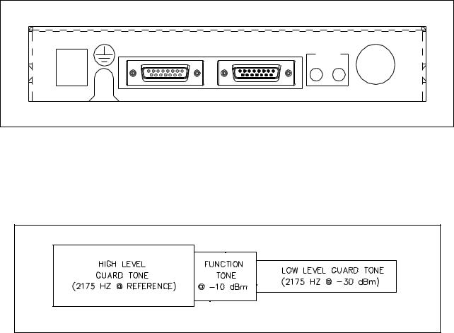
Tone Control Interface
The ITA2000A decodes standard EIA tone keying control tones for controlling the radio system. The control tone convention can be seen below.
Standard EIA Tone Control Sequence
The function tone frequency ranges from 550 Hz to 2050 Hz in 100 Hz increments. 2050 Hz represents monitor in Conventional mode and scan start/stop in Scan mode, 1950 Hz for F1, 1850 Hz for F2 down to 550 Hz for F15.
When scanning and carrier is detected, a similar tone sequence is generated to the phone line where HLGT is generated for 40 ms followed by a 20 ms function tone representative of the current channel. This tone sequence will be decoded by desk sets capable of fast parallel status update, such as the GAITronics ITR2000A and IPE2500A. The use of products that are not capable of decoding this fast tone sequence is not advisable, as the reliability of the operator information may be less than desirable.
9 |
03/13 |
Operation |
ITA2000A Series Tone Remote Adapter |
ScanStart/StopintheScanMode
Upon power-up, the ITA2000A will automatically start scanning. While in scan mode, the ITA2000A asserts, in sequence, the channel steer pins at the configured scan rate. Upon detection of carrier, the unit stops scan and generates the appropriate tone sequence to the phone line. Upon loss of carrier, the unit resumes scan after the configured scan stop time, or until manually started by that attached desk set, depending on the configuration of the unit. When the unit resumes scan, a monitor function tone burst is generated indicating to the attached desk sets that scan has resumed. If the operator wishes to stop the scan resume before the scan stop time expires, the scan should be stopped using the scan stop feature.
The ITA2000A supports a remote scan start/stop toggle feature via the monitor function tone or 2050 Hz. Pressing the desk set MONITOR button causes a 2050 Hz tone sequence to be generated. When in scan mode, if a valid 2050 Hz tone sequence is decoded, the unit stops scan on the current scan channel and generates a tone burst to the phone line indicating to the attached desk set(s) the channel on which the scan was stopped.
Likewise, when not in scan mode, if a valid 2050 Hz tone sequence is detected, the unit will resume scan. The decoding of this 2050 Hz tone sequence by parallel desk sets indicates that scan has been resumed. While in scan mode, if a channel steer is done by the desk set, the unit will cease scan. If the unit is configured to resume scan after PTT, the unit will do so after the first PTT from the desk set. If the operator wishes to remain on the channel indefinitely, scan must be stopped prior to issuing the channel steer.
RadioMonitor inScanMode
The ITA2000A does not use a monitor function tone for assertion of monitor that may be required in some installations, when in scan mode. To place the ITA2000A into monitor mode, the desk set must force a channel steer to the desired channel by generating the appropriate function tone burst. This causes the ITA2000A to stop scan and assert the PL/DPL disable output to the radio placing the radio in monitor mode. When in this mode, the SCAN LED is lit. Subsequent transmissions by the desk set will cause this assertion to be cleared until the desk set, again, generates an appropriate function tone burst.
An example of this operation using an IPE2500A Tone Remote Desk Set is as follows:
1.While scanning, the desk set operator wishes to transmit on channel 3. Before doing so, the operator must ensure that the channel is clear by placing the radio in monitor mode on channel 3. The operator presses the “3” key on the IPE25000A causing the desk set to generate a tone burst consisting of HLGT followed by a function tone of 1750 Hz. Note that no low-level guard tone is generated. The ITA2000A stops scan, switches to channel 3, asserts the PL/DPL output placing the radio in monitor mode, and lights the SCAN LED.
2.The operator monitors the channel for activity and, upon assuring there is none, presses the TRANSMIT key on the IPE2500A. The desk set generates a tone burst of HLGT followed by a function tone of 1750 Hz, which is followed by LLGT. The ITA2000A asserts the radio PTT, clears the assertion of the PL/DPL output and extinguishes the SCAN LED.
3.The operator releases the TRANSMIT key on the IPE2500A and the ITA2000A releases PTT from the radio. The ITA2000A does not reassert the PL/DPL output to the radio. The operator carries on a conversation with the field unit normally. If the unit is configured to resume scan after PTT, the unit will do so after the scan-stop time has passed upon releasing PTT unless scan was halted prior to the transmission.
4.If the operator wishes to again place the radio in monitor mode on channel 3, he must press the “3” key again. The ITA2000A will decode the tone burst and place the radio into monitor mode as in number 1 above.
03/13 |
10 |
ITA2000A Series Tone Remote Adapter |
Operation |
Supervisor Mode
The ITA2000A is placed in the supervisor mode by pressing the SUPERVISOR button for less than four seconds, or by pressing either the MONITOR or PTT buttons of an attached desk-mic accessory. This feature can be disabled in Conventional mode. When supervisor mode is entered, the SUPERVISOR LED illuminates and the ITA2000A enters home-mode state. This is useful when a dispatcher needs to disable control of the radio from all desk set operators and the accessory input. Pressing the SUPERVISOR button again for less than four seconds is the only method used to exit supervisor mode and return the ITA2000A to normal operation.
In the home-mode state, the ITA2000A clears all channel steer lines to the radio and generates continuous guard tone to the phone line. In addition, the ITA2000A ceases scanning if in Scan mode. The generation of guard tone serves two purposes. First, all LOTL-equipped desk sets such as the ITR2000A or IPE2500A connected to the ITA2000A will recognize the base station is now in use and will effectively lock out any operations. Second, when using the Scan mode, the generation of the guard tone will clear the scan (monitor) indicator of these connected desk sets indicating that scan has stopped.
When home-mode is exited, the ITA2000A returns to the previously selected channel, or if in Scan mode, returns to the previous scan state. If scan were active prior to entering the home-mode state, the ITA2000A returns to scan upon exiting home-mode state and generates a tone burst to the phone line to update the connected desk sets appropriately. If scan were not active prior to entering home-mode state, the ITA2000A will not resume scan upon exiting home-mode state.
Accessory Operation
The ITA2000A includes an accessory connector to allow access to the radio from other devices such as an ILD1000A Local Control Desk Set, a PL1877A Telephone Interconnect, or an additional ITA2000. With such devices, control of the radio is limited to monitor and PTT. When an accessory device requires access to the radio, it will assert the appropriate input on the accessory connector. When this assertion is detected, the ITA2000A enters home-mode state. This feature can be disabled when in Conventional mode.
When an accessory asserts the accessory monitor input, the ITA2000A enters home-mode state. When the accessory releases the accessory monitor input, the ITA2000A exits home-mode state. If in Scan mode, the ITA2000A resumes scan after the scan stop time if scan were active prior to the assertion of the accessory monitor input.
When the accessory asserts the accessory PTT input, the ITA2000A enters home-mode state for the duration of the assertion when in Scan mode. When the accessory releases the accessory PTT input, Conventional mode exits home-mode state, and Scan mode immediately returns to the previous scan state.
11 |
03/13 |
Operation |
ITA2000A Series Tone Remote Adapter |
Test Mode
To enter the test mode, press the SUPERVISOR button for more than four seconds. All LEDs illuminate for two seconds indicating the ITA2000A has entered the test mode.
While the ITA2000A is in test mode, pressing the SUPERVISOR button momentarily (less than four seconds) causes the ITA2000A to step up to the next test.
 WARNING
Disconnect the ITA2000A from the radio and disconnect all accessories from the ITA2000A when performing Diagnostic Tests 2, 3, and 4. These diagnostics are used for factory testing only and perform input/output configuration tests that may damage the interface to the radio and/or any accessories connected to the ITA2000A.
Pressing the button again for at least four seconds takes the ITA2000A out of the test mode.
03/13 |
12 |

Installation
Planning the Installation
Typical ITA2000A Installation
Mounting
The ITA2000A Tone Remote Adapter can be installed in a customer-supplied rack or cabinet, or can be placed on a desk for convenience when used with microphones and other accessories. A 19-inch standard rack panel, 1.75 inches high, is also available. The GAI-Tronics part number is XAC0005A.
13 |
03/13 |
 Loading...