


Pub. 43004-008H
GAI-TRONICS® CORPORATION
A HUBBELL COMPANY
IPE2500A and IPE2500A-MLS
Paging Encoder/Desktop Controller
User and Installation Manual
GAI-Tronics Corporation 400 E. Wyomissing Ave. Mohnton, PA 19540 USA
610-777-1374 800-492-1212 Fax: 610-796-5954
ISIT WWW.GAI-TRONICS.COM FOR PRODUCT LITERATURE AND MANUALS
V

CONFIDENTIALITY NOTICE
This manual is provided solely as an operational, installation, and maintenance guide and contains
sensitive business and technical information that is confidential and proprietary to GAI-Tronics.
GAI-Tronics retains all intellectual property and other rights in or to the information contained herein,
and such information may only be used in connection with the operation of your GAI-Tronics product or
system. This manual may not be disclosed in any form, in whole or in part, directly or indirectly, to any
third party.
COMPUTER SOFTWARE COPYRIGHTS
This product contains copyrighted computer programs stored in semiconductor memory. These programs
are copyrighted by GAI-Tronics Corporation and may not be reproduced in any form without express
written permission from GAI-Tronics.
WARRANTY
GAI-Tronics warrants for a period of one (1) year from the date of shipment, that any GAI-Tronics equipment supplied hereunder
shall be free of defects in material and workmanship, shall comply with the then-current product specifications and product
literature, and if applicable, shall be fit for the purpose specified in the agreed-upon quotation or proposal document. If (a)
Seller’s goods prove to be defective in workmanship and/or material under normal and proper usage, or unfit for the purpose
specified and agreed upon, and (b) Buyer’s claim is made within the warranty period set forth above, Buyer may return such
goods to GAI-Tronics’ nearest depot repair facility, freight prepaid, at which time they will be repaired or replaced, at Seller’s
option, without charge to Buyer. Repair or replacement shall be Buyer’s sole and exclusive remedy, and the warranty period on
any repaired or replacement equipment shall be one (1) year from the date the original equipment was shipped. In no event shall
GAI-Tronics’ warranty obligations with respect to equipment exceed 100% of the total cost of the equipment supplied hereunder.
The applicability of any such third-party warranty will be determined solely by GAI-Tronics.
Services. Any services GAI-Tronics provides hereunder, whether directly or through subcontractors, shall be performed in
accordance with the standard of care with which such services are normally provided in the industry. If the services fail to meet
the applicable industry standard, GAI-Tronics will, for a period of one (1) year from the date of completion, re-perform such
services at no cost to the Buyer. Re-performance of services shall be Buyer’s sole and exclusive remedy, and in no event shall
GAI-Tronics’ warranty obligations with respect to services exceed 100% of the total cost of services provided hereunder.
Limitations/Exclusions. The warranty on any equipment supplied hereunder is subject to Customer’s use in compliance
with applicable FCC regulations and manufacturer specifications. The warranties herein shall not apply to, and GAI-Tronics
shall not be responsible for, any damage to the goods or failure of the services supplied hereunder, to the extent caused by
accident, misuse, abuse, neglect, system design, product modification, failure to follow instructions contained in the product
manual, repair, or attempted repair by anyone not authorized by GAI-Tronics, improper installation, installation of parts that do
not conform to the quality or specifications of the original parts or accessories, damage or loss occurred during shipment, or any
unit which is not new when sold or upon which the serial number has been defaced, modified or removed. The warranty does not
extend to damage incurred by natural causes including Force Majeure. The warranty does not cover microprocessors if failure is
due to static damage or application of improper voltage.
THE WARRANTIES AND REMEDIES CONTAINED
HEREIN ARE IN LIEU OF AND EXCLUDE ALL OTHER WARRANTIES AND REMEDIES, WHETHER
EXPRESS OR IMPLIED BY OPERATION OF LAW OR OTHERWISE, INCLUDING ANY WARRANTIES OF
MERCHANTABILITY OR FITNESS FOR A PARTICULAR PURPOSE.
Operational and Maintenance Procedures. Buyer acknowledges that any improper use, maintenance, or
modification of the equipment provided hereunder, or use of unqualified maintenance or service technicians will severely impair
the operational effectiveness of the entire communication system. Buyer hereby agrees to indemnify, defend and hold GAITronics harmless from and against any and all third party claims arising, in any manner, out of: (a) Buyer’s neglect of the
equipment; (b) Buyer’s use of technicians not authorized by GAI-Tronics to service the equipment; or (c) Buyer’s improper use
or modification of the equipment or failure to follow the operational and maintenance procedures provided with the equipment.
Limitation of Liability/Damages. In no event (even should circumstances cause the exclusive warranties and remedies
set forth in the Warranty section to fail of their essential purpose) shall either party be liable for any indirect, incidental, special
or consequential damages (including, but not limited to, loss of use, loss of anticipated profits, or damages arising from delay)
whether such claims are alleged to have arisen out of breach of warranty, breach of contract, strict or absolute liability in tort, or
other act, error or omission, or from any other cause whatsoever, or any combination of the foregoing.
03/12 Pub. 43004-008H ii

Table of Contents
FOREWORD ............................................................................................................................................................... 1
SCOPE OF MANUAL .................................................................................................................................................... 1
NOMENCLATURE ........................................................................................................................................................ 1
ORDERING REPLACEMENT PARTS .............................................................................................................................. 1
SERVICE AND REPAIR ................................................................................................................................................. 1
FCC INTERFERENCE WARNING .................................................................................................................................. 1
SAFE HANDLING OF CMOS INTEGRATED CIRCUIT DEVICES ...................................................................................... 2
DESCRIPTION............................................................................................................................................................ 3
FEATURES AND BENEFITS ........................................................................................................................................... 3
INTRODUCTION TO THE IPE2500A PAGING ENCODER/DESKTOP CONTROLLER .......................................................... 4
DESK SET BUTTON PANEL ......................................................................................................................................... 5
INTERNAL MICROPHONE AND SPEAKER ..................................................................................................................... 6
HANDSET ................................................................................................................................................................... 6
CONNECTORS ............................................................................................................................................................. 6
Power Connector .................................................................................................................................................. 6
Line Connector ..................................................................................................................................................... 7
Audio Accessory/RS-232 Port ............................................................................................................................... 7
CONTROL TONES ........................................................................................................................................................ 8
TONE LEVELS ............................................................................................................................................................. 8
DTMF DECODE/H.E.A.R. SYSTEM SUPPORT ............................................................................................................. 8
ACCESSORIES ............................................................................................................................................................. 9
FIELD REPLACEMENT ITEMS ...................................................................................................................................... 9
PROGRAMMING .......................................................................................................................................................... 9
PERFORMANCE SPECIFICATIONS ............................................................................................................................... 10
OPERATION ............................................................................................................................................................. 11
DISPLAY ................................................................................................................................................................... 11
RECEIVING CALLS .................................................................................................................................................... 12
INITIATING CALLS .................................................................................................................................................... 12
Handset Transmit ................................................................................................................................................ 13
Transmit From Internal (Local) Microphone ..................................................................................................... 13
Transmit From Desk Microphone or Footswitch ................................................................................................ 13
FRONT PANEL BUTTONS ........................................................................................................................................... 14
Signaling Buttons ................................................................................................................................................ 14
PB1, PB2, PB3, and PB4 Programmable Buttons .............................................................................................. 14
VOLUME Up and VOLUME Down Buttons ....................................................................................................... 14
CTL (Control) Button .......................................................................................................................................... 15
IC (Intercom) Button ........................................................................................................................................... 15
MONITOR Button ............................................................................................................................................... 15
TRANSMIT Button .............................................................................................................................................. 15
SELECT Button ................................................................................................................................................... 15
Keypad Buttons ................................................................................................................................................... 15
PARALLEL STATUS OPERATION ................................................................................................................................ 16
FREQUENCY DISPLAY ............................................................................................................................................... 16
NUMERIC KEYPAD FREQUENCY SELECTION ............................................................................................................. 17
PTT FUNCTION TONE (KEY-UP ONLY FUNCTION TONE) .......................................................................................... 17
TONE SUPERVISOR CONTROL ................................................................................................................................... 18
“Hard” Supervisor Control ................................................................................................................................ 18
03/12 Pub. 43004-008H
iii

Table of Contents IPE2500A and IPE2500A-MLS Paging Encoder/Desktop Controller
SECURE OPERATION ................................................................................................................................................. 18
DTMF DECODE ....................................................................................................................................................... 19
H.E.A.R. SYSTEM OPERATION ................................................................................................................................. 19
OPTIONAL DC CONTROL KIT.................................................................................................................................... 20
OPTIONAL RELAY CONTROL KIT .............................................................................................................................. 20
Local Control ................................................................................................................. ..................................... 20
E&M .................................................................................................................................................................... 20
E Lead ................................................................................................................................................................. 20
M Lead ................................................................................................................................................................ 20
E&M with Tone Control...................................................................................................................................... 21
MULTI-LINE SELECT (IPE2500A-MLS) ................................................................................................................... 21
Line Selection ...................................................................................................................................................... 22
Vox-Detect Indication ......................................................................................................................................... 23
Unselect Volume Adjustment .............................................................................................................................. 23
OPTIONAL EXTERNAL SPEAKER KIT ......................................................................................................................... 23
ALERT TONES .......................................................................................................................................................... 23
PAGING .................................................................................................................................................................... 24
Entering the Paging Menu .................................................................................................................................. 24
Selecting the Page Type ...................................................................................................................................... 24
Entering Capcode Digits for Paging .................................................................................................................. 24
Entering a Programmed Alias ............................................................................................................................ 25
Sending the Page ................................................................................................................................................ 25
2-TONE PAGING EXAMPLE ....................................................................................................................................... 26
Group Call .......................................................................................................................................................... 26
PLECTRON PAGING ................................................................................................................................................... 29
DIREC T DTMF DIALING ........................................................................................................................................... 32
Timed Direct DTMF Dialing .............................................................................................................................. 32
PTT-Controlled Direct DTMF Dialing ............................................................................................................... 32
Direct DTMF Dialing Using Immediate DTMF Paging ..................................................................................... 33
Audio Transmissions during Direct DTMF Dialing ........................................................................................... 33
Enabling Direct DTMF Dialing .......................................................................................................................... 33
RS-232 INPUT OR PC CONTROL ............................................................................................................................... 34
Paging ................................................................................................................................................................. 34
Frequency Changing........................................................................................................................................... 35
Custom Tones ...................................................................................................................................................... 35
INSTALLATION ....................................................................................................................................................... 37
PLANNING THE INSTALLATION .................................................................................................................................. 37
Mounting ............................................................................................................................................................. 37
FCC Interference Warnings ................................................................................................................................ 37
Electrostatic Discharge (ESD) Protection .......................................................................................................... 38
Equipment Required ........................................................................................................................................... 38
Cable Installation Safety Considerations ........................................................................................................... 38
Telephone Line Lightning and Over-Voltage Protection .................................................................................... 38
POWER CONNECTION ............................................................................................................................................... 38
LINE CONNECTION ................................................................................................................................................... 39
Line Considerations - Private Circuit ................................................................................................................. 39
Circuit Conditioning ........................................................................................................................................... 39
MULTI-LINE SELECT (IPE2500A-MLS) ................................................................................................................... 40
Programming Changes ....................................................................................................................................... 40
Line Configuration - Two/Four-Wire Selection .................................................................................................. 40
MLS Line Termination ........................................................................................................................................ 40
MLS Line-Level Normalization ........................................................................................................................... 41
Making the Input Sensitivity Adjustment ............................................................................................................. 41
Making the Vox Detect Level Adjustment ........................................................................................................... 41
Line Connection for MLS .................................................................................................................................... 42
03/12 Pub. 43004-008H iv

IPE2500A and IPE2500-MLS Paging Encoder/Desktop Controller Table of Contents
DTMF/H.E.A.R. FUNCTIONS ................................................................................................................................... 43
AUDIO ACCESSORY/RS-232 PORT ........................................................................................................................... 43
MICROPHONE SENSITIVITY ADJUSTMENTS ............................................................................................................... 44
Internal Microphone ........................................................................................................................................... 44
Handset Microphone ........................................................................................................................................... 44
Accessory Microphone ........................................................................................................................................ 44
LEVEL ADJUSTMENTS AND DIAGNOSTICS ................................................................................................................. 45
Main Diagnostics Selection ................................................................................................................................ 45
Programming Menu ............................................................................................................................................ 45
Reloading Factory Defaults ................................................................................................................................ 47
PB1 – Line Output Adjust ................................................................................................................................... 47
PB2 - Line-In Sensitivity ..................................................................................................................................... 49
PB3 – Internal Diagnostics ................................................................................................................................. 50
PB4 – Tone Level Adjust ..................................................................................................................................... 53
CTL-PB1– Toggle Compressors ......................................................................................................................... 54
THEORY OF OPERATION .................................................................................................................................... 55
GENERAL DESK SET OVERVIEW ............................................................................................................................... 55
RECEIVE AUDIO ....................................................................................................................................................... 55
SPEAKER AUDIO ....................................................................................................................................................... 55
TRANSMIT AUDIO ..................................................................................................................................................... 56
MICROPHONE AUDIO ................................................................................................................................................ 56
GUARD TONE DETECTION ........................................................................................................................................ 56
DC CONTROL MODULE (NOT COMPATIBLE WITH MLS OPERATION) ......................................................................... 57
RELAY CONTROL MODULE (NOT COMPATIBLE WITH MLS OPERATION) ................................................................... 57
MULTI-LINE SELECT MODULE ................................................................................................................................. 58
RESET CIRCUIT ......................................................................................................................................................... 58
CARD SUITE PROGRAMMING SOFTWARE .................................................................................................... 59
GENERAL DESCRIPTION ............................................................................................................................................ 59
CONNECTION ............................................................................................................................................................ 59
INSTALLATION .......................................................................................................................................................... 59
READING THE UNIT .................................................................................................................................................. 59
CARD SUITE PROGRAMMING .................................................................................................................................. 60
Editing Screen ..................................................................................................................................................... 60
TROUBLESHOOTING ............................................................................................................................................ 61
TROUBLESHOOTING THE IPE2500A DESK SET ........................................................................................................ 61
FUSE REPLACEMENT ................................................................................................................................................ 62
CIRCUIT BOARDS .................................................................................................................................................. 63
SCHEMATICS .......................................................................................................................................................... 67
DEFINITIONS AND ACRONYMS ......................................................................................................................... 81
03/12 Pub. 43004-008H v

Table of Contents IPE2500A and IPE2500A-MLS Paging Encoder/Desktop Controller
03/12 Pub. 43004-008H vi

Foreword
Scope of Manual
This manual offers descriptive data and service information for the IPE2500A Paging Encoder/Desktop
Controller. Service diagrams and printed circuit board details are a part of this service manual.
Nomenclature
The model number, located on the nameplate on the bottom, specifically identifies GAI-Tronics
equipment. If additional options are ordered, the option is identified on the circuit board.
Ordering Replacement Parts
When ordering replacement parts or requesting equipment information, please include the complete
identification number. This applies to all components, kits, and chassis. If the component part number is
not known, the order should include the number of the chassis or kit of which it is a part and sufficient
description of the desired component to identify it. Order parts from:
Customer Service
GAI-Tronics Corporation
400 E. Wyomissing Ave.
Mohnton, PA 19540
US: 800-492-1212
Outside US: 610-777-1374
Service and Repair
Inoperative or malfunctioning equipment should be returned to the factory for repair. Please call
1-800-492-1212 to obtain a Return Authorization number, published repair prices, and shipping
instructions. A Return Authorization number can also be obtained by visiting our website at
www.gai-tronics.com.
N
OTE: A purchase order or credit card number is required prior to processing non-warranty repairs.
FCC Interference Warning
The FCC requires that manuals pertaining to Class A and Class B computing devices must contain
warnings about possible interference with local residential radio and TV reception. This warning reads
as follows:
NOTE: This equipment has been tested and found to comply with the limits for a Class A digital device, pursuant to Part 15 of
the FCC Rules. These limits are designed to provide reasonable protection against harmful interference when the equipment is
operated in a commercial environment. This equipment generates, uses, and can radiate radio frequency energy and, if not
installed and used in accordance with the instruction manual, may cause harmful interference to radio communications.
Operation of this equipment in a residential area is likely to cause harmful interference in which case the user will be required to
correct the interference at his own expense.
1 03/12

Foreword IPE2500A and IPE2500A-MLS Paging Encoder/Desktop Controller
Safe Handling of CMOS Integrated Circuit Devices
Many of the integrated circuit devices used in communications equipment are of the Complementary
Metal Oxide Semiconductor (CMOS) type. Because of their high open circuit impedance, CMOS
integrated circuits are vulnerable to damage from static charges. Care must be taken handling, shipping,
and servicing them and the assemblies in which they are used.
Even though protection devices are provided in CMOS integrated circuit inputs, the protection is
effective only against over-voltage in the hundreds of volts range such as is encountered in an operating
system. In a system, circuit elements distribute static charges and load the CMOS circuits, decreasing the
chance of damage. However, CMOS circuits can be damaged by improper handling of the modules, even
in a system.
To avoid damage to circuits, observe the following handling, shipping, and servicing precautions:
1. Prior to and while servicing a circuit module, particularly after moving within the service area,
momentarily touch both hands to a bare metal, earth-grounded surface. This will discharge any static
charge that may have accumulated on the person doing the servicing.
N
OTE: Wearing a conductive wrist strap will minimize static build-up during servicing.
2. Whenever possible, avoid touching any electrically conductive parts of the circuit module with your
hands.
3. Power down the unit before installing or removing the circuit module.
4. When servicing a circuit module, avoid carpeted areas, dry environments, and certain types of
clothing (silk, nylon, etc.) because they contribute to static build-up. Similarly, disconnect the test
probe prior to removing the ground lead.
5. All electrically powered test equipment should be grounded. Apply the ground lead from the test
equipment to the circuit module before connecting the test probe.
6. If a circuit module is removed from the system, it is desirable to lay it on a conductive surface (such
as a sheet of aluminum foil) that is connected to ground through 100k of resistance.
7. When soldering, be sure the soldering iron is grounded and has a grounded tip.
8. Prior to connecting jumpers, replacing circuit components, or touching CMOS pins (if this becomes
necessary in the replacement of an integrated circuit device), be sure to discharge any static build-up
as described in procedure 1. Since voltage differences can exist across the human body, it is
recommended that only one hand be used if it is necessary to touch pins on the CMOS device and
associated board wiring.
9. When replacing a CMOS integrated circuit device, leave the device in its conductive rail container or
conductive foam until it is to be inserted into the printed circuit module.
10. All low impedance test equipment (such as pulse generators, etc.) should be connected to CMOS
device inputs after power is applied to the CMOS circuitry. Similarly, such low impedance
equipment should be disconnected before power is turned off.
11. Replacement modules shipped separately from the factory will be packaged in a conductive material.
Any modules being transported from one area to another should be wrapped in a similar material
(aluminum foil may be used). Never use non-conductive material for packaging these modules.
03/12 2

Features and Benefits
Feature Benefit
Description
Programmable 16-frequency
function control with alias
LCD display Allows user-friendly interface; displays frequency alias, mode status
Programmable buttons Four buttons provide up to eight user-defined actions, i.e., frequency
Programmable inputs and
outputs
Paging Manual DTMF, 2-Tone, Plectron, 5-Tone; Immediate DTMF, Aliased
Frequency selection User can select frequency changes via keyboard entry, scrolling or via
Parallel status updating Enhanced system flexibility when multiple desk sets are connected in
Local, DC, E&M, E&M with
tone control
Line Operated Transmit Light
(LOTL)
Any one of 16 EIA standard tones can be programmed for each
frequency/function key along with an alias for each.
and diagnostic information.
selection, alert tones, button mapping, paging, etc.
Inputs and outputs can be configured for a variety of selections.
(Requires relay control option to be installed.)
DTMF, 2-Tone, Plectron, 5-tone, custom 2-Tone, group paging;
auto channel select for manual and aliases are provided.
Programmable talk time allows for greater flexibility.
programmable buttons.
parallel. Each desk set operator knows the selected frequency.
Offers flexibility in types of remote and local control (requires options
to be installed).
LED indicates when another desk set is transmitting; selectable speaker
mute. Can be used to solve feedback problems.
Intercom capability Desk set users can communicate without radio transmission.
Programmable voice delay User can speak immediately after pressing PTT or transmitter without
clipped words.
Front-mounted controls and
adjustments
Parallel TX audio (two- or
four-wire)
Full duplex capable with two- or
four-wire
Built-in internal mic and speaker Allows for hands-free communication.
Adjustable RX input sensitivity
and TX output level
Line receive and transmit
compression
Includes mute/unmute and local speaker on/off.
User can hear audio transmitted by another desk set.
Allow two-wire full-duplex operation with two-wire adapter. This is
useful for full-duplex and trunking radio systems.
Allows flexibility with different radio systems and user environments
where radio output levels, line losses, and noise factors vary.
Automatically normalizes varying input and output levels caused by
system factors. (continued on next page)
3 03/12

Description IPE2500A and IPE2500A-MLS Paging Encoder/Desktop Controller
Feature Benefit
Audio accessory connection Numerous audio accessory options maximize ease-of-use and
productivity.
Modular phone line connection Connector on rear makes telephone line easy to install.
H.E.A.R. (Hospital Emergency
Administration Radio) System
Provides selective calling and decoding of DTMF tone codes with
alerting.
operation
Direct DTMF Dialing Allows for one-button generation of DTMF digits from the numeric
keypad to control remote devices and repeaters.
Introduction to the IPE2500A Paging Encoder/Desktop Controller
The IPE2500A Paging Encoder/Desktop Controller provides a cost-effective console-like alternative to
conventional radio control. This standard unit is a “tone” control remote. However, by adding the
optional field installation kits to the IPE2500A and using the CARD Suite Programming Software, it can
be configured for DC, Local, and E&M and tone, allowing further possibilities for remote dispatch.
When used with a compatible remote adapter such as the ITA2000A, the IPE2500A provides dispatch
control. Nearly every aspect of the operation can be programmed using the CARD Suite Programming
Software for specific control needs. The multiple frequency control, two-line LCD display, aliasing
functions, intercom, parallel status updating, programmable voice delay, paging encoder, H.E.A.R., and
multiple desk set support are standard features that provide powerful fixed station control.
Each of the four programmable buttons can be configured to perform two functions. In addition, the four
optional inputs and outputs for the IPE2500A that can be programmed for various uses. With optional
relays, outputs can be configured for On-Air Light, General Purpose Control, “On-Off,” PTT, Vox
Detect, Data Enable, and Guard Tone Detect. Inputs can be configured for Button Remap, E Lead for
E&M, Output Link, and Link to a Page.
The IPE2500A also includes DTMF, 2-Tone, Plectron, and 1500, 2805, and custom 2-Tone paging
formats. Buttons can be configured for preset paging. With the relay control option, the IPE2500A is
capable of local, E&M, and E&M with tone control.
Multi-line Select is available with the IPE2500A. When equipped, the unit is referred to as an
IPE2500A-MLS. This unit provides single or multi-select transmission capability, tone remote control of
two to four base stations, vox detect indication for each line, manual unselect audio mute, mute unselect
audio on transmit, and is two-wire or four-wire compatible.
03/12 4

IPE2500A and IPE2500A-MLS Paging Encoder/Desktop Controller Description
Desk Set Button Panel
Transmit Button and LED: The red TRANSMIT button is
used to place the desk set in the transmit mode and to
initiate voice transmissions. The
to the left of the button, illuminates steadily when
transmitting, and flashes when a parallel desk set is
transmitting.
Monitor Button and LED: The MONITOR button
(CTCSS/CDCSS disable) is used to place the radio in the
monitor mode. This disables coded squelch and prevents
“running over” other user’s communication. The
MONITOR LED, located to the left of the button,
illuminates when monitor is activated.
Volume Buttons: The units contain two buttons labeled
VOLUME imprinted with up and down arrows. They are
used to increase and decrease the local speaker volume and
microphone levels. They are also used for special
applications.
TRANSMIT LED, located
IPE2500A Front Panel
CTL: CTL is used in conjunction with other buttons to provide secondary key functions.
IC: The IC button allows communication between desk set users without transmission over the radio air
waves. When this button is pressed and held, microphone audio is routed to the line without activating
the radio transmitter. If using the handset, it is not necessary to press the handset PTT. The
IC button
will serve as the PTT. Other desk sets in parallel will hear the audio automatically.
Keypad Buttons: The numeric keypad is used for the selection of a desired frequency and page capcode
entry. See the “Operation” section of this manual for further information.
LCD Display: Each of the desk sets includes a backlit 2 16 character LCD display for operator
information.
Signaling Buttons: Refer to the diagram above for the location of the front panel buttons. The following
paging buttons are used for paging and initiating alert tones:
ALERT SELECT
PAGE DOWN
CLEAR UP
The function and operation of each of the paging buttons is discussed in the “Operation” section of this
manual.
SELECT, in addition to being used in the various signaling modes, also allows entry into the frequency
selection mode. This is useful when direct DTMF mode is enabled and the operator must change the
frequency of the base station. N
OTE: This method of entry into the frequency selection mode is not
available on the IPE2500A-MLS.
Programmable Buttons: The PB1, PB2, PB3, and PB4 programmable buttons can each be configured to
perform two separate functions. Depending on its configuration, the selected button illuminates when it
is pressed. It continues to be illuminated until a different button is pressed.
5 03/12

Description IPE2500A and IPE2500A-MLS Paging Encoder/Desktop Controller
Internal Microphone and Speaker
This microphone is intended for use in low noise environments. The handset must be on-hook in order to
use the microphone. The internal microphone and speaker are provided to allow hands-free
communication.
Handset
Each desk set is equipped with a handset with a coil cord used for receiving and transmitting calls. The
handset includes a push-to-talk (PTT) pressbar.
Rear View of IPE2500A
Connectors
Power Connector
The IPE2500A is powered by a listed ac wall transformer supplying nominal 12 V dc. The operating
range is 10.5 to 15 V dc. The five-pin power connector diagram and pinout are shown below:
Pin Function
1 −IN
2 Battery backup
+IN
3 +IN
4 −IN
5 +IN
03/12 6

IPE2500A and IPE2500A-MLS Paging Encoder/Desktop Controller Description
Line Connector
The six-pin line connector is located on the rear of the desk set. See rear view diagram above. The line
connector pinout and diagram are shown below:
Pin Function
6 No connection
5 Four-wire RX +IN
4 Two-wire TX +OUT/RX IN
3 Two-wire TX –OUT/RX IN
2 Four-wire RX –IN
1 No connection
Audio Accessory/RS-232 Port
IPE2500A contains an eight-pin modular desk mic port to provide audio accessory options. Possible
accessories include desk mic, gooseneck mic, boom mic, headset, or footswitch. The port is also used as
the connector to a PC for CARD Suite programming.
Mic Input Pin Function
Type: Passive input 8 B+ OUT (through 10 ohm)
Input Impedance: >2k ohm 7 RS-232 TX OUT
Nominal Input Level: −20 dBm 6 Monitor IN (closure to ground)
Input Adjustment Range: N/A 5 AGND
4 Mic IN (with bias voltage)
3 PTT IN (closure to ground)
2 RS-232 RX IN
1 RX audio OUT (handset audio)
7 03/12

Description IPE2500A and IPE2500A-MLS Paging Encoder/Desktop Controller
Control Tones
Standard EIA tone keying tones are used for controlling the radio system. The sequence is:
A 2175 Hz High Level Guard Tone (HLGT) for 120 ms (default), programmable via CARD Suite.
One of 16 function tones (FT) is sent for 40 ms (default), programmable via CARD Suite.
The frequency range is from 2050 Hz to 550 Hz in 100 Hz steps. The FT level is 10 dB lower than
the HLGT.
Monitor/F16
F1
F2
F3
2050
1950
1850
1750
F4
F5
F6
F7
1650
1550
1450
1350
F8
F9
F10
F11
1250
1150
1050
950
F12
F13
F14
F15
850
750
650
550
A 2175 Hz Low Level Guard Tone (LLGT) is generated for the duration of the transmission. The
LLGT is not generated during monitor. Because voice is present with this LLGT, a 2175 Hz filtering
is required in the tone panel.
When the monitor (CTCSS disable) is activated, the HLGT is generated for 120 ms, then a function
tone of 2050 Hz is generated for 40 ms.
Tone Levels
Assuming that the ITA2000A Tone Remote Adapter has the HLGT output level set to 0 dBm:
The FT level and audio voice level are –10 dBm (10 dB below HLGT)
The LLGT level is –30 dBm.
The HLGT and FT durations are programmable.
Some tone panels use the value of the FT frequency to provide certain radio control functions. If the
radio supports channel changes from an external logic source, the FT1 frequency of 1950 Hz could be
used to change the radio to channel 1. An FT6 frequency of 1450 Hz could change the radio to
channel 6. This operation is identified as “channel steering.”
DTMF Decode/H.E.A.R. System Support
The IPE2500A will decode incoming DTMF and display the ID numerically or as a preprogrammed
alias. The DTMF decode function will provide H.E.A.R. system support using a base ID DTMF code to
perform speaker un-muting and alert functions.
03/12 8

IPE2500A and IPE2500A-MLS Paging Encoder/Desktop Controller Description
Accessories
Description Part No.
Desk Microphone (direct connection) XDM004A
Desktop Gooseneck Microphone (requires XAAB002A) XDM005A
Footswitch (requires XAAB002A) XFS002A
Tone Remote Adapter ITA2000A
Audio Accessory Box XAAB002A
Amplified Headset, Single Earpiece (requires coiled cord) XHS003C
Coiled Cord for XHS003C (requires XAAB002A) XCC004B
Coiled Cord with PTT for XHS003C (requires XAAB002A) XCC003C
External Speaker Kit (Unselect Audio for –MLS) XAC0120A
Field Replacement Items
Description Part No.
PTT Handset with Cord, Black HANDSET-BLACK
Replacement Power Supply, 100–240 V ac/12 V dc 40419-008
Power Supply Adapter, European 40420-001
Power Supply Adapter, UK 40420-002
Power Supply Adapter, Australia 40420-003
Power Supply Adapter, Korea 40420-004
Replacement Speaker Assembly 61501-014
Replacement Main PCBA 69295-003
Replacement Power Supply PCBA 69298-001
Programming
Description Part No.
Programming Bundle CD XAC4000A
Programming Cable with Adapter XAC0004A
9 03/12

Description IPE2500A and IPE2500A-MLS Paging Encoder/Desktop Controller
Performance Specifications
Color ..................................................................................................................................................... Black
Physical size .................................................................................................... 7.6 W 8.9 L 4.7 H inches
Weight ................................................................................................................................................ 2.4 lbs.
Temperature range ............................................................................................................. −35 C to +70 C
Humidity ..................................................................................................... 95% at 50 C (non-condensing)
Line impedance ............................................................................................................... 600 ohms, nominal
Power Input ................................................... 10.5 to 16 V dc; 500 mA maximum from supplied ac adapter
Safety ..............................................................................................
Powered by UL-listed (E104603)
and CSA-certified (LR67888) Class 2 ac adapter.
Emissions: ....................................................................... USA: FCC Part 15, Sub. B- Verification.
Canada: ICES – 003
Line Interface ................................................................................................................ FCC Part 68 Exempt
(Category II Tariff #260 service for private/leased line applications)
Canada: IC CS03-8
Nominal input level ........................................................................................................................ −10 dBm
Nominal output level ......................................................................................................................... −10 dB
Range −14 to +12 dB into 560 ohms
Frequency response................................................................... +
Hum and noise .................................................................................. Less than −45 dB below rated outputs
Audio output to speakers ................................................. 1 watt minimum with level in compression range
Audio Distortion ............................................................................................................. Less than 3% THD
Maximum number of remotes .................................................................................................................. Ten
Control functions
Guard tone ................................................................................................. 2175 Hz, programmable
F1–F16 .................................... Each is programmable from 550 to 2050 Hz in 100 Hz increments
Monitor ................................. 2050 Hz, programmable from 550 to 2050 Hz in 100 Hz increments
Class III SELV powered equipment.
3 dB, 300 to 3000 Hz (except notch filter)
03/12 10

Operation
The IPE2500A provides radio system control from a remote location. It sends tone control to the remote
adapter through a telephone line to control radio functions such as transmit, channel steering, and
monitor.
Receive audio from the radio system is sent to the desk sets via the same line connection in two-wire
applications, or by using another pair in four-wire applications.
The numeric keypad buttons are used for selection of different base station frequencies. These
frequencies are dependent upon your radio’s capabilities. Changes to system parameters require the use
of the CARD Suite Programming Software and the programming cable, which are sold separately.
Complete information is contained in the “CARD Suite Programming Software” section of this manual.
Display
The IPE2500A has a backlit 216-character super-twist LCD display to provide valuable operator
information. This information allows the operator to determine the status of the unit. The following
describes the display at various states:
At power up:
Initially, line 1 shows:
After 3 to 5 seconds, line 1 shows
CHECKING PARAMS, and line 2 shows: PLEASE WAIT.
IPE2500, and line 2 shows: the firmware version.
During normal operation
Line 1 shows:
The currently selected frequency -
The current state of the unit - receive,
supervisory,
SUP
FREQ:XX or the frequency alias, and
RX; transmit, TX; intercom, IC; monitor, MON; alert, ALT;
Line 2 shows:
Speaker/handset audio level during a change of level
Current line selection and manual unselect audio mute status on an IPE2500-MLS
Paging information during page function
Operator instructions when applicable
During installation
The display shows various diagnostic information.
11 03/12

Operation IPE2500A and IPE2500A-MLS Paging Encoder/Desktop Controller
Receiving Calls
When power is applied, the IPE2500A is in the receive mode, allowing receive audio to be heard through
the speaker or handset. It is always in receive mode unless the unit is transmitting, or a parallel desk set
is transmitting (parallel mute function enabled).
The IPE2500A Desk Set contains an internal or local speaker and a handset speaker that operate as
follows:
When the handset is in the cradle, or on-hook, receive audio is heard on the internal speaker. In some
operational modes, this can be changed, i.e., muting the speaker during TX of a parallel desk set.
When the handset is off-hook, receive audio is routed to the handset. By using the front panel
buttons, you may optionally select to hear audio through the local speaker in addition to the handset.
Initiating Calls
Before initiating a call, press the MONITOR button to verify that the radio channel is clear. The
MONITOR button remains illuminated until a transmit function is initiated. This operation is typically
required when a community or shared repeater is in use. Always allow time for the radio channel to be
established. In addition, if the unit is configured to generate PTT IDs and to generate side tone, a tone
will be heard during the PTT pretime and PTT generation. A voice delay can be programmed via the
CARD Suite software to eliminate this waiting time if no PTT ID is used.
To initiate a call, press the
PTT button. When the desk set is transmitting, the
TRANSMIT button, the handset push-to-talk (PTT) pressbar, or an accessory
TRANSMIT LED illuminates. The TRANSMIT button
or handset PTT bar must be held down while talking to the radio user and released to listen. When the
transmission is completed, the
TRANSMIT LED extinguishes and the desk set returns to the receive
mode.
03/12 12

IPE2500A and IPE2500A-MLS Paging Encoder/Desktop Controller Operation
Handset Transmit
Use of the handset is recommended when the desk set is located in noisy surroundings or if full-duplex
two-wire operation is desired. This may be used for types of systems that provide talk courtesy tones,
such as trunking. Press the handset PTT bar or
TRANSMIT button and speak into the handset
microphone to transmit when the handset is off-hook.
Transmit From Internal (Local) Microphone
Use the internal microphone only in low noise environments. The handset must be on-hook for the local
microphone to operate. Press the
TRANSMIT button and speak in the direction of the integral
microphone. For the best transmit audio quality, maintain a distance of about 18 inches from the
microphone.
Transmit From Desk Microphone or Footswitch
All models can be keyed to transmit with an external desk microphone through the audio accessory port.
When a PTT signal is asserted through this port, TX audio will also originate through this port. Use of
the GAI-Tronics XDM002A or XDM004A Desk Mic, or compatible microphone, is recommended.
N
OTES:
1. The polarity of the desk mic PTT and monitor inputs is CARD Suite programmable. If the polarity
of either of these inputs is set for normally closed, it is necessary to keep the desk microphone
connected at all times. Removing the microphone during operation may cause the keyboard to stop
responding. This is caused by the internal pull-ups on these two pins. If the desk mic maintains a
normally closed connection to ground, the connection is opened when the button is pressed and the
desk set recognizes the key as pressed. Without the desk mic connected, the connection remains
open and the desk set continually sees the key pressed.
2. The IPE2500A has three microphone sensitivity adjustments. Refer to the “Installation” section of
this manual.
13 03/12

Operation IPE2500A and IPE2500A-MLS Paging Encoder/Desktop Controller
Front Panel Buttons
Signaling Buttons
The signaling buttons operate as follows:
ALERT
ALERT button is used to transmit two types of alert tones: a continuous tone and a pulsed tone (when
The
used in conjunction with the
for a detailed description.
PAGE
The PAGE button is used to enter page mode. While in page mode, the operator may select from among
various types of pages to be transmitted. These include DTMF, 2-Tone, Plectron, 5/6-Tone, 2805, 1500,
and Immediate DTMF. Refer to the “Paging” section on page 24 of this manual for a detailed
description.
CLEAR
The CLEAR button uses include clearing the frequency selection during frequency selection mode or
clearing a capcode entry in paging mode.
CTL button.) Refer to the “Alert Tone” section on page 23 of this manual
SELECT
The SELECT button is used to enter the frequency selection mode (not possible on the IPE2500A-MLS),
select a frequency in frequency selection mode or select a paging type in page mode.
UP/DOWN BUTTONS
The UP and DOWN buttons are used while in the paging mode to scroll through the pre-programmed
paging aliases and for programming microphone sensitivity.
PB1, PB2, PB3, and PB4 Programmable Buttons
The four programmable buttons with LED indicators are used to custom configure up to eight user
functions. The
accessed using the
PB1 through PB4 buttons are accessed directly, while the PB5 to PB8 buttons are
CTL key while depressing one of the PB1 through PB4 buttons. When shipped from
the factory, the programmable buttons are disabled. Refer to you CARD Suite Help file for programming
information.
In addition, the use and function of these keys are dependent upon your radio’s capabilities.
VOLUME Up and VOLUME Down Buttons
Press the VOLUME Up or Down buttons to adjust the local speaker volume if the handset is on-hook.
The handset speaker volume is adjusted if the handset is off-hook.
The display shows the new setting for two seconds after a volume change. The internal, handset, and
accessory each have individual settings. When the handset is off-hook, the following message is
displayed:
HANDSET VOL: X (handset off-hook) SPEAKER VOL: X (handset on-hook)
The VOLUME Up and VOLUME Down buttons also adjust the sensitivity of the microphone that is
currently in use. Refer to the “Microphone Sensitivity Adjustments” section on page 44 of this manual
for more information.
03/12 14

IPE2500A and IPE2500A-MLS Paging Encoder/Desktop Controller Operation
Pressing the CTL + VOLUME Up buttons activates the internal speaker when the handset is off-hook.
This can be used if others must hear the conversation. When the handset is returned to the cradle, this
setting is reset so that if the handset is again removed from the cradle, the internal speaker is not active.
Pressing the
Up,
VOLUME Down, CTL + VOLUME Up, or removing the handset from the cradle and returning it resets
CTL + VOLUME Down buttons mutes the internal speaker indefinitely. Pressing VOLUME
the setting.
CTL (Control) Button
The CTL button, when used in conjunction with various other buttons, can perform additional features of
the desk set.
IC (Intercom) Button
Use this button to communicate between desk sets without transmitting over the radio channel. When the
IC button is pressed and held, microphone audio is routed to the line without activating the radio
transmitter. Other desk sets on the same line will hear the audio automatically. Note that when
configured for four-wire operation, the internal intercom path must be enabled by the CARD Suite
software for parallel units to hear intercom audio.
MONITOR Button
When the MONITOR button is pressed, the desk set, adapter, and the radio are placed in the monitor
mode (CTCSS/CDCSS disabled), the
MONITOR LED illuminates, and the display indicates MON. Press
this button before making a call to ensure a clear radio channel is available.
TRANSMIT Button
Press this button to place the desk set in the transmit mode. See the “Initiating Calls” section. When the
TRANSMIT button is pressed, the TRANSMIT LED illuminates, and MONITOR LED extinguishes (if
Monitor is selected prior to transmitting). The display indicates the mode and current frequency selected.
In the IPE2500A, the
TRANSMIT LED flashes when a parallel unit is transmitting. Transmission is not
allowed in this state.
SELECT Button
When using the IPE2500A in normal operation, the SELECT button can be used to enter the frequency
selection mode. If Direct DTMF dialing is enabled, this method and the use of programmable buttons are
the only ways to change the selected frequency.
OTE: The SELECT button cannot be used for this function on the IPE2500A-MLS.
N
Keypad Buttons
The numeric keypad is used for the selection of a desired frequency page capcode entry and direct DTMF
dialing. See “Numeric Keypad Frequency Selection,” “Paging” and “Direct DTMF Dialing” sections of
the manual for further information.
15 03/12

Operation IPE2500A and IPE2500A-MLS Paging Encoder/Desktop Controller
Parallel Status Operation
The IPE2500A supports parallel status updating. This feature allows all dispatch positions to know the
status of the base station.
To decode this information, the unit senses high level guard tone (HLGT), then decodes the function tone
that follows. Due to various tone control schemes supported by the unit, it is important to understand the
rules of decoding the function tones.
1. If the monitor function is decoded, the unit is placed into the monitor mode. If any transmit function
tone is programmed to be the same as the monitor function tone, that transmit tone will not be
decoded.
2. If two transmit function tones are programmed to the same frequency, only the first of the tones in
the sequence will be decoded; the subsequent transmit function tones set to the same frequency will
not be decoded.
3. If a PTT function tone is programmed, it is not decoded since this does not contain channel control
information. If a transmit function tone is programmed to be the same as the PTT function tone, the
transmit function tone will not be decoded.
4. If a transmit function tone is programmed to be the same as a tone supervisor tone, the supervisor
function will be decoded.
To illustrate, the priorities of the decode function are as follows:
Highest priority: Monitor Function Tone
Supervisor On Function Tone
Supervisor Off Function Tone
PTT Function Tone
Lowest priority: Transmit Function Tone (F1 to F15, F16 with Monitor disabled)
OTE: Parallel status update operation is not available with the IPE2500-MLS.
N
Frequency Display
When shipped from the factory, the LCD display shows FREQ: XX, with XX being 1 to 16, depending on
the selected frequency.
Each time the IPE2500A is powered up, the status of the base/radio is unknown. The desk set LCD
display flashes the last selected frequency when the unit was powered down. The display continues
flashing until a transmission or frequency change is entered, or a parallel unit initiates a transmission or
frequency change. Each time a guard tone is detected on the line, the desk set assumes the status of the
base/radio is unknown until a function tone is decoded at the proper time.
Note that the display remains flashing even when a monitor command is initiated after power-up. This is
because the monitor command does not control which frequency is being monitored and the state of the
base/radio is still unknown.
Since the IPE2500A-MLS does not support parallel status updating, the displayed frequency or alias is
never flashed. The operator must ensure that the base station is on the proper frequency.
03/12 16

IPE2500A and IPE2500A-MLS Paging Encoder/Desktop Controller Operation
Numeric Keypad Frequency Selection
The IPE2500A can be configured for multiple frequency control with the CARD Suite Programming
Software. When the desired frequency is selected using the numeric keypad, that frequency change
command is sent to the base. Other parallel units will reflect the newly selected frequency. Note that if
Direct DTMF is enabled, the numeric keypad is used for direct DTMF dialing. To select a frequency on
an IPE2500A only, the operator must first press the
fewer function tones are enabled, press the corresponding button 1 through 9 on the numeric keypad.
The unit automatically sends the command when the key is pressed.
When ten or more frequencies are enabled, use keypad buttons 2 through 9 to select frequencies 2
through 9.
To select frequency 1, press 0, then 1.
To select frequencies 10 through 16, press 1, then press 0 through 6.
SELECT button. To select a frequency when nine or
If a disabled frequency is selected, the display shows:
DISABLED FREQ. Pressing CLEAR exits the
frequency selection mode without changing the selected frequency. To scroll through the enabled
frequencies display, press
* to scroll down and # to scroll up.
After the desired frequency has been selected, the operator may:
Press SELECT to select the frequency and exit the frequency selection mode.
Press
MONITOR to select the frequency, exit frequency selection mode, pause 250 ms and send a
monitor burst to monitor the newly selected frequency.
Press and hold
TRANSMIT or the handset PTT bar to select the new frequency, exit the frequency
selection mode and begin transmitting on the newly selected frequency.
PTT Function Tone (Key-up Only Function Tone)
This feature, compatible with tone and optional E&M with tone control, allows the desk sets to use only
a single function tone burst generation when a voice transmission is required. The parallel status
updating function is also modified. This is useful when the base station is only capable of one frequency
control or when wildcard frequency keying is required.
When a frequency change command is sent, the desk sets generate normal HLGT and frequency
function tones.
When the monitor function is sent, the normal monitor command is sent.
When a voice transmission is required, the HLGT and programmed PTT function tone is sent as the
transmit command. No channel frequency function tones are used during a voice transmission.
When a parallel unit transmission is detected, the parallel status updates the selected function tone
only if the frequency falls within programmed function tone frequencies. When a parallel PTT
function tone is detected, the function tone of the unit is not updated and continues to be unknown
(flashes) until a frequency change command is detected.
17 03/12

Operation IPE2500A and IPE2500A-MLS Paging Encoder/Desktop Controller
Tone Supervisor Control
The IPE2500A offers a tone supervisor control feature which locks out transmission of parallel units
upon detection of the proper tone control sequence. This feature cannot be activated during a parallel
transmission. The supervisor unit is programmed with appropriate on/off frequencies and a supervisor
button. Parallel, non-supervisor units are programmed with the same on/off frequencies.
When the supervisor unit operator presses the supervisor button and turns on the supervisor function,
programmed parallel units will not allow any transmission and their keyboards will be locked. The
display flashes
SPV until the supervisor turns the function off.
The IPE2500A can optionally be configured for relay controlled supervisor using a relay programmable
button.
“Hard” Supervisor Control
To ensure parallel units are locked out of transmission upon demand by the supervision position, the
relay I/O module should be used and the supervisor unit placed closest to the transmitter or adapter. Note
that tone supervisor cannot be activated during a parallel transmission.
Secure Operation
When using Tone or E&M with Tone control, it is possible to use two-function tone generation to adapt
to certain secure capable systems. Parallel status does not support this mode of operation.
In this configuration, the IPE2500A generates a HLGT, a coded/clear function tone, then the channel
control function tone. Each of the coded and clear function tones are programmable to the same
frequencies as the channel control function tones and is the same level.
NOTE: A programmable button should be used to toggle the state of the unit from coded to clear
transmission mode.
By adding factory or field-installed options, other types of control, besides tone, may be used.
03/12 18

IPE2500A and IPE2500A-MLS Paging Encoder/Desktop Controller Operation
DTMF Decode
The DTMF decoder is primarily used for automatic number identification, or ANI, by the dispatch
operator. ANI is used to communicate to a dispatcher the identity of the transmitting radio. This use of
DTMF is transmitted only in one direction without the receiving unit acknowledging the receipt of
information.
When the field unit presses the PTT button of the radio, the radio generates a preprogrammed sequence
of DTMF digits prior to opening the voice path of the radio. The IPE2500A decodes these digits and
displays the ID either numerically or with a preprogrammed alias. The dispatcher then knows, without
the field radio user having to speak his identity, which radio is being received.
H.E.A.R. System Operation
The H.E.A.R. (Hospital Emergency Administration Radio) system operation is typically used in hospital
emergency rooms. During H.E.A.R. operation, the internal speaker of the IPE2500A would typically be
muted so that normal radio traffic is not heard in the emergency room. A DTMF sequence is transmitted,
prior to voice transmission, by ambulance or public safety personnel to access the emergency room’s
radio system.
To perform H.E.A.R. functions, the desk set contains a base ID used to deactivate the speaker mute.
When the desk set decodes a valid DTMF sequence, it compares the sequence to the H.E.A.R. base ID.
If the ID matches, the desk set unmutes the speaker, allowing received audio to be heard by emergency
room personnel. The unit must be returned to mute mode manually.
The speaker mute is achieved by programming a mute button using the programmable buttons found on
the front panel of the IPE2500A. An optionally installed H.E.A.R. system relay and/or audible 2 kHz
alert tone of programmable duration can also be programmed for activation upon receipt of the proper
base ID. Refer to the CARD Suite Help file for detailed programming instructions.
N
OTE: H.E.A.R. System operation or DTMF Decode is not available with the IPE2500A-MLS.
19 03/12

Operation IPE2500A and IPE2500A-MLS Paging Encoder/Desktop Controller
Optional DC Control Kit
NOTE: This optional feature requires the XDC0001A DC Control Kit and XAC0100A Mounting
Kit.
DC currents from +14 to –14 mA in 0.5 mA increments are used to control radio functions. Parameters
for dc control are set using the programming software. However, the accuracy of the adjustments may be
affected by line loads and installations. In order to work properly with varying line loads and dc remote
adapters, the time the current is present before allowing key-down may be programmed with the
software. Appropriate settings ensure the state of the remote adapter can be assured when a frequency
change current is asserted.
OTE: JU1 on the power I/O board (DPS) must be “out” for DC Control.
N
Optional Relay Control Kit
NOTE: These optional features require the XRC0001A Relay Control Kit and XAC0100A
Mounting Kit.
The CARD Suite programming software can be used to assign the type of configuration desired. It can
be configured as E&M control, local, or E&M with Tone control. Two pair of leads controls
communication between the IPE2500A and the base station. Maximum load ratings for each relay output
are 1 A @ 125 V ac and 2 A @ 30 V dc.
Local Control
For applications where the radio is connected directly to desk set units on-site, the unit must be
configured for local control. Also, a PTT and monitor relay must be programmed with the CARD Suite,
and these connections must be made to the relays.
E&M
The CARD Suite can be used to configure the IPE2500A for E&M control. The unit can be configured
for either E&M control or E&M with tone control. Two pairs of leads control communication between
the desk set and the base station. One pair is dedicated to audio TX/RX, the other pair controls the E&M
signaling.
The IPE2500A uses the M lead to signal when to transmit, and the E lead to detect when to receive. Note
that the E lead is not required. The M lead must be set on relay module using the CARD Suite software.
E Lead
In systems requiring full-featured E&M control, the input can be configured as an E lead to indicate an
unsquelched condition. The IPE2500A uses this input as a VOX indicator, so when asserted, generates a
VOX condition. However, the speaker squelch is operated by voice activity.
M Lead
A closure is needed to act as the M lead, which is the relay closure. The M lead will be closed depending
on the type of configuration and the type of transmission, only during a non-intercom transmission.
When configured as E&M control, the relay will be closed only when a transmission requiring
transmitter keying is needed.
When configured as E&M with Tone control, the relay will be closed whenever a non-intercom
transmission is done.
03/12 20

IPE2500A and IPE2500A-MLS Paging Encoder/Desktop Controller Operation
E&M with Tone Control
Used for transmitting control tones using an RF device in lieu of a telephone line. Two pair of leads
control the high level guard tone, function tone and low level guard tone. The tones are generated by the
IPE2500A to base stations via the E&M leads.
The M lead is used to assert PTT of the device, allowing transmission of the control tones to a remote
adapter with a receiving RF device. The unit must be configured for E&M with Tone control and M lead
must be set on relay mode. Note that the HLGT duration may need to be increased to allow the RF
device time to keep up and transmit to the receiving device.
Multi-line Select (IPE2500A-MLS)
NOTES:
1. This operation requires IPE2500A-MLS Desk Set or XMLS001A Field Install Kit and
XAC0100A Mounting Kit.
2. With the MLS option installed, the DC and Relay options cannot be used.
3. With the MLS option, the
mode.
The multi-line select operation allows the unit to control up to four base stations with one tone remote
unit. This feature is provided standard with the IPE2500A-MLS, and can be added to the IPE2500A via
the XMLS001A 4-Line Field Install Kit. The features include:
SELECT button cannot be used to enter the frequency selection
Tone remote control of two to four different base stations
Vox-detect indication for each line
Unselect audio reference adjustment
Multi-select transmission
Mute unselect audio on transmit
Unselect audio mute using a programmable button
Two-wire or four-wire compatible
N
OTE: The addition of the line select option to the IPE2500A allows the unit to control multiple base
stations with one unit using tone remote control. The option is not compatible with dc or local control
configurations.
Since the option is an ancillary device, some limitations are imposed on the operation of the unit. These
limitations include:
The LOTL detection and parallel status updating features of the IPE2500A are not available when
the multi-line select option is installed because the IPE2500A receives a sum of the select and
unselect audio and cannot distinguish the source of the audio.
During multi-select transmissions, the same control tones are used on each line. The unit is not
capable of generating different function tones on each line during a multi-select transmission.
The channel aliases are shared among all lines.
The volume control becomes a master volume for select and unselect audio. The relative level of the
unselect audio to the select audio can be adjusted during operation.
DTMF Decode is not
H.E.A.R. operation is not
available.
available.
21 03/12

Operation IPE2500A and IPE2500A-MLS Paging Encoder/Desktop Controller
Line Selection
When the unit is initially powered up, line 1 will be selected and the display will indicate the current
lines selected. You can select a line by either of two methods with the proper programming of the unit:
Quick-Select, or by using the Line Selection Menu.
N
OTE: The number of selectable lines must be programmed in CARD Suite under the Tone Control/TX
functions.
Quick-Select Line Selection
If the programmable button(s) have been properly configured, pressing the associated button selects the
desired line or lines. The display shows the line(s) selected and the associated programmable button
LED lights if so configured. Previously selected lines become unselected.
Line Selection Menu
Press
SELECT while in normal operation to enter the Line Select Menu. The display will show either a
number or a ‘_’ for each line that is available. If a number is display, that line is currently selected.
Otherwise, the line is not selected. Use numeric buttons 1 through 4 to select or unselect a line, or to
select multiple lines. Upon selection, the display indicates which line(s) is selected. If a programmable
button has been assigned to the line selected, the associated LED lights.
After selecting the desired line(s), press
TRANSMIT, MONITOR or ALERT can be pressed to exit the Line Selection Menu and immediately begin
SELECT to exit the Line Selection Menu. As an alternative,
a transmission or set the base station in monitor.
Since parallel status updating is not possible in the IPE2500-MLS, the operator should ensure that when
selecting a line that the desired frequency is set.
Unselect Audio Mute
To mute the unselect receive audio, a programmable button must be configured for mute operation using
CARD Suite. Upon activating unselect mute, an ‘M’ will be seen on the right side of the second line of
the display. This mute can be configured for a timed duration or infinite. To deactivate the unselect
mute, press the configured mute button a second time or change the unselect volume while in the line
select menu.
In addition to manually muting unselect receive audio, it is possible to mute the unselect receive audio
during transmission using CARD Suite. If enabled, during a transmission, the unselect receive audio will
be muted so that it does not interfere with the operator microphone audio. Upon ceasing transmission,
the unselect receive audio will be unmuted.
Multi-Select
A programmable button can be configured for multiple line selection. Once programmed, this button can
be used for the Quick-Select method. Alternately, the Line Selection Menu can also be used to select a
number of lines individually.
When more than one line is selected, all transmit-path relays on the line-select board are disengaged so
that lines are not physically connected together through the line-select board during receive mode. This
also causes all receive audio to be subjected to the unselect volume setting and unselect mute feature.
Upon transmission, the appropriate transmit-path relays are engaged. When the transmission is ceased,
the relays are again disengaged.
03/12 22

IPE2500A and IPE2500A-MLS Paging Encoder/Desktop Controller Operation
Vox-Detect Indication
As stated previously, the vox-detect status can only be indicated for a line if a programmable button has
been assigned to the line. With a button assigned to the line, the LED serves to indicate both the selected
line and the vox-detect status. The vox-detect is indicated two different ways.
Vox-Detect on an Unselected Line
When a particular line is not selected, the associated button LED is not lit. When activity is detected on
the line, the LED blinks on and off at a constant rate with equal on and off times. When the vox is no
longer detected, the LED extinguishes approximately two seconds later.
Vox-Detect on a Selected Line
When a particular line is selected, the button LED associated with the line is lit. When activity is
detected on the line, the LED blinks on and off at a constant rate, but will be on twice as long as off.
This provides a method for the operator to know the vox status and the line-selection status. When the
vox is no longer detected, the LED stops blinking approximately two seconds later.
Unselect Volume Adjustment
The unselect volume adjustment is, in effect, an attenuation of the summed unselect audio. This allows
the unselect audio to remain ‘in the background’ when both select and unselect audio are both present.
To adjust the unselect audio:
1. Enter the Line Selection Menu by pressing
2. While in the Line Selection Menu, press
SELECT while in normal operation.
VOLUME UP or Down to adjust the unselect volume.
3. To exit the Line Selection Menu, simply press select again.
Optional External Speaker Kit
NOTE: This optional feature requires the XAC0120A External Speaker Kit.
The XAC0120A External Speaker Kit includes all the components necessary to provide external
monitoring of the unselect channels of an IPE2500A-MLS Multi-Line Desk Set.
Please refer to Pub. 43003-029 included with the kit for specific installation instructions.
Alert Tones
Alert tones are selectable via the programmable buttons. Using the programmable buttons on the desk set
three types of alert tones are available. Refer to the CARD Suite Programming Software Help file for
programming instructions.
A continuous 1004 Hz alert tone.
A pulsed 1500 Hz alert tone; 250 ms on/off.
A warble alert tone; 250 ms at 800 Hz, 250 ms at 1500 Hz.
ALERT button on the IPE2500A allows you to select from two types of alert tones to be transmitted:
The
Pressing the ALERT button generates a continuous tone of 1004 Hz.
Pressing the
CTL + ALERT buttons generates a pulsed alert tone on 1500 Hz, 250 ms on and 250 ms
off.
23 03/12

Operation IPE2500A and IPE2500A-MLS Paging Encoder/Desktop Controller
Paging
The IPE2500A supports the following formats:
DTMF 1500
Immediate DTMF 2805
2-Tone Custom 2-Tone (available only in alias table)
5-Tone
OTE: In many applications below 800 MHz, the maximum allowable signaling time, as prescribed by
N
FCC regulations, is 3 seconds and only signal once. Therefore, be sure that regulations applying to this
system are not violated before programming the tone length values that would cause the console to signal
for more than the allowed time.
It may be necessary to program the Page PTT (push-to-talk) function tone frequency and the pretime
value for these paging modes. If the Page PTT frequency for a particular channel is disabled, the
function tone used when paging (on that channel) will be the same tone used during a normal
transmission.
The PPT pretime compensates for delay in the system that may inadvertently cut off part of the paging
tones. The pretime value is the amount of time in ms before paging tones begin.
Paging may be initiated by entering digits on the numeric keypad, by programming an alias using the
CARD Suite Programming Software, by configuring any of the programmable buttons, or by PC control.
The alias feature allows user-determined names to be assigned to specific paging capcodes. This permits
selecting a frequently-used paging sequence by name rather than by re-entering digits on the keypad.
Entering the Paging Menu
Make sure the IPE2500A is in normal operation. Press the PAGE button. The normal status line appears
at the top of the LCD display. The second line displays the paging type and spaces to indicate the
number of capcode digits that must be entered.
Selecting the Page Type
The available page types are set by the CARD Suite software. Use SELECT to cycle forward or
CTL + SELECT to cycle backward through the enabled types.
Entering Capcode Digits for Paging
If the desired capcode is not currently selected, a new capcode may be entered:
Use the numeric keypad buttons to enter the paging capcode digits. Enter the digits A, B, C or D by
pressing
button, or by using
CTL + 1, CTL + 2, CTL + 3, and CTL + 4. Enter the digits E and F by using the * button and #
CTL + 5 and CTL + 6.
The LCD displays the capcode as it is entered from right to left. As new digits are entered, the previous
digits move one position to the left and the new digit is entered in the right-most location. If another
digit is entered after all the blanks are filled, the capcode is cleared and the user must start over. Pressing
the
CLEAR button clears the capcode. All blanks must be filled in or the transmission cannot be initiated.
The maximum number of digits that can be entered is programmed with your CARD Suite software.
03/12 24

IPE2500A and IPE2500A-MLS Paging Encoder/Desktop Controller Operation
Entering a Programmed Alias
If paging aliases have been programmed into the desk set, press either the UP or the DOWN button after
entering the paging menu. To scroll alphabetically, press the combination of either
CTL + DOWN buttons. The alias that begins with the next (or the previous) letter of the alphabet is
CTL + UP or
displayed.
Sending the Page
When the desired page appears on the display, press MONITOR to make sure the radio channel is not in
use. If programmed with an auto-channel selection, the unit selects that channel before sending the
monitor control.
When the channel is free, press
TALK NOW (This is provided that talk time has been enabled for this type of paging or alias.)
TRANSMIT. Paging tones are generated and the LCD displays:
Mic audio is transmitted to the paged individual. When the preprogrammed talk time has elapsed, the
desk set exits the paging mode and returns to normal operation. If the ‘do not revert’ option is selected,
and the auto channel selection is programmed for a paging alias, the unit remains on the same channel
until changed by the user.
25 03/12

Operation IPE2500A and IPE2500A-MLS Paging Encoder/Desktop Controller
2-Tone Paging Example
Example 1
Suppose the number of 2-Tone keypad digits accepted from the user on the selected channel is 2, and
Code Plan R has been selected. The 8-second group call has been selected and the preset 2-Tone digit is
7. Also, the A tone length is set to 1 second and the B tone length is set to 3 seconds.
If the console operator entered the digits 43 and pressed the
TRANSMIT button, the console would
generate 1251.4 Hz for 1 second followed by 669.9 Hz for 3 seconds. These tone frequencies are located
on Tone Group Frequency Chart according to the following procedure.
1. Locate the chosen code plan (R in this example) on the Code Plans Table on page 27.
2. From the same chart, locate the most significant digit (MSD) of the 2-Tone prefix (7 in this
example).
3. Next, determine the two-digit number that appears at the intersection of the code plan row and the
MSD column (62 in this example).
4. The first digit of this number (6 in this example) corresponds to a number under the Group # heading
on the Tone Group Frequency Chart on page 28, and indicates which row of frequencies on the chart
will be used for the A tone. In this example, the A tone number entered by the console operator is 4,
which corresponds to 1251.4 Hz.
5. The second digit of the number from chart B (2 in this example) also corresponds to a number under
Tone Group Frequency Chart Group #, and indicates which row of frequencies on chart will be used
for the B tone. In this example, the B tone number entered by the console operator is 3, which
corresponds to 669.9 Hz.
The previous example involves the console operator being required to enter two digits from the keypad
(programming the number of 2-Tone digits accepted from the user on the selected channel to 2).
However, if all three digits were required from the console operator (programming the number of 2-Tone
digits accepted from the user on the selected channel to 3), the procedure for finding the frequencies from
the Tone Group Frequency Chart would be the same, except that the most significant digit of the prefix
would be the first digit entered from the keypad.
If no digits were required from the operator (programming the number of 2-Tone digits accepted from the
user on the selected channel to 0) both the A and B tone frequencies would be predetermined through
programming and the same tone sequence would be sent every time a 2-Tone page is generated on this
particular channel.
Group Call
A group call occurs when both tones of a 2-Tone paging sequence are the same frequency. If the console
is programmed to allow 8-second group calls on a particular channel, then whenever a paging sequence is
generated that consists of two tones of the same frequency, the page consists of an 8-second burst of that
tone frequency.
However, 8-second group calls do not apply when the GE code plan has been selected. In the GE system,
a “diagonal” tone of 742.5 Hz is inserted in place of the first tone if that tone is the same as the second
tone.
03/12 26

IPE2500A and IPE2500A-MLS Paging Encoder/Desktop Controller Operation
Example 2
Suppose the number of 2-Tone keypad digits accepted from the user on the selected channel is 2 and the
GE code plan has been selected. The preset 2-Tone digit is 4.
Therefore, if the operator entered 55 as the paging digits and pressed the
TRANSMIT button, the console
would send the 2-Tone sequence A = 742.5 Hz, B = 907.5 Hz. This would alert a pager with a GE
capcode of 455.
Important N
OTE: The first digit indicates Chart A Group # Source for the A tone, and the second digit
indicates Chart A Group # Source for B Tone.
Code Plans Table
Code MSD D igit of Three-Digit Capcode
Plan 0 1 2 3 4 5 6 7 8 9
Gen Enc
Gen Enc
Modified
B
C
D
E
F
G
42 11 22 12 44 55 21 45 54 24
42 11 22 33 44 55 66 DD EE FF
N/A 11 22 33 12 13 21 31 23 32
N/A 11 22 12 44 14 21 41 24 42
N/A 11 22 12 15 55 21 51 25 52
N/A 11 22 12 21 16 66 61 26 62
N/A 11 13 33 44 31 14 41 34 43
N/A 11 13 33 31 55 15 51 35 52
H
J
K
L
M
N
P
Q
R
S
T
U
V
W
Y
GE
N/A 11 13 33 31 16 66 61 36 63
N/A 11 14 41 44 55 15 45 54 51
N/A 11 14 41 44 16 66 61 46 64
N/A 11 15 51 16 55 66 61 56 65
N/A 23 22 33 44 32 24 42 34 43
N/A 23 22 33 32 55 25 52 35 53
N/A 23 22 33 32 26 66 62 36 63
N/A 24 22 42 44 55 25 45 54 52
N/A 24 22 42 44 26 66 62 46 64
N/A 25 22 52 26 55 66 62 56 65
N/A 34 43 33 44 55 35 45 54 53
N/A 34 43 33 44 36 66 63 46 64
N/A 35 53 33 36 55 66 63 56 65
N/A 46 64 56 44 55 66 45 54 65
N/A 77 88 99 78 79 87 97 89 98
AA BA BB AB CC CA CB AC BC N/A
SP
99 AA BB DD 9D D9 AD DA BD DB
27 03/12

Operation IPE2500A and IPE2500A-MLS Paging Encoder/Desktop Controller
Tone Group Frequency Chart
The chart below cross-references the 2-Tone Paging Code to the frequency in Hz.
Tone
Group #
1
2
3
4
5
6
A
B
Z
GE(A)
GE(B)
GE(C)
Plectron
0
1
2
3
4
5
6
7
8
9
330.5 349.0 368.5 389.0 410.8 433.7 457.9 483.5 510.5 539.0
569.1 600.9 634.5 669.9 707.3 746.8 788.5 832.5 879.0 928.1
1092.4 288.5 296.5 304.7 313.0 953.7 979.9 1006.9 1034.7 1063.2
321.7 339.6 358.6 378.6 399.8 422.1 445.7 470.5 496.8 524.6
553.9 584.8 617.4 651.9 688.3 726.8 767.4 810.2 855.5 903.2
1122.5 1153.4 1185.2 1217.8 1251.4 1285.8 1321.2 1357.6 1395.0 1433.4
358.9 398.1 441.6 489.8 543.3 602.6 668.3 741.3 822.2 912.0
371.5 412.1 457.1 507.0 562.3 623.7 691.8 767.4 851.1 944.1
346.7 384.6 426.6 473.2 524.8 582.1 645.7 716.1 794.3 881.0
682.5 592.5 757.5 802.5 847.5 892.5 937.5 547.5 727.5 637.5
652.5 607.5 787.5 832.5 877.5 922.5 967.5 517.5 562.5 697.5
667.5 712.5 772.5 817.5 862.5 907.5 952.5 532.5 577.5 622.5
643.0 910.0 1036.0 1082.0 1130.0 1287.0 1465.0 1820.0 1985.0 2688.0
Group
#
1
2
3
4
5
6
7
8
9
A
B
C
D
10
11
1472.9 1513.5 1555.2 1598.0 1642.0 1687.2 1733.7 1781.5 1830.5 1881.0
1930.2 1989.0 2043.8 2094.5 2155.6 2212.2 2271.7 2334.6 2401.0 2468.2
E
F
03/12 28

IPE2500A and IPE2500A-MLS Paging Encoder/Desktop Controller Operation
Plectron Paging
The Plectron paging feature requires a four-digit prefix (capcode). Like 2-Tone paging, the capcode and
code plan will determine at what frequency the paging tones will be transmitted.
Plectron paging uses the Plectron Code Plan Chart and Plectron Tone Group/Frequency Chart. Refer to
the example below and the tables to determine the capcodes you need.
Plectron Paging Example
Suppose the number of Plectron keypad digits accepted from the user on the selected channel is 0 and the
capcode has been programmed to 3456. The A tone length is 1 second and the B tone length is 2
seconds.
If the console operator were to press the
TRANSMIT button, the console would send an A tone of
330.5 Hz for 1 second, and then a B tone of 564.7 Hz for 2 seconds.
The frequencies for the A and B tones are determined from the charts that follow, according to the
following procedure:
1. Locate the first two digits of the prefix (3 and 4 in this example) on the Plectron Page Code Plan
Chart below.
2. In the column beneath this two-digit number, there are two P numbers (P5 and P6 in this example)
that correspond to tone groups on Plectron Page Code Plan Chart. Using the P number for the third
digit of the prefix, determine the correct tone group from the Plectron Tone Group/Frequency Chart
on page 30.
3. Find the frequency of A tone (330.5 Hz) by locating the intersection of the tone group row with the
column headed by the third prefix digit (5 in this example).
4. Find the frequency of the B tone is in the same manner by using the tone group for the fourth prefix
digit as listed in the Plectron Paging Code Plan Chart below.
29 03/12

Operation IPE2500A and IPE2500A-MLS Paging Encoder/Desktop Controller
Plectron Paging Code Plan Chart
Most Significant Digits-to-Tone Source
1st 2 (MS)
Digits
3rd digit
tone source
4th digit
tone source
1st 2 (MS)
Digits
3rd digit
tone source
4th digit
tone source
3rd and 4th Digits
Tone Group P1
00 01 02 03 04 05 06 07 08 09 10 11 12 13 14 15 16 17
P1 P2 P1 P2 P3 P1 P3 P2 P3 P4 P1 P4 P2 P4 P3 P4 P5 P1
P1 P2 P2 P1 P3 P3 P1 P3 P2 P4 P4 P1 P4 P2 P4 P3 P5 P5
18 19 20 21 22 23 24 25 26 27 28 29 30 31 32 33 34 35
P5 P2 P5 P3 P5 P4 P5 P6 P1 P6 P2 P6 P3 P6 P4 P6 P5 P6
P1 P5 P2 P5 P3 P5 P4 P6 P6 P1 P6 P2 P6 P3 P6 P4 P6 P5
Plectron Tone Group/Frequency Chart (in Hz)
0 1 2 3 4 5 6 7 8 9
643 672 701 732 765 799 834 871 910 950
Tone Group P2
Tone Group P3
Tone Group P4
Tone Group P5
Tone Group P6
992 1036 1082 1130 1180 1232 1287 1344 1403 1465
1530 1598 1669 1743 1820 1901 1985 2073 2164 2260
2361 2465 2575 2688 2807 2932 3062 3197 3339 3487
282.2 294.7 307.8 321.4 335.6 330.5 366.0 382.3 399.2 416.9
435.3 454.6 474.8 495.8 517.8 540.7 564.7 589.7 615.8 742.5
03/12 30

IPE2500A and IPE2500A-MLS Paging Encoder/Desktop Controller Operation
5-Tone Preamble Tone Number
Allows the selection of a 5-Tone preamble number from the following list:
OTE: This parameter affects alias paging as well.
N
Number Frequency Number Frequency
#00 600 Hz #13 570 Hz
#01 741 Hz #14 650 Hz
#02 822 Hz #15 675 Hz
#03 1023 Hz #16 750 Hz
#04 1164 Hz #17 825 Hz
#05 1305 Hz #18 850 Hz
#06 1446 Hz #19 1010 Hz
#07 1587 Hz #20 1240 Hz
#08 1728 Hz #21 1520 Hz
#09 1869 Hz #22 1750 Hz
#10 370 Hz #23 1860 Hz
#11 450 Hz #24 2135 Hz
#12 550 Hz #25 2280 Hz
31 03/12

Operation IPE2500A and IPE2500A-MLS Paging Encoder/Desktop Controller
Direct DTMF Dialing
The IPE2500A supports a configurable Direct DTMF dialing mode that allows the operator to quickly
generate DTMF transmissions without the need to use preprogrammed aliases or the paging operation of
the unit. This is useful for controlling repeater operation or accessing remote devices that use DTMF as
a selective signaling protocol. The unit supports two different direct DTMF dialing modes: timed and
PTT-controlled direct DTMF dialing.
N
OTE: When Direct DTMF dialing is enabled, the numeric keypad can no longer be used to directly
select a new frequency and the
mode.
Timed Direct DTMF Dialing
To use timed direct DTMF dialing, the handset can be on- or off-hook. In this mode of operation, to
begin a direct DTMF dialing sequence, the operator simply begins pressing the DTMF buttons in
sequence. After the transmission is initiated, the unit will begin generation of the DTMF digits that have
been entered. The display will show on the second line, “D-DTMF:” and the DTMF digits as they are
generated. While in direct DTMF dialing, the operator can continue to enter DTMF digits during the
direct DTMF dialing hang time described in the “Enabling Direct DTMF Dialing” section below. If the
user presses and holds a DTMF button, the DTMF digit will be generated for the duration of the button
press. If, however, the user simply taps a DTMF button or enters several digits in rapid succession, a
140-ms to 150-ms DTMF digit with 50-ms inter-digit time will be guaranteed. It is not necessary for the
operator to wait for the generation of the DTMF digit to be heard as the unit will buffer up to eight button
presses.
SELECT button must first be pressed to enter the frequency selection
If the unit has been configured with a page PTT pre-time using CARD Suite, the unit will guarantee that
the transmission has been initiated for this time before beginning generation of DTMF digits. The
operator can press DTMF buttons during this time, but the digits will not be generated until the page PTT
pre-time has elapsed.
After all digits have been transmitted, the operator simply has to wait until the direct DTMF dialing hang
time expires, or press and release the main
TRANSMIT button or handset PTT, and the unit will return to
receive mode.
PTT-Controlled Direct DTMF Dialing
At any time, pressing the main TRANSMIT button or lifting the handset and pressing the handset PTT
while off-hook will begin normal voice transmission. While holding the main
TRANSMIT button or
handset PTT, the operator can generate DTMF digits immediately by pressing a DTMF button. Voice
audio will be muted during the generation of a DTMF digit and will be unmuted otherwise.
To generate the DTMF sequence, the operator simply presses the desired DTMF buttons to generate the
proper sequence. As in timed direct DTMF dialing, a minimum 140-ms DTMF digit with a 50-ms interdigit time is guaranteed. In order to return to receive mode, the operator releases the handset PTT.
If the unit has been configured with a page PTT pre-time using CARD Suite, the unit will guarantee that
the transmission has been initiated for this time before beginning generation of DTMF digits. The
operator can press DTMF buttons during this time, but the digits will not be generated until the page PTT
pre-time has elapsed.
03/12 32

IPE2500A and IPE2500A-MLS Paging Encoder/Desktop Controller Operation
Direct DTMF Dialing Using Immediate DTMF Paging
If DTMF paging is enabled, it is possible to use the immediate DTMF paging feature to generate DTMF
digits as well. The operation of direct DTMF dialing in the mode of operation is the same as timed direct
DTMF dialing with the hang time being 2 seconds instead of the configured direct DTMF hang time.
Note that if direct DTMF dialing is not enabled, immediate DTMF paging can still be used for generation
of DTMF digits. Refer to the immediate DTMF paging section of the operator’s manual for more
information.
Audio Transmissions during Direct DTMF Dialing
During direct DTMF dialing, the transmitter remains keyed for the direct DTMF hang time for timed
direct DTMF dialing or while the handset PTT is pressed during PTT-controlled direct DTMF dialing.
Voice audio will be transmitted from either the internal or handset microphone while no DTMF digit is
being generated. Upon ending the voice audio transmission by releasing the main
TRANSMIT button or
handset PTT bar, the unit will return immediately to receive mode.
Enabling Direct DTMF Dialing
As shipped, Direct DTMF Dialing is disabled. In order to utilize this feature, Direct DTMF Dialing must
first be enabled and configured. To enable Direct DTMF Dialing, the internal diagnostics must be
accessed by cycling power on the unit and pressing one of the four programmable buttons when lit during
the boot cycle. Upon entering diagnostics, the unit will flash the four programmable buttons and display
“MAIN DIAGNOSTICS.” Pressing the
PAGE button accesses the Direct DTMF Dial menu.
To toggle the feature on and off, press the PAGE button repeatedly. Each time the feature is enabled, the
direct DTMF hang time will be defaulted to 500 ms. The direct DTMF hang time is how long the unit
will continue to transmit after the release of a DTMF button. This time is programmable from 100 ms to
5000 ms (5 seconds) and is nonvolatile. The setting of this time is critical based on the intended
application of the feature.
For example, using timed direct DTMF dialing, if the hang time is set to 500 ms and a two-digit DTMF
sequence is required, the operator will have 500 ms from the release of the first DTMF button to press
the second DTMF button. If the operator does not press the second button within the 500 ms, the
transmission will cease and will be restarted when the second digit is pressed. While some devices may
accept this, the loss of carrier by the receiving device may cause the first digit of the sequence to be
discarded or ignored. In addition to the 500 ms between DTMF button presses, the unit will remain
keyed for the direct DTMF hang time after the last DTMF button in the sequence is released upon which
the unit will return to receive mode.
In two-wire, half-duplex configuration, if the receiving device provides an acknowledgement tone after
receiving a particular DTMF sequence, it must wait for the direct DTMF hang time before transmitting
the acknowledgement. Otherwise, the unit will be transmitting and the operator will not hear the
acknowledgement. If the receiving device cannot be configured to wait the direct DTMF hang time,
four-wire, full-duplex configuration should be used. In this configuration, receive audio is always
available to the operator, even while the unit is transmitting.
To change the direct DTMF hang time, use the UP/DOWN or Volume UP/DOWN buttons. Once the
desired direct DTMF hang time is selected, press the
configuration. A second press of the
TRANSMIT button will cause the unit to exit diagnostics and reboot.
TRANSMIT button to exit direct DTMF dialing
33 03/12

Operation IPE2500A and IPE2500A-MLS Paging Encoder/Desktop Controller
RS-232 Input or PC Control
The RS-232 input feature allows a computer to send information, which will cause the desk set to initiate
a page (without talk time), frequency change or custom tone transmission.
In order for the desk set to expect data from the RS-232 port and lock-out the desk set keyboard, a “
(caret) and a <CR> (carriage return) must be sent to the desk set. If the desk set is not currently busy and
in normal operation, it returns the ASCII string “018”. At this point, control of the desk set from the
front panel is not possible; however, it is recommended that the keyboard not be used during a PC
direction of the unit. After the PC has received the “018”, data may be sent to the desk set. The
functions of PC Control are described below. Note that all bytes are represented in ASCII format.
Paging
Paging allows the PC to direct the desk set to transmit a paging sequence using a preprogrammed alias or
a specified cap code. The behavior of each specific page type is controlled by the CARD Suite
programmed parameters.
Byte Value Description
0 2 ‘2’ (0x32): Always for Paging
1 0 or 1 ‘0’ (0x30): Indicates an alias number is used
‘1’ (0x31): Indicates a capcode is used
2 Page Type
‘1’ (0x31): DTMF
‘2’ (0x32): 2-Tone
‘3’ (0x33): Plectron
‘4’ (0x34): 5/6 Tone
‘5’ (0x35): 2805
‘6’ (0x36): 1500
^”
Y1 First ASCII digit of capcode or alias number (Most significant digit)
4 Y2 Second ASCII digit of capcode or alias number
5 Y3 Third ASCII digit of capcode or alias number
6 Y4 Fourth ASCII digit of capcode
7 Y5 Fifth ASCII digit of capcode
8 Y6 Sixth ASCII digit of capcode (Least significant digit)
9 X Don’t care/Unused
Example:
To send a 2-Tone page using capcode 123 and the CARD Suite programmed settings for 2-Tone paging:
PC to IPE2500A: ‘^’, <CR>
IPE2500A to PC: ‘0’, ‘1’, ‘8’ (Response)
PC to IPE2500A: ‘2’, ‘1’, ‘2’, ‘1’, ‘2’, ‘3’, ‘~’ (Page transmitted)
IPE2500A to PC: ‘~’ (Acknowledgment to PC that page is complete)
Alias paging works similarly to DTMF signaling with the alias number being as listed in the CARD Suite
software for page aliases.
03/12 34

IPE2500A and IPE2500A-MLS Paging Encoder/Desktop Controller Operation
Frequency Changing
Frequency changing allows the PC to direct the IPE2500A to change the current transmit frequency to a
newly specified transmit frequency such as F12.
Byte Value Description
0 5 ‘5’ (0x35): Always for Frequency Change
1 Y1 First ASCII digit of frequency number to select (most significant digit)
2 Y2 Second ASCII digit of frequency number to select (least significant digit)
3–9 X Don’t care/Unused
Example:
To change the current frequency to F12:
PC to IPE2500A: ‘^’, <CR>
IPE2500A to PC: ‘0’, ‘1’, ‘8’ (Response)
PC to IPE2500A: ‘5’, ‘1’, ‘2’, ‘~’ (Frequency changed to F12)
IPE2500A to PC: ‘~’ (Acknowledge that frequency change is complete)
Custom Tones
Custom tones allow the PC to direct the IPE2500A to initiate a transmission and generate a specified tone
frequency. The unit remains keyed to allow additional tones to be generated until the PC directs the
IPE2500A to cease transmission.
Byte Value Description
0 4 ‘4’ (0x34): Always for Custom Tones
1 0 or 1 ‘0’ (0x30): Cease Transmission
‘1’ (0x31): Initiate Transmission (must remain ‘1’on subsequent tone generations)
2–3 MSW Most significant word of ASCII frequency in hex
4–5 LSW Least significant word of ASCII frequency in hex
6–9 X Don’t care/Unused
35 03/12

Operation IPE2500A and IPE2500A-MLS Paging Encoder/Desktop Controller
Example:
The frequency constant is calculated as (using C syntax):
MSW = 0x00ff & round (frequency * 8.192 ) >> 1
LSW = 0xFF00 & round (frequency * 8.192 ) >> 8
Therefore, to generate 1234 Hz followed by 567 Hz the frequency constants must first be calculated.
For 1234 Hz:
MSW = (0x00ff & round (1234 * 8.192 ) ) >> 1
= (0x00ff & round (10108.928) ) >> 1
= (0x00ff & 10109) >> 1
= (0x00ff & 0x277d) >> 1
= 0x7d >> 1
= 0x3e
MSW = ‘3’, ‘E’ or (0x33), (0x45)
LSW = (0xff00 & round (1234 * 8.192 ) ) >> 8
= (0xff00 & 0x277d) >> 8
= 0x2700 >> 8
= 0x27
LSW = ‘2’, ‘7’ or (0x32), (0x37)
For 567 Hz
MSW = (0x00ff & round (567 * 8.192 ) ) >> 1
= (0x00ff & 0x1225) >> 1
= 0x25 >> 1
= 0x12
MSW = ‘1’, ‘2’ or (0x31), (0x32)
LSW = (0xff00 & round (567 * 8.192 ) ) >> 8
= (0x00ff & 0x1225) >> 8
= 0x12 >> 8
= 0x12
LSW = ‘1’, ‘2’ or (0x31), (0x32)
To generate the tone sequence, the following must occur:
PC to IPE2500A: ‘^’, <CR>
IPE2500A to PC: ‘0’, ‘1’, ‘8’ (Response)
PC to IPE2500A: ‘4’, ‘1’, ‘3’, ‘E’, ‘2’, ‘7’, ‘~’ (Initiate transmission and generate 1234
Hz)
IPE2500A to PC: ‘~’ (Acknowledge that tone is being generated)
<PC must time the duration for the tone.>
PC to IPE2500A: ‘^’, <CR>
IPE2500A to PC: ‘0’, ‘1’, ‘8’ (Response)
PC to IPE2500A: ‘4’, ‘1’, ‘1’, ‘2’, ‘1’, ‘2’, ‘~’ (Keep transmission and generate 567 Hz)
IPE2500A to PC: ‘~’ (Acknowledge that tone is being generated)
<PC must time the duration for the tone.>
PC to IPE2500A: ‘^’, <CR>
IPE2500A to PC: ‘0’, ‘1’, ‘8’ (Response)
PC to IPE2500A: ‘4’, ‘0’, ‘~’ (Cease transmission)
IPE2500A to PC: ‘~’ (Acknowledge transmission has ceased)
03/12 36

Planning the Installation
Installation
IPE2500A Sample Installation Diagram - Shown connected in parallel.
Mechanical Receipt Inspection
The desk sets are shipped in a cardboard container with inserts. Thoroughly inspect it as soon as possible
after delivery. In-transit damage should be immediately reported to the transportation company.
Mounting
The desk sets can be placed on a desk or mounted vertically on a wall. To wall mount the desk set,
remove the four bottom screws from the base and then rotate the base 180. Reinstall the four screws to
the base and rotate the handset hook located on the front of the unit.
N
OTE: Certain configurations restrict wall mounting.
FCC Interference Warnings
The FCC requires that manuals pertaining to Class A and Class B computing devices contain warnings
about possible interference with local and residential radio and TV reception. Please read these warnings
and all safety information in the “Foreword” section of this manual.
37 03/12

Installation IPE2500A and IPE2500A-MLS Paging Encoder/Desktop Controller
Electrostatic Discharge (ESD) Protection
The IPE2500A have ESD protection circuitry that provides a high degree of protection against ESD, and
power and telephone line surges. The circuitry shunts the transient currents to earth ground through the
ground terminal. One of the two screws located on the back of the desk set can be used as an earth
ground terminal. See the rear view of the desk set for the ground screw terminal locations.
The ground terminal must be connected to a high quality earth ground point to obtain maximum
protection. Ideally, the ground point should originate at a 1/2-inch copper rod driven at least six feet into
the soil with a No. 16 AWG (or larger) copper wire run to the ground terminal taking the shortest path
possible. Where this is not possible, ground to a nearby water pipe or best available ground.
Equipment Required
Test Equipment:
RF service monitor, or:
an ac millivolt meter or SinAd meter to measure audio levels
#1 Phillips screwdriver
Documentation:
remote adapter information, if applicable
these installation instructions
Cable Installation Safety Considerations
Wiring should conform to the Article 800 of the National Electrical Code. Use listed communication
wiring and cabling for interconnection to other equipment that is suitable for the purpose. Cables should
be marked as
CM, CMP, CMR, or CMX as appropriate for the use.
Interconnecting data cables should be separated from electrical light or other Class 1 power cables by at
least 2 inches. The exception is where Class 1 wiring or power circuits are run in a raceway or in metalsheathed, metal-clad, or permanently separately from the conductors of the other circuitry by a
continuous and firmly fixed nonconductor, such as porcelain tubes or flexible tubing in addition to the
insulation on the wire. Interconnecting cables longer than 2 meters should be rated VW-1 or FT-1 or
greater.
Telephone Line Lightning and Over-Voltage Protection
The IPE2500A has an over-current phone line fuse which protects against occasional extreme fault
conditions that may get past the primary protectors. An example of such a fault condition is a power line
cross. If the fuse requires replacement, use only with the same type fuse.
For maximum surge and lightning protection, building primary (over-voltage) protectors should be
installed at the point where the telephone lines enter the radio equipment building. Primary protectors
are usually required by local codes and should be provided by your leased line provider.
Power Connection
Connect the IPE2500A to the listed ac wall transformer, which supplies nominal 12 V dc. Optionally,
the desk set can be powered by other dc sources. The operating range is 10.5 to 16 V dc. Refer to the
power connection pinout on page 6 of the “Connectors” section of this manual.
03/12 38

IPE2500A and IPE2500A-MLS Paging Encoder/Desktop Controller Installation
Line Connection
Connect the telephone line to the modular connector located on the back of the desk set. Refer to the
pinout on page 6 of the “Connectors” section of this manual. Observe right to left pinout for pins 1
through 6.
The six-pin modular jack is a full/half duplex connection to the line. CARD Suite allows selection of a
four-wire type of connection to the line. In the two-wire mode, the hybrid will be auto-balancing. A
maximum of 10 desk sets can be connected in parallel. The maximum loss between any two desk sets or
between a desk set and the station should not exceed 20 dB.
Desk sets are shipped with line terminations active. With parallel units connected, only the farthest desk
set units should be terminated.
Line Considerations - Private Circuit
If leased lines from your local telephone company are used between the desk sets and the tone remote
adapter, the telephone company (Local Exchange Carrier) may request a Facility Interface Code (FIC).
The FIC is subject is to local availability.
Analog Facility Interface Code
FIC Description
02NO2 Two-wire private line; no signaling conversion by LEC (IN-Band)
02NO4 Four-wire private line; no signaling conversion by LEC (IN-Band)
Metallic Two- or four-wire metallic private line (“tip, ring, and sleeve circuits”)
Within a manufacturing plant, a campus, or large building, customer-supplied ‘metallic pairs’ may be
used. It is not necessary to have dc continuity on these lines.
Circuit Conditioning
The desk set is designed to work with good-quality analog speech band or leased private circuit. This
was previously known as ‘basic’ conditioning under Series 2000/3002 service. The line must be
non-PSTN (no dial tone, talk-battery, or signaling).
This equipment falls under the Category II, Tariff #260 Service and is exempt from FCC Part 68
registration. (Ref. FCC Form 730 Application Guide pages 1–5.)
For two-wire operation over long lines, 2000 Series lines may be used with or without conditioning. C1
or C2 conditioning is available for these lines and relates to the envelope delay distortion and attenuation.
A basic conditioned line may be used if it is the only type available. Overall system quality is limited by
the quality of extremely long non-conditioned lines (copper).
39 03/12

Installation IPE2500A and IPE2500A-MLS Paging Encoder/Desktop Controller
Multi-line Select (IPE2500A-MLS)
NOTE: This operation requires IPE2500A-MLS Desk Set or XMLS001A Field Install Kit.
The IPE2500A MLS should have a default archive programmed into it. If it does not, or if the
XMLS001A was purchased, install and configure the Line Select Option as follows:
Programming Changes
The following are necessary programming changes to make after installation of the line select option.
Refer to the CARD Suite Programming Software Help file for additional information.
1. Use the CARD Suite software to select the number of lines being used (2 to 4).
2. Set the line configuration for 4-Wire and
Tone Control.
3. Assign each line a programmable button. Assigning a programmable button allows you to take full
advantage of the line select features. This is especially true if an indication of vox-detect on a line is
desired.
Line Configuration - Two/Four-Wire Selection
Each line must be configured as either two-wire or four-wire prior to installation. This selection is made
with jumpers on the multi-line select module. Use the table below to determine the associated jumpers
and shunt positions for each line.
N
OTE: Refer to PCB layout drawing in the rear of this manual for jumper locations.
Line 1
Line 2
Line 3
Line 4
Jumpers
JU800, JU801 In Out
JU802, JU803 In Out
JU804, JU805 In Out
JU806, JU807 In Out
Two-Wire
(Default) Four-Wire
MLS Line Termination
Line termination can be installed for each line on the multi-line select module. The board contains a
560-ohm resistor for line termination. Line termination should be installed if only one desk set is
connected to the line or the desk set is a parallel desk set, and is farthest away from the tone remote
adapter. To install line termination for a particular line, install the appropriate jumper from the table
below.
N
OTE: Refer to PCB layout drawing in the rear of this manual for jumper positions.
Line Termination Jumpers Default
Line 1
Line 2
Line 3
Line 4
JU812 In
JU813 In
JU814 In
JU815 In
03/12 40

IPE2500A and IPE2500A-MLS Paging Encoder/Desktop Controller Installation
MLS Line-Level Normalization
The most important step in proper installation of the line select option is the normalization of the line
level for each line. Normalization is necessary for the unselect audio level adjustment to function
properly. This adjustment allows the unselect audio to be heard at a lower level than the select audio so
that the operator can distinguish between the select and the unselect audio.
If not properly adjusted, the audio from one line may keep the IPE2500A compressor in compression.
When the audio causing the compression is removed, and the compressor releases, it causes the lower
audio levels to increase in perceived volume. This makes it difficult to detect the difference between
select and unselect audio. Normalize the lines as follows:
1. Measure the nominal audio level on each line before input to the multi-line select module. The
lowest measured nominal audio provides the reference level for all lines.
2. Adjust the appropriate pot (pots 1 through 4 for lines 1 through 4) to achieve unity gain through the
line-select option while measuring at the appropriate DET test point for the reference line.
3. Lower all other lines to this reference level by adjusting each corresponding pot and measuring at
each corresponding DET test point.
Making the Input Sensitivity Adjustment
Set the input sensitivity to ensure the unit’s receive audio compressor functions properly. Using the
reference level measured in Line Normalization step above, set the input sensitivity of the unit to the
closest available setting. For example, if the reference level measured was −10 dB, set the IPE2500A
input sensitivity to -9 dB. Refer to the “Level Settings and Diagnostics” section for instructions on
setting the input sensitivity.
Making the Vox Detect Level Adjustment
The vox-detect level can be adjusted using pot 5 on the Line Select board. This adjustment is set to
approximately −20 dB from the factory and normally does not need adjustment. To adjust the vox-detect
level, perform the following steps:
1. Ensure that the unit has a programmable button assigned to each of the lines being used.
2. Input a tone at the desired vox-detect level into any line after completing step 3.
3. Adjust pot 5 until the LED for the programmed button assigned to the line begins to blink. The vox-
detect level is now set.
41 03/12
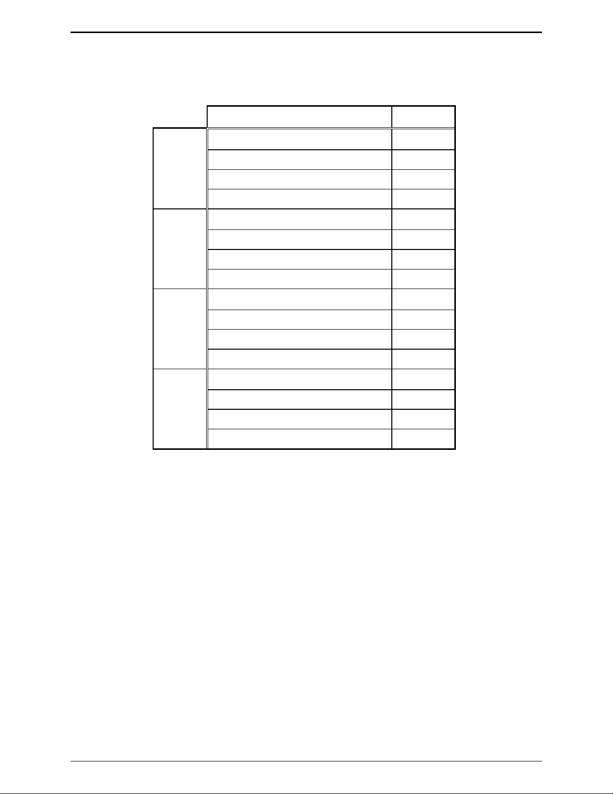
Installation IPE2500A and IPE2500A-MLS Paging Encoder/Desktop Controller
Line Connection for MLS
After completing the steps above, connect the lines. Use the table below to determine the line
connections on the Line Select board.
Description Pin
Line 1
Line 2
Line 3
Line 4
Two-wire RX/TX/four-wire TX tip J801-1
Four-wire RX tip J801-2
Two-wire RX/TX/four-wire TX ring J801-3
Four-wire RX ring J801-4
Two-wire RX/TX/four-wire TX tip J801-5
Four-wire RX tip J801-6
Two-wire RX/TX /four-wire TX ring J801-7
Four-wire RX ring J801-8
Two-wire RX/TX/four-wire TX tip J801-9
Four-wire RX tip J801-10
Two-wire RX/TX/four-wire TX ring J801-11
Four-wire RX ring J801-12
Two-wire RX/TX/four-wire TX tip J801-13
Four-wire RX tip J801-14
Two-wire RX/TX/four-wire TX ring J801-15
Four-wire RX ring J801-16
03/12 42

IPE2500A and IPE2500A-MLS Paging Encoder/Desktop Controller Installation
DTMF/H.E.A.R. Functions
As noted in the “Operation” section of this manual, the IPE2500A must be manually placed in “mute”
mode when used in a H.E.A.R. operation. This requires that one of the function keys to be programmed
for mute operation. While in CARD Suite under the IPE2500A programming archive, select the
Programmable Buttons tab. Select PB1–PB4 from either the Programmable Button Selection or the CTL
+ Programmable Button Selection (CTL + the programmable button means that the CTL button must be
depressed while pressing the assigned mute button). Select the Mute function from the drop-down box.
Be certain that the “mute duration” remains at “0” (on/off activation).
The parameters listed below are also programmable via CARD Suite Programming software. Refer to
the CARD Suite Help file for detailed programming instructions.
DTMF Decode Inter-digit Time - Allows the decoder to qualify the duration of a DTMF digit and to
further ensure that the DTMF sequence meets the desired customer specifications.
Minimum and Maximum Digit Count - Allows the decoder to ignore those DTMF sequences that are
not actual ID’s or ID’s of interest; the IPE2500A is capable of decoding one to eight digits.
DTMF Decode Alias - Provides alphanumeric display of the transmitting radio’s ID.
H.E.A.R. System Base ID - This ID is used to determine whether the incoming DTMF sequence is to
unmute the desk set speaker.
H.E.A.R. System Base ID Size - Allows proper comparison of an incoming DTMF sequence with the
programmed ID.
H.E.A.R. System Flags - Include audible alert on/off and duration of the audible alert.
H.E.A.R. System Alert Relay - When an incoming DTMF sequence matches the H.E.A.R. system base
ID, this optionally installed relay is asserted.
Audio Accessory/RS-232 Port
Use the eight-pin audio accessory/RS-232 port to connect a PC to the IPE2500A with the XAC0004A
Programming Cable in order to use the CARD Suite Programming software. See the CARD Suite
Software Help file for instructions on set up and programming options.
After programming is complete, connect an audio accessory, such as a desk microphone, gooseneck
microphone, boom microphone, headset, or footswitch, if desired. The microphone input type is passive,
with an input impedance of greater than 2k ohms and a nominal input level of −20 dBm.
Refer to the audio accessory/RS-232 port pinout on page 7 in the “Connectors” section of this manual.
43 03/12

Installation IPE2500A and IPE2500A-MLS Paging Encoder/Desktop Controller
Microphone Sensitivity Adjustments
After connections have been made, the IPE2500A must be configured for transmit and receive audio
levels. These adjustments are made using the front panel buttons. The microphone sensitivity
adjustment is used to compensate for different user voice levels and varied acoustical conditions. Refer
to the following instructions to adjust the different microphones.
Internal Microphone
1. Place the handset in the cradle.
2. While holding down
IC button, momentarily press VOLUME Up button ().
A single beep is heard to indicate that the microphone sensitivity level can be adjusted.
No audible beep indicates the microphone sensitivity adjustment function is already enabled.
3. Press and hold
Down to increase sensitivity or decrease microphone sensitivity. N
TRANSMIT, speak into the internal microphone, and press VOLUME Up or VOLUME
OTE: The display shows the
relative TX level as a number between 1 and 5. To confirm the absolute level, measure the transmit
level across the TX line pair using an ac millivolt meter or dBm meter.
4. After the adjustment has been made, press and hold the
VOLUME Down button. A single beep is heard to indicate the microphone adjustment has been
IC button, and momentarily press the
saved and the adjustment function had been closed. No audible beep indicates the microphone
adjustment function has already been closed.
Handset Microphone
1. With the handset off-hook, hold down the IC button and momentarily press the VOLUME Up button.
A single beep is heard in the earpiece to indicate that the microphone sensitivity level can be
adjusted. No audible beep indicates the microphone sensitivity adjustment is already enabled.
2. To adjust the sensitivity level, press the handset PTT button, speak into the handset microphone, and
press
VOLUME Up or VOLUME Down to increase or decrease the sensitivity level.
3. After adjustment has been made, hold down the
IC button and momentarily press the VOLUME Down
button. A single beep is heard to indicate the microphone setting has been saved, and the adjustment
function has been closed. No audible beep indicates the microphone adjustment has already been
closed.
Accessory Microphone
1. With the handset on-hook, hold down the IC button and momentarily press the VOLUME Up button.
A single beep is heard to indicate that the microphone sensitivity level can be adjusted. No audible
beep indicates the microphone sensitivity adjustment function is already enabled.
2. To adjust the sensitivity level, press the accessory microphone PTT/
accessory microphone, and press the
VOLUME Up or VOLUME Down to increase or decrease the
TRANSMIT button, speak into the
sensitivity level.
3. After the adjustment has been made, hold down the
IC button and momentarily press the VOLUME
Down button. A single beep is heard to indicate the microphone setting has been saved, and the
adjustment function has been closed. No audible beep indicates the microphone adjustment function
has already been closed.
03/12 44

IPE2500A and IPE2500A-MLS Paging Encoder/Desktop Controller Installation
Level Adjustments and Diagnostics
Main Diagnostics Selection
To enter the main programming mode:
1. Remove power from the desk set.
2. Reapply power and wait for the
“checking parameters - please wait.”) Press
PB1 through PB4 LEDS to illuminate. (The display will indicate
PB1, PB2, PB3, or PB4 to enter diagnostics.
3. The display will then indicate that the Main Diagnostics mode has been entered, and buttons PB1-
PB4 can now be pressed. PB1 through PB4 are used to select different parameter changes from the
default settings.
Programming Menu
The programming buttons, PB1 through PB4, are used to navigate the menu for specific installations and
to perform diagnostics. They are:
Line Output Level
Line In Sensitivity
Diagnostics
Tone Level Adjustments
45 03/12

Installation IPE2500A and IPE2500A-MLS Paging Encoder/Desktop Controller
The diagram below illustrates which buttons to press to access the programming menu features.
Press: To program:
PB1
PB2
PB3
Line Output Adjust Default: −10 dB
Line Input Sensitivity Default: −9 dB
Internal Diagnostics:
Press: To program:
PB1
Relay Module Diagnostics
or
Line Select Module Diagnostics
(depending on board installed)
PB2
PB4
Tone Level Adjust
DC Module Diagnostics
PB3
RS-232 Diagnostics
PB4
Keyboard Diagnostics
Press: To program:
PB2
PB3
CTL+PB1
Toggle Compressors
PB1
Sidetone Level Adjust Default: 0 dBm
Alert Tone Level Adjust Default: 0 dBm
Page Level Adjust Default: 0 dBm
Press: To program:
PB1
PB2
Toggle Microphone Compressor On/Off
Toggle Receive Compressor On/Off
03/12 46

IPE2500A and IPE2500A-MLS Paging Encoder/Desktop Controller Installation
Reloading Factory Defaults
Desk sets are shipped from the factory with default settings that meet most installation requirements.
However, it is important to verify that these parameters are adjusted to meet your specific installation
needs.
To reload factory defaults, enter the Main Diagnostic Selection as described above. After entering this
mode, press
CTL + VOLUME Up. The unit will automatically reset and show that the parameters are
corrupt. Follow the instructions on the display. For some models, this may happen twice.
N
OTE: If your unit has been programmed with CARD Suite software, reloading the factory defaults will
reset all parameters that have been programmed.
PB1 – Line Output Adjust
An ac voltmeter or SinAdder meter should be connected across the line to achieve the proper level
setting. Ensure that the line is terminated with a 600-ohm load.
After entering the Main Diagnostic selection mode, press the
PB1 button. The display will indicate the
current setting, which is set at the factory at −10 dBm. The range for this setting is variable from off to
+12 dBm. See the Line Output Adjustment table for approximate settings. The desk set buttons are used
as follows in the Line Output Adjust mode:
Button Line Output Level Adjust ment Mode Function:
VOLUME Up Increases the output level, verifying the proper level with the meter
connected to the line.
CTL + VOLUME Up Increases the output level by 10.
VOLUME Down Decreases the output level, verifying the proper level with the meter
connected to the line.
CTL + VOLUME Down Decreases the output level by 10.
TRANSMIT
MONITOR
IC
Saves the current setting and exits back to the main selection mode.
Restores the previously programmed setting.
Exits the line output adjustment mode without saving the selection, but
maintains the current setting until the power to the unit is cycled. This is
useful for experimenting with different settings.
Using a communications service monitor/analyzer and a tone generator/SinAdder, connect the analyzer to
the radio base station antenna port. Inject a 1000 Hz tone into the input of the tone remote adapter
(simulating console). Manually key the radio and adjust the level of audio signal to set the audio
deviation of the radio to the desired level. Note the level of the tone, and using the Line Output
Adjustment Table below, program the desk set to the closest level.
47 03/12

Installation IPE2500A and IPE2500A-MLS Paging Encoder/Desktop Controller
Program the desk set’s line level to the setting that approximates the audio level previously measured.
Refer to the following table for these settings:
Line Output Adjustment Table
Setting Line Level (600-ohm)
03 −10 dBm
07 −5 dBm
0C 0 dBm
18 +5 dBm
2D +10 dBm
If an RF service monitor is not available, use a portable or mobile radio. Transmit to the station and
measure the nominal voice audio on the desk set telephone line. Set the desk set receive level to the
nearest level that was measured according to the table above.
Line Out Adjust for the IPE2500-MLS
The IPE2500A-MLS allows the adjustment of each of the four available lines. When setting line output
levels for an MLS desk set, follow the same procedure described above but select the appropriate line to
adjust using the programmable buttons: PB1 for line 1, PB2 for line 2, PB3 for line 3 and PB4 for line 4.
Multi-Select Considerations for the IPE2500-MLS
The architecture of the MLS board allows for simultaneous transmission on any of the four available
lines. However, due to the design of the circuit, special considerations regarding line levels and line
termination must be addressed. When a multi-select combination is engaged during transmission, the
actual wire lines are physically connected together. If a line in the multi-selection has line termination
enabled, it is presented as a load to the other lines in the selection during transmission resulting in a
heavier load for the output driver. To provide compensation for this, the line output adjustment includes
an additional setting that instructs the unit to add additional output gain during multi-select transmissions
when lines in the selection have line termination enabled.
By default, line-termination compensation is enabled for all lines of the MLS board. If a parallel unit on
a particular line provides the line termination but does not present a significant transmit load to the desk
set, this compensation can be disabled using the
CTL + PB1, 2, 3 or 4 combination. When line
termination compensation is enabled, a ‘T’ will be seen to the right of the line out gain during the line out
adjustment.
In addition to line termination compensation during multi-select transmission, the unit must select one
line out gain during a multi-select transmission. In some installations, the line out gain of each line may
not be the same. This allows for proper line level for single channel transmission. However, during a
multi-select transmission, only one gain can be used. The gain used will be the highest gain of any
selected line. Careful consideration during system installation should be observed to try to equalize the
levels if multi-select transmissions are to be used often. High output level settings may result in
distortion of the transmit audio particularly when three to four lines are selected.
03/12 48

IPE2500A and IPE2500A-MLS Paging Encoder/Desktop Controller Installation
PB2 - Line-In Sensitivity
After entering the main programming selection mode, press the PB2 button to allow adjustment of the
line-in sensitivity. This adjustment allows the desk set to compensate for a range of 0 to 15 dB of line
loss in 3-dB increments. The compensation is considered a pre-gain to the line-in circuitry of the desk
set.
For example, if the RX audio output of the radio tone panel or ITA2000 is 0 dBm, and the telephone
system has 10 dB of line loss, the desk set line input sensitivity should be set to level 4 (−9 dBm) to
accommodate the 10 dB of incurred line loss.
After pressing the
Button Line-i n Sensitivity Mode Function:
VOLUME Up Decreases the line-in sensitivity or reduces the pre-gain for the line input.
VOLUME Down Increases the line-in sensitivity or increases the pre-gain for the line input line.
TRANSMIT
MONITOR
IC
PB2, the display indicates the current line-in setting. The buttons function as follows:
Saves the current setting and exits back to the main selection mode.
Restores the previously programmed setting.
Exits the line-in sensitivity mode without saving the selection, but maintains the
current setting until the power to the unit is cycled. This is useful for experimenting
with different settings.
49 03/12

Installation IPE2500A and IPE2500A-MLS Paging Encoder/Desktop Controller
PB3 – Internal Diagnostics
Four internal diagnostic modes are available: (PB1) relay or MLS module diagnostics depending on the
board installed, (PB2) DC module diagnostics, (PB3) RS-232, and (PB4) keyboard. After entering the
Internal Diagnostics mode, they are accessed using the programming buttons as follows:
PB1 – Relay or MLS Module Diagnostics (depending on board installed)
Relay Module: This function is accessible via Main Diagnostics, then Internal Diagnostics (
PB3). The
XRC0001A Relay Option Kit must be installed in the unit under test. This function allows the relay I/O
module to be exercised. The display indicates the status of:
Inputs – IN
Relay – OUT
By pressing any key (except
TRANSMIT) starting at relay 1 and progressing up to relay 4, the relays close
and then open. The numeral 1 in the OUT position indicates the relay should be closed. LEDs on the
relay I/O module also indicate the status of each relay.
To exercise the inputs, each input can be grounded. This is indicated by a numeral 1 in the IN position
associated with the input. As each input is shorted to ground, the corresponding 1 in the IN position
indicates a 0.
TRANSMIT to exit the relay module diagnostics.
Press
MLS Module: If the MLS module is installed (included in the IPE2500A-MLS or XML001A Kit) the
Line Select board diagnostic replaces the relay module diagnostics shown above. This diagnostic allows
the line select module to be exercised.
Button(s) Line Select Module D iagnostics Function:
Any button except
TRANSMIT.
By pressing any key, except TRANSMIT, starting at line 1 and progressing up to
line 4, each line is selected and the previous unselected. The display and
corresponding
PB1 through PB4 LEDs indicate which line is currently selected.
Press TRANSMIT to exit the MLS module diagnostics.
03/12 50

IPE2500A and IPE2500A-MLS Paging Encoder/Desktop Controller Installation
PB2 – DC Module Diagnostics
This function is selected after entering Internal Diagnostics (
PB3).
DC Module: If the dc module (XDC0001A Kit) is installed, this mode allows the board to be exercised
with both positive and negative currents and sets the DCLOTL. The threshold for DCLOTL is
adjustable, but is factory preset for most installations. The asterisk (*) is present in the lower right corner
if the line voltage is above the preset DCLOTL threshold.
Button(s) DC Module Diagnosti cs Mode Function:
VOLUME Up or
VOLUME Down
Increases/decreases the dc value sent to the dc module. This value
determines the dc current level and is a hexadecimal number ranging from 00
(lowest current) to 0x3F (highest current).
CTL + VOLUME Up or
CTL + VOLUME
Works in the same manner as the function above, but increases or decreases
the value by 10 rather than 1.
Down
TRANSMIT
MONITOR
Exits the dc module diagnostic mode.
Toggles to the polarity of the current being generated. The display shows
+ for positive and − for negative polarity.
CTL + PB1
Allows the DCLOTL threshold to be set. In order for this setting to be done
properly, a dc supply must be connected to the line pair with 3 volts. When
CTL + PB1 to pressed, the unit reads the dc voltage on the line and saves the
value for future DCLOTL operation.
CTL + PB4
Like CTL + PB1, this key sequence sets the DCLOTL threshold. However,
no dc supply is needed. To set the threshold, set the current out into the
proper line load (typically 8 kilohms) by using the
buttons. When the proper current is reached, press
VOLUME Up or Down
CTL + PB4. The unit
reads the voltage for future DCLOTL operation.
51 03/12

Installation IPE2500A and IPE2500A-MLS Paging Encoder/Desktop Controller
PB3 – RS-232 Diagnostic
This function is accessible via Main Diagnostics, then Internal Diagnostics (
PB3), and exercises the RS-
232 port TX and RX data. To run this test, disconnect anything connected to the programming connector
on the back of the unit, and short pins 2 and 7 of the connector.
Once the short is completed, this unit sends data on the TX wire for receipt on the RX wire. If the same
data is received on the RX wire, the unit continues to send data. If no data, or incorrect data is received,
the unit stops sending data and displays failure.
Note that this diagnostic does not guarantee standard RS-232 levels. If the diagnostic functions, but the
unit does not operate with a PC or printer, verify with an oscilloscope that the proper RS-232 levels are
present.
Press the
TRANSMIT button to exit the RS-232 diagnostics.
PB4 – Keyboard Diagnostic
This function is accessible via Main Diagnostics, then Internal Diagnostic (
PB3) and verifies that the
keyboard is operating correctly. After entering the keyboard diagnostic mode, the display shows:
KEYBOARD TEST
KEYCODE:
When any key is pressed (except
XX
TRANSMIT), the corresponding keycode is displayed. Refer to the
keycode table that follows:
Button Keycode (Hex) Button Keycode (Hex)
0–9
*
#
TRANSMIT
00–09
0e
0f
No code
PB1 – PB4
ALERT
PAGE
CLEAR
30–33
45
44
47
(Will exit test.)
MONITOR
IC
VOLUME Down 20
VOLUME Up 21
11
13
SELECT
DOWN
UP
46
40
41
Press
TRANSMIT to exit the keyboard diagnostics.
03/12 52

IPE2500A and IPE2500A-MLS Paging Encoder/Desktop Controller Installation
PB4 – Tone Level Adjust
This function is accessible via Main Diagnostics mode select (PB4), and allows adjustment of the levels
of sidetone (
then select
PB1), the alert tones (PB2), and the page tones (PB3). The tone level adjust will display,
PB1, PB2, or PB3.
The sidetone level used for speaker tones can be adjusted to suit the user.
The alert and page tone line levels can be adjusted relative to HLGT.
PB1 – Sidetone Level Adjust Mode
This mode allows the adjustment of the sidetone level to −15 dB in 3-dB steps:
Button(s) Sidetone Level Adjust Mode Function:
VOLUME Up or
VOLUME Down
Increases/decreases the sidetone line level. Each time the VOLUME Up or
VOLUME Down button is pressed, a beep is generated and the LCD display shows
the new setting.
TRANSMIT
Exits the sidetone level adjust mode and returns the unit to the tone level
adjustment screen.
PB2 – Alert Tone Level Adjust Mode
This mode allows the alert tone line level to be adjusted to −15 dB relative to the HLGT in 3-dB steps:
Button(s) Alert Tone Level Adjust Mode Function:
VOLUME Up or
VOLUME Down
Increases/decreases the alert tone line level. Each time the VOLUME Up or
VOLUME Down button is pressed, a beep is generated and the LCD display shows
the new setting.
TRANSMIT
Exits the alert tone level adjust mode and returns the unit to the tone level
adjustment screen.
PB3 – Page Tone Line Level Adjust Mode
This mode allows the page tone line level to be adjusted to −15 dB relative to the HLGT in 3-dB steps:
Button(s) Page Tone Line Level Adjust Mode Functi on:
VOLUME Up or
VOLUME Down
Increases/decreases the alert tone line level. Each time the VOLUME Up or
VOLUME Down button is pressed, a beep is generated and the LCD display shows
the new setting.
TRANSMIT
Exits the page tone line level adjust mode and returns the unit to the tone level
adjustment screen.
53 03/12

Installation IPE2500A and IPE2500A-MLS Paging Encoder/Desktop Controller
CTL-PB1– Toggle Compressors
This function is accessible via Main Diagnostics mode select (CTL-PB1), and allows the microphone
(
PB1) and audio receive compressor (PB2) to be enabled or disabled. The factory default is that both
compressors are enabled.
It may be desirable, depending on background noise, that the compressor contributes to the noise floor of
the microphone and/or receive audio. To reduce this possibility, the compressor for each can be
disabled. However, care must be observed in the setting of the receive and microphone sensitivities since
clipping of high-level audio signals is possible with the compressor disabled.
PB1 – Toggle Microphone Compressor On/Off
This mode allows the microphone compressor to be enabled or disabled:
Button(s) Toggle Microphone Compressor On/Off
PB1
TRANSMIT
Toggles the microphone compressor on and off.
Exits the toggle microphone compressor mode and returns the unit to the toggle
compressor screen.
PB2 – Toggle Audio Receive Compressor On/Off
This mode allows the audio receive compressor to be enabled or disabled:
Button(s) Toggle Audio Receive Compressor On/Off
PB2
TRANSMIT
Toggles the audio receive compressor on and off.
Exits the toggle audio receive compressor mode and returns the unit to the toggle
compressor screen.
03/12 54

Theory of Operation
General Desk Set Overview
The IPE2500A is a multi-processor design employing state-of-the-art DSP technology to achieve superior
performance over typical analog and single-processor designs. This allows for ultimate flexibility in
audio processing.
The heart of the design consists of U1, the DSP; and U3, the microcontroller. The DSP is responsible for
audio processing of receive and transmit audio. This includes notch and line filtering, tone detection,
tone generation, audio level compression and setting, and audio routing.
The microcontroller is responsible for controlling the functions of the DSP, programming, the LCD
display, keyboard scanning, support of the relay, dc, and multi-line select modules and general I/O and
general operational functions.
Receive Audio
Receive audio is presented to the desk set through the line transformer providing for the necessary load.
The audio is buffered and switched by U14. U14 controls the source of the receive audio: line1 for twowire, or line 2 for four-wire operation.
The appropriate receive audio is then passed to the gain stage, consisting of U21 and U12. U12 provides
the compression mechanism used by the DSP to keep the receive audio below the maximum level of
approximately –6 dBm. This compressor can be disabled using the desk set diagnostics. After the
receive audio has been properly compressed, it is passed to A/D section of U15 where it is converted to
digital for use by the DSP and also to P400-12 for data conditioning.
The input impedance for two-wire operation is controlled by U10. When U10-1 is asserted, the input
impedance is 560 ohms. When U10-1 is unasserted, the input impedance is bridging.
Speaker Audio
Speaker audio is originated from the DSP in digital format. The DSP combines the receive audio, which
is notched for tone control operation, side-tone, and beep tones to generate the speaker audio.
The speaker audio is converted to analog using the D/A section of U17. It is then passed through the
volume control stage consisting of U13 and U22 before being passed to the handset earpiece and the
speaker amplifier, U18.
The microcontroller or the DSP can mute the speaker amplifier. The microcontroller mutes the speaker
audio using U5-C8, in cases such as parallel mute or the user muting via a key press. The DSP uses a
speaker squelch algorithm to squelch the speaker when no audio is being output to the speaker. This
squelch will remain open for two seconds after no audio is present. The DSP then mutes the speaker
using U1-88.
55 03/12

Theory of Operation IPE2500A and IPE2500A-MLS Paging Encoder/Desktop Controller
Transmit Audio
Transmit audio is originated from the DSP in digital format. The DSP combines control tones, paging
tones and voice audio to generate the transmit audio.
It is converted to analog by the D/A section of U15. Upon conversion to analog, the audio is passed
through the line-out gain stage consisting of U11 and U10 for level adjustment. U10 also provides the
proper line drive and line enable for the transmit audio.
The proper level audio is then routed to the line 1 transformer for output from the desk set. In addition to
the transmit audio, data is combined with the transmit audio prior to line-out compensation at U11-3.
U10-1 is the line-driver enable for the transmit audio. This provides for a 560-ohm transmit output
impedance.
Microphone Audio
The three sources for mic audio are the internal, handset, and audio accessory mic. The microcontroller
controls which mic is used based on the source of the PTT. The selected mic audio is gated between the
handset/internal and the audio accessory mic by U14 using the outputs of U5–C6. The selection of the
handset and internal mic is controlled by U5–C5.
When U5-C5 is high, U25 will provide a high level of VMB or mic-bias voltage to the internal mic, thus,
enabling the internal mic and disabling the handset mic. If U5–C5 is low, the internal mic will not have
mic bias, but the handset mic will and, thus, the handset mic is selected.
The audio accessory port can be configured to provide a mic bias to the audio accessory. This is
controlled by the microcontroller using U5–C7. Each mic audio is gain compensated by U22 so that the
same level is presented to the mic gain-stage consisting U12 and U22.
The audio is then presented to the A/D section of U17 where it is converted to digital for use by the DSP.
The DSP compresses the mic audio using U13 and, if tone control is in use, notches the mic audio prior
to combining it with the transmit audio. This compressor can be disabled using the desk set diagnostics.
Guard Tone Detection
When configured for tone control operation, the IPE2500A must detect guard-tone from parallel units to
restrict transmissions. This is done by first auto-leveling the transmit audio input from line 1 using U12.
The audio is then converted to digital using the A/D section of U16. The DSP this processes this audio
to determine if guard tone is present.
03/12 56

IPE2500A and IPE2500A-MLS Paging Encoder/Desktop Controller Theory of Operation
DC Control Module (not compatible with MLS operation)
The reference designators listed in this section refer to the dc control schematics unless otherwise stated.
The dc control module provides a method of generating dc control currents on line 1 and detecting line
voltages to restrict transmission during a parallel transmit. The microcontroller provides the dc control
current information to the dc control module in a serial format to U505.
Using the resistor ladder consisting of LR1A–LR6B, this information is converted into a dc voltage.
This dc voltage then provides a control reference, using U503 and Q507, to the comparator circuit
consisting of U502 and U501.
U501 then causes Q500 and T500 to generate the necessary switch voltage to achieve the desired line
current. This line current is then converted to a voltage reference using U502 and R532 that is fed back
and compared again to the reference voltage provided by Q507.
The direction of the current, positive or negative, is controlled by U505-7. This signal causes either
U510 or U511 to be switched on. If U510 is switched on, then U511 is switched off and the current is
output on J13-8 and returned on J13-7.
If U511 is switched on then U510 is switched off and the current is output on J13-7 and returned on J13-
8. Before any current can be output and returned, U505-7 must be high. This, in turn, provides a ground
to Q512 and Q513 that allows U510 or U511 to be switched on.
Relay Control Module (not compatible with MLS operation)
The reference designators listed in this section refer to the relay control schematics unless otherwise
stated.
The relay control module is used to provide closures out via relays and sense closures via closures to
ground. The microcontroller provides closure-out information and reads closure-in information via serial
data. Closure outputs are controlled by the data in U701. Closure senses inputs are read from U702.
To provide a closure on relay 1, the microcontroller asserts U701-15. This, in turn, drives the
corresponding Q701 that provides the ground for the coil of K701. To provide a closure sense input on
input 1, J701-5 must be grounded.
This, in turn, is latched into U702 by the microcontroller where the microcontroller takes the appropriate
action.
57 03/12

Theory of Operation IPE2500A and IPE2500A-MLS Paging Encoder/Desktop Controller
Multi-Line Select Module
The reference designators listed in this section refer to the multi-line select schematics unless otherwise
stated.
The transmit and receive audio paths to and from the desk set are routed to the NSL PCBA through P802.
Control lines for four individual radio stations are brought into the desk set onto terminal strip J801.
Each line is selected individually through K800–K803. The relays are driven from the microcontroller
on the desk set via the SPI bus register/latch V801. The SPI bus interfaces on P800-8, 10, 11, 12, and 13.
Each channel has an adjustable line activity detector that is also interfaced to the desk set microcontroller
via the SPI bus at V809.
Receive audio balance for all four lines is adjusted with pot 1 to pot 4 and the resultant audio is switched
to either selected (select) or background (unselect) status through audio gates V804 and V805. The
unselect and select audio is mixed and sent to the desk set PCBA through driver V808 and T806.
Reset Circuit
Both the DSP and the microcontroller use the EPROM, U2. When coming out of reset, the DSP must
boot its software from the EPROM. In doing so, it asserts U1-21, BMS, low, causing the microcontroller
to remain reset.
After the DSP has completed loading its software from the EPROM, it no longer requires access to the
EPROM. The DSP then disasserts BMS, allowing the microcontroller to come out of reset. The
microcontroller then executes its software from the EPROM.
03/12 58

CARD Suite Programming Software
General Description
GAI-Tronics’ CARD Suite Programming Software, included in the No. XAC4000A Programming
Bundle CD, is needed to program some of the functions and parameter settings of the dispatch
equipment. It allows entry of operational programming data into your personal computer for transfer to
the equipment. The programmed data can be retrieved, edited, archived, and printed in hard copy for
record keeping. Detailed programming information can be found in CARD Suite’s Help file. The
following information is provides as guidance to initiate the programming application.
Connection
The GAI-Tronics equipment must be connected to your personal computer with the programming cable,
part number XAC0004A, before the programming software can be used. To make this connection, attach
the cable to the COM1 or COM2 connector on the computer. Connect the other end to the programming
jack on the GAI-Tronics equipment.
Installation
The minimum system requirement necessary to support the CARD Suite Software Application is
Windows 95 or newer. However, CARD Suite is not compatible with Windows NT. It is compatible
with Windows XP (Home or Professional), Vista, and Windows 7 when used in Virtual Mode.
The CARD Suite Programming Application components are contained on CD-ROM. Please exit all
other programs that are running until the installation is complete.
1. Place the CD in the PC’s CD-ROM drive. If the “auto-run” feature on your CD-ROM drive is
enabled, a program selection chart will be displayed. Select Card Suite for downloading. If for any
reason the installation does not start up automatically, it can be run from the Start menu.
Select the
x:\Setup.exe where x represents the drive letter that is associated with your CD-ROM drive. A
CARD Suite icon should appear on the desktop display after successful installation.
2. After opening the program, select the appropriate product icon, click on File in the toolbar and select
New Archive to begin creating an archive.
3. Enter an archive description (name) and customer/site (name), select the method of creating the
archive (default values or reading a connected unit), and click Ok button to create the archive.
4. View the Help file for programming guidance.
START button and then select Run from the Start menu. At the prompt, type
Reading the Unit
1. After opening the program, select the appropriate product icon, click on File in the toolbar and select
New Archive to begin creating an archive.
2. Enter an archive description (name) and customer/site (name), select the method of creating the
archive (default values or reading a connected unit), and click Ok button to create the archive.
3. View the Help file for programming guidance.
59 03/12

CARD Suite Programming IPE2500A & IPE2500A-MLS Paging Encoder/Desktop Controller
CARD Suite Programming
To program a unit that has no saved archive, follow the steps for Reading the Unit on the previous page.
To open an existing archive for editing, first click on the appropriate product icon, then double click on
the archive you wish to edit from the list of saved archives. This will open the archive for that particular
unit.
After all changes are made, you must save and close the archive prior to programming the unit with
changes by clicking the OK button at the bottom of the screen.
After saving and closing the archive you can program the unit by selecting the archive from the list of
saved archives, then selecting Program Unit under the Tools dropdown.
Editing Screen
The status bar on the bottom of the window gives instructions on setting the desired parameter. Editing
some parameters depends on the state of another parameter, such as in the Programmable Buttons screen.
After changing a parameter, appropriate changes are automatically made to any other parameter on the
screen that depends on it.
03/12 60

T roubleshooting
Troubleshooting the IPE2500A Desk Set
The following is a list of potential problems you may encounter and possible solutions.
Problem Possible Solution
The unit has no LED or
LCD display
Check for a blown fuse.
The keyboard does not
respond.
Ensure that the polarity of the PTT and Monitor outputs of the accessory
There is continuous noise
in the receive audio.
No, low, or distorted
transmit audio.
Ensure that the line output level is properly adjusted.
Ensure that the microphone compressor is enabled.
Ensure that the radio/adapter is properly adjusted for the audio being
The desk set will not cause
the transmitter to key.
Ensure that the line out level is properly adjusted.
Ensure that the unit is receiving dc power.
Ensure that the PTT or monitor input on the audio accessory port is not
activated.
match the CARD Suite programmed polarity for the audio accessory port.
If the receive audio is derived from a detector or discriminator, continuous
noise is heard unless the receiving unit has an internal squelch circuit.
Ensure that the microphone sensitivity is properly adjusted for the
microphone in use.
transmitted.
Ensure that the proper guard tone and function tones/dc-current parameters
have been programmed with the CARD Suite software.
Ensure that the remote adapter is configured and connected to the radio
properly.
Ensure that there is a valid circuit line from the desk set to the remote
adapter, meeting specified line-loss criteria.
Ensure that the private circuit is balanced by making sure neither side of
the telephone line is grounded.
RX Audio is low or
distorted.
Ensure that the line-input sensitivity is properly adjusted.
Ensure that the audio receive compressor is enabled.
Ensure that the remote adapter is wired correctly, including the RX audio
61 03/12
Ensure that the audio level is properly adjusted for the particular speaker.
pair. Audio quality is limited by the quality of the private radio circuit or
leased lines between the radio equipment and the desk set. In some cases,
equalization of the lines or line conditioning may be required to ensure a
reasonably flat audio response on the line.
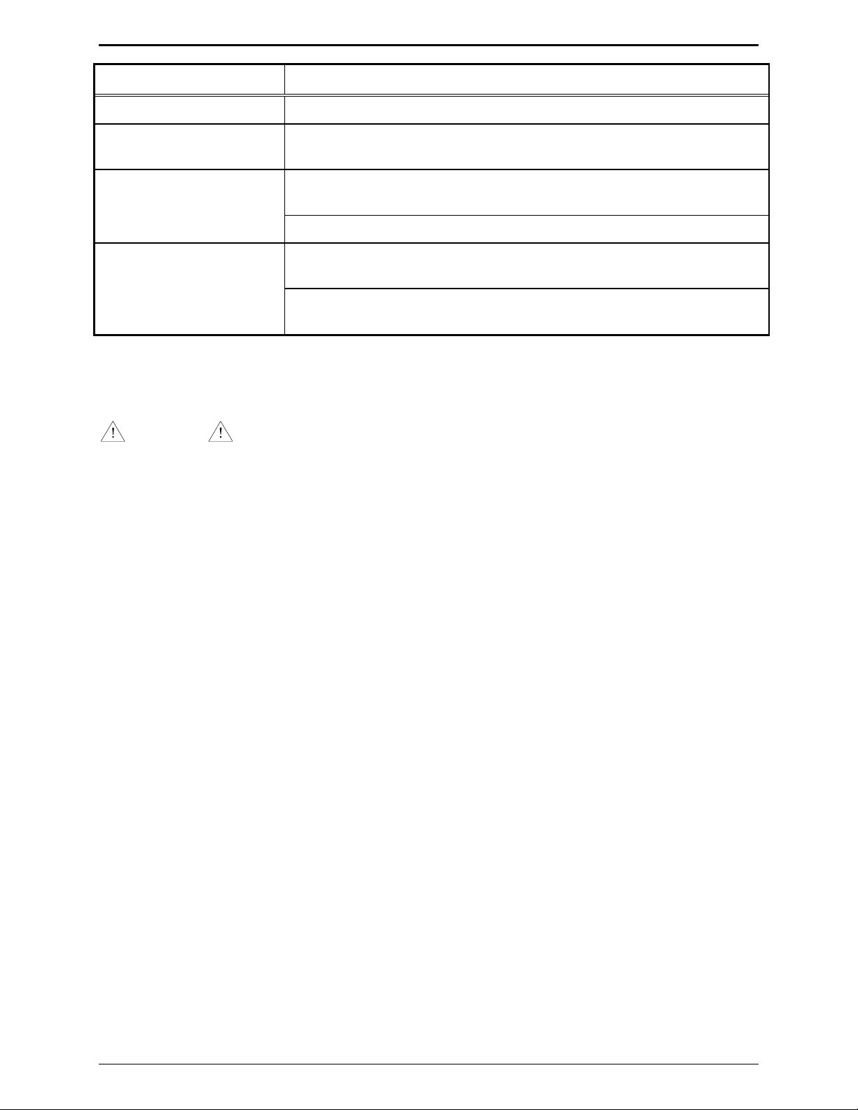
Troubleshooting IPE2500A and IPE2500A-MLS Paging Encoder/Desktop Controller
Problem Possible Solution
No or low transmit audio Ensure that the leased line being used does not have excessive line losses.
LOTL never/always on. Ensure that the DCLOTL threshold has been properly set using the internal
diagnostics.
No line current Ensure that the dc module can output current by using the internal
diagnostic.
Ensure that the line between the desk set and dc adapter has dc continuity
Not able to change the
selected frequency.
If direct DTMF is enabled, ensure that the SELECT button is first pressed
to enter the frequency selection mode.
If direct DTMF is enabled and this is an IPE2500A-MLS, frequency
selection is not possible except through the use of programmable buttons.
Fuse Replacement
CAUTION
For continued safe operation, replace fuses with the same type.
Fuses F1 and F2 are Bussmann C515S 1.25A SB 2AG.
Fuse F401 is Bussmann GMA 1A 5X20MM.
03/12 62

Circuit Boards
63 03/12

Circuit Boards IPE2500A and IPE2500A-MLS Paging Encoder/Desktop Controller
64

IPE2500A and IPE2500A-MLS Paging Encoder/Desktop Controller Circuit Boards
65

Circuit Boards IPE2500A and IPE2500A-MLS Paging Encoder/Desktop Controller
Multi-Line Select Board
(IPE2500A-MLS)
66

Schematics
67 03/12
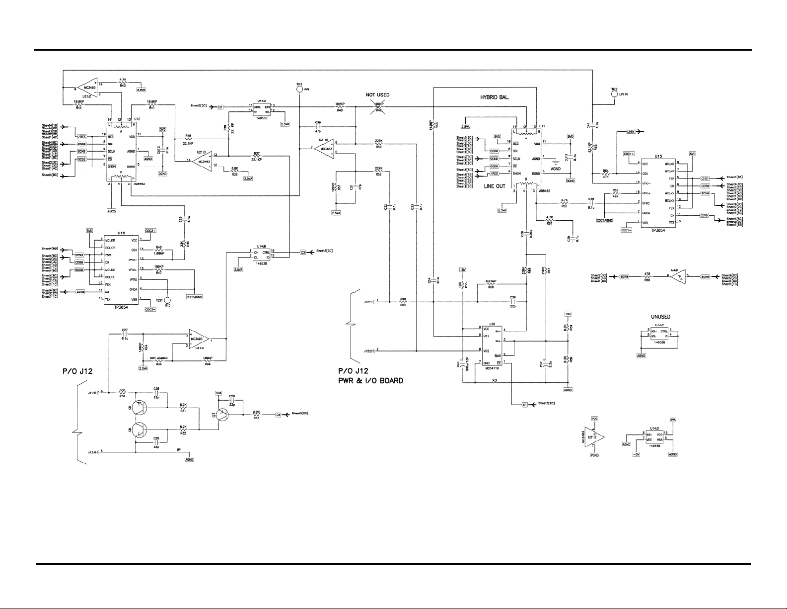
Schematics IPE2500A and IPE2500A-MLS Paging Encoder/Desktop Controller
Tone RC Desk Set - Line Interface - Sheet 1
68

IPE2500A and IPE2500A-MLS Paging Encoder/Desktop Controller Schematics
Tone RC Desk Set - User Audio I/O - Sheet 2
69

Schematics IPE2500A and IPE2500A-MLS Paging Encoder/Desktop Controller
Tone RC Desk Set - Control Microprocessor I/O - Sheet 3
70
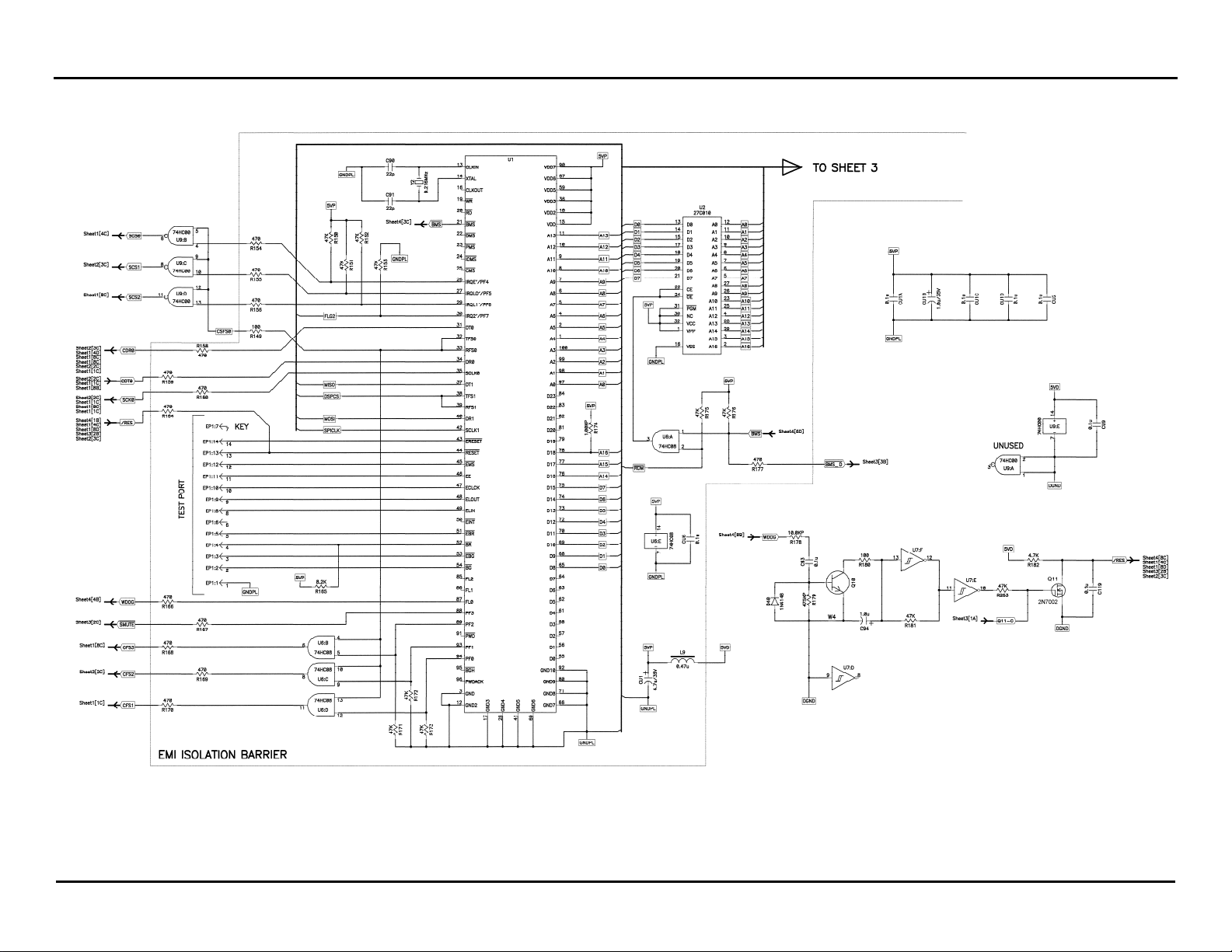
IPE2500A and IPE2500A-MLS Paging Encoder/Desktop Controller Schematics
Tone RC Desk Set - DSP Block - Sheet 4
71
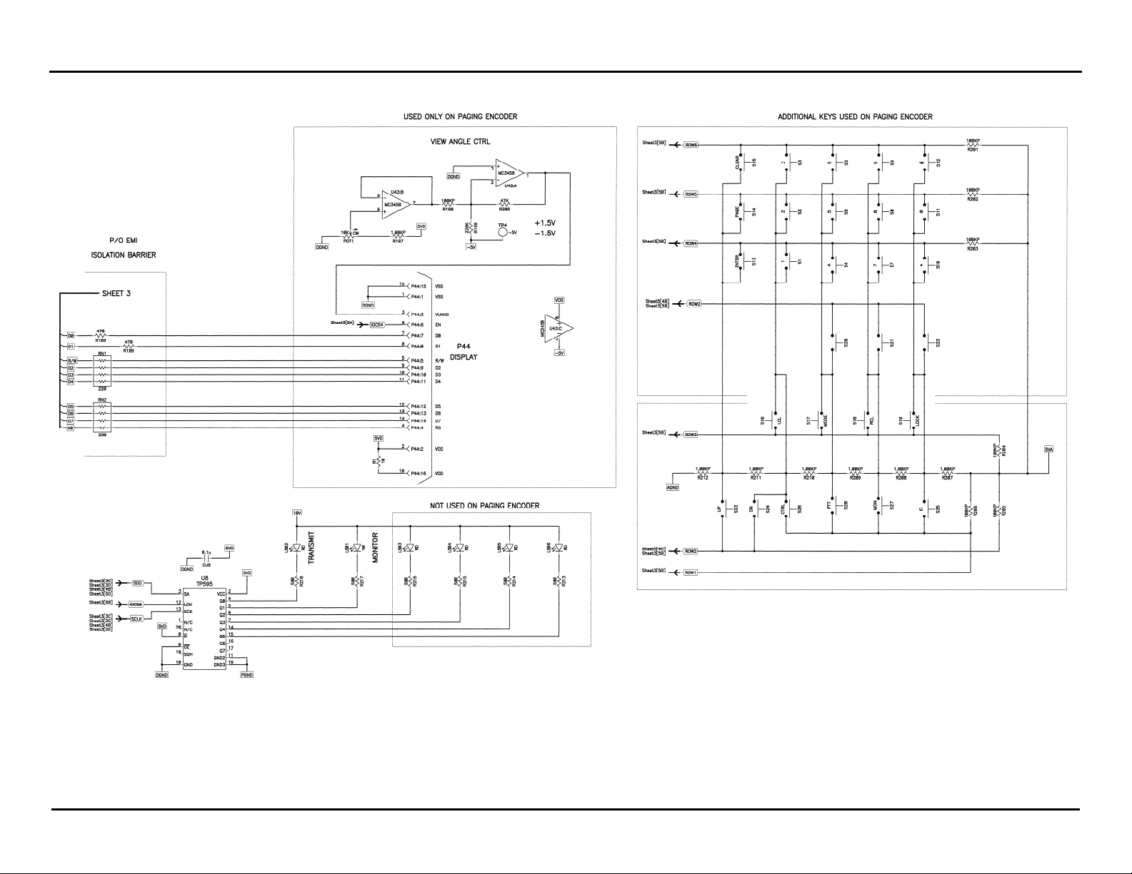
Schematics IPE2500A and IPE2500A-MLS Paging Encoder/Desktop Controller
Tone RC Desk Set - Tone Key Panel - Sheet 5
72
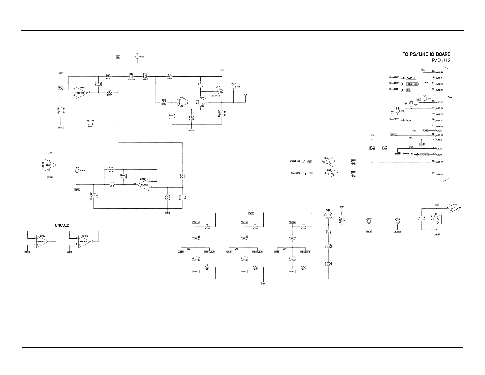
IPE2500A and IPE2500A-MLS Paging Encoder/Desktop Controller Schematics
Tone RC Desk Set Power Supply - Sheet 6
73

Schematics IPE2500A and IPE2500A-MLS Paging Encoder/Desktop Controller
Schematic - Sheet 7
74

IPE2500A and IPE2500A-MLS Paging Encoder/Desktop Controller Schematics
Schematic – Sheet 8 DPS PCBA
75

Schematics IPE2500A and IPE2500A-MLS Paging Encoder/Desktop Controller
Multi-Line Select Sheet 1 of 4 (5/02)
76

IPE2500A and IPE2500A-MLS Paging Encoder/Desktop Controller Schematics
Multi-Line Select Sheet 2 of 4
77

Schematics IPE2500A and IPE2500A-MLS Paging Encoder/Desktop Controller
Multi-Line Select - Sheet 3 of 4
78

IPE2500A and IPE2500A-MLS Paging Encoder/Desktop Controller Schematics
Multi-Line Select Sheet 4 of 4
79

Schematics IPE2500A and IPE2500A-MLS Paging Encoder/Desktop Controller
80

Term Definition
Definitions and Acronyms
CSQ
CTCSS
CDCSS
HLGT
LLGT
PTT
OTES:
N
Carrier squelch
A means of grouping users of a common radio channel. Subaudible tones are transmitted
with audio; a particular radio’s speaker (or the speakers of a group of radios) will unmute
to broadcast a transmission only if the associated subaudible tone identifies it as
belonging to the radio’s user group.
A system analogous to CTCSS but using low speed digital signaling instead of subaudible
tones.
High level guard tone
Low level guard tone
Push-to-talk
81 03/12
 Loading...