


Pub. 42004-392G
G A I - T R O N I C S ® C O R P O R A T I O N
A H U B B E L L C O M P A N Y
Model LE200-RM
Rack-Mount Page/Party® Line Extender
T A B L E O F C O N T E N T S
Confidentiality Notice ..................................................................................................................... |
1 |
General Information....................................................................................................................... |
1 |
Line Extender and Sub-Component Details......................................................................................... |
2 |
PCBA Access........................................................................................................................................................ |
3 |
Audio Termination Connection Module – Optional Model 12118-011 Kit.......................................................... |
4 |
Input/Output (I//O) Termination Connection Module – Optional Model 12118-012 Kit..................................... |
5 |
Main PCBA........................................................................................................................................................... |
6 |
Features and Functions.................................................................................................................. |
7 |
Page Line Audio Transmission.............................................................................................................. |
7 |
Page Line Audio Monitoring Output .................................................................................................... |
8 |
Page Line Audio Detect Output Contact .............................................................................................. |
9 |
Page Line FSK Data Transmission (SmartSeries Systems) ................................................................ |
9 |
Page Line 50 kHz VLC Transmission................................................................................................. |
10 |
Page Line Ground Fault Detection...................................................................................................... |
10 |
Page Line Ground Fault Re-generation.............................................................................................. |
11 |
Page Line Ground Fault Output Contact........................................................................................... |
11 |
Party Line Audio Transmission........................................................................................................... |
12 |
Party Line Off-Hook Regeneration..................................................................................................... |
12 |
Party Line Off-Hook Detection............................................................................................................ |
13 |
Audio Line Connection Relays ............................................................................................................ |
14 |
Audio Line Muting................................................................................................................................ |
15 |
Page/Party® Line Balance..................................................................................................................... |
16 |
Contact Closure Inputs & Relay Outputs (I/0) .................................................................................. |
17 |
Echo Cancellation ................................................................................................................................. |
17 |
Manual Initiation of Echo Canceling .................................................................................................................. |
17 |
Data Links between Line Extenders............................................................................................. |
18 |
T1/E1 Data Link.................................................................................................................................... |
18 |
Low Voltage Differential Signaling (LVDS) Data Link..................................................................... |
18 |
Configuring the Data Links ................................................................................................................. |
19 |
GAI-Tronics Corporation 400 E. Wyomissing Ave. Mohnton, PA 19540 USA
610-777-1374 800-492-1212 Fax: 610-796-5954
VISIT WWW.GAI-TRONICS.COM FOR PRODUCT LITERATURE AND MANUALS

Table of Contents |
Pub. 42004-392G |
MODEL LE200-RM RACK-MOUNT PAGE/PARTY® LINE EXTENDER |
|
T1/E1 Data Format Selection.............................................................................................................................. |
19 |
T1 Line Build-out Settings.................................................................................................................................. |
19 |
T1/E1 Receiver Equalization Gain Limit............................................................................................................ |
20 |
T1/E1 Clock Source............................................................................................................................................ |
20 |
T1/E1 Data Line Grounding ............................................................................................................................... |
21 |
LVDS Data Link Settings ................................................................................................................................... |
21 |
LVDS Port Indicators ......................................................................................................................................... |
22 |
Typical Data Link Settings................................................................................................................... |
23 |
Point-to-Point Page/Party® System Connection.................................................................................................. |
23 |
Point to Multi-point Page/Party® System Connection ........................................................................................ |
24 |
Series Connection of Page/Party® System .......................................................................................................... |
25 |
Rules for Interconnecting More than Two Model LE200-RMs.......................................................................... |
26 |
Installation .................................................................................................................................... |
28 |
Mounting................................................................................................................................................ |
28 |
Tabletop Mounting ............................................................................................................................................. |
28 |
Wiring .................................................................................................................................................... |
28 |
Power Connections ............................................................................................................................................. |
28 |
Page/Party® System Cable Connection............................................................................................................... |
28 |
T1/E1 Data Connections ..................................................................................................................................... |
29 |
Contact Closure Input Connections .................................................................................................................... |
30 |
Contact Closure Output Connections.................................................................................................................. |
31 |
Page Line Audio Monitoring Connections ......................................................................................................... |
33 |
Verifying the Proper Line Balance Resistance ................................................................................................... |
34 |
Distributing Line Balance Resistance ................................................................................................................. |
34 |
Fiber Optic Cable Connections............................................................................................................ |
35 |
Fiber Optic Transceiver Set-Up........................................................................................................... |
36 |
Verification of Proper Operation ........................................................................................................................ |
40 |
Summary of PC Board Connections and Settings....................................................................... |
41 |
Recording the Settings .................................................................................................................. |
45 |
Testing and Troubleshooting........................................................................................................ |
48 |
Generating Audio Test Signals ............................................................................................................ |
48 |
Function Testing.................................................................................................................................... |
49 |
Specifications ................................................................................................................................ |
50 |
Replacement Parts ................................................................................................................................ |
55 |
Frequently Asked Questions......................................................................................................... |
56 |
GAI-Tronics Corporation 400 E. Wyomissing Ave. Mohnton, PA 19540 USA
610-777-1374 800-492-1212 Fax: 610-796-5954
VISIT WWW.GAI-TRONICS.COM FOR PRODUCTii LITERATURE AND MANUALS
PUB. 42004-392G
G A I - T R O N I C S ® C O R P O R A T I O N
A H U B B E L L C O M P A N Y
Model LE200-RM
Rack-Mount Page/Party® Line Extender
Confidentiality Notice
This manual is provided solely as an operational, installation, and maintenance guide and contains sensitive business and technical information that is confidential and proprietary to GAI-Tronics. GAITronics retains all intellectual property and other rights in or to the information contained herein, and such information may only be used in connection with the operation of your GAI-Tronics product or system. This manual may not be disclosed in any form, in whole or in part, directly or indirectly, to any third party.
General Information
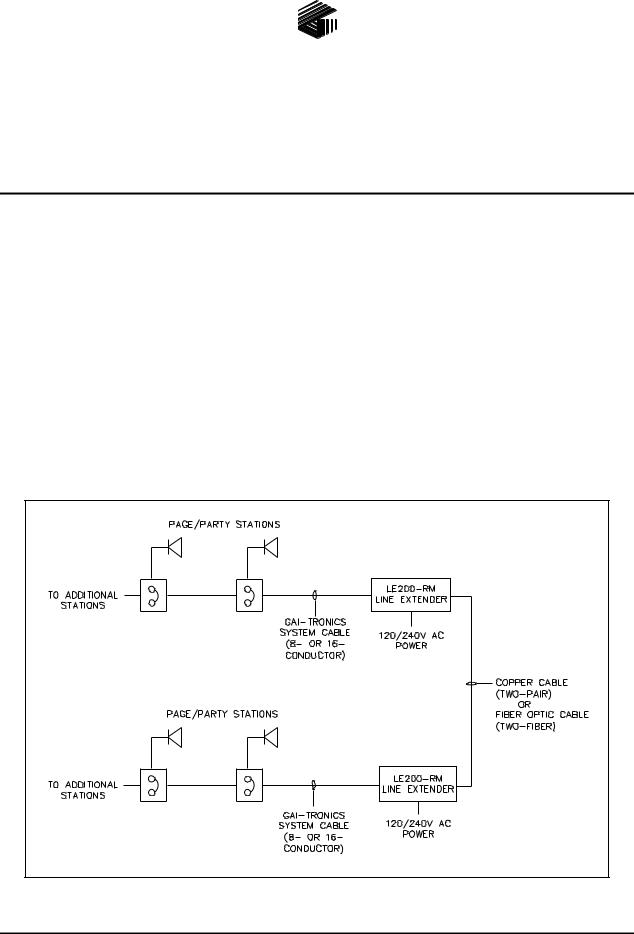
The Model LE200-RM Rack-Mount Page/Party® Line Extender is used in pairs to extend the operating distance of Page/Party®, SmartSeries or ICS Page/Party® systems. Two system cable segments are connected through the Line Extender using either a two-pair copper cable or fiber optic cable depending on the distance required. The local and remote cable segments are electrically isolated through the Line Extenders. Refer to Figure 1 for a typical block diagram.
Figure 1. Typical System Block Diagram
GAI-Tronics Corporation 400 E. Wyomissing Ave. Mohnton, PA 19540 USA
610-777-1374 800-492-1212 Fax: 610-796-5954
VISIT WWW.GAI-TRONICS.COM FOR PRODUCT LITERATURE AND MANUALS
MODEL LE200-RM RACK-MOUNT PAGE/PARTY® LINE EXTENDER |
Pub. 42004-392G |
PAGE 2 of 56 |
Line Extender and Sub-Component Details
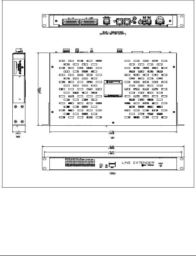
Refer to Figure 2 below for dimensional information and sub-component layout of the LE200-RM Line Extender.
Figure 2. Model LE200-RM Line Extender Outline
e:\standard ioms - current release\42004 instr. manuals\42004-392g.doc
09/14
MODEL LE200-RM RACK-MOUNT PAGE/PARTY® LINE EXTENDER |
Pub. 42004-392G |
PAGE 3 of 56 |
PCBAAccess
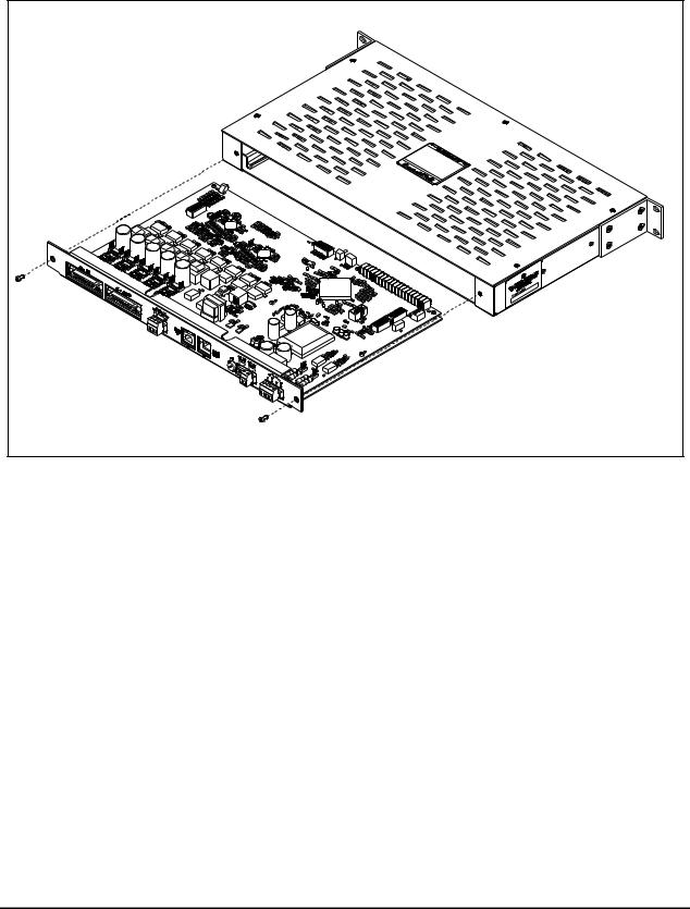
The Main PCBA can be easily accessed to set up switches and jumpers. Remove the two #6-32 screws from the rear of the unit. Slide the PCBA support plate and PCBA out of the unit. See Figure 3.
Figure 3. Access to the Model LE200-RM Line Extender’s Main PCBA
e:\standard ioms - current release\42004 instr. manuals\42004-392g.doc
09/14
MODEL LE200-RM RACK-MOUNT PAGE/PARTY® LINE EXTENDER |
Pub. 42004-392G |
PAGE 4 of 56 |
AudioTerminationConnectionModule–Optional Model 12118-011Kit
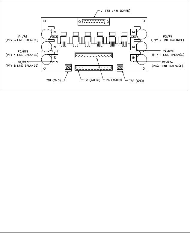
The GAI-Tronics Model 12118-011 Kit must be used if the LE200-RM is to be connected directly to a Page/Party® system. This kit consists of a ribbon cable for connection to the LE200-RM, an Audio Termination Connection Module for connection to the Page/Party® system and mounting hardware. The page line and party line 1–5 conductors of the Page/Party® system cable connect to the Audio Termination Connection Module. This module also can provide the 33-ohm line balance resistance needed for the audio lines. Audio line functions are described later in this manual.
Figure 4. Audio Termination Connection Module
e:\standard ioms - current release\42004 instr. manuals\42004-392g.doc
09/14
MODEL LE200-RM RACK-MOUNT PAGE/PARTY® LINE EXTENDER |
Pub. 42004-392G |
PAGE 5 of 56 |
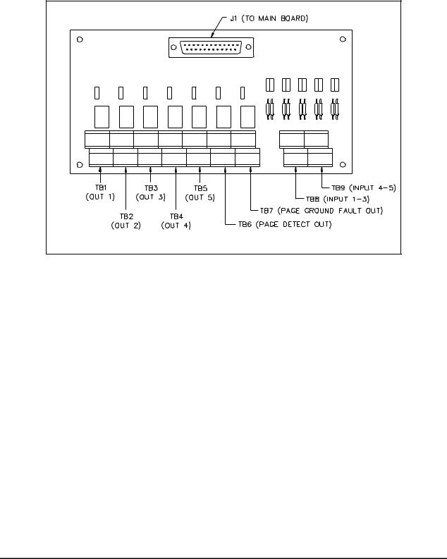
Input/Output (I//O)TerminationConnectionModule–Optional Model 12118-012Kit
If the LE200-RM is to be connected directly to I/O wiring then the GAI-Tronics Model 12118-011 Kit is required. This kit consists of a ribbon cable for connection to the LE200-RM, an I/O Termination Connection Module and mounting hardware. The I/O Termination Connection Module is for connecting the control wiring needed to send contact closures across the Line Extenders. I/O features and functions are described later in this manual.
Figure 5. Input/Output (I/O) Connection Module
e:\standard ioms - current release\42004 instr. manuals\42004-392g.doc
09/14

MODEL LE200-RM RACK-MOUNT PAGE/PARTY® LINE EXTENDER |
Pub. 42004-392G |
PAGE 6 of 56 |
MainPCBA
The Main PCBA contains all the central processing and line driver circuitry for the Line Extender. The board contains numerous connectors, switches and jumpers for setting the Line Extender operating parameters. Figure 6 below identifies the various components on the Main PCBA. Features and functions of each are described later in this manual.
Figure 6. 69443-xxx Main PCBA
e:\standard ioms - current release\42004 instr. manuals\42004-392g.doc
09/14

MODEL LE200-RM RACK-MOUNT PAGE/PARTY® LINE EXTENDER |
Pub. 42004-392G |
PAGE 7 of 56 |
Features and Functions
The Model LE200-RM Page/Party® Line Extenders provide the following features between Page/Party® system cables.
Page Line Audio Transmission
A pair of Model LE200-RMs provides page line audio transmission between two Page/Party® system cables. This transmission is half-duplex operation.
When the Line Extender detects a peak audio level equal or above a Peak Voltage Level Detection Threshold, it immediately switches audio “on” in that direction for the Transmission Direction Hold Time. Audio from the other direction is muted and ignored during that time. Audio is not switched “off” until it is continuously below the Peak Voltage Level Detection Threshold for the Transmission Direction Hold Time. The DIP switch SW2 positions 5–7, located on the Main PCBA, selects Peak Voltage Level Detection Threshold and Transmission Direction Hold Time. Refer to Figure 6 for the location of switch SW2 on the Main PCBA and Table 1 and Table 2 below for setting options.
Table 1. Transmission Direction Hold Time Settings on Main PCBA
SW2-5 |
SW2-6 |
Transmission Direction Hold Time |
|
|
|
|
|
|
Open* |
Open * |
1280 milliseconds |
|
|
|
Closed |
Open |
640 milliseconds |
|
|
|
Open |
Closed |
160 milliseconds |
|
|
|
Closed |
Closed |
40 milliseconds |
|
|
|
NOTES: 1. Changes to this parameter take effect without cycling power. 2. *Indicates default position.
Table 2. Peak Voltage Level Detection Threshold on Main PCBA
SW2-7 |
Peak Voltage Level Detection Threshold |
|
|
|
|
Open* |
−12 dB relative to nominal |
|
|
Closed |
−24 dB relative to nominal |
|
|
NOTES: 1. Changes to this parameter take effect without cycling power. 2. *Indicates default position.
e:\standard ioms - current release\42004 instr. manuals\42004-392g.doc
09/14

MODEL LE200-RM RACK-MOUNT PAGE/PARTY® LINE EXTENDER |
Pub. 42004-392G |
PAGE 8 of 56 |
Page Line Audio Monitoring Output
The Model LE200-RM provides a balanced 600-ohm audio output for monitoring audio on both the local and remote page lines. LE200-RM mixes the local and remote page line audio and routes it to the 600ohm audio output terminals. This audio can be sent to any external audio device (recorder, radio transmitter, amplifier, etc.) with an input impedance equal to or greater than 600 ohms. The audio output gain is adjustable using DIP switch SW3 positions 5–8 on the Main PCBA. Refer to Figure 6 for the location of switch SW3 on the Main PCBA and Table 3 below for setting options.
Table 3. Page Line Monitor Output Gain Setting on Main PCBA
|
|
|
|
Monitor Output |
SW3-5 |
SW3-6 |
SW3-7 |
SW3-8 |
Gain |
|
|
|
|
|
|
|
|
|
|
Open* |
Open* |
Open* |
Open* |
0 dB |
|
|
|
|
|
Closed |
Open |
Open |
Open |
−30 dB |
|
|
|
|
|
Open |
Closed |
Open |
Open |
−27 dB |
|
|
|
|
|
Closed |
Closed |
Open |
Open |
−24 dB |
|
|
|
|
|
Open |
Open |
Closed |
Open |
−21 dB |
|
|
|
|
|
Closed |
Open |
Closed |
Open |
−18 dB |
|
|
|
|
|
Open |
Closed |
Closed |
Open |
−15 dB |
|
|
|
|
|
Closed |
Closed |
Closed |
Open |
−12 dB |
|
|
|
|
|
Open |
Open |
Open |
Closed |
−9 dB |
|
|
|
|
|
Closed |
Open |
Open |
Closed |
−6 dB |
|
|
|
|
|
Open |
Closed |
Open |
Closed |
−3 dB |
|
|
|
|
|
Closed |
Closed |
Open |
Closed |
0 dB |
|
|
|
|
|
Open |
Open |
Closed |
Closed |
+3 dB |
|
|
|
|
|
Closed |
Open |
Closed |
Closed |
+6 dB |
|
|
|
|
|
Open |
Closed |
Closed |
Closed |
+9 dB |
|
|
|
|
|
Closed |
Closed |
Closed |
Closed |
+12 dB |
|
|
|
|
|
NOTES: 1. Changes to this parameter take effect without cycling power. 2. *Indicates default position.
e:\standard ioms - current release\42004 instr. manuals\42004-392g.doc
09/14
MODEL LE200-RM RACK-MOUNT PAGE/PARTY® LINE EXTENDER |
Pub. 42004-392G |
PAGE 9 of 56 |
Page Line Audio Detect Output Contact
The Model LE200-RM provides a contact closure output that activates whenever audio is detected on the page line. The contact can be set to close when audio is detected at the local page line, the remote page line, or both. Typically this contact is used in conjunction with the Page Line Audio Monitoring Output to provide a control contact to external devices or systems when page line audio is present. The contact remains active for 1 second after the audio is no longer detected. DIP switch SW5 positions 6 and 7 enables or disables the output contact. Refer to Figure 6 for the location of switch SW5 on the Main PCBA and Table 4 below for setting options.
Table 4. Page Line Audio Detect Contact Main PCBA
SW5-6 |
SW5-7 |
Audio Detect Contact Operation |
|
|
|
|
|
|
Closed |
Closed |
Disabled |
|
|
|
Open |
Closed |
Local page line audio activates the contact |
|
|
|
Closed |
Open |
Remote page line audio activates the contact |
|
|
|
Open* |
Open* |
Both local and remote page line audio activates the contact |
|
|
|
NOTES: 1. Changes to this parameter take effect without cycling power. 2. *Indicates default position.
Page Line FSK Data Transmission (SmartSeries Systems)
A pair of Model LE200-RM Line Extenders re-generates the FSK data transmission between two SmartSeries Page/Party® system cables. FSK data transmission occurs on the page line allowing SmartSeries Page/Party® stations to communicate with the system control cabinet. For proper operation, both Line Extenders must have this feature enabled by setting DIP switch SW5 position 1. Refer to Figure 6 for the location of switch SW5 on the Main PCBA and Table 5 below for setting options.
|
Table 5. Page Line FSK Transmission on Main PCBA |
|
|
SW5-1 |
Page Line FSK Transmission |
|
|
|
|
Open* |
FSK data is disabled. |
|
|
Closed |
FSK data is enabled. |
|
|
NOTES: 1. Changes to this parameter take effect without cycling power. 2. *Indicates default position.
NOTE: FSK operation and VLC operation (described below) cannot be enabled at the same time. FSK operation is only used with SmartSeries systems.
VLC operation is only used within NON-SmartSeries systems. If both VLC and FSK are enabled at the same time, neither feature will function correctly.
e:\standard ioms - current release\42004 instr. manuals\42004-392g.doc
09/14

MODEL LE200-RM RACK-MOUNT PAGE/PARTY® LINE EXTENDER |
Pub. 42004-392G |
PAGE 10 of 56 |
Page Line 50 kHz VLC Transmission
A pair of Model LE200-RM Line Extenders re-generates the 50 kHz VLC control signal between two Page/Party® system cables. 50 kHz VLC signaling occurs on the page line and is typically used to alter the speaker volume of Page/Party® stations equipped VLC receivers. VLC signals may also be used for other on/off control functions on some Page/Party® systems. For proper operation, both Line Extenders must have this feature enabled by setting DIP switch SW5 position 2. Refer to Refer to Figure 6 for the location of switch SW5 on the Main PCBA and Table 6 below for setting options.
Table 6. Page Line 50 kHz VLC Transmission Setting on Main PCBA
SW5-2 Page Line 50 kHz VLC Transmission
Open* |
50 kHz VLC is disabled. |
|
|
Closed |
50 kHz VLC is enabled. |
|
|
NOTES: 1. Changes to this parameter take effect without cycling power. 2. *Indicates default position.
NOTE: FSK operation and VLC operation (described above) cannot be enabled at the same time. FSK operation is only used with SmartSeries systems.
VLC operation is only used within NON-SmartSeries systems. If both VLC and FSK are enabled at the same time, neither feature will function correctly.
Page Line Ground Fault Detection
The Model LE200-RM Line Extenders provide page line ground fault detection on the local Page/Party® system cable. If multiple LE200-RMs are connected to the same Page/Party® system cable segment, only one page line ground fault detector may be enabled. A shorting clip setting at header P5 on the Main PCBA enables the page line ground fault detection. Refer to Figure 6 for the location of header P5 on the Main PCBA and Table 7 below for setting options:
Table 7. Page Line Ground Fault Detection Setting on Main PCBA
P5 Shorting Clip |
Page Line Ground Fault Detection |
|
|
|
|
Pins 1–2* |
Page line ground fault detection is disabled. |
|
|
Pins 2–3 |
Page line ground fault detection is enabled. |
|
|
Removed |
Page line ground fault detection is disabled. |
|
|
NOTES:
1.If connecting an LE200-RM to the same system cable segment as an ADVANCE Page/Party® Interface (PPI) card, disable the LE200-RM page line ground fault detector. The PPI card contains the ground fault detector. If both ground fault circuits are enabled simultaneously, intermittent SmartSeries FSK data errors will occur between the PPI card and SmartSeries stations.
2.Changes to this parameter take effect without cycling power.
3.*Indicates default position.
e:\standard ioms - current release\42004 instr. manuals\42004-392g.doc
09/14

MODEL LE200-RM RACK-MOUNT PAGE/PARTY® LINE EXTENDER |
Pub. 42004-392G |
PAGE 11 of 56 |
Page Line Ground Fault Re-generation
When a ground fault is detected at a remote LE200-RM Line Extender, the ground fault can be duplicated on the local Page/Party® system cable. DIP switch SW5 position 3 enables regeneration of the ground fault. Refer to Figure 6 for the location of switch SW5 on the Main PCBA and Table 8 below for setting options.
|
Table 8. Page Line Ground Fault Regeneration Setting on Main PCBA |
|
|
SW5-3 |
Page Line Ground Fault Regeneration |
|
|
|
|
Open* |
Disabled - Page line ground faults detected on the remote system cable are NOT |
|
regenerated on the local system cable. |
|
|
Closed |
Enabled - Page line ground faults detected on the remote system cable are regenerated on |
|
the local system cable. |
|
|
NOTES:
1.The ground fault regeneration feature is used in SmartSeries systems to allow a ground fault on the remote cable segment to be detected by the system control cabinet. Disable this feature if the Line Extender is not installed in this type system.
2.Changes to this parameter take effect without cycling power.
3.*Indicates default position.
Page Line Ground Fault Output Contact
The Model LE200-RM provides a relay contact that activates whenever a ground fault is detected on the local page line, remote page line or both the page lines. The ground fault detection feature (described above) must be enabled. The contact output can be used to activate an external device or system which annunciates the fault condition. The DIP switch SW5 positions 4 and 5 configure which page line ground faults activate this contact. Refer to Figure 6 for the location of switch SW5 on the Main PCBA and Table 9 below for setting options.
Table 9. Page Line Ground Fault Contact Setting on Main PCBA
SW5-4 |
SW5-5 |
Page Line Ground Fault Contact |
|
|
|
|
|
|
Closed |
Closed |
Disabled |
|
|
|
Closed |
Open |
Remote page line ground fault activates the contact. |
|
|
|
Open |
Closed |
Local page line ground fault activates the contact. |
|
|
|
Open* |
Open* |
Both Local and Remote page line ground faults activate the contact. |
|
|
|
NOTES: 1. Changes to this parameter take effect without cycling power. 2. *Indicates default position.
e:\standard ioms - current release\42004 instr. manuals\42004-392g.doc
09/14

MODEL LE200-RM RACK-MOUNT PAGE/PARTY® LINE EXTENDER |
Pub. 42004-392G |
PAGE 12 of 56 |
Party Line Audio Transmission
A pair of Model LE200-RM Line Extenders provides full duplex party line audio between two Page/Party® system cables, for party lines 1–5. During on-hook conditions of the party lines (meaning no handset stations are in use), the LE200-RM will mute the local party line analog circuits. If it is necessary to have party line audio enabled even when no stations are off-hook, DIP switch SW6-3 may be closed to disable this muting feature. This switch affects the on-hook muting function of all five party lines simultaneously. Refer to Figure 6 for the location of switch SW6 on the Main PCBA and Table 10 below for setting options.
|
Table 10. Party Line On-Hook Muting Setting on Main PCBA |
|
|
SW6-3 |
Party Line On-Hook Muting |
|
|
|
|
Open* |
Enabled – local party lines are muted when no handset stations are in-use. |
|
|
Closed |
Disabled – party line audio is never muted. |
|
|
NOTES: 1. Changes to this parameter take effect without cycling power. 2. *Indicates default position.
Party Line Off-Hook Regeneration
When an off-hook handset station is detected, the LE200-RM can transmit the off-hook condition to remote Line Extenders so that it is duplicated on the remote Page/Party® system cable. Typically this feature is used in systems that contain a telephone interface device so that the caller is transferred to the party line when a handset station answers the call. DIP switch SW6 position 2 is used to enable this feature. This switch affects the off-hook regeneration function of all five party lines. Refer to Figure 6 for the location SW6 on the Main PCBA and the Table 11 below for setting options.
|
Table 11. Off-Hook Regeneration on Main PCBA |
|
|
SW6-2 |
Off-Hook Regeneration Setting |
|
|
|
|
Open* |
Enabled – an off hook condition on the local party line is regenerated at the |
|
remote Line Extender. |
|
|
Closed |
Disabled |
|
|
NOTES: 1. Changes to this parameter take effect without cycling power. 2. *Indicates default position.
e:\standard ioms - current release\42004 instr. manuals\42004-392g.doc
09/14

MODEL LE200-RM RACK-MOUNT PAGE/PARTY® LINE EXTENDER |
Pub. 42004-392G |
PAGE 13 of 56 |
Party Line Off-Hook Detection
The Model LE200-RM Line Extenders provide off-hook detection on the local Page/Party® system cable for party lines 1 through 5. An off-hook condition means a handset station is in use. If multiple Line Extenders are connected to the same Page/Party® system cable segment, only one off-hook detector can be enabled. If connecting an LE200-RM to the same system cable segment as an ADVANCE Page/Party Interface (PPI) card, disable the LE200-RM off-hook detection for party lines 1 and 2. The PPI card contains off-hook detection for party lines 1 and 2.
Several shorting clips (P6–P15) are used to enable the off-hook detection feature on party line 1 through 5. Two shorting clips are associated with each party line and must be set to the same position for proper operation. The party lines 1–5 are configured independently. Refer to Figure 6 for the location of P6–P15 on the Main PCBA and Table 12 below for setting options.
Table 12. Party Line Off-Hook Detection Setting on Main PCBA
Party Line |
Headers |
Shorting Clip |
Off-Hook Detection |
|
|
|
|
|
|
|
|
|
|
|
|
|
|
Pins 1–2* |
Disabled |
|
|
|
|
|
Party Line 1 |
P15, |
P14 |
Pins 2–3 |
Enabled |
|
|
|
|
|
|
|
|
Removed |
Disabled |
|
|
|
|
|
|
|
|
Pins 1–2* |
Disabled |
|
|
|
|
|
Party Line 2 |
P13, |
P12 |
Pins 2–3 |
Enabled |
|
|
|
|
|
|
|
|
Removed |
Disabled |
|
|
|
|
|
|
|
|
Pins 1–2* |
Disabled |
|
|
|
|
|
Party Line 3 |
P11, |
P10 |
Pins 2–3 |
Enabled |
|
|
|
|
|
|
|
|
Removed |
Disabled |
|
|
|
|
|
|
|
|
Pins 1–2* |
Disabled |
|
|
|
|
|
Party Line 4 |
P9, |
P8 |
Pins 2–3 |
Enabled |
|
|
|
|
|
|
|
|
Removed |
Disabled |
|
|
|
|
|
|
|
|
Pins 1–2* |
Disabled |
|
|
|
|
|
Party Line 5 |
P7, |
P6 |
Pins 2–3 |
Enabled |
|
|
|
|
|
|
|
|
Removed |
Disabled |
|
|
|
|
|
NOTES:
1.Changes to this parameter take effect without cycling power.
2.*Indicates default position.
e:\standard ioms - current release\42004 instr. manuals\42004-392g.doc
09/14

MODEL LE200-RM RACK-MOUNT PAGE/PARTY® LINE EXTENDER |
Pub. 42004-392G |
PAGE 14 of 56 |
Audio Line Connection Relays
The Model LE200-RM has relays that disconnect the page, party lines 1–5 and the page monitoring output connections from the Main PCBA. The disconnect feature is used for special applications such as connection of a single party line system or other scenarios in which a particular audio line is not physically connected to the Line Extender. DIP switch SW4 is used to control the audio line disconnect feature. Refer to Figure 6 for the location of SW4 on the Main PCBA and Table 13 below for setting options.
Table 13. Audio Line Connection Relay Settings on Main PCBA
Audio Line |
Switch SW4 |
Setting |
Field Wiring |
|
|
|
|
|
|
|
|
|
|
|
Party line 5 |
SW4-1 |
Open |
Disconnected |
|
|
|
|||
Closed* |
Connected |
|||
|
|
|||
|
|
|
|
|
Party line 4 |
SW4-2 |
Open |
Disconnected |
|
|
|
|||
Closed* |
Connected |
|||
|
|
|||
|
|
|
|
|
Party line 3 |
SW4-3 |
Open |
Disconnected |
|
|
|
|||
Closed* |
Connected |
|||
|
|
|||
|
|
|
|
|
Party line 2 |
SW4-4 |
Open |
Disconnected |
|
|
|
|||
Closed* |
Connected |
|||
|
|
|||
|
|
|
|
|
Party line 1 |
SW4-5 |
Open |
Disconnected |
|
|
|
|||
Closed* |
Connected |
|||
|
|
|||
|
|
|
|
|
Page line |
SW4-6 |
Open |
Disconnected |
|
|
|
|||
Closed* |
Connected |
|||
|
|
|||
|
|
|
|
|
Page monitor |
SW4-7 |
Open |
Disconnected |
|
|
|
|||
Closed* |
Connected |
|||
|
|
|||
|
|
|
|
|
N/A |
SW4-8 |
Open |
Not used |
|
|
||||
Closed* |
||||
|
|
|
||
|
|
|
|
NOTES: 1. Changes to this parameter take effect without cycling power. 2. *Indicates default position.
e:\standard ioms - current release\42004 instr. manuals\42004-392g.doc
09/14

MODEL LE200-RM RACK-MOUNT PAGE/PARTY® LINE EXTENDER |
Pub. 42004-392G |
PAGE 15 of 56 |
Audio Line Muting
In some system configurations, the Page/Party® system cable is not connected to the Line Extender. In this case, all audio lines (page and party lines 1–5) should be muted since they are not physically connected. DIP switch SW6 position 4 on the Main PCBA enables this feature. If this feature is enabled, it is unnecessary to disconnect the audio lines using the audio line relays (mentioned above). Refer to Figure 6 for the location of SW6 on the Main PCBA and Table 14 below for setting options.
|
Table 14. Audio Line Mute Setting on Main PCBA |
|
|
SW6-4 |
Mute Analog Lines Setting |
|
|
|
|
Open* |
Disabled - Party lines 1–5 and page line are operational. |
|
|
Closed |
Enabled - Party lines 1–5 and page line are muted. |
|
|
NOTES: 1. Changes to this parameter take effect without cycling power. 2. *Indicates default position.
e:\standard ioms - current release\42004 instr. manuals\42004-392g.doc
09/14

MODEL LE200-RM RACK-MOUNT PAGE/PARTY® LINE EXTENDER |
Pub. 42004-392G |
PAGE 16 of 56 |
Page/Party®Line Balance
For proper system operation, the page line and party lines 1–5 must be terminated with a resistance of approximately 33 ohms. The Model LE200-RM provides potentiometers to set the line balance resistance on the page line and five party lines. The line balance resistors are located on the Audio Termination Connection Module (part of Model 12118-011 Kit) next to the page and party line terminal blocks. The line balance resistors are adjustable or can be disabled using shorting clips P1–P7.
If connecting an LE200-RM to the same system cable segment as an ADVANCE Page/Party Interface (PPI) card, disable the line balance for party lines 1, 2 and the page line. The PPI card provides the line balance resistors for these audio lines. Refer to Figure 4 for the location of the jumpers and potentiometers on the Audio Termination Connection Module and the Table 15 for setting details.
Table 15. Page/Party® Line Balance Settings on Audio Termination Connection Module
|
|
|
|
|
Adjustment |
Audio Line |
Header |
Shorting Clip |
Line Balance |
|
Potentiometer |
|
|
|
|
|
|
|
|
|
|
|
|
|
|
Pins 1–2* |
Disabled |
|
|
|
|
|
|
|
|
Party line 5 |
P6 |
Pins 2–3 |
Enabled |
|
R23 |
|
|
|
|
|
|
|
|
Removed |
Disabled |
|
|
|
|
|
|
|
|
|
|
Pins 1–2* |
Disabled |
|
|
|
|
|
|
|
|
Party line 4 |
P3 |
Pins 2–3 |
Enabled |
|
R19 |
|
|
|
|
|
|
|
|
Removed |
Disabled |
|
|
|
|
|
|
|
|
|
|
Pins 1–2* |
Disabled |
|
|
|
|
|
|
|
|
Party line 3 |
P1 |
Pins 2–3 |
Enabled |
|
R3 |
|
|
|
|
|
|
|
|
Removed |
Disabled |
|
|
|
|
|
|
|
|
|
|
Pins 1–2* |
Disabled |
|
|
|
|
|
|
|
|
Party line 2 |
P2 |
Pins 2–3 |
Enabled |
|
R4 |
|
|
|
|
|
|
|
|
Removed |
Disabled |
|
|
|
|
|
|
|
|
|
|
Pins 1–2* |
Disabled |
|
|
|
|
|
|
|
|
Party line 1 |
P4 |
Pins 2–3 |
Enabled |
|
R20 |
|
|
|
|
|
|
|
|
Removed |
Disabled |
|
|
|
|
|
|
|
|
|
|
Pins 1–2* |
Disabled |
|
|
|
|
|
|
|
|
Page line |
P7 |
Pins 2–3 |
Enabled |
|
R24 |
|
|
|
|
|
|
|
|
Removed |
Disabled |
|
|
|
|
|
|
|
|
NOTES: *Indicates default position.
e:\standard ioms - current release\42004 instr. manuals\42004-392g.doc
09/14
 Loading...