


 Loading...
Pub. 42004-307G
G A I - T R O N I C S ® C O R P O R A T I O N
A H U B B E L L C O M P A N Y
Model GC-AC1, GC-DC1, and GC-AC2
EZ Page Industrial Intercoms
Confidentiality Notice
This manual is provided solely as an operational, installation, and maintenance guide and contains sensitive business and technical information that is confidential and proprietary to GAI-Tronics. GAI-Tronics retains all intellectual property and other rights in or to the information contained herein, and such information may only be used in connection with the operation of your GAI-Tronics product or system. This manual may not be disclosed in any form, in whole or in part, directly or indirectly, to any third party.
General Information
Product Overview
GAI-Tronics’ EZ Page Intercoms are designed for two-way communication in non-hazardous, industrial applications. Each model is field configurable for one of two types of systems: either Listen/Talk or Master/Slave. All units are factory-configured for the Listen/Talk system.
Listen/Talk System
In a Listen/Talk system, the press-to-talk switch must be held down as long as the operator talks. Releasing the switch deactivates the microphone and returns the unit to the listen mode.
Master/Slave System
In a Master/Slave system the Master unit controls the talk/listen operation of the Slave unit. The Slave unit is normally in the talk mode, providing hands-free communication to the operator. The Master/Slave system is ideal for typical gate station applications. An internal switch is used to designate a unit as a master or as a slave.
Balanced andUnbalanced Systems
Figure 1. Intercom Outline Diagram (shown with optional mounting bracket installed)
The EZ Page system is a balanced system; however, it can be adapted for use in an unbalanced system. If interfacing this equipment with other similar products on the market, determine if your system is balanced or unbalanced.
GAI-Tronics Corporation 400 E. Wyomissing Ave. Mohnton, PA 19540 USA
610-777-1374 800-492-1212 Fax: 610-796-5954
VISIT WWW.GAI-TRONICS.COM FOR PRODUCT LITERATURE AND MANUALS

|
Pub. 42004-307G |
EZ PAGE INDUSTRIAL INTERCOMS |
Page 2 of 16 |
The setting of an internal jumper and the external wiring interconnection scheme are different in a balanced system and an unbalanced system. Refer to the appropriate installation instructions provided in this manual.
System Requirements
Each unit requires local power within approximately 9.5 feet of unit for interconnection of unit’s audio/control cable to system cable.
NOTE: If applicable local electrical codes permit, the use of a combined UL-approved junction box for termination of the unit’s local power connection
and audio/control to system cable could be |
|
Input |
Interconnection |
|
helpful. |
|
|||
Models |
Voltage |
(Customer-supplied) |
||
|
||||
CableDistance Limitations |
|
|
|
|
|
|
|
||
GC-AC1 |
120 V ac |
NEMA 5-15R style receptacle |
||
NOTE: Calculations are based on the use of No. |
|
|
|
|
GC-DC1 |
12-16 V dc |
Small junction box for Class 2 |
||
18 AWG twisted pair wire. |
|
|
wiring |
|
Audio Pair |
GC-AC2 |
230 V ac |
Small UL-approved junction |
|
|
|
box or plug rated for this |
||
|
|
|
||
Maximum distance from the line balance is |
|
|
voltage |
|
approximately 1 mile (1.6 km). Maximum |
|
|
|
|
distance between the two end units is approximately 2 miles (3.2 km). |
|
|||
External Control Pair
Maximum distance between the two end units is approximately 2 miles (3.2 km).
System Cable
Recommend use of twisted, two pair cable (No. 18 AWG) between stations for maximum system hum/noise immunity. Extreme hum/noise areas may require shielded twisted, two pair cable.
Installation
Since a good installation is important in obtaining the best possible performance of the communications system, determine the operating mode of each unit and carefully plan the overall installation before actual work is started. Read the entire procedure and the many suggestions offered to help you plan your installation.
DANGER |
Do not install in a hazardous area. Use in safe, non-classified, non-hazardous |
|
areas only. |
||
|
||
WARNING |
Please adhere to all the following safety and operating instructions on the |
unit and in the installation manual:
Ensure that the installation is in accordance with all local applicable electrical codes.
Disconnect power to the unit before opening or servicing to avoid possible damage to equipment or personal injury.
Avoid running system cable near high voltage/high electromagnetic sources.
Avoid servicing the unit during electrical storms.
Do not touch non-insulated wires.
f:\standard ioms - current release\42004 instr. manuals\42004-307g.doc 03/15
|
Pub. 42004-307G |
EZ PAGE INDUSTRIAL INTERCOMS |
Page 3 of 16 |
Internal Settings
The following procedure describes how to change the internal settings. If the intercom will be used as a Listen/Talk unit or as a Master unit in a balanced line system, then no changes to the internal PCBA’s jumper or switch settings are required.
 WARNING
Disconnect power to unit before opening to avoid possible damage to equipment or personal injury.
1.Disconnect power to the unit.
2.Loosen and remove the six screws securing the front cover.
3.Lift out the front panel assembly and tilt to the left. Use caution to ensure that no unnecessary strain is placed on the attached wiring harnesses.
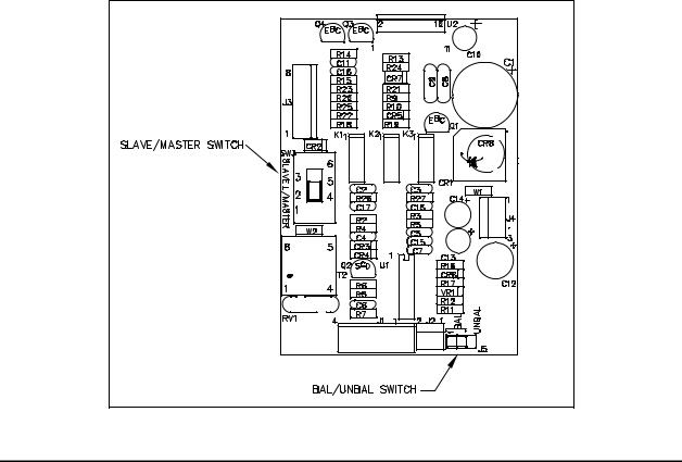
4.If configuring the unit as a slave, slide the PCBA’s mode switch (SW3) to the SLAVE position. See Figure 2.
5.If operating in an unbalanced cable system, reposition the PCBA’s jumper P5/J5 from the BAL position to the UNBAL position. See Figure 2.
6.Reinsert the front panel assembly into the rear housing. Ensure that no wires are between the front panel’s gasket and the housing’s sealing surface that could be pinched.
7.Reinsert the six screws into the front cover and tighten securely.
8.Reapply the unit power and check for proper operation.
Figure 2. PCBA Outline Detail
f:\standard ioms - current release\42004 instr. manuals\42004-307g.doc 03/15

|
Pub. 42004-307G |
EZ PAGE INDUSTRIAL INTERCOMS |
Page 4 of 16 |
Power Connection
 WARNING
Installation techniques must comply with all applicable electrical safety hazards/electrical codes.
Remove local power before opening the unit or before performing any service.
Input |
|
|
|
|
|
|
|
|
|
Voltage |
Model |
Conductor 1 |
Conductor 2 |
Conductor 3 |
Conductor 4 |
||||
|
|
|
|
|
|
|
|
|
|
|
|
|
|
|
|
|
|
|
|
120 V ac via |
GC-AC1 |
Hot |
Black |
Neutral |
White |
Safety |
Green |
N/A |
-- |
supplied 9.5-foot |
|
|
|
|
|
ground |
|
|
|
cord w/NEMA |
|
|
|
|
|
|
|
|
|
5-15P plug |
|
|
|
|
|
|
|
|
|
|
|
|
|
|
|
|
|
|
|
12–16 V dc |
GC-DC1 |
(+) |
Red |
(−) |
Black |
Safety |
Green |
Not |
White |
(See note) |
|
|
|
|
|
ground |
|
used |
|
|
|
|
|
|
|
|
|
(cut off) |
|
|
|
|
|
|
|
|
|
|
|
230 V ac |
GC-AC2 |
Hot |
Red |
Neutral |
White |
Safety |
Green |
Not |
Black |
(See note) |
|
|
|
(non- |
|
ground |
|
used |
|
|
|
|
|
US) |
|
|
|
(cut off) |
|
|
|
|
|
|
|
|
|
|
|
NOTES:
1.For Model GC-DC1 (12–16 V dc), the integral power cable is designed for connection to Class 2 circuits. For Model GC-AC2 (230 V ac) termination of the integral primary power cable must be made using a UL-approved junction box. If a customer-supplied interconnect plug is desired for interconnect, the plug must be UL-approved and rated for such purposes.
2.The audio/control wiring for all models is designed for connection to Class 2 circuits.
Mounting Instructions
The wall’s mounting surface composition and hardware to be used (customer-supplied) must be suitable to withstand the unit’s weight to prevent damage and/or personal injury.
If the unit is mounted to building structure, GTC Part No. 12704-001 Mounting Bracket Kit should be used. Refer to Pub. 42003-134 that accompanies the kit for more information.
There are two 0.406-inch (10.4 mm) diameter holes located in the mounting flanges spaced 5.875 inches (149.3 mm) apart. See Figure 1. The suggested mounting height for all station enclosures is 54 inches (137 cm) from the floor to the centerline of the enclosure.
Connection Instructions
System LineBalance
Each system requires termination of the audio pair wires with the 1 k /1-watt resistor assembly included with each unit. The line balance resistor assembly is made for easy installation into the customersupplied junction box. Only one line balance resistor assembly is needed per system.
For cable runs that are approximately 0.75 mile (1.2 km) or longer, it is recommended that the resistor assembly be installed in a junction box that is close to the center of the system.
f:\standard ioms - current release\42004 instr. manuals\42004-307g.doc 03/15
|
Pub. 42004-307G |
EZ PAGE INDUSTRIAL INTERCOMS |
Page 5 of 16 |
SystemInterconnect
Refer to the interconnection diagram that is appropriate to the type of system you are installing.
Reminder about balanced and unbalanced systems: If interconnecting to an unbalanced system, be sure to move the Intercom’s internal jumper (P5/J5) to the UNBAL position. For example, GAI-Tronics RigCom products use an unbalanced system; therefore, the Intercom’s internal jumper (P5/J5) must be moved to the UNBAL position.
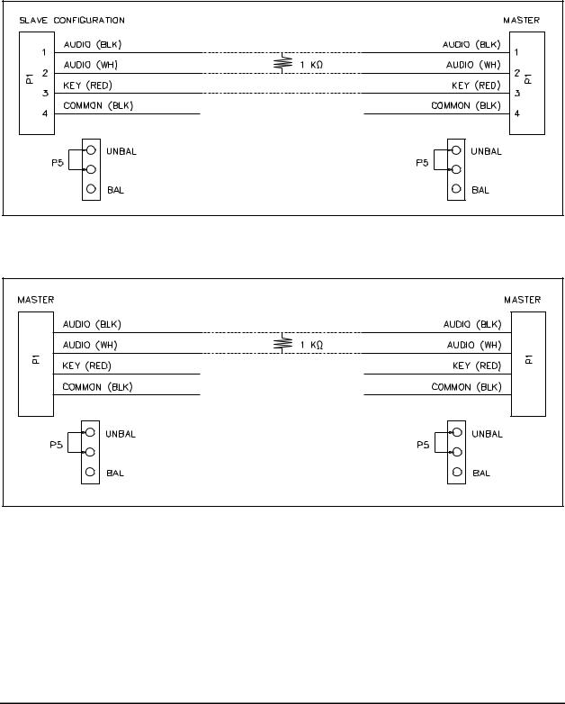
Figure 3. Master/Slave Unbalanced Configuration
Figure 4. Unbalanced Common Line Configuration
f:\standard ioms - current release\42004 instr. manuals\42004-307g.doc 03/15

|
Pub. 42004-307G |
EZ PAGE INDUSTRIAL INTERCOMS |
Page 6 of 16 |
Figure 5. Master/Slave Balanced Configuration
Figure 6. Balanced Common Line Configuration
f:\standard ioms - current release\42004 instr. manuals\42004-307g.doc 03/15
Loading...